TESTO 6383 Instruction Manual
Differential pressure transmitter, probes
Hide thumbs
Also See for 6383:
- Instruction manual (140 pages) ,
- Instruction manual (88 pages) ,
- Instruction manual (76 pages)
Table of Contents
Advertisement
Quick Links
Download this manual
See also:
Instruction Manual
Advertisement
Table of Contents

Related Manuals for TESTO 6383


Summary of Contents for TESTO 6383
- Page 1 6383 · differential pressure transmitter testo 6610 · Probes P2A software · Parameterizing, adjusting and analyzing software Instruction manual Volume 1...
-
Page 3: Safety And The Environment
Pos: 8 /TD/Sicherheit und Umwelt/Sicherheit gewährleisten/MUF 63xx/Fachpersonal @ 3\mod_1234794940409_79.doc @ 26337 @ Any additional work must only be carried out by authorized personnel. Otherwise testo will not accept any responsibility for the proper functioning of the instrument after repair and for the validity... -
Page 4: About This Document
> At the end of its useful life, send the product to the separate collection for electric and electronic devices (observe local regulations) or return the product to Testo for disposal. Pos: 11 /TD/Überschriften/MUF/Zu diesem Dokument @ 3\mod_1234793991331_79.doc @ 26242 @ 1 About this document Pos: 12 /TD/Sicherheit und Umwelt/Zu diesem Dokument/Verwendung (Standard) @ 0\mod_1173775068554_79.doc @ 337 @ 5... -
Page 5: Table Of Contents
4.3.2.8. Analog output adjustment ..............32 4.3.2.9. n-point adjustment (pressure) ............33 4.3.2.10. High-humidity adjustment for testo 6614 ........34 4.3.2.11. Self adjustment of testo 6615 trace humidity probe....35 4.4. Operation..................36 4.4.1. Relationship between user menu and mini-DIN socket is active ....36 4.4.2. - Page 6 3 Contents 4.4.5.2. Editing Main Menu Channel 2 (if this option is available) ....41 4.4.5.3. Editing Main Menu Channel 3 (if this option is available) ....42 4.4.5.4. Editing Main Menu Alarm..............42 4.4.5.5. Editing Main Menu Settings .............. 44 4.4.5.6.
-
Page 7: Transmitter
The testo 6383 transmitter is suitable for the following applications, amongst others: • Clean rooms • Complex room climate applications Pos: 22 /TD/Leistungsbeschreibung/Lieferumfang/MUF 63xx/MUF 6383, 6385 @ 4\mod_1254749193798_79.doc @ 51251 @ 3 4.1.2. Scope of delivery The scope of delivery of the testo 6383 transmitter includes the following: •... -
Page 8: Technical Data
4 Transmitter Pos: 24 /TD/Leistungsbeschreibung/Technische Daten/MUF 63xx/MUF 6383 @ 4\mod_1252499023732_79.doc @ 48869 @ 355555555555555555555555 4.1.4. Technical data Parameters • Differential pressure • Temperature • Humidity Differential pressure accuracy The specifications are only valid if the positive pressure is applied at the positive pressure connection. - Page 9 Upon delivery and following a factory reset the readings are shown in the display in the unit that was ordered via the KMAT option Fxx, see Ordering options for testo 6383 transmitter (0555 6383), page 133. Humidity and temperature resolution •...
-
Page 10: Analog Output
4 Transmitter Maximal load • 4-wire: 10 kΩ (voltage output) Analog output • 0 to 1 V ± 1.5 mV (4-wire) or • 0 to 5 V ± 7.5 mV (4-wire) or • 0 to 10 V ± 15 mV (4-wire) or •... - Page 11 Version with preparation for external humidity probe: approx. 1.26 kg Protection class, frontal • IP 65 only if the transmitter is wired and/or sealing plugs are inserted Directives, standards and tests • EC Directive: 2004/108/EC Warranty • Duration: 2 years • Warranty conditions: see website www.testo.com/warranty...
-
Page 12: Dimensions
4 Transmitter Pos: 25 /TD/Leistungsbeschreibung/Technische Daten/MUF 63xx/MUF Panel lang Abmessungen @ 4\mod_1255092618418_79.doc @ 51743 @ 3 4.1.5. Dimensions... -
Page 13: Product Description
4 Transmitter Pos: 26 /TD/Überschriften/MUF/1.2/2.2 Produktbeschreibung @ 3\mod_1234258723551_79.doc @ 24008 @ 2 4.2. Product description Pos: 27 /TD/Produktbeschreibung/Übersicht/MUF 63xx/Auf einen Blick 6383 @ 4\mod_1252499456455_79.doc @ 48901 @ 3 4.2.1. At a glance 1 Sealing plugs on the positive pressure test connection... -
Page 14: Usable Probes
15 Probe socket Pos: 28 /TD/Produktbeschreibung/Übersicht/MUF 63xx/Verwendbare Fühler Panel @ 4\mod_1252670326817_79.doc @ 50119 @ 3 4.2.2. Usable probes The testo 6383 transmitter can be used with the following probes: Probes Article no. Characteristic Wall probe version; accuracy to ±1 % RH;... -
Page 15: Display And Keypad
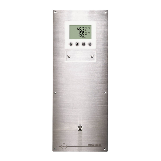
Pos: 29 /TD/Produktbeschreibung/Übersicht/MUF 63xx/Display und Tastatur @ 3\mod_1234773965059_79.doc @ 25650 @ 3 4.2.3. Display and keypad The display option allows operation of the testo 6383 transmitter via the display and four keys. The LCD display consists of two 7-segment lines for displaying readings and units and of an information line (for status messages, for example). -
Page 16: Analog Outputs
1 or optionally 3 voltage outputs of 0 to 1 V/0 to 5 V/0 to 10 V (4-wire). The transmitter can be ordered with three analog outputs as an option. The optional three channels are galvanically isolated. Pos: 34 /TD/Produktbeschreibung/Übersicht/MUF 63xx/Messgrößen 6383/6385 @ 3\mod_1234774693900_79.doc @ 25745 @ 3 4.2.7. Parameters The following parameters are displayed •... -
Page 17: Scaling
4 Transmitter Pos: 35 /TD/Produktbeschreibung/Übersicht/MUF 63xx/Skalierung @ 3\mod_1234775406989_79.doc @ 25783 @ 3 4.2.8. Scaling There are three types of min./max. values: 1 The measuring range: The maximum sensor performance is in this range. Values outside of the measuring range are displayed via messages, for example. - Page 18 4 Transmitter Measuring Maximum scaling range/standard scaling 0 to 50 Pa -5 to 15 Pa -500 to 500 Pa -1000 to 1000 -10 to 10 hPa -20 to 20 hPa Pos: 37 /TD/Produktbeschreibung/Übersicht/MUF 63xx/Tabelle Skalierung Fühler Panel @ 5\mod_1257519388289_79.doc @ 52767 @ Parameter Unit Probes...
-
Page 19: Alarm Handling
The testo 6383 monitors limit values with the help of relays. If a reading is outside the limit values, a relay to be specified by the user is switched. -
Page 20: Commissioning
4 Transmitter Pos: 39 /TD/Überschriften/MUF/1.3/2.3 Inbetriebnahme @ 3\mod_1234258805768_79.doc @ 24027 @ 2 4.3. Commissioning Pos: 40 /TD/Erste Schritte/MUF 63xx/Wandmontage Panel @ 4\mod_1251818568448_79.doc @ 48051 @ 3 4.3.1. Mounting preparations... -
Page 21: Connecting The Instrument
4 Transmitter 1. Create a wall opening (approx. 120 mm x 220 mm) at the mounting location. 2. Hold 6383 in assembly position and mark the drill holes. 3. Drill holes suitable for the screws to be used. 4. Connect 6383. -
Page 22: Overview Of Terminals
4 Insulating trough for relay below the relay cover board (option), below the relay cover The following description of the terminals refer to this overview and its numbering. Pos: 43 /TD/Erste Schritte/MUF 63xx/Spannungsversorgung/Analogausgänge anschließen 6383/6385 @ 4\mod_1254489681844_79.doc @ 51173 @ 45... -
Page 23: Connecting Voltage Supply And Analog Outputs
4 Transmitter 4.3.2.2. Connecting voltage supply and analog outputs Terminal strip for voltage supply and analog outputs, item (1) of overview of terminals Wiring diagram for 4-wire system (0 to 20 mA/4 to 20 mA/0 to 1 V/0 to 5 V/0 to 10 V) 1 1 or 3 channels, 0 to 20 mA/4 to 20 mA max. -
Page 24: Connecting The Relay Outputs
4 Transmitter Pos: 44 /TD/Erste Schritte/MUF 63xx/Relaisausgänge anschließen Panel @ 4\mod_1251814425917_79.doc @ 47891 @ 4555 4.3.2.3. Connecting the relay outputs Only have the transmitter wired and connected by authorized personnel with the voltage disconnected. Relay terminal strip, item (2) of overview of terminals There is the option of twelve terminals for a total of four relays. - Page 25 4 Transmitter • It is recommended that you always tie 2 adjacent cores to one another using a cable tie (3). • The insulation of the cable must be fed at least 5 mm (4) into the relay tray up to the elevated part. Use of relay as NC contact (NC = normally closed) 1 Alarm/status light (example of installation)
- Page 26 4 Transmitter Use of relay as NO contact (NO = normally open) 1 Alarm/status light (example of installation) 2 250 V AC/DC, 3 A The busy light (alarm/status light) only comes on when the relay is switched (closed). Monitoring the functionality of the alarm circuit is therefore not possible with this switching operation.
-
Page 27: Closing The Instrument
4 Transmitter Pos: 45 /TD/Erste Schritte/MUF 63xx/Gerät schließen 6383 @ 4\mod_1252501761161_79.doc @ 48997 @ 4 4.3.2.4. Closing the instrument 1. Connect probe. • Version with integrated humidity probe: 1. Insert probe into probe socket. 2. Guide probe through opening of front plate. - Page 28 6383 and tighten the screws. 6. Seal 6383 using a measure appropriate for the installation point (e.g. with a silicone strip). Pos: 46 /TD/Erste Schritte/MUF 63xx/Gerät abgleichen 6383/6385 @ 4\mod_1252502215678_79.doc @ 49029 @ 4...
-
Page 29: Adjusting The Instrument
The 1-point adjustment is suitable for adjusting the sensor signal - digital signal chain. The testo 6383 transmitter has digital probes whose adjustment information is stored in the probes' internal memory. The 1-point adjustment can thus be carried out on another testo 6383 (e.g. in the calibration laboratory). -
Page 30: Overview: Adjustment Keys And Test Contacts
4 Transmitter Pos: 47 /TD/Erste Schritte/MUF 63xx/Übersicht Abgleichtasten und Prüfkontakte 6383/6385 @ 4\mod_1252502914330_79.doc @ 49061 @ 4 4.3.2.6. Overview: Adjustment keys and test contacts 1 Contact ch. 1 2. Contact ch. 2 3. Contact ch. 3 4. Service interface Pos: 48 /TD/Erste Schritte/MUF 63xx/1-Punkt-Abgleich (Offset) @ 3\mod_1234790066779_79.doc @ 26106 @ 45 4.3.2.7. - Page 31 1. Connect testo handheld instrument 400/650 (1) with connected humidity reference probe (3) (order no. reference set 0699 3656/20) to the service interface (5) of the testo 6383 via the adjustment adapter (2) (connected to probe socket 1 of the handheld instrument).
-
Page 32: Analog Output Adjustment
6614: third adjustment point at 90 % RH • testo 6615: third adjustment point at -40 °Ctd/-40 °Ftd Pos: 50 /TD/Erste Schritte/MUF 63xx/Analogausgangs-Abgleich 6383/6385 @ 4\mod_1252498044594_79.doc @ 48837 @ 45 4.3.2.8. Analog output adjustment The purpose of adjusting the analog outputs is to adjust the signal chain from the digital signal (within the transmitter) to the analog outputs. -
Page 33: N-Point Adjustment (Pressure)
4 Transmitter Adjusting analog outputs 1, 2 and 3 (optional) ✓ With testo 6383 with current output: Load of max. 500 Ω is connected to channel that is to be adjusted (see Connecting voltage supply and analog outputs, page 23) ✓... -
Page 34: High-Humidity Adjustment For Testo 6614
3. Repeat step 2 for all of the measuring points. 4. Disconnect connections between the pressure sensor and the pressure connections of the testo 6383. Pos: 52 /TD/Erste Schritte/MUF 63xx/Hochfeuchteabgleich beim testo 6614 @ 3\mod_1235661029461_79.doc @ 26922 @ 4 4.3.2.10. High-humidity adjustment for testo 6614... -
Page 35: Self Adjustment Of Testo 6615 Trace Humidity Probe
(90 % RH) by Testo Service so that optimum accuracy is also achieved in the high humidity ranges. Pos: 53 /TD/Erste Schritte/MUF 63xx/Selbstabgleich des Restfeuchtefühlers testo 6615 @ 3\mod_1235661074070_79.doc @ 26942 @ 4 4.3.2.11. Self adjustment of testo 6615 trace humidity probe Conventional trace humidity probes show a steep rise in measuring uncertainty at low humidities. -
Page 36: Operation
4.4.1. Relationship between user menu and mini-DIN socket is active The testo 6383 can be parameterized using either the user menu or the P2A software (see volume 2, Parameterizing, adjusting and analyzing software (P2A software) page 101). The testo 6383 transmitter can only be operated via the display and keypad if the display option is available. -
Page 37: Structure Of User Menu
4 Transmitter Pos: 57 /TD/Produkt verwenden/MUF 63xx/Aufbau des Bedienmenüs 638x @ 3\mod_1234455236596_79.doc @ 25270 @ 3 4.4.3. Structure of user menu At the main menu level, the user menu comprises the following: • Main Menu Channel 1 • Main menu of channel 2 (if this option is available) •... -
Page 38: Overview Of The Testo 6383 User Menu
• Selecting: scrolls through menus (upwards) or selectable alternatives • Editing: increases the value of the current digit by 1 Pos: 58 /TD/Produkt verwenden/MUF 63xx/Übersicht Bedienmenü @ 3\mod_1234510821302_79.doc @ 25303 @ 3 4.4.4. Overview of the testo 6383 user menu... - Page 39 4 Transmitter...
- Page 40 4 Transmitter...
-
Page 41: The Individual Main Menus
The individual main menus 4.4.5.1. Editing main menu of channel 1 An overview is given in Overview of the testo 6383 user menu, page 38). You can perform basic settings for channel 1. 1. In the Measuring Mode press SET, select... -
Page 42: Editing Main Menu Channel 3 (If This Option Is Available)
4 Transmitter 4.4.5.3. Editing Main Menu Channel 3 (if this option is available) See channel 1. Pos: 61 /TD/Produkt verwenden/MUF 63xx/Hauptmenü Alarm bearbeiten 638x @ 3\mod_1234518541385_79.doc @ 25341 @ 455 4.4.5.4. Editing Main Menu Alarm With the alarm, the relays, available as options, are programmed. In addition, the alarm statuses are shown on the display (top right) (even without relays). - Page 43 If an alarm is assigned to the collective alarm, the relay is switched and a visual alarm can be issued via the display as soon as (at least) one of the warning or error messages of the testo 6383 transmitter (or the connected testo 6610 probe) becomes active.
-
Page 44: Editing Main Menu Settings
Main Menu Settings with or return to Measuring Mode with ESC. Pos: 62 /TD/Produkt verwenden/MUF 63xx/Hauptmenü Einstellungen bearbeiten 6383/6385 @ 4\mod_1252503503580_79.doc @ 49125 @ 455555 4.4.5.5. Editing Main Menu Settings You can edit instrument settings and other settings. > In Measuring Mode, press SET, select... - Page 45 4 Transmitter The brightness difference between the display background and the displayed values is changed. Edit/select parameter with , confirm with or cancel entry with (the effect of the change in parameter can be seen during input). • Backlight 24h on Select using and confirm with SET.
- Page 46 1 using . Confirm with or abort entry with ESC. 8. Return to Change parameters with ESC. 9. Return to Main Menu Settings with ESC. Pos: 63 /TD/Produkt verwenden/MUF 63xx/Hauptmenü Analyse bearbeiten 6383/6385 @ 4\mod_1252507887718_79.doc @ 49449 @ 45555...
-
Page 47: Editing Main Menu Analysis
4. Accept setting by pressing and test with multimeter (minimum requirement: resolution 6.5 digits, at least 2-times more accurate than the 6383) as follows: Analog output 1, 2 or 3: Via test contacts under service cover, see diagram. 1 Positive test... - Page 48 4 Transmitter Testing functionality of the pressure sensor (Test pressure sensor) This function is only required to calibrate the pressure sensor. Testing functionality of relay outputs 1. Press and choose between Alarm 1, 2, 3, 4 with 2. Press SET. The relay can now be tested.
-
Page 49: Editing Message Main Menu
4 Transmitter 4.4.5.7. Editing Message main menu Messages can be confirmed/acknowledged, the last messages can be called up and the display of the messages can be switched on or off. 1 Operating hours at the time of message 2 Message code (see Status, warning and error messages, page 53). -
Page 50: Calling Up Main Menu Ident
Main Menu Adjust with or return to Measuring Mode with ESC. Pos: 66 /TD/Produkt verwenden/MUF 63xx/Hauptmenü Abgleich bearbeiten 6383/6385 @ 4\mod_1252503280594_79.doc @ 49093 @ 4555 4.4.5.9. Editing Main Menu Adjust A reference value can be entered for both relative humidity (RH) and temperature (°C/°F) for the 1-point adjustment. - Page 51 4 Transmitter In addition, the analog outputs can be adjusted. Also see Analog output adjustment, page 32 for instructions on how to do this. Enter reference value for 1-point adjustment Please also refer to 1-point adjustment (offset - humidity/temperature), page 30 1.
-
Page 52: Editing Reset Main Menu
4 Transmitter to the right using and increasing the value of digit by 1 using . Confirm with or abort entry with ESC. 7. Use to select Adj. Point 8. Press SET. Read off multimeter display (e.g. 18,401 mA) and enter this value in the user menu. -
Page 53: Status, Warning And Error Messages
In the transmitter, the last 60 status messages and the last 120 error and warning messages are stored in a ring memory. There is no limit in the P2A software. Pos: 70 /TD/Produkt verwenden/MUF 63xx/Status-Warnmeldungen/Statusmeldungen 6383/6385 @ 4\mod_1252506138420_79.doc @ 49257 @ 3... -
Page 54: Status Messages
4 Transmitter 4.5.1. Status messages Status messages show the current operating status of the testo 6383. Message Display Description 02506 Sensor Message appears while the initialization transmitter is starting up. If the message disappears, the transmitter is ready for operation. -
Page 55: Warning Messages
For testo 6615 probe only: The 02105 active probe performs an automatic self- adjustment Pos: 71 /TD/Produkt verwenden/MUF 63xx/Status-Warnmeldungen/Warnmeldungen 6383/6385 @ 4\mod_1252506208031_79.doc @ 49289 @ 3 4.5.2. Warning messages Warning messages show an early warning or a current malfunction which may negatively impact measuring. -
Page 56: Transmitter Error Messages
2-point adjustment where necessary). If the problem persists, contact Testo Service 02809 Sensor early For testo 6617 probe Carry out visual warning* only: The cover inspection. If the mirror- electrode of the sensor like surface of the is damaged; this may... - Page 57 0300D T sensor broken The temperature sensor Contact Testo Service is damaged (sensor broken) 03105 Self-adjustment For testo 6615 probe Contact Testo Service error only: The automatic self-adjustment was faulty Adjustment error The adjustment of the 03106 Contact Testo Service...
-
Page 58: Handling Alarm Messages
4 Transmitter Pos: 73 /TD/Produkt verwenden/MUF 63xx/Status-Warnmeldungen/Behandlung von Alarmmeldungen 6383/6385 @ 4\mod_1252506284972_79.doc @ 49321 @ 3 4.5.4. Handling alarm messages Shown on the Can be used for Additional display collective alarm message end New limit value Scaling changed Pressure too high... -
Page 59: Namur Fault Conditions
4 Transmitter Shown on the Can be used for Additional display collective alarm message end Condensation Values less than 0 % RH Sensor early warning No probe signal Watchdog error % RH short-circuit % RH sensor broken T short-circuit T sensor broken Heat function defective Perform the... - Page 60 4 Transmitter Status Display Class Analog output message in value in the display display Values < 0 uuuuu Underrange 0 mA 3.8 mA Condensation ooooo Overrange 20.5 mA 20.5 mA 1.1 V 5.5 V 11 V % RH short- ----- Error 21 mA 21 mA...
-
Page 61: Maintenance And Cleaning
4 Transmitter 4.6. Maintenance and cleaning Pos: 76 /TD/Produkt instand halten/MUF 63xx/Gerät warten/reinigen 6383/6385 @ 4\mod_1255077977417_79.doc @ 51703 @ 3355 4.6.1. Maintaining the instrument We recommend that the adjustment and settings of the transmitter be checked at regular intervals using the •... - Page 62 4 Transmitter...
- Page 63 4 Transmitter...
- Page 64 0970 6383 en V01.0 V01.40-1 en-GB Vol1...
Need help?
Do you have a question about the 6383 and is the answer not in the manual?
Questions and answers