TESTO 6383 Instruction Manual
Ethernet differential pressure transmitter & probes
Hide thumbs
Also See for 6383:
- Instruction manual (140 pages) ,
- Instruction manual (76 pages) ,
- Instruction manual (88 pages)

Related Manuals for TESTO 6383


Summary of Contents for TESTO 6383
- Page 1 6383 Ethernet· differential pressure transmitter testo 6610 · Probes P2A software · Parameterizing, adjusting and analyzing software Instruction manual Volume 1...
-
Page 3: Safety And The Environment
Use only original spare parts from Testo. Any additional work must only be carried out by authorized personnel. Otherwise testo will not accept any responsibility for the proper functioning of the instrument after repair and for the validity of certifications. -
Page 4: About This Document
2 About this document About this document > Please read this documentation through carefully and familiarize yourself with the product before putting it to use. Pay particular attention to the safety instructions and warning advice in order to prevent injuries and damage to the products. >... -
Page 5: Table Of Contents
4.3.3.8. 2-point adjustment (humidity/temperature) ........43 4.3.3.9. Analog output adjustment ..............44 4.3.3.10. n-point adjustment (pressure) ............45 4.3.3.11. High-humidity adjustment for testo 6614 .......... 46 4.3.3.12. Self adjustment of testo 6615 trace humidity probe ......47 4.4. Operation ..................49 4.4.1. - Page 6 3 Contents 4.4.5. The individual main menus ................54 4.4.5.1. Editing main menu of channel 1 ............54 4.4.5.2. Editing Main Menu Channel 2 (if this option is available) ....54 4.4.5.3. Editing Main Menu Channel 3 (if this option is available) ....54 4.4.5.4.
-
Page 7: Transmitter
Furthermore, it is possible to issue an alarm for those responsible for the process, if necessary. 4.1.2. Scope of delivery The scope of delivery of the testo 6383 transmitter includes the following: • With KMAT version D04: Integrated humidity probe •... -
Page 8: Technical Data
4 Transmitter 4.1.4. Technical data Parameters • Differential pressure • Temperature • Humidity Differential pressure accuracy The specifications are only valid if the positive pressure is applied at the positive pressure connection. • 0.3 % of measuring range, additional 0.3 Pa intrinsic error •... - Page 9 Meas. cycle • 1/sec Interface • Mini-DIN for P2A software (parameterizing and adjusting software) and handheld testo 400/650 • Ethernet interface RJ45 (Ethernet 10 BatesT/100) Voltage supply • 4-wire (separate signal and supply lines): 20 to 30 V AC/DC, 300 mA power consumption Maximum load •...
-
Page 10: Analog Output
4 Transmitter Maximal load • 4-wire: 10 kΩ (voltage output) Analog output • 0 to 1 V ± 1.5 mV (4-wire) or • 0 to 5 V ± 7.5 mV (4-wire) or • 0 to 10 V ± 15 mV (4-wire) or •... - Page 11 Directives, standards and tests • EC Directive: 2004/108/EC • DIN 14644-4 • EN 61000-6-2 interference immunity • EN 61000-6-3 interference emission • EN 61326-1+A1+A2 Warranty • Duration: 2 years • Warranty conditions: see website www.testo.com/warranty...
-
Page 12: Dimensions
4 Transmitter 4.1.5. Dimensions... -
Page 13: Product Description
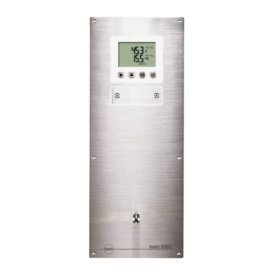
4 Transmitter 4.2. Product description 4.2.1. At a glance 1 Sealing plugs on the positive pressure test connection (Ø 4 mm) 2 Sealing plugs on the negative pressure test connection (Ø 4 mm) 3 Socket for service plug 4 Display (optional) 5 Keys (only with optional display) 6 Test rods for the analog... -
Page 14: Usable Probes
(Ø 6.4 mm) 17 Positive pressure connection (Ø 6.4 mm ) 18 Probe socket 4.2.2. Usable probes The testo 6383 transmitter can be used with the following probes: Probes Article no. Characteristic Integrated KMAT option Wall probe version; accuracy to ±1 % RH;... -
Page 15: Display And Keypad
-40 to +356 °F, sensor soldered 4.2.3. Display and keypad The display option allows operation of the testo 6383 transmitter via the display and four keys. The LCD display consists of two 7-segment lines for displaying readings and units and of an information line (for status messages, for example). -
Page 16: Analog Outputs
4 Transmitter 4.2.6. Analog outputs As analog outputs, the testo 6383 has either • 1 or optionally 3 current outputs of 0 to 20 mA (4-wire)/4 to 20 mA (4-wire) or • 1 or optionally 3 voltage outputs of 0 to 1 V/0 to 5 V/0 to 10 V (4-wire). - Page 17 4 Transmitter 1 The measuring range: The maximum sensor performance is in this range. Values outside of the measuring range are displayed via messages, for example. Measuring range, see table (below). 2 Standard scaling: The output signals are assigned to this measuring range as standard: ◦...
- Page 18 WMO relative % RH humidity Mixture humidity % RH For constant use in high humidity (> 80% rF at ≤ 30°C for > 12 h, > 60% rF at > 30°C for > 12 h), please contact us via www.testo.com/service-contact...
-
Page 19: Alarm Handling
The testo 6383 monitors limit values with the help of relays. If a reading is outside the limit values, a relay to be specified by the user is switched. -
Page 20: Commissioning
4 Transmitter 4.3. Commissioning 4.3.1. Mounting preparations... -
Page 21: Connecting The Instrument
4 Transmitter 1. Create a wall opening (approx. 120 mm x 220 mm) at the mounting location. 2. Hold 6383 in assembly position and mark the drill holes. 3. Drill holes suitable for the screws to be used. 4. Connect 6383. -
Page 22: Connecting Voltage Supply And Analog Outputs
4 Transmitter 4.3.2.2. Connecting voltage supply and analog outputs Terminal strip for voltage supply and analog outputs, item (1) of overview of terminals Wiring diagram for 4-wire system (0 to 20 mA/4 to 20 mA/0 to 1 V/0 to 5 V/0 to 10 V) 1 1 or 3 channels, 0 to 20 mA/4 to 20 mA max. -
Page 23: Connecting The Relay Outputs
4 Transmitter 2. Strip the cable ends, clamp wire end ferrules on and screw down with voltage terminals/channel terminals. 3. Tie together each of the two adjacent cores using a cable tie. 4. Attach terminal strip for voltage supply and analog outputs. 4.3.2.3. - Page 24 4 Transmitter to one another using a cable tie (3). • The insulation of the cable must be fed at least 5 mm (4) into the relay tray up to the elevated part. Use of relay as NC contact (NC = normally closed) 1 Alarm/status light (example of installation) 2 250 V AC/DC, 3 A...
- Page 25 4 Transmitter Use of relay as NO contact (NO = normally open) 1 Alarm/status light (example of installation) 2 250 V AC/DC, 3 A The busy light (alarm/status light) only comes on when the relay is switched (closed). Monitoring the functionality of the alarm circuit is therefore not possible with this switching operation.
-
Page 26: Connecting Pressure Connections
4 Transmitter 4.3.2.4. Connecting pressure connections Illustration shows delivery status Use of front pressure connection 1. Remove hose from hose holder (2) and connect to overpressure (3) or underpressure (1) connection. 2. Connect remaining pressure connection to (3) or underpressure potential (1) with additional hose. -
Page 27: Closing The Instrument
4 Transmitter 4.3.2.5. Closing the instrument 1. Connect probe. • Version with integrated humidity probe: 1. Insert probe into probe socket. 2. Guide probe through opening of front plate. 3. Tighten screw at opening. • Version with external humidity probe: >... -
Page 28: Ethernet Communication
4 Transmitter 5. Pull sealing frame (1) over the edge of the 6383. 6. Screw on 6383. Initially, only tighten the screws slightly. When all screws are in position, also align 6383 and tighten the screws. 7. Seal 6383 using a measure appropriate for the installation point (e.g. -
Page 29: Mains Connection
(transmitter accessory) or via the configuration menu of testo Saveris (testo Saveris Ethernet Assistent). 1. Set the IP address with the P2A software (see Using the software, page 116) or with the testo Saveris Ethernet Assistent (see instruction manual). 2. Remove service plug. Using Saveris >... -
Page 30: Integration Into Customer's Ethernet System
3. Select the project to be opened from tthe tree structure. 4. Confirm with [OK]. The program window Testo Saveris software is displayed in the foreground with the selected data set. 4.3.3.4. Integration into customer's Ethernet system... - Page 31 • Status and status messages (testo 6383) • Alarm messages (testo 6383) • Service hour counter (testo 6383 and probe) as well as the reading and writing of the: • Adjustment data (testo 6383) • Configuration data of analog outputs (testo 6383) •...
- Page 32 4 Transmitter XML codes (download) The table of xml-codes is available for download www.testo.com/download-center (requires registration). Description Parameter Answer (see Appendix) /data/getserialnumber Read off serial number of serialnumber.xml connected transmitter param=0 (for transmitter) /data/getidentification Read off type of identification.xml connected transmitter/...
- Page 33 4 Transmitter Upload XML documents Description Parameter Post Answer (see Appendix) /config/setusersettings Perform settings of usersettings.xml usersettings.xml transmitter param=0 (adjustment /config/setcalibration Set adjustment data of calibration.xml calibration.xml set 1) transmitter param=1 (adjustment set 2) param=2 (adjustment set 3) param=0 (relay 1) /config/setreldefinition Set relay information reldefinition.xml reldefinition.xml param=1 (relay 2)
- Page 34 4 Transmitter XML tag Description Type cal_minscale Scaling value Numerical, decimal number cal_maxscale Scaling value Numerical, decimal number Elements in collectivealarm.xml XML tag Description Type colalarmtable Base element. Contains the child elements alarm_numbers, alarm alarm_numbers Number of alarm messages Numerical, whole number alarm Parent element.
- Page 35 4 Transmitter Elements in identification.xml XML tag Description Type ident Base element. Contains the child element device_id device_id Transmitter type Numerical, whole number Elements in laststatusmessage.xml XML tag Description Type mufmsg Base element. Contains the child elements msg, sn, hours Status message ASCII Serial number...
- Page 36 4 Transmitter XML tag Description Type Status of relay relay_status Numerical, whole number 0 = off 1 = on Switch point: Switch point: sw_point_charact Numerical, whole number 0 = low-limit monitoring 1 = high-limit monitoring sw_point_value Switch point Numerical, decimal number hysteresis_value Hysteresis Numerical, decimal number...
- Page 37 4 Transmitter XML tag Description Type Auto OFF background lighting setting_display Numerical, whole number 0 -> background lighting auto off 1 -> background lighting stays on Brightness of background lighting backlight Numerical, whole number 0 to 9 (0 = off, 9 = max.) Display contrast contrast Numerical, whole number...
- Page 38 4 Transmitter XML tag Description Type channel_info Parent element. Contains the child elements connector_info, channel_type measurement_value See general elements meas_status Parent element. Contains the child elements min, max, mean connector_info Channel (transmitter/probe) ASCII channel_type Parameter details ASCII min. Minimum reading Numerical, decimal number max.
- Page 39 2 0= relay 3 is not set 1=relay 3 is set 3 0=relay 2 is not set 1=relay 2 is set 4 0=relay 1 is not set 1=relay 1 is set More information can be found in the download area at www.testo.com.
-
Page 40: Adjusting The Instrument
4 Transmitter 4.3.3.5. Adjusting the instrument The testo adjusting concept allows the entire signal chain from the sensor signal (probe) and the digital signal (within the transmitter) through to the analog signal (transmitter output signal) to be adjusted (see diagram). -
Page 41: Overview: Adjustment Keys And Test Contacts
The reference condition can be measured using a precise handheld instrument (e.g. testo 400/650 with precision humidity probe) or be created in an air conditioning cabinet. - Page 42 1. Connect testo handheld instrument 400/650 (1) with connected humidity reference probe (3) (order no. reference set 0699 3656/20) to the service interface (5) of the testo <v>T - Produktname MUF</v> via the adjustment adapter (2) (connected to probe socket 1 of the handheld instrument).
-
Page 43: 2-Point Adjustment (Humidity/Temperature)
6615 (trace humidity) probes. The reference conditions should be generated in a humidity generator to adjust these probes. In addition, these probes can also be adjusted at a third adjustment point by Testo Service. • testo 6614: third adjustment point at 90 % RH •... -
Page 44: Analog Output Adjustment
4. Service interface Adjusting analog outputs 1, 2 and 3 (optional) ✓ With testo 6383 with current output: Load of max. 500 Ω is connected to channel that is to be adjusted see Connecting voltage supply and analog outputs, page 22. -
Page 45: N-Point Adjustment (Pressure)
137) or enter it via the user menu (see Editing Main Menu Adjust, page 62). 3. Disconnect connections between the multimeter and the contacts of the testo 6383 and close the service cover. 4.3.3.10. n-point adjustment (pressure) With an n-point adjustment, the parameters at the 3-6 measurement points are adjusted to the reference value. -
Page 46: High-Humidity Adjustment For Testo 6614
4 Transmitter 4.3.3.11. High-humidity adjustment for testo 6614 With the testo 6614, the rear of the Testo humidity sensor is heated, creating a microclimate around the sensor (within the filter) that is constantly 5 K warmer than the actual process conditions. -
Page 47: Self Adjustment Of Testo 6615 Trace Humidity Probe
-60 °C To this end, a temperature sensor is fitted on the back of the testo 6615 which is used as a heater. A humidity and temperature value pair is taken in both the unheated and heated state. The deviation of the probe obtained from these pairs of values is automatically corrected. - Page 48 P2A software. • In the factory setting, a third adjustment point (-40 °C ) is approached for the testo 6615 in addition to the 2-point adjustment. This special adjustment can be performed again by your Testo Service team if necessary.
-
Page 49: Operation
4.4.1. Relationship between user menu and mini-DIN socket is active The testo 6383 can be parameterized using either the user menu or the P2A software (see volume 2, Parameterizing, adjusting and analyzing software (P2A software) page 112). The testo 6383 transmitter can only be operated via the display and keypad if the display option is available. - Page 50 4 Transmitter 1 Channel 1 display 2 Channel 2 display 3 Channel 3 display or for messages Four keys enable the user to navigate/scroll through the menus and enter/amend values and settings: Function/description • In Measuring Mode: changes to parameterization •...
-
Page 51: Overview Of The Testo 6383 User Menu
4 Transmitter 4.4.4. Overview of the testo 6383 user menu... - Page 52 4 Transmitter...
- Page 53 4 Transmitter...
-
Page 54: The Individual Main Menus
The individual main menus 4.4.5.1. Editing main menu of channel 1 An overview is given in Overview of the testo 6383 user menu, page 51). You can perform basic settings for channel 1. 1. In the Measuring Mode press SET, select... -
Page 55: Editing Main Menu Alarm
4 Transmitter 4.4.5.4. Editing Main Menu Alarm With the alarm, the relays, available as options, are programmed. In addition, the alarm statuses are shown on the display (top right) (even without relays). You can choose whether the alarm is to be used to monitor limit values or as a collective alarm. -
Page 56: Editing Main Menu Settings
If an alarm is assigned to the collective alarm, the relay is switched and a visual alarm can be issued via the display as soon as (at least) one of the warning or error messages of the testo 6383 transmitter (or the connected testo 6610 probe) becomes active. - Page 57 4 Transmitter You can edit settings for: • Display • Language • Code • Units ◦ Absolute pressure ◦ Area ◦ Temperature • Humidity process data ◦ H2O2 percentage by weight ◦ Humidity process pressure Editing display settings You can set the brightness and contrast of the display. 1.
- Page 58 4 Transmitter Selecting language You can select the language for the plain text line in the display. > Press SET, select required language with or , confirm selection with and return to Language. Only choose a language that you can understand well. Editing code settings You can set the access code (password).
-
Page 59: Editing Main Menu Analysis
4 Transmitter The selection passively vaporized actively vaporized in the submenu describes whether H generated by means of evaporation or is actively vaporized in the process. 3. Select passively vaporized actively vaporized with or and confirm with SET. 4. - Page 60 4. Accept setting by pressing and test with multimeter (minimum requirement: resolution 6.5 digits, at least 2-times more accurate than the 6383) as follows: Analog output 1, 2 or 3: Via test contacts under service cover, see diagram. 1 Positive test...
-
Page 61: Editing Message Main Menu
4 Transmitter 1. Read off the min./max. values of the three channels in succession with or and return to the Main Menu Analysis with ESC. with or or return to 2. Continue to Main Menu Message Measuring Mode with ESC. -
Page 62: Calling Up Main Menu Ident
4 Transmitter ON: Measurements are shown on the display in Measuring Mode. OFF: No messages shown on display. 8. Select with or and confirm selection with SET. 9. Return to Main Menu Message with ESC. with or or return to 10. - Page 63 4 Transmitter The 2-point adjustment for the adjustment points 11.3 %RH/75.3 %RH and 20 %RH/80 %RH is carried out via operation menu. Reference values for pressure can be entered for the n-point adjustment. Please refer to the description in n-point adjustment (pressure), page 45.
- Page 64 4 Transmitter Start self-adjustment The menu item self-adjustment is only visible when a testo 6615 probe is connected. 1. In the Measuring Mode press SET, select Main Menu Adjust with or and confirm selection with SET. 2. Select Self-adjust with ...
-
Page 65: Editing Reset Main Menu
4 Transmitter 8. Press SET. Read off multimeter display (e.g. 18,401 mA) and enter this value in the user menu. Do this by scrolling one digit to the right using and increasing the value of digit by 1 using . -
Page 66: Status, Warning And Error Messages
• Warning messages • Error messages The status and warning messages for the respective testo 6610 probes connected to the transmitter can be evaluated via the P2A software. All messages are stored in the transmitter with an operating hours stamp. Use the user menu (see Editing Message main menu, page 61) or the P2A software (see volume 2, Transmitter history, page 139) to view the message history. - Page 67 20 % RH 02130 2-point adjustment As part of the 2-point adjustment, 80 % an adjustment is performed at 80 % RH 02105 Self-adjustment For testo 6615 probe only: The active probe performs an automatic self- adjustment...
-
Page 68: Warning Messages
4 Transmitter 4.5.2. Warning messages Warning messages show an early warning or a current malfunction which may negatively impact measuring. Message Display Cause Remedying of fault 00809 Pressure too The process pressure Remove the transmitter high** exceeds the pressure from the process and intended for the take any necessary transmitter... - Page 69 2-point adjustment where necessary). If the problem persists, contact Testo Service 02809 Sensor early For testo 6617 probe Carry out visual warning* only: The cover inspection. If the mirror- electrode of the sensor like surface of the is damaged; this may...
-
Page 70: Transmitter Error Messages
T sensor broken The temperature sensor 0300D Contact Testo Service is damaged (sensor broken) 03105 Self-adjustment For testo 6615 probe Contact Testo Service error only: The automatic self-adjustment was faulty 03106 Adjustment error The adjustment of the Contact Testo Service... -
Page 71: Handling Alarm Messages
03000 Heat function For testo 6614 probe Contact Testo Service defective only: Heat function defective 4.5.4. Handling alarm messages Shown on the Can be used for... - Page 72 4 Transmitter Shown on the Can be used for Additional display collective alarm message end 1-point adjustment 2-point adjustment 11.3% 2-point adjustment 75.3 % Probe reset 2-point adjustment drift T ambient high T ambient low Supply voltage low T process high T process low Condensation Values less than...
-
Page 73: Namur Fault Conditions
4 Transmitter 4.5.5. Namur fault conditions If the faults named in the following table occur, the analog outputs output special values that enable a general fault warning in the higher-level control system. The values correspond to the "Namur" industry standard. Status Display Class... -
Page 74: Maintenance And Cleaning
4 Transmitter Status Display Class Analog output message in value in the display display Value above Reading Overrange 20.5 mA 20.5 mA 1.1 V 5.5 V 11 V max. scale Pressure too ooooo Overrange 20.5 mA 20.5 mA 1.1 V 5.5 V 11 V high Heat function -----... - Page 75 4 Transmitter Instrument surface ✓ Integrated humidity probe is protected by the plastic cap. • Clean the surface of the instrument with mild cleaning agents (e.g. washing-up liquid) and water. Only use gentle and standard cleaners. • Do not use any aggressive or chafing cleaning agents such as thinner, liquid scouring agent, wax, benzine, concentrated acids and lyes.
- Page 76 0970 6385 de 02 V01.12 V01.70-1 de Vol1...
Need help?
Do you have a question about the 6383 and is the answer not in the manual?
Questions and answers