TESTO 6381 Instruction Manual
Differential pressure transmitter
Hide thumbs
Also See for 6381:
- Instruction manual (178 pages) ,
- Instruction manual (84 pages) ,
- Instruction manual (92 pages)
Table of Contents
Advertisement
Quick Links
Advertisement
Table of Contents

Related Manuals for TESTO 6381


Summary of Contents for TESTO 6381
- Page 1 All manuals and user guides at all-guides.com testo 6381 Ethernet · differential pressure transmitter testo 6610 · Probes P2A software · Parameterizing, adjusting and analyzing software Instruction manual Volume 1 Testo-Direct info@Testo-Direct.ca 1.800.561.8187 www.
-
Page 2: Safety And The Environment
Pos: 8 /TD/Sicherheit und Umwelt/Sicherheit gewährleisten/MUF 63xx/Fachpersonal @ 3\mod_1234794940409_79.doc @ 26337 @ Any additional work must only be carried out by authorized personnel. Otherwise testo will not accept any responsibility for the proper functioning of the instrument after repair and for the validity of certifications. -
Page 3: About This Document
> At the end of its useful life, send the product to the separate collection for electric and electronic devices (observe local regulations) or return the product to Testo for disposal. Pos: 11 /TD/Überschriften/MUF/Zu diesem Dokument @ 3\mod_1234793991331_79.doc @ 26242 @ 1 About this document Pos: 12 /TD/Sicherheit und Umwelt/Zu diesem Dokument/Verwendung (Standard) @ 0\mod_1173775068554_79.doc @ 337 @ 5... -
Page 4: Table Of Contents
4.3.1. Inserting Ethernet module (order no. 0554 6656)...........21 4.3.2. Assembling the instrument................23 4.3.2.1. Wall mounting (for testo 6611, 6613, 6614, 6615, 6617 probes) ..23 4.3.2.2. Duct mounting (for testo 6612 probes) ..........24 4.3.3. Connecting the instrument ................25 4.3.3.1. Overview of terminals................27 4.3.3.2. - Page 5 Password protection ..................61 4.4.4. Structure of user menu .................. 61 4.4.5. Overview of the testo 6381 user menu ............63 4.4.6. The individual main menus ................66 4.4.6.1. Editing main menu of channel 1............66 4.4.6.2. Editing Main Menu Channel 2 (if this option is available) ....66 4.4.6.3.
-
Page 6: Transmitter
Furthermore, it is possible to issue an alarm for those responsible for the process, if necessary. Pos: 22 /TD/Leistungsbeschreibung/Lieferumfang/MUF 63xx/MUF 63xx Ethernet @ 3\mod_1234447308472_79.doc @ 25117 @ 3 4.1.2. Scope of delivery The scope of delivery of the testo 6381 transmitter includes the following: • Key cover •... -
Page 7: Accessories
All manuals and user guides at all-guides.com 4 Transmitter Pos: 23 /TD/Leistungsbeschreibung/Lieferumfang/MUF 63xx/Zubehör Übersicht 638x @ 3\mod_1234448071530_79.doc @ 25136 @ 3 4.1.3. Accessories The following accessories are available for the testo 6381 transmitter, amongst others: • Protection caps for probes •... - Page 8 Upon delivery and following a factory reset the readings are shown in the display in the unit that was ordered via the KMAT option Fxx, see Ordering options for 6381 transmitter (0555 6381), page 165. Humidity and temperature measuring range •...
- Page 9 Meas. cycle • 1/sec Interface • Mini-DIN for P2A software (parameterizing and adjusting software) and handheld testo 400/650 Voltage supply • 4-wire (separate signal and supply lines): 20 to 30 V AC/DC, 300 mA power consumption Maximum load 4-wire: 500 Ω (power output) •...
- Page 10 Ethernet connector, Harting PushPull connector and humidity probe are inserted and/or sealing plugs are inserted. Directives, standards and tests • EC Directive: 2004/108/EC • DIN 14644-4 • EN 61000-6-2 interference immunity • EN 61000-6-3 interference emission • EN 61326-1+A1+A2 Testo-Direct info@Testo-Direct.ca 1.800.561.8187 www.
-
Page 11: Dimensions
LED: 2 x green Warranty • Duration: 2 years • Warranty conditions: see website www.testo.com/warranty Pos: 25 /TD/Leistungsbeschreibung/Technische Daten/MUF 63xx/MUF 63xx Abmessungen @ 3\mod_1234450671494_79.doc @ 25194 @ 3 4.1.5. Dimensions Dimensions in mm with M20 cable couplings With NPT cable coupling With M plug-in connection Pos: 26 /TD/Überschriften/MUF/1.2/2.2 Produktbeschreibung @ 3\mod_1234258723551_79.doc @ 24008 @ 2... -
Page 12: Product Description
R3 and R4 relays 11 Eyelet for measuring point panel 12 M 20 x 1.5 screw connection*, e.g. R1 and R2 relays 13 Probe connector (testo 6610) 14 Upper part of housing Alternatively, NPT cable couplings or M plug-in... -
Page 13: Usable Probes
Pos: 28 /TD/Produktbeschreibung/Übersicht/MUF 63xx/Verwendbare Fühler 638x @ 3\mod_1234773201901_79.doc @ 25631 @ 3 4.2.2. Usable probes The testo 6381 transmitter can be used with the following probes: Probes Article no. Characteristic testo 6611 0555 6610-L11 Wall probe version; accuracy to ±1 % RH;... -
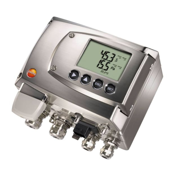
Page 14: Display And Keypad
Pos: 29 /TD/Produktbeschreibung/Übersicht/MUF 63xx/Display und Tastatur @ 3\mod_1234773965059_79.doc @ 25650 @ 3 4.2.3. Display and keypad The display option allows operation of the testo 6381 transmitter via the display and four keys. The LCD display consists of two 7-segment lines for displaying readings and units and of an information line (for status messages, for example). -
Page 15: Analog Outputs
Pos: 33 /TD/Produktbeschreibung/Übersicht/MUF 63xx/Analogausgänge 638x @ 3\mod_1234774341528_79.doc @ 25707 @ 3 4.2.6. Analog outputs As analog outputs, the testo 6381 has either • 1 or optionally 3 current outputs of 0 to 20 mA (4-wire)/4 to 20 mA (4-wire) or •... -
Page 16: Scaling
PLC. With the alarm definition, however, the physical measuring range limits are decisive. Pos: 36 /TD/Produktbeschreibung/Übersicht/MUF 63xx/Tabelle Skalierung MUF 638x @ 3\mod_1236343950039_79.doc @ 27502 @ Testo-Direct info@Testo-Direct.ca 1.800.561.8187 www. - Page 17 Parameter Unit Probes Physical Standard scaling of measuring range transmitter at 1013 hPa measuring range Temperature °C 6611 °F 6611 +158 +158 °C 6612 +150 +150 °F 6612 +302 +302 °C 6613, +180 +180 6614, 6617 Testo-Direct info@Testo-Direct.ca 1.800.561.8187 www.
- Page 18 % RH probes WMO relative % RH humidity Mixture dewpoint °C +100 +100 °F +212 +212 Degree of g/kg 13300 9500 humidity probes gr/lb 93000 66500 probes Enthalpy kJ/kg 99999 8000 BTU/lb 43000 3500 Psychrometer °C Testo-Direct info@Testo-Direct.ca 1.800.561.8187 www.
-
Page 19: Alarm Handling
The testo 6381 monitors limit values with the help of relays. If a reading is outside the limit values, a relay to be specified by the user is switched. -
Page 20: Commissioning
Inserting Ethernet module (order no. 0554 6656) The Ethernet module can be ordered retroactively as an accessory. It can easily be installed in the testo 6381 transmitter. ✓ The probe connector must be disconnected. 1. Loosen screw connection (1) of service flap and open the flap. - Page 21 First set the desired operating mode via the DIP switch (see Setting the Ethernet module, page 34) before fixing the instrument in place. 5. Set on upper part of instrument (5) and fix in place using the housing screws (6) provided in the accessories. Testo-Direct info@Testo-Direct.ca 1.800.561.8187 www.
-
Page 22: Assembling The Instrument
4.3.2. Assembling the instrument 4.3.2.1. Wall mounting (for testo 6611, 6613, 6614, 6615, 6617 probes) Attaching rear panel bracket 1. Remove locking screw (see item (4) of drawing below) and detach rear panel bracket from plastic bracket (see item (2) of drawing below). -
Page 23: Duct Mounting (For Testo 6612 Probes)
Pos: 42 /TD/Erste Schritte/MUF 63xx/Kanalmontage @ 3\mod_1234778800983_79.doc @ 25859 @ 4 4.3.2.2. Duct mounting (for testo 6612 probes) 1. Hold wall/duct bracket (order no. 0554 6651) (6) against duct wall (8) and mark drill holes for wall/duct bracket and probe shaft. -
Page 24: Connecting The Instrument
8. Insert probe connector (12) into socket until it engages. Pos: 43 /TD/Erste Schritte/MUF 63xx/Gerät anschließen Ethernet @ 3\mod_1234779843987_79.doc @ 25897 @ 35 4.3.3. Connecting the instrument Opening the instrument 1. Loosen screw connection (1) of service flap and open the flap. Testo-Direct info@Testo-Direct.ca 1.800.561.8187 www. - Page 25 (2). 3. Remove upper part of housing (3) and place on a clean surface. 4. Remove Ethernet module (A) from lower part of housing (4) and also place on a clean surface. Testo-Direct info@Testo-Direct.ca 1.800.561.8187 www.
-
Page 26: Overview Of Terminals
4 Insulating trough for relay 10 M 20 x 1.5 screw connection* board 5 Terminal strip for voltage 11 Eyelet for measuring point supply and analog outputs panel * Alternatively, NPT cable 6 Terminal board coupling or M plug-in connection Testo-Direct info@Testo-Direct.ca 1.800.561.8187 www. -
Page 27: Connecting Voltage Supply And Analog Outputs
2.7 mm² without wire end sleeves. • The supply line must be secured against exceeding 0.5 A. • An OFF switch must be installed in an easily accessible position close by and be marked as such. Testo-Direct info@Testo-Direct.ca 1.800.561.8187 www. -
Page 28: Connecting The Relay Outputs
4. Clean the connector of the probe line and the coupling of any foreign matter. Do not disconnect the connector of the probe line from the instrument for extended periods to protect against contamination. Testo-Direct info@Testo-Direct.ca 1.800.561.8187 www. - Page 29 (1). • It is recommended that you always tie 3 cores to one another using a cable tie (3). • The insulation of the cable must be fed at least 5 mm (4) into the tray. Testo-Direct info@Testo-Direct.ca 1.800.561.8187 www.
- Page 30 Use of relay as NO contact (NO = normally open) 1 Alarm/status light (example of installation) 2 250 V AC/DC, 3 A Testo-Direct info@Testo-Direct.ca 1.800.561.8187 www.
-
Page 31: Plug-In Connection Option
Transmitter housing Plug-in connections for power supply and channels M12 plug-in connection (5-pin) socket (item 1) View of the plug-in connections in the installed state from outside Assignment V 24- V 24+ + Ch1 - Ch1 Testo-Direct info@Testo-Direct.ca 1.800.561.8187 www. -
Page 32: Creating The Pe/Earthing Terminal
Pos: 48 /TD/Erste Schritte/MUF 63xx/PE-/Erdungsanschluss herstellen 638x @ 3\mod_1234788670248_79.doc @ 26049 @ 455 4.3.3.5. Creating the PE/earthing terminal As the testo 6381 has a metal housing, we recommend that the instrument be earthed. This can be done using the earthing terminal within the instrument (1) or the earthing terminal outside of the instrument (2). -
Page 33: Setting The Ethernet Module
• Saveris subscriber function (DIP switch no. 1 = on, DIP switch no. 2 = on), testo 6381 is used as a testo Saveris component. • XML server function (DIP switch no. 1 = off, DIP switch no. 2 = on), integration of the testo 6381 into the customer's Ethernet system. - Page 34 3. Set Ethernet module on lower part of housing (see arrow). 4. For the configuration of the Ethernet module, see following chapter. 5. If you do not wish to perform a configuration, close the transmitter. DIP switch no. 2 non-functional Testo-Direct info@Testo-Direct.ca 1.800.561.8187 www.
-
Page 35: Closing The Instrument
Pos: 50 /TD/Erste Schritte/MUF 63xx/Ethernet-spezifisch/Gerät schließen Ethernet @ 3\mod_1235986061555_79.doc @ 26965 @ 4 4.3.3.7. Closing the instrument 1. Place Ethernet module (A) on lower part of instrument (1). 2 Set on upper part of instrument (2) and fix in place using housing screws (3). Testo-Direct info@Testo-Direct.ca 1.800.561.8187 www. -
Page 36: Ethernet Communication
In general, the Ethernet module performs two functions: • a corresponding testo 6381 becomes a Saveris subscriber • a corresponding testo 6381 can be integrated into any Ethernet systems 4.3.4.2. Mains connection > Connect the network cable to the transmitter. -
Page 37: Led Status Displays
Saveris (testo Saveris Ethernet Wizard). 1. Set the IP address with the P2A software (see Using the software, page 131) or with the testo Saveris Ethernet Wizard (see instruction manual). 2. Disconnect service plug. 3. Disconnect the Ethernet module from the voltage supply. -
Page 38: Integration Into Customer's Ethernet System
Saveris Professional Client is installed • Select Saveris Viewer (limited functionality). The entry is available if Saveris Viewer is installed Testo Saveris software program window is opened with Select project dialogue. If the software will not start, check whether the testo... - Page 39 Path details of the IP address of the transmitter folder in which the and required URL (see table on the wget program is located usersettings XML file is the next page) located H:/wget/wget-complete-stable /wget --post-file= C:/usersettings.xml 254.169.100.100/config/ setusersettings Testo-Direct info@Testo-Direct.ca 1.800.561.8187 www.
- Page 40 • Status and status messages (testo 6381) • Alarm messages (testo 6381) • Service hour counter (testo 6381 and probe) as well as the reading and writing of the: • Adjustment data (testo 6381) • Configuration data of analog outputs (testo 6381) •...
- Page 41 /config/setreldefinition Set relay information reldefinition.xml reldefinition.xml param=1 (relay 2) of transmitter param=2 (relay 3) param=3 (relay 4) /config/setheatertime Set sensor heating heatertime.xml heatertime.xml information /config/setoptions Set options of options.xml options.xml transmitter /action/setresettm Not yet implemented resettm.xml Testo-Direct info@Testo-Direct.ca 1.800.561.8187 www.
- Page 42 Type of alarm ASCII Status of the alarm alarm_state Numerical, whole number 0 = alarm inactive 1 = alarm active Elements in firmwaredate.xml XML tag Description Type firmware_date Base element. Contains the child elements year, month, day Testo-Direct info@Testo-Direct.ca 1.800.561.8187 www.
- Page 43 ASCII, 8 characters hours Service hour counter in h Numerical, whole number Elements in onlinevalue.xml XML tag Description Type online_values Base element. Contains the child elements number_values, measurement_value number_values See general elements measurement_value See general elements Testo-Direct info@Testo-Direct.ca 1.800.561.8187 www.
- Page 44 ASCII, 8 characters Elements in status.xml XML tag Description Type mufstatus Base element. Contains the child elements statemsg, staterel, statecounter Status message statemsg Numerical, whole number See statemsg description Status relay staterel Numerical, whole number See staterel description Testo-Direct info@Testo-Direct.ca 1.800.561.8187 www.
- Page 45 Pressure process data, process humidity_process Numerical, decimal number humidity in % RH Pressure process data, process temperature_c_process Numerical, decimal number temperature in °C Humidity process data, absolute abs_pressure_pa Numerical, decimal number pressure in Pa * Child elements are optional Testo-Direct info@Testo-Direct.ca 1.800.561.8187 www.
- Page 46 The individual hardware options are bit-coded here. xxxx xxxx xxxx xxxx xxxx xxx1 2222 3334 1 0=2-wire 1=4-wire 2 free 3 0=4 to 20 mA 1=0 to 20 mA 2=0 to 1 V 3=0 to 5 V 4=0 to 10 V Testo-Direct info@Testo-Direct.ca 1.800.561.8187 www.
- Page 47 If statemsg = 0 there are no new messages. If statemsg != 0 xxxx xxxx xxxx xxxx xxxx xxxx 1234 5678 1 free 2 1=probe information 3 1= probe warning 4 1=probe error 5 free 6 1=transmitter information 7 1=transmitter warning 8 1=transmitter error Testo-Direct info@Testo-Direct.ca 1.800.561.8187 www.
-
Page 48: Adjusting The Instrument
Pos: 53 /TD/Erste Schritte/MUF 63xx/Gerät abgleichen @ 3\mod_1234789129795_79.doc @ 26068 @ 4 4.3.4.6. Adjusting the instrument The testo adjusting concept allows the entire signal chain from the sensor signal (probe) and the digital signal (within the transmitter) through to the analog signal (transmitter output signal) to be adjusted (see diagram). -
Page 49: Overview: Adjustment Keys And Test Contacts
Either the 1-point adjustment or 2-point adjustment is suitable for adjusting the sensor signal - digital signal chain. The testo 6381 transmitter has digital probes whose adjustment information is stored in the probes' internal memory. Both 1-point and 2-point adjustments can thus be carried out on another testo 6381 (e.g. -
Page 50: 1-Point Adjustment (Offset - Humidity/Temperature)
152) or • directly by means of a Testo handheld instrument (testo 400/650) (see description of how to proceed below). Please note that the 1-point adjustment is generally performed on the basis of the % RH and °C/°F parameters. Testo-Direct info@Testo-Direct.ca... - Page 51 1. Connect testo handheld instrument 400/650 (1) with connected humidity reference probe (3) (order no. reference set 0699 3656/20) to the service interface (5) of the testo 6381 via the adjustment adapter (2) (connected to probe socket 1 of the handheld instrument).
-
Page 52: 2-Point Adjustment (Humidity/Temperature)
11.3 % RH and 75.3 % RH. The reference conditions are created either by using testo adjustment salt pots (order no. 0554 0660) or in the humidity generator. In the 2-point adjustment, the deviations between the reading and the nominal value are minimized across the entire measuring range. - Page 53 All manuals and user guides at all-guides.com 4 Transmitter Pos: 58 /TD/Erste Schritte/MUF 63xx/testo MUF mit Abgleichtasten abgleichen @ 3\mod_1234791618180_79.doc @ 26144 @ 5 Adjusting testo 6381 using adjustment keys 11.3 % RH ⇒ 75.3 % RH 11.3 % RH ⇒ 75.3 % 1.5 h...
-
Page 54: Analog Output Adjustment
8. Contact ch. 2- Adjusting analog outputs 1 and 2 (optional) ✓ With testo 6381 with current output: Load of max. 500 Ω is connected to channel that is to be adjusted (see Plug-in connections for power supply and channels, page 32) ✓... -
Page 55: N-Point Adjustment (Pressure)
Performing analog adjustment, page 77). 3. Disconnect connections between the multimeter and the contacts of the testo 6381 and close the service flap. Pos: 60 /TD/Erste Schritte/MUF 63xx/Analogausgang 3 (optional) abgleichen 638x_Ethernet @ 3\mod_1237385522854_79.doc @ 30032 @ 5 Adjusting analog output 3 (optional) If the optional third analog output is to be adjusted, a cable connection to measure the analog value must be installed. -
Page 56: High-Humidity Adjustment For Testo 6614
3. Repeat step 2 for all of the measuring points. 4. Disconnect connections between the pressure sensor and the pressure connections of the testo 6381. Pos: 62 /TD/Erste Schritte/MUF 63xx/Hochfeuchteabgleich beim testo 6614 @ 3\mod_1235661029461_79.doc @ 26922 @ 4 4.3.4.12. High-humidity adjustment for testo 6614 Testo-Direct info@Testo-Direct.ca... -
Page 57: Self Adjustment Of Testo 6615 Trace Humidity Probe
(90 % RH) by Testo Service so that optimum accuracy is also achieved in the high humidity ranges. Pos: 63 /TD/Erste Schritte/MUF 63xx/Selbstabgleich des Restfeuchtefühlers testo 6615 @ 3\mod_1235661074070_79.doc @ 26942 @ 4 4.3.4.13. Self adjustment of testo 6615 trace humidity probe Conventional trace humidity probes show a steep rise in measuring uncertainty at low humidities. - Page 58 30 minutes daily. • In the factory setting, a third adjustment point (-40 °Ctd) is approached for the testo 6615 in addition to the 2-point adjustment. This special adjustment can be performed again by your Testo Service team if necessary.
-
Page 59: Operation
4.4.1. Relationship between user menu and mini-DIN socket is active The testo 6381 can be parameterized using either the user menu or the P2A software (see volume 2, Parameterizing, adjusting and analyzing software (P2A software) page 128). The testo 6381 transmitter can only be operated via the display and keypad if the display option is available. -
Page 60: Password Protection
Pos: 68 /TD/Produkt verwenden/MUF 63xx/Aufbau des Bedienmenüs 638x @ 3\mod_1234455236596_79.doc @ 25270 @ 3 4.4.4. Structure of user menu At the main menu level, the user menu comprises the following: • Main Menu Channel 1 • Main menu of channel 2 (if this option is available) Testo-Direct info@Testo-Direct.ca 1.800.561.8187 www. - Page 61 Selecting: scrolls through menus (downwards) or selectable alternatives • Editing: changes to next digit (to the right) • Selecting: scrolls through menus (upwards) or selectable alternatives • Editing: increases the value of the current digit by 1 Testo-Direct info@Testo-Direct.ca 1.800.561.8187 www.
-
Page 62: Overview Of The Testo 6381 User Menu
All manuals and user guides at all-guides.com 4 Transmitter Pos: 69 /TD/Produkt verwenden/MUF 63xx/Übersicht Bedienmenü @ 3\mod_1234510821302_79.doc @ 25303 @ 3 4.4.5. Overview of the testo 6381 user menu Testo-Direct info@Testo-Direct.ca 1.800.561.8187 www. - Page 63 All manuals and user guides at all-guides.com 4 Transmitter Testo-Direct info@Testo-Direct.ca 1.800.561.8187 www.
- Page 64 All manuals and user guides at all-guides.com 4 Transmitter Testo-Direct info@Testo-Direct.ca 1.800.561.8187 www.
-
Page 65: The Individual Main Menus
The individual main menus 4.4.6.1. Editing main menu of channel 1 An overview is given in Overview of the testo 6381 user menu, page 63). You can perform basic settings for channel 1. 1. In the Measuring Mode press SET, select... -
Page 66: Editing Main Menu Channel 3 (If This Option Is Available)
SET. Four alarms can be parameterized. 2. Select Alarm x with and confirm selection with SET. Using alarm to monitor limit values NO contact Monitoring minimum Monitoring maximum Hysteresis Hysteresis Limit value Limit value Testo-Direct info@Testo-Direct.ca 1.800.561.8187 www. - Page 67 If an alarm is assigned to the collective alarm, the relay is switched and a visual alarm can be issued via the display as soon as (at least) one of the warning or error messages of the testo 6381 transmitter (or the connected testo 6610 probe) becomes active.
-
Page 68: Editing Main Menu Settings
Absolute pressure ◦ Temperature • Pressure process data ◦ Absolute pressure ◦ Humidity ◦ Temperature ◦ Cross-section ◦ Pitot tube factor ◦ Correction factor • Humidity process data ◦ H2O2 percentage by weight ◦ Humidity process pressure Testo-Direct info@Testo-Direct.ca 1.800.561.8187 www. - Page 69 You can select the language for the plain text line in the display. > Press SET, select required language with , confirm selection with and return to language. Only choose a language that you can understand well. Testo-Direct info@Testo-Direct.ca 1.800.561.8187 www.
- Page 70 3. Scroll one digit to the right using and increase value of digit by 1 using . Confirm with or abort entry with ESC. 4. Return to Standard data with and use to continue Pressure process data. Testo-Direct info@Testo-Direct.ca 1.800.561.8187 www.
- Page 71 7. Edit humidity process pressure: Scroll one digit to the right using and increase value of digit by 1 using . Confirm with or abort entry with ESC. 8. Return to Change parameters with ESC. 9. Return to Main Menu Settings with ESC. Testo-Direct info@Testo-Direct.ca 1.800.561.8187 www.
-
Page 72: Editing Main Menu Analysis
4. Accept setting by pressing and test with multimeter (minimum requirement: resolution 6.5 digits, at least 2-times more accurate than the 6381) as follows: Analog output 1 or 2: Via test contacts under service flap, see diagram. 1 Channel 1... - Page 73 Main Menu Analysis with ESC. 2. Continue to Main Menu Message with or return to Measuring Mode with ESC. Pos: 75 /TD/Produkt verwenden/MUF 63xx/Hauptmenü Meldungen bearbeiten @ 3\mod_1234526541417_79.doc @ 25398 @ 4 Testo-Direct info@Testo-Direct.ca 1.800.561.8187 www.
-
Page 74: Editing Message Main Menu
Display of message with ON: Measurements are shown on the display in Measuring Mode. OFF: No messages shown on display. 8. Select with and confirm selection with SET. 9. Return to Main Menu Message with ESC. Testo-Direct info@Testo-Direct.ca 1.800.561.8187 www. -
Page 75: Calling Up Main Menu Ident
(°C/°F) for the 1-point adjustment. Please refer to the description in 1-point adjustment (offset - humidity/temperature), page 51 Reference values for pressure can be entered for the n-point adjustment. Please refer to the description in n-point adjustment (pressure), page 56 Testo-Direct info@Testo-Direct.ca 1.800.561.8187 www. - Page 76 Analog Adj. Ch. 1 with and confirm with SET. 3. Use to select Adj. Point 4. Press SET. Read off multimeter display (e.g. 5601 mA) and enter this value in the user menu. Do this by scrolling one digit Testo-Direct info@Testo-Direct.ca 1.800.561.8187 www.
- Page 77 6. Return to main menu Adjust with ESC. 7. Continue to main menu Reset with or return to Measuring Mode with ESC. Pos: 78 /TD/Produkt verwenden/MUF 63xx/Hauptmenü Reset bearbeiten 638x @ 3\mod_1234529155827_79.doc @ 25455 @ 4 Testo-Direct info@Testo-Direct.ca 1.800.561.8187 www.
-
Page 78: Editing Reset Main Menu
• Warning messages • Error messages The status and warning messages for the respective testo 6610 probes connected to the transmitter can be evaluated via the P2A software. All messages are stored in the transmitter with an operating hours stamp. Use the user menu (see Editing Message main menu, page 75) or the P2A software (see volume 2, Transmitter history, page 157) to view the message history. -
Page 79: Status Messages
All manuals and user guides at all-guides.com 4 Transmitter Pos: 81 /TD/Produkt verwenden/MUF 63xx/Status-Warnmeldungen/Statusmeldungen 638x @ 3\mod_1234534181195_79.doc @ 25474 @ 3 4.5.1. Status messages Status messages show the current operating status of the testo 6381. Message Display Description Sensor Message appears while the... -
Page 80: Warning Messages
As part of the 2-point adjustment, 75.3 % an adjustment is performed at 75.3 % RH 02105 Self-adjustment For testo 6615 probe only: The active probe performs an automatic self- adjustment Pos: 82 /TD/Produkt verwenden/MUF 63xx/Status-Warnmeldungen/Warnmeldungen 638x @ 3\mod_1234534609966_79.doc @ 25493 @ 3 4.5.2. - Page 81 2-point adjustment where necessary). If the problem persists, contact Testo Service 02809 Sensor early For testo 6617 probe Carry out visual warning* only: The cover inspection. If the mirror- electrode of the sensor like surface of the is damaged; this may...
-
Page 82: Transmitter Error Messages
0300D T sensor broken The temperature sensor Contact Testo Service is damaged (sensor broken) 03105 Self-adjustment For testo 6615 probe Contact Testo Service error only: The automatic self-adjustment was faulty 03106 Adjustment error The adjustment of the Contact Testo Service... -
Page 83: Handling Alarm Messages
03000 Heat function For testo 6614 probe Contact Testo Service defective only: Heat function defective Pos: 84 /TD/Produkt verwenden/MUF 63xx/Status-Warnmeldungen/Behandlung von Alarmmeldungen 638x @ 3\mod_1234769573888_79.doc @ 25573 @ 3 4.5.4. - Page 84 If at least one message is assigned to the collective alarm, the collective alarm is reset. If the collective alarm is set on a relay, the relay is also reset, meaning switched to its neutral position. Testo-Direct info@Testo-Direct.ca 1.800.561.8187 www.
-
Page 85: Namur Fault Conditions
Underrange 0 mA 3.8 mA min. scale Value above Reading Overrange 20.5 mA 20.5 mA 1.1 V 5.5 V 11 V max. scale Pressure too ooooo Overrange 20.5 mA 20.5 mA 1.1 V 5.5 V 11 V high Testo-Direct info@Testo-Direct.ca 1.800.561.8187 www. -
Page 86: Maintenance And Cleaning
(horn, light) or PLC. 4.6.2. Cleaning the instrument • Only clean the instrument carefully with a moist cloth. • Do not use aggressive cleaning agents. • Do not use any solvents. Testo-Direct info@Testo-Direct.ca 1.800.561.8187 www.
Need help?
Do you have a question about the 6381 and is the answer not in the manual?
Questions and answers