Sign In
Upload
Manuals
Brands
TESTO Manuals
Measuring Instruments
0555 6381
TESTO 0555 6381 Manuals
Manuals and User Guides for TESTO 0555 6381. We have
1
TESTO 0555 6381 manual available for free PDF download: Instruction Manual
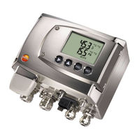
TESTO 0555 6381 Instruction Manual (178 pages)
Differential Pressure Transmitter, Probes
Brand:
TESTO
| Category:
Measuring Instruments
| Size: 13 MB
Table of Contents
Table of Contents
5
Safety and the Environment
3
About this Document
4
Table of Contents
5
Contents
5
Transmitter
7
Specifications
7
Functions and Use
7
Scope of Delivery
7
Accessories
8
Technical Data
8
Dimensions
12
Product Description
13
At a Glance
13
Usable Probes
14
Analog Outputs
15
Display and Keypad
15
Relay Board (Option)
15
Service Interface
15
Parameters
16
Scaling
17
Alarm Handling
20
Commissioning
21
Inserting Ethernet Module (Order No. 0554 6656)
21
Assembling the Instrument
23
Wall Mounting (for Testo 6611, 6613, 6614, 6615, 6617 Probes)
23
Duct Mounting (for Testo 6612 Probes)
24
Connecting the Instrument
25
Overview of Terminals
28
Connecting Voltage Supply and Analog Outputs
29
Connecting the Relay Outputs
30
Plug-In Connection Option
33
Creating the Pe/Earthing Terminal
34
Setting the Ethernet Module
35
Closing the Instrument
37
Ethernet Communication
38
Mains Connection
38
Types of Operation
38
LED Status Displays
39
Testo 6381 as Saveris Subscriber
39
Integration into Customer's Ethernet System
40
Adjusting the Instrument
50
Overview: Adjustment Keys and Test Contacts
51
1-Point Adjustment (Offset - Humidity/Temperature)
52
2-Point Adjustment (Humidity/Temperature)
54
Analog Output Adjustment
56
N-Point Adjustment (Pressure)
57
High-Humidity Adjustment for Testo 6614
59
Self Adjustment of Testo 6615 Trace Humidity Probe
60
Operation
62
Key Cover
62
Relationship between User Menu and Mini-DIN Socket Is Active
62
Password Protection
63
Structure of User Menu
63
Overview of the Testo 6381 User Menu
65
Editing Main Menu Channel 2 (if this Option Is Available)
68
Editing Main Menu Channel 3 (if this Option Is Available)
68
Editing Main Menu of Channel 1
68
The Individual Main Menus
68
Editing Main Menu Alarm
69
Editing Main Menu Settings
70
Editing Main Menu Analysis
74
Editing Message Main Menu
75
Calling up Main Menu Ident
77
Editing Main Menu Adjust
77
Editing Reset Main Menu
80
Status, Warning and Error Messages
80
Status Messages
81
Warning Messages
82
Transmitter Error Messages
84
Handling Alarm Messages
85
Namur Fault Conditions
87
Maintenance and Cleaning
88
Cleaning the Instrument
88
Maintaining the Instrument
88
Table of Contents
95
Contents
95
Testo 6610 Probes
98
Specifications
98
Digital Probes
98
Functions and Use
98
The Testo Humidity Sensor
98
Self-Diagnosis
99
Accessories
100
Design of the Probe
100
Product Description
101
Determining the Accuracy/Measuring Uncertainty
101
Overview of Probe and Filter Types
101
Probe Version
101
Ordering Options for Testo 6610 Probe (0555 6610)
102
Protection Caps
103
Testo 6611 Wall Probe
104
Testo 6612 Duct Probe
107
Testo 6613 Cable Probe
111
Testo 6614 Heated Cable Probe
114
Testo 6615 Trace Humidity Cable Probe (Self-Adjustment)
117
Testo 6617 Cable Probe (Self-Monitoring)
121
Self-Monitoring of Cover Electrode
122
Commissioning
125
Installing Testo 6613/6614/6615/6617 Probes
125
Installing the Probe
125
Installing the Testo 6611 Wall Probe
125
Installing the Testo 6612 Duct Probe
125
Connecting/Removing the Probe To/From the Transmitter
130
Maintenance and Cleaning
130
Replacing Filters/Protection Caps
130
Replacing the Filter/Protection Caps for Testo 6611 Wall Version
130
Replacing the Filter/Protection Cap for Testo 6612 Duct Version
131
Cleaning the Instrument and Filter/Protection Cap
132
Replacing the Filter/Protection Cap for Duct Versions
132
Replacing the Sensor
132
Parameterizing, Adjusting and Analyzing Software (P2A Software)
133
Specifications
133
Functions and Use
133
Scope of Delivery
134
System Requirements
134
First Steps
135
Installing P2A Software
135
Installing the Software/Driver
135
Installing USB Driver
135
P2A Software Upgrade
135
Starting the Program
135
Starting the Software
135
Activating the Connection with the Instrument
136
Establishing a Connection with the Instrument
136
Using the Software
137
User Interface
137
Changing Instrument/Parameter File
139
Editing Instrument/Parameter File
139
Copying and Pasting Parameters
152
Creating a New Instrument File
152
Opening the Parameter File
152
Saving Parameters
152
Analyzing/Testing the Instrument
153
Analyzing/Testing the Transmitter
153
Deleting Instrument/Parameter File
153
Carrying out Factory Reset
154
Testing Analog Output
154
Testing Switch Output Relays 1 to 4
156
Displaying Min./Max. Values
157
1-Point Adjustment
158
Adjusting the Transmitter
158
2-Point Adjustment
159
N-Point Adjustment
160
Adjusting the Analog Output
161
Transmitter History
163
Tips and Assistance
168
Questions and Answers
168
Accessories and Spare Parts
168
Ordering Options for 6381 Transmitter (0555 6381)
171
Advertisement
Advertisement
Related Products
TESTO 0555 6451
TESTO 0555 6452
TESTO 0555 6453
TESTO 0555 6454
TESTO 0554 2222
TESTO 0554 2160
TESTO 0554 0960
TESTO 0560 0110
TESTO 0560 4160
TESTO 0572 2165
TESTO Categories
Measuring Instruments
Thermometer
Data Loggers
Thermal cameras
Test Equipment
More TESTO Manuals
Login
Sign In
OR
Sign in with Facebook
Sign in with Google
Upload manual
Upload from disk
Upload from URL