TESTO 6681 Instruction Manual
Hide thumbs
Also See for 6681:
- Instruction manual (154 pages) ,
- Instruction manual (92 pages) ,
- Instruction manual (100 pages)

Related Manuals for TESTO 6681


Summary of Contents for TESTO 6681
- Page 1 6681 · Humidity transmitters testo 6610 · Probes P2A software · Parameterizing, adjusting and analyzing software Instruction manual Volume 2...
-
Page 3: Table Of Contents
2.2.4 testo 6613 cable probe .............. 88 2.2.5 testo 6614 heated cable probe ..........92 2.2.6 testo 6615 trace humidity cable probe (self-adjustment) ..95 2.2.7 testo 6617 cable probe (self-monitoring) ........99 2.3 Commissioning ..................103 2.3.1 Installing the probe ..............103 2.3.2... - Page 4 ................144 IPS AND ASSISTANCE 4.1 Questions and answers ............... 144 4.2 Accessories and spare parts ............... 145 4.2.1 Ordering options for testo 6681 transmitter (0555 6681) ....148 4.2.2 Ordering options for testo 6610 probes (0555 6610) ...... 152...
-
Page 5: Testo 6610 Probes
- 2.1 Specifications 73 testo 6610 probes 2.1 Specifications 2.1.1 Functions and use The plug-in, adjusted probes from the testo 6610 range are used in conjunction with the testo 6681 humidity transmitter. These measuring units are suitable for the following applications, for example: Process instrumentation •... - Page 6 - 2.1 Specifications 2.1.1.2 The Testo humidity sensor With the Testo humidity sensor, which has been in successful use and continually improved for more than twenty years, the focus has from the very beginning been on both accuracy parameters, namely measuring uncertainty and long-term stability.
-
Page 7: Design Of The Probe
Early warning when sensor corrosion is starting to develop • The testo 6617 probe is able to signal the first signs of corrosion. The probe can thus be changed at an early stage without interrupting the machine availability. -
Page 8: Accessories
Probe Protection cap, sensor underneath probe 2.1.3 Accessories The following accessories are available for probes in the testo 6610 range: Filters and protection caps (see chapter 2.2.1.4). • Calibration certificates according to ISO and DAkkS (see chapter 4.2, • Accessories and spare parts). - Page 9 GUM (Guide to the Expression of Uncertainty in Measurement/DIN V ENV 13005). All parts that make up the measuring uncertainty given by Testo are listed below. When comparing the measuring uncertainty/accuracy between manufacturers, which components are included is to be taken into account. In many cases, not all elements that contribute to measuring uncertainty are assessed, for example if the error contribution of the production adjustment is shown separately or not at all.
- Page 10 6610 - 2.2 Product description The measuring uncertainty of the probe includes the sensor and its electronics as well as the output of the digital measuring signal: 1. Linearity including scatter Systematic error and scattering of the components (due to manufacturing tolerances) 2.
- Page 11 Nxx Cable length N 00 Without cable (testo 6611) N 01 1 m cable length (testo 6613, 6614, 6615, 6617) N 02 2 m cable length (testo 6613, 6614, 6615, 6617) N 05 5 m cable length (testo 6613, 6614, 6615, 6617)
- Page 12 M 08 0554 6000 Filter for H atmospheres When ordering the probe, please use this filter code, cf. chapter 2.2.1.3, Ordering options for testo 6610 probes (0555 6610). When purchasing a replacement (filters only), please use this order number...
-
Page 13: Testo 6611 Wall Probe
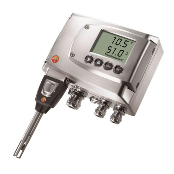
6610 - 2.2 Product description 81 2.2.2 testo 6611 wall probe The wireless testo 6611 probe is inserted into the testo 6681 humidity transmitter that is mounted on the wall and ready-wired. At a glance Filter (including: humidity and temperature sensor) - Page 14 6610 - 2.2 Product description Technical Data Refer to the charts below for the Parameters correlation between temperature Humidity (% °Ctd/°Ftd), etc. and accuracy. Temperature Length 70 mm As with length of 200 mm, but with Measuring range additional measuring error, specified...
- Page 15 % RH| as a factor of process humidity % RH % RH Temperature error as a factor of process temperature and temperature of electronics System error 6681 + probe, electronics 25 °C/+77 °F System error 6681 + probe, electronics -25 °C to +70 °C/-13 to 158 °F...
-
Page 16: Testo 6612 Duct Probe
6610 - 2.2 Product description 2.2.3 testo 6612 duct probe The testo 6612 probe measures the humidity and temperature in air ducts. At a glance Filter (including: humidity and temperature sensor) Probe shaft Wall/duct holder (accessories, Order no.: 0554 6651) - Page 17 Meeting the top accuracy requirements • Air duct applications for which a metal housing is required. • testo 6681 transmitter testo 6612 duct probe Technical Data Parameters ± (1,0 % RH + 0.007 x reading) for 0 to 90 % RH Humidity (% RH/°Ctd/°Ftd), etc.
- Page 18 L = approx. 200/300/500/800 mm please use cutting ring screw L – A = 165/265/465/765 mm connection (order no. 0554 1795). Measuring accuracy of testo 6612 duct probe ± Humidity error according to amount | % RH| as a factor of process...
- Page 19 - 2.2 Product description 87 Temperature error as a factor of process temperature and temperature of electronics System error 6681 + probe, electronics 25 °C/+77 °F System error 6681 + probe, electronics -25 °C to +70 °C/-13 to +158 °F...
-
Page 20: Testo 6613 Cable Probe
6610 - 2.2 Product description 2.2.4 testo 6613 cable probe The testo 6613 probe is used when the spatial separation of the transmitter and probe is required. At a glance Connector Probe cable Probe shaft Filter (including: humidity and temperature sensor) In the event of overpressures, the probe may become a projectile. - Page 21 6610 - 2.2 Product description 89 We recommend that the testo 6614 (heated) probe be used for continuous high-humidity processes. testo 6681 transmitter testo 6613 cable probe Technical Data ± (1,4 % RH + 0.007 x reading) for Parameters 90 to 100 % RH Humidity (% RH/°Ctd/°Ftd), etc.
- Page 22 A, see Table Filters, chapter 2.2.1.4. please use cutting ring screw connection (order no. 0554 1795). Measuring accuracy of testo 6613 cable probe ± Humidity error according to amount | % RH| as a factor of process humidity % RH...
- Page 23 - 2.2 Product description 91 Temperature error as a factor of process temperature and temperature of electronics System error 6681 + probe, electronics 25 °C/+77 °F System error 6681 + probe, electronics -25 °C to +70 °C/-13 to +158 °F...
-
Page 24: Testo 6614 Heated Cable Probe
- 2.2 Product description 2.2.5 testo 6614 heated cable probe The testo 6614 heatable probe is suitable for use in high-humidity processes in which there is the possibility of condensation for the probe. Please also see volume 1, chapter 1.3.3.5, for the functional principle of the testo 6614. - Page 25 • higher than +1.5 % RH, is to be expected. To prevent this error and ensure the highest measuring accuracy: Use condensation protector 0554 0166. testo 6681 transmitter testo 6614 heated cable probe Assembly distance max. 10 cm Temperature probe...
- Page 26 If installing probe under pressure, please use cutting ring screw connection (order no. 0554 1795). Measuring accuracy of testo 6614 heated cable probe ± Humidity error according to amount | % RH| as a factor of process humidity...
-
Page 27: Testo 6615 Trace Humidity Cable Probe (Self-Adjustment)
Temperature error as a factor of process temperature and temperature of electronics System error 6681 + probe, electronics 25 °C/+77 °F System error 6681 + probe, electronics -25 °C to +70 °C/-13 to +158 °F 2.2.6 testo 6615 trace humidity cable probe (self-adjustment) The testo 6615 probe corrects deviations in measurements by means of self- adjustment. - Page 28 6610 - 2.2 Product description At a glance Connector Probe cable Probe shaft Filter (including: humidity and temperature sensor) In the event of overpressures, the probe may become a projectile. For assembly, see Pressure resistance on the following page.
- Page 29 6610 - 2.2 Product description 97 testo 6681 transmitter testo 6615 trace humidity cable probe Technical Data Parameters ± 0,2 Ktf/K at 25 °C...50 °C/ 77 ° F...+122 °F Dewpoint (°Ctd/°Ftd), etc. ± 0,4 Ktf/K at 50 °C...120 °C/ Temperature +122 °...
- Page 30 %RH| dependent on the process dewpoint °Ctd Temperature error as a factor of process temperature and temperature of electronics System error 6681 + probe, electronics 25 °C/+77 °F System error 6681 + probe, electronics -25 °C to +70 °C/-13 to +158 °F...
-
Page 31: Testo 6617 Cable Probe (Self-Monitoring)
- 2.2 Product description 99 2.2.7 testo 6617 cable probe (self-monitoring) The testo 6617 probe is used if spatial separation of the transmitter and probe is required, particularly for media (gases, vapours) which can jeopardize/damage the humidity sensor (the testo 6617 has a self-monitoring and early-warning function for such applications). - Page 32 Connections (protected against corrosion) Dielectric layer The testo 6617 has a unique self-monitoring function. This allows early detection of damage to the sensor, e.g.: Mechanical damage (e.g. scratches) • Damage from aggressive gases (e.g. acids in aerosol form) •...
- Page 33 6610 - 2.2 Product description 101 testo 6681 transmitter testo 6617 cable probe (self-monitoring) Technical Data Parameters 0.02 % RH/K, dependent upon the electronics temperature Humidity (% RH/°Ctd/°Ftd) (with a deviation of 25 °C/+77 °F) Temperature Temperature Measuring range ±0.15 °C (0.27 °F)
- Page 34 % RH| as a factor of process humidity % RH % RH Temperature error as a factor of process temperature and temperature of electronics System error 6681 + probe, electronics 25 °C/+77 °F System error 6681 + probe, electronics -25 °C to +70 °C/-13 to +158 °F...
-
Page 35: Commissioning
The testo 6611 probe (wall version) simply has to be inserted into the socket of the testo 6681 transmitter. 2.3.1.2 Installing the testo 6612 duct probe A description of the duct mounting of the testo 6612 probe can be found in volume 1, chapter 1.3.1.2. 2.3.1.3 Installing testo 6613/6614/6615/6617 probes If used with these probes, the testo 6681 transmitter is mounted on the wall, see volume 1, chapter 1.3.1.1. - Page 36 When mounting the testo 6614 heated probe version, the temperature probe must be secured as close to the humidity probe as possible (max. 10 cm). An appropriate assembly tool is supplied with the testo 6614. Wall/duct holder Order no. 0554 6651...
- Page 37 6610 - 2.3 Commissioning 105 Duct mounting of probe Engage transmitter in the holder on the end of the duct probe Hole ∅ 12.5 mm Wall/duct holder Order no. 0554 6651 Only atmospheric processes up to approx. 1 bar positive pressure.
- Page 38 - 2.3 Commissioning Duct mounting of testo 6614 heated probe When mounting the testo 6614 heated probe version, the temperature probe must also secured at a distance of approximately 10 cm from the humidity probe. An appropriate assembly tool is supplied with the testo 6614.
-
Page 39: Connecting/Removing The Probe To/From The Transmitter
2.3.2 Connecting/removing the probe to/from the transmitter • Insert probe connector into socket of testo 6681 until it engages. The testo 6681 identifies which probe is connected. To remove the probe, the lock release button on the probe must be •... - Page 40 Screw on protection cap by hand, i.e. do not tighten it using a tool. 2.4.1.2 Replacing the filter/protection cap for testo 6612 duct version Do not damage the sensors when exchanging the filter/the protection cap and do not touch their surfaces!
- Page 41 6610 - 2.4 Maintenance and cleaning 109 Unscrew defective filter/protection cap from probe shaft and screw on new filter/protection cap. Screw on protection cap by hand, i.e. do not tighten it using a tool. Replace O-ring (6) if necessary. Push probe shaft into duct as far as the marking and fix position with screw (9).
-
Page 42: Cleaning The Instrument And Filter/Protection Cap
To maintain the extremely high accuracy of the testo 6610 probe, customers are not able to replace the sensor. Please contact your Testo Service team for this. -
Page 43: Parameterizing, Adjusting And Analyzing Software (P2A Software)
• This upgrade can be downloaded free of charge at any time from the • Testo homepage www.testo.com/download-center (requires registration). The software must only be bought one time, even for owners of several testo transmitters. 3.1.1 Functions and use In the P2A software, two different file types are used: The instrument and the parameter file. -
Page 44: System Requirements
P2A software - 3.1 Specifications Parameter file Parameter files are not tied to a specific individual transmitter and contain only parameter data/no history data. If you use various instruments of the same type, you can create parameter files once (e.g. by saving the appropriate instrument file as the parameter file) and transmit these onto the other instruments. -
Page 45: Scope Of Delivery
Click on [Finish] to complete the software installation. Installing USB driver You can download the USB driver under the following link: https://www.testo.com/download-center (Testo USB driver) If the installation program does not start automatically: > Open download folder and start USBDriver.exe. -
Page 46: Starting The Software
> Click on All Programs ( Windows 7, Windows 8, Windows ® ® ® Testo | P2A- Software. 7 the window User account control is In Windows ® opened when starting the software the first time > Click on Accept. -
Page 47: Using The Software
P2A software - 3.3 Using the software 115 3.3 Using the software 3.3.1 User interface Menu bar: Menu Command Explanation File Open Shows the Windows dialogue for searching and opening files. Save as Saves the parameters of an instrument or parameter file under a new name. - Page 48 P2A software - 3.3 Using the software Menu Command Explanation View Toolbar Activates/deactivates the toolbar or status bar. Status bar Check Checks the connections to a connected instrument instrument without the instrument having to be connections activated. A text file with the most important information on Service the computer and the software is opened via Display service data.
-
Page 49: Editing Instrument/Parameter File
P2A software - 3.3 Using the software 117 Function buttons: [Change parameterization] see chapter 3.3.2 [Test/analyze transmitter] see chapter 3.3.3 [Adjust transmitter] see chapter 3.3.4 [Transmitter history] see chapter 3.3.5 Dialogues on editing and testing the instrument are opened by means of the buttons. - Page 50 P2A software - 3.3 Using the software Unit/analog Explanation output All analog outputs are parameterized in this mask. Unit/analog Unit: 0 to 1 V/5 V/10 V or 4 to 20 mA. output Vertical: Current version of the analog output (cannot be (graphic) changed).
- Page 51 P2A software - 3.3 Using the software 119 Field Explanation Unit Selection of the physical unit. When changing the unit, standard values are set for scale minimum and maximum (see transmitter instruction manual for the scale final values). Caution! When changing the phys. unit, the relay limit values are set to the assigned default values.
- Page 52 P2A software - 3.3 Using the software Relay limit Explanation values 1 to 4 In this mask, the relays or display alarms are parameterized Only have the transmitter wired and connected by authorized personnel with the voltage disconnected. Relay x Four relays are available (optional).
- Page 53 P2A software - 3.3 Using the software 121 Field Explanation If switched to ON (NO contact) or OFF (NC contact) monitoring above the limit value; in the event of a subsequent undershooting of limit value minus hysteresis, it is switched to OFF (NO contact) or ON (NC contact). The graphic display in the centre of the screen refers to the relay wiring as a NO contact (ON).
- Page 54 P2A software - 3.3 Using the software Collective Explanation alarm Selection of the messages (error, etc.) that should result in a collective alarm (OR linkage). List field with Selection of which messages generated in the transmitter checkboxes should be signalled as the collective alarm via the corresponding relay.
- Page 55 P2A software - 3.3 Using the software 123 Basic Explanation settings Setting the absolute pressure and selection of the H evaporation process for the parameter °Ctm). Absolute The absolute pressure is included in the calculation of the pressure following units: °C or °F g/kg or gr/lb...
- Page 56 P2A software - 3.3 Using the software Display Explanation Setting the display functions (if a display is available on the transmitter). Continuous Display lighting is permanently switched on. display lighting Display lighting When a particular button on the instrument is pressed, the when button is display lights up for 10 seconds.
- Page 57 Valid password Display of the current password. Self- Explanation adjustment Parameterizing of testo 6615 probe, if this is used. (See volume 1, chapter 1.3.3.6, page 39 and chapter 2.2.7). Activate self- Perform adjustment of testo 6615 probe (auto- adjustment correction).
- Page 58 The original name (Instrument type, Serial number) is suggested with the current date/time as standard, e.g. "testo 6681 01234578 061120 1403.cfp". For a standard installation, the files are saved under "C:\Documents and Settings\All Users\Shared Documents\P2A Software". The path can differ depending on the version of the operating system.
-
Page 59: Analyzing/Testing The Transmitter
P2A software - 3.3 Using the software 127 You can also open parameter files that are stored in other directories. Click on File > Open in the menu bar. Select the storage location and click on the requisite file. Click on [Open]. The selected file is opened. - Page 60 P2A software - 3.3 Using the software Click on [Test/analyze transmitter]. The Properties of <Instrument type> <Serial number> dialogue is opened with the Test/analyze transmitter register. Perform action: Action Explanation Carry out factory Reset the unit, limit value and hysteresis parameters to reset: factory settings (see chapter 3.3.3.2).
- Page 61 P2A software - 3.3 Using the software 129 3.3.3.3 Testing channel 1/2/3 analog output The required instrument file is marked. Click on [Test/analyze transmitter]. The Properties of <Instrument type> <Serial number> dialogue is opened with the Test/analyze transmitter register. Mark channel and test values.
- Page 62 P2A software - 3.3 Using the software Field/button Explanation [Activate] The entered default value is forwarded to the corresponding analog output and to the test contacts by clicking. A warning informs that the value is being transmitted to the connected instrument in the event of existing cabling. Now check the analog output using a precise multimeter.
- Page 63 P2A software - 3.3 Using the software 131 Field/button Explanation Check the relay function (see volume 1, chapter 1.4.6.6). [Activate relay Close contact. A warning informs that the value is being transmitted to a connected PLC, external display, etc. in the event of existing cabling.
- Page 64 P2A software - 3.3 Using the software 3.3.3.5 Displaying min./max. values The transmitter saves the minimum or maximum value for each channel (measured since the last voltage supply or since the last manual reset). The required instrument file is marked. Click on [Test/analyze transmitter].
-
Page 65: Adjusting The Transmitter
P2A software - 3.3 Using the software 133 The values are reset to the default settings. Click on [OK] or [Cancel] to close the dialogue. 3.3.4 Adjusting the transmitter This function is used to adjust an attached instrument. The following adjustments may be carried out using the software: 1-point adjustment (offset) •... - Page 66 P2A software - 3.3 Using the software Field Explanation °C/°F Selection of the unit; only for temperature adjustment. Current Reading in °C/°F or % RH. reading Readings are updated every second. Reference Entry of the read-off value from the reference measuring value instrument.
- Page 67 P2A software - 3.3 Using the software 135 3.3.4.2 2-point adjustment Also see volume 1, chapter 1.3.3.3. Expose the reference measuring instrument and the instrument to be adjusted to the same constant conditions and wait for equalization period to lapse. Mark the instrument file of the connected instrument.
- Page 68 P2A software - 3.3 Using the software Field Explanation Current Reading in % RH. reading Readings are updated every second. Reference Entry of the read-off value from the reference measuring value instrument. Permissible entries: Lower adjustment point 10.3 to 12.3 % RH Upper adjustment point 74.3 to 76.3 % RH.
- Page 69 P2A software - 3.3 Using the software 137 3.3.4.3 Adjusting the analog output Connect precision multimeter (see volume 1, chapter 1.3.3.4). Mark the instrument file of the connected instrument. Click on [Adjusting the transmitter]. The Properties of <Instrument type> <Serial number> dialogue is opened with the Adjusting the transmitter register.
-
Page 70: Transmitter History
P2A software - 3.3 Using the software 3.3.5 Transmitter history Parameterizations, adjustment processes and messages that have occurred are registered in the transmitter with an operating hours stamp. In the history overviews (explained later in more detail), past processes and events can be made visible. - Page 71 P2A software - 3.3 Using the software 139 Parameterizati Explanation on history Date/time Format of the PC time is adopted from the settings of the operating system. User Name with which the user is logged into the operating system. "MUF" (= transmitter) if the change was performed at the instrument.
- Page 72 P2A software - 3.3 Using the software Adjustment Explanation histories Selection: 1-point adjustments/2-point adjustments/Analog adjustments. Date/time Format of the PC time is adopted from the settings of the operating system. User Name with which the user is logged into the operating system.
- Page 73 P2A software - 3.3 Using the software 141 Column Explanation Actual value 1-point adjustment: If no changes were performed, no before value is displayed. adjustment Offset from 1-point adjustment: Value before the adjustment. Offset to 1-point adjustment: Value after the adjustment. Offset 2-point adjustment: Difference between target and actual value reported by instrument.
- Page 74 P2A software - 3.3 Using the software Error/status Explanation messages The table is shown only for error and status messages that were generated in the transmitter and were transferred and saved there via the connection to the P2A software. Format of the PC time is adopted from the settings of the Date/time operating system.
- Page 75 P2A software - 3.3 Using the software 143 The printing job is automatically sent to the default printer for the operating system. The printout can be edited using [Set up printer…]. Click on [OK] or [Cancel] to close the dialogue.
- Page 76 When does a stable current reading After approx. 20 seconds appear? If we could not answer your question, please contact your dealer or Testo Customer Service. For contact data, see back of this document or web page www.testo.com/service-contact...
- Page 77 4.2 Accessories and spare parts 145 4.2 Accessories and spare parts An overview of the probes that can be used with the testo 6681 can be found in chapter 1.2.2. Designation Article no. Interface and software P2A software (parameterizing, adjusting, analyzing) incl. USB...
- Page 78 146 4.2 Accessories and spare parts Dewpoint measurement (only with testo 6615) Pre-filter for the protection of the measurement chamber and sensor 0554 3311 from contamination Precision chamber for adjustable flow impact 0554 3312 Ethernet Ethernet module for installation by customer...
- Page 79 4.2 Accessories and spare parts 147 Calibration Standard ISO calibration certificate, transmitter + probes 0520 0176 Special ISO calibration certificate, transmitter + probes 0520 0066 Standard DAkkS calibration certificate, transmitter + probes 0520 0276 Special DAkkS calibration certificate, transmitter + probes 0520 0236 ISO- calibration certificate humidity, probes 0520 0076...
- Page 80 148 4.2 Accessories and spare parts 4.2.1 Ordering options for testo 6681 transmitter (0555 6681) Order code Characteristic Version Currently no further selection of variants Bxx Analog output 4 to 20 mA (2-wire, 24 VDC) (not with relay, not with...
- Page 81 4.2 Accessories and spare parts 149 Order code Characteristic Channel 1 Unit % RH/Min/Max °C/Min/Max °F/Min/Max °Ctd/Min/Max °Ftd/Min/Max g/kg /Min/Max gr/lb /Min/Max /Min/Max gr/ft /Min/Max /min/max °C /Min/Max (wet bulb) °F /Min/Max (wet bulb) kJ/kg /Min/Max (enthalpy) hPa /Min/Max (water vapour partial pressure) inch H2O/Min/Max (water vapour partial pressure) % Vol / min / max Channel 2 Unit...
- Page 82 150 4.2 Accessories and spare parts Order code Characteristic % Vol / min / max Relay without relay 4 relay outputs, limit value monitoring 4 relay outputs, channel 1 limit values and collective alarm Optional 3rd analog output no optional 3rd analog output % RH/Min/Max °C/Min/Max °F/Min/Max...
- Page 83 4.2 Accessories and spare parts 151 Order code Characteristic Instruction manual languages German/English instruction manual French/English instruction manual Spanish/English instruction manual Italian/English instruction manual Dutch/English instruction manual Japanese/English instruction manual Chinese/English instruction manual...
- Page 84 Cable length N 00 Without cable (testo 6611) N 01 1 m cable length (testo 6613, 6614, 6615, 6617) N 02 2 m cable length (testo 6613, 6614, 6615, 6617) N 05 5 m cable length (testo 6613, 6614, 6615, 6617)
- Page 85 4.2 Accessories and spare parts 153 Order code Characteristic Probe length approx. 500 mm (testo 6612, 6613, 6614, P 50 6615, 6617) P 80 Probe length approx. 800 mm (testo 6612, 6613)
- Page 86 Testo SE & Co. KGaA Celsiusstr. 2 79822 Titisee-Neustadt Germany Tel.: +49 7653 681-0 E-Mail: info@testo.de www.testo.com 0970 6681 en 06 Vol2...
Need help?
Do you have a question about the 6681 and is the answer not in the manual?
Questions and answers