Table of Contents
Advertisement
Quick Links
Advertisement
Table of Contents
Troubleshooting

Related Manuals for Belarus 2022.6


Summary of Contents for Belarus 2022.6
- Page 1 BELARUS 2 0 2 2 . 6 2022.6-0000010 OM OPERATOR’S MANUAL 2014...
- Page 2 In view of Minsk Tractor Works policy directed to constant upgrading of produced goods, the construction of some units and parts of Belarus tractor may undergo changes which are not reflected in the present edition. The detailed information may be obtained from “BELARUS”...
-
Page 3: Table Of Contents
1.3 Tractor composition .....................15 1.4 Vibration level at the operator's working place of the tractor “BELARUS -2022.6”..18 1.5 Noise level at the operator's working place of the tractor “BELARUS -2022.6” ...18 1.6 Tractor and its components marking................18 2 CONTROLS AND INSTRUMENTS ................20 2.1 Layout of controls and instruments of the tractor ............20... - Page 4 2.21.5 Cab emergency exits ....................66 2.22 Seat and its adjustments....................67 2.22.1 General information ....................67 2.22.2 Adjustments of “BELARUS” seat ................67 2.22.3 Adjustments of “Grammer” seat ................68 2.23 Control of the transmission hydraulic system pump drive ..........69 2.24 Control of the pneumatic system compressor............69 2.25 Connector elements of the electrical equipment ............70...
- Page 5 4.12 Determination of total weight, loads on front and rear axles, tires holding capacity and the required minimum ballast...................136 4.13 Possibility of front loader installation ................138 4.13.1 General information ....................138 4.13.2 Safety measures while tractor “BELARUS-2022.6” operation with the loader installed..........................140 4.13.3 Information on tractor mounting holes..............142...
- Page 6 2022.6-0000010 OM 5 MAINTENANCE......................144 5.1 General instructions ....................144 5.2 Providing access to the components for maintenance services.........146 5.3 Maintenance procedure .....................147 5.4 Scheduled maintenance service operations ..............150 5.4.1 Maintenance service on a shift basis (SBMS) in every 8 – 10 hours of operation or per shift ..........................150...
- Page 7 2022.6-0000010 OM 6.14 Possible failures of the hydraulic lift linkage and guidelines for troubleshooting ..213 6.14.1 General information ....................213 6.14.2 Instructions for troubleshooting in HLL..............213 6.15 Possible failures in the electrical equipment and instructions for their troubleshooting ............................216 6.16 Possible failures of air-conditioning and cab heating systems and instructions for troubleshooting ........................218...
- Page 8 2022.6-0000010 OM Introduction The present manual is designed for studying the structure, operation rules and mainte- nance of tractors “BELARUS-2022.6”. Scrutinize this manual. It will help you to study the rules of correct operation and main- tenance. Failure to follow these instructions can lead to operator's injury or a tractor breakdown.
- Page 9 2022.6-0000010 OM The manufacturer uses standard international symbols regarding application of in- struments and control units. Given below are the symbols with indication of their meanings. see the manual; control manipulations; brake; fast; handbrake; slowly; audible beep; forward; alarm signaling;...
- Page 10 2022.6-0000010 OM front screen wiper; front driving axle drive; rear screen wiper and washer; fan; brake fluid level in main cylin- air filter clogged; der tanks; oil pressure in HSC engine start; beacon — road-train oil pressure in gearbox — external cylinder – retracting braking of gearbox —...
-
Page 11: Tractor Description And Operation
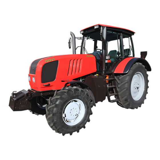
Physical configuration of tractor “BELARUS-2022.6” equipped with FPTO and FLL is shown in figure 1.1.2. Figure 1.1.1 – Basic configuration of tractor “BELARUS -2022.6” in basic configuration Figure 1.1.2 – Tractor “BELARUS-2022.6” equipped with FLL and FPTO (for the rest, see figure 1.1.1) -
Page 12: Technical Specifications
2022.6-0000010 OM 1.2 Technical specifications Main parameters and specifications of tractor “BELARUS -2022.6” are given in table 1.2.1. Table 1.2.1 Parameter Parameter value for tractor (specification) designation “BELARUS -2022.6” 1 Traction class according to GOST 27021 2 Rated traction force, kN 3 Engine а) model... - Page 13 2022.6-0000010 OM Table 1.2.1 continued Parameter Parameter value for tractor (specification) designation “BELARUS -2022.6” 8 Permissible load on axles, kN: а) on front b) on rear 9 Max weight of the trailer, kg а) without brakes 3500 b) with independent brake...
- Page 14 2022.6-0000010 OM End of table 1.1 Parameter Parameter value for tractor (specification) designation “BELARUS -2022.6” 19 Hydraulic system: а) pump displacement under crankshaft rated speed, l/min, at least b) safety valve operating pressure, МPа c) nominal volume factor, at least 20 Operating equipment: а) rear power take-off shaft:...
-
Page 15: Tractor Composition
2022.6-0000010 OM 1.3 Tractor composition Tractor framework is semi-frame. Undercarriage – front and rear wheels are driving, with pneumatic tires of low pres- sure. Front wheels are steering. Rear wheels can be twinned by means of a spacer. The tractor is equipped with a 4-stroke piston six-cylinder inner combustion engine with in-line vertical arrangement of cylinders, with direct injection of diesel fuel and com- pression ignition, corresponding to environmental requirements of Stage 4. - Page 16 2022.6-0000010 OM Rear axle: - with the main drive – a pair of bevel pinions with circular teeth; - with the hub drive – a pair of cylindrical gears; - with final drives – of planetary type; - with a differential – with mechanical blocking, and electrohydraulic control.
- Page 17 Drawbar hitches of a lift type, purchasing and mounting of which onto “BELARUS- 2022.6” tractors is allowed to be carried out by a customer individually, are as follows: - automated yokes KU2000/329NB33 or KU5410/329-33 (manufactured by company “Walterscheid”) with a spherical pin – for coupling with trailers and semi-trailers, as well as with agricultural machines based on trailers and semi-trailers;...
-
Page 18: Vibration Level At The Operator's Working Place Of The Tractor "Belarus -2022.6
2022.6-0000010 OM 1.4 Vibration level at the operator's working place of the tractor “BELARUS -2022.6” Vibration level at the operator's seat complies with the Council Directive 78/764/ЕEС. Values for vibration level are given in the EU type approval on each type of a seat. - Page 19 2022.6-0000010 OM Numbers of tractor components are given in table 1.6.1. Table 1.6.1 – Numbers of tractor components Version number of clutch housing Number of clutch casing assembly (to the left along tractor movement) Housing version Serial number number Number of gear box...
-
Page 20: Controls And Instruments
2022.6-0000010 OM 2. CONTROLS AND INSTRUMENTS 2.1 Layout of controls and instruments of the tractor Controls and instruments located in the tractor cab are shown in figure 2.1.1. Tractor controls and instruments Figure 2.1.1 –... -
Page 21: Switches Of The Instrument Board
2022.6-0000010 OM To the figure 2.1.1 – Layout of controls and instruments of the tractor: 1 – sun visor; 2 – dome light with a switch for cab lighting; 3 - place for radio receiver (car stereo) installation; 4 – air conditioner control panel; 5 – upper shield key switch block; 6 –... - Page 22 2022.6-0000010 OM The layout of key positions of the starter and instruments disconnect switch is given in figure 2.2.2 and on the informational plate of the switch. Figure 2.2.2 – Layout of key positions of the starter and instruments disconnect switch ATTENTION: THE REPEATED STARTER ENGAGEMENT IS POSSIBLE ONLY AFTER RETURN OF THE KEY INTO THE POSITION “0”...
- Page 23 2022.6-0000010 OM The windscreen wiper is activated by moving under-wheel switch lever 3 (fig. 2.2.1) from "off" position (“0” position according to fig. 2.2.4) into “a” position (first speed) or “b” (second speed). All positions shall be fixed. The windscreen washer is activated (in a non-fixed position) by moving the switch lever upward from any of three positions of the switch.
-
Page 24: Upper Shield Unit Of Button Switches
2022.6-0000010 OM 2.3 Upper shield unit of button switches Pressing cut-out button 1 (fig 2.3.1) activates a flash beacon (if available). Pressing cut-out button 2 activates two front working lights, mounted on the cab roof, and an indicating lamp built in the button. -
Page 25: Conditioner Control In The Heating Mode
2022.6-0000010 OM With the help of switch 1 you can change air flow by changing fan speed. Switch 2 al- lows to change temperature of cold and dry air coming from deflectors 6 (fig. 2.1.1) in the con- ditioning mode. -
Page 26: Cab Ventilation
2022.6-0000010 OM 2.4.3 Cab ventilation During the conditioner operation in the cooling and heating modes, cab ventilation is carried out at the same time. To make the conditioner operate only in the ventilation mode it is necessary to close the heater control valve, set switch 2 (figure 2.4.1.) in the position “0”... -
Page 27: Instrument Board
2022.6-0000010 OM 2.6 Instrument board Instrument board 13 (figure 2.1.1) includes six gauges with five signal lamps as shown in figure 2.6.1. Variant 1 Variant 2 1 – gauge to indicate oil pressure in the transmission system; 2 – signal lamp of emergency air pressure in the pneumatic system;... - Page 28 2022.6-0000010 OM The state of power supply system, depending on the position of gauge pointer on the scale, is given in table 2. 6. 1. Table 2.6.1 – The state of power supply system Zone on voltage gauge States of power supply system scale 5 (figure 2.6.1),...
-
Page 29: Pilot Lamps Unit
2022.6-0000010 OM 2.7 Pilot lamps unit 2.7.1 General information Pilot lamps unit 14 (figure 2.1.1) includes five lamps. The allocation scheme is shown in figure 2.7.1. 1 – pilot lamp to indicate that the air cleaner filter is clogged to the max. (orange color); 2 –... -
Page 30: Functioning Algorithm Of Pilot Lamp To Indicate Operation Of Heating Plugs
As a means of start facilitation, heating plugs (HP) are used in tractors “BELARUS – 2022.6” which are mounted in the cylinder unit head. For individual control of heating plug operation modes and indication of their operation, a heating plug control unit is used. -
Page 31: Integrated Indicator And Integrated Indicator Control Panel
(red color); 16 – pilot lamp to indicate low level of coolant (yellow color); 17- multifunction indicator. Figure 2.8.1 – Integrated indicator Note – On tractors “BELARUS-2022.6” the pilot lamp to indicate low level of coolant 16 is not used. While switching on the instrument scale lighting, i.e. while shifting the central dip- switch control into the position II “Instrument scale lighting, parking lights are on”... -
Page 32: Assignment And Operation Principle Of Integrated Indicator Gauges
2022.6-0000010 OM Control panel 16 (figure 2.1.1) allows to carry out manual programming of the indi- cator with buttons “Parameter” and “Value” (see figure 2.8.2), and also to change the mode of showing data entered on the multifunction display with “Mode” button. The “Mode”... - Page 33 1 – the digital symbol of the gear engaged (digits from 0 to 6) is displayed only on tractors with the CECS. Due to absence of the CECS on “BELARUS-2022.6» tractors the number of the gear engaged is not displayed on the multifunction indicator. The informa-...
- Page 34 2022.6-0000010 OM The following parameters are displayed in information field 2 (figure 2.8.3): - total elapsed engine time; - instant fuel flow; - on-board voltage; - remaining fuel volume; - time of running with remaining fuel; - rear PTO speed;...
-
Page 35: Pilot Lamps Of The Integrated Indicator
- pilot lamp to indicate increased on-board voltage 15 gets activated when the trac- tor on-board supply voltage goes up above 19V and goes out when the voltage falls below 17V; - pilot lamp to indicate low level of coolant 16 is not used on “BELARUS – 2022.6” tractors. -
Page 36: Description Of Testing The Integrated Indicator Performance
(II) by means of a special device (if provided). In case such a device is not pro- vided, the programming shall be performed by means of the above mentioned buttons. On “BELARUS-2022.6” tractors, the ХР1 connector is not provided. 2.8.5.2 The algorithm of the integrated indicator programming... - Page 37 - for “ZV”– from 12 to 99; - for “V” – from 0 to 1000. The list of programmed parameter values for tractors “BELARUS-2022.6” (graphic examples of parameter presentations and their values on the multifunction indicator in the programming mode) is given in Table 2.8.4.
- Page 38 PTO speed sensor. Considering this, any value, except for number “000”, can be set in parameter “KV2”. On tractors “BELARUS-2022.6» only the value of the side fuel tank volume (175 litres) shall be set, so the data about the operation time on the remaining fuel and etc. are formed without considering the fuel volume in the tank (the volume of the fuel tank under the cab is 130 litres).
-
Page 39: Information Display And Engine Control System Panel
2022.6-0000010 OM 2.9 Information display and engine control system panel 2.9.1 General information Information display 21 (figure 2.1.1) is designed to display engine actual parame- ters, indication of the engine electronic control system (EECS) faults and to display SCR parameters. - Page 40 2022.6-0000010 OM Monitor buttons 1, 2, 3, 4, 5 (figure 2.9.1) are of multifunctional purpose. When pressing any of buttons 2, 3, 4 during the monitor operation, an image of button panel 6 appears on the screen, the icons denoting the current functions of each button. Pressing button 1 on the moni- tor activates the main three-segment image on the screen.
- Page 41 2022.6-0000010 OM Table 2.9.1 – Lift of parameters of four-segment and graphic indication of engine operation Pos. Four-segment Graphic Parameters Symbol imaging imaging Electric voltage directly on terminals of information monitor connection, V Voltage on the accumulator battery terminals, measured by the engine...
-
Page 42: Engine Control System Panel
2.10 Steering 2.10.1 General information Tractor “BELARUS-2022.6” is equipped with hydrostatic steering control (HSC), de- signed for control of guide wheels turn and decrease of steering force while the feed pump is operating. If the feed pump fails to operate or to supply oil to the system control circuit (the engine is off or there is a failure in HSC), the turn is carried out in the manual mode at which significant steering effort is required. -
Page 43: Steering Wheel Adjustments
2022.6-0000010 OM 2.10.2 Steering wheel adjustments The steering wheel has the following adjustments: - according to the horizon tilt angle; - according to the height, along the steering shaft axis. To change height positioning of the steering wheel, do the following: - unscrew chuck 2 (figure 2.10.1) by 3-5 revolutions;... -
Page 44: Switching Of Ranges And Gears On Gb
2022.6-0000010 OM 2.14 Switching of ranges and gears on GB 2.14.1 General information Setting of the required gear is carried out by means of two levers and two buttons: lever for range switching 1 (figure 2.14.1), lever for gear switching 2, buttons for switching reduction unit passes 5 and 6. -
Page 45: Diagram Of Tractor Velocity
2022.6-0000010 OM 2.14.2 Diagram of tractor velocity The table of “BELARUS-2022.6” tractor velocity diagram (figure 2.14.2) on tires of basic configuration is attached to the cab right window. BELARUS-2022.6 Figure 2.14.2 – Diagram of tractor “BELARUS-2022.6” velocity... -
Page 46: Control Panel For Rear Axle Dl, Fda And Fpto Drives
2022.6-0000010 OM 2.15 Control panel for rear axle DL, FDA and FPTO drives 2.15.1 General information Elements of control panel for rear axle DL and FDA drive (basic configuration) are shown in figure 2.15.1. 1 – button for audible signal activation; 2 – annunciator of FDA drive activation; 3 –... -
Page 47: Front Power Take-Off Shaft Control
2022.6-0000010 OM 2.15.2 Front power take-off shaft control FPTO, if mounted against order, is controlled with switch 11 (figure 2.15.2) and button 9. The indication of FPTO engagement is carried out by annunciator 10. In the initial state the FPTO drive is disengaged by default, annunciator 10 is off. -
Page 48: Rear Axle Differential Lock Control
2022.6-0000010 OM ATTENTION: WHEN OPERATING ON ROADS WITH HARD SURFACE, IT IS RE- QUIRED TO DISENGAGE THE FDA DRIVE IN ORDER TO PREVENT INCREASED WEAR OF FRONT WHEEL TIRES! ATTENTION: VIOLATION OF RULES FOR USING FDA DRIVE OPERATION MODES MAY RESULT IN BREAKDOWN OF FDA PARTS AND OTHER PARTS OF TRANSMISSION! -
Page 49: Rear Pto Control
Switching between the rear PTO speed of 540 and 1000 rpm is carried out exclusively by installing the corresponding PTO shaft end extensions that have corresponding markings of “540” and “1000”. “BELARUS-2022.6” tractors do not have a special switch between the speeds of 540 and 1000 rpm of the rear PTO. -
Page 50: Control Of Lift Linkages
2022.6-0000010 OM 2.17 Control of lift linkages 2.17.1 General information on rules of RLL control RLL is controlled with control panel (figure 2.17.1) and remote buttons 4 and 5 (fig- ure 2.17.3). If there are any failures in the RLL electronic-hydraulic control system, a diag- nostics annunciator 5 (figure 2.17.1) displays information on the failure and, if necessary,... - Page 51 2022.6-0000010 OM Handle 11 has four positions: а) middle position – off; b) upper position – uplift; c) lower position – lowering (in operation – automatic control); d) moving the handle downward (nonfixed) from “в” position – implement penetra- tion (in this case the automatic control is off).
-
Page 52: Remote Buttons Of Rll Control System
(green color). Figure 2.17.2 – Rear lift linkage control panel PU-03 Note – RLL position indicator 11 (figure 2.17.2) is not used on “BELARUS-2022.6” tractors. The rules on using the RLL control panel PU-03 manufactured by “Izmeritel” plant are similar to the rules on using the RLL control panel produced by “BOSCH”... -
Page 53: Troubleshooting Of Rll Electronic Control System
2022.6-0000010 OM WARNING: WHEN USING REMOTE BUTTONS OF RLL CONTROL DO NOT STAND BETWEEN THE TRACTOR AND THE ATTACHED IMPLEMENT! TO PREVENT ACCIDENTS IT IS FORBIDDEN TO USE BUTTONS OF MECHANICAL SHIFTING OF ELECTRIC VALVES OF REGULATOR EHR23-LS! 1 – RLL remote control console; 2 – instruction plate on safety regulations; 3 – in- struction plate on RLL control diagram;... -
Page 54: Front Lift Linkage Control
2022.6-0000010 OM If light failures are detected, the troubleshooting annunciator shows a failure code, but the system remains controlled and is not blocked. In case of light failures, the RLL con- trol system operates improperly – there is no correct soil sensing. After elimination of the failure, the troubleshooting annunciator goes out. -
Page 55: Hll Valve Group Section Control (Remote Cylinders)
2022.6-0000010 OM 2.19 HLL valve group section control (remote cylinders) The control handles are located on the right side console of the cab. The handles have the following positions: “uplift”, “neutral”, “lowering”, “floating”. Handle 3 (figure 2.19.1) controls the left section of the valve group as viewed along tractor movement (left rear outlets of the hydraulic system). -
Page 56: Switching Unit And Electric Cutout Fuses
2022.6-0000010 OM а) for tractors with the Integrated block b) for tractors with the of “BOSCH” company hydraulic unit RP70-1523.1 Figure 2.19.2 – Diagram of HLL valve group outlets connection to outer consumers The outlet for the connection of the hydraulic motor drain pipe is shown in figure 2.19.3. - Page 57 2022.6-0000010 OM Your tractor can be equipped with two types of switching units - BKА-7.3722-02 or BK- 1-02 which are interchangeable. The place of unit 3 mounting is the cab, on the metallic bar of plastic shell fixing, be- tween instrument panel 4 and the windscreen.
- Page 58 2022.6-0000010 OM Diagram of fuses and relay location in the switching unit is shown in figure 2.20.3. а) Diagram of fuses and relay location in BKА-7.3722-02 b) Diagram of fuses and relay location in BK-1-02 Figure 2.20.3 – Diagram of fuses and relay location in the switching unit Tables of fuses and relay assignment shown in figure 2.20.3 are stuck from inside...
- Page 59 2022.6-0000010 OM Table 2.20.1 continued FU16 Horn 15А FU17 Front working lamps (on the handgrip) 15А Braking lights FU18 15А Power supply of terminal No.8 on the socket for the FU19 trailed agricultural implement connection (portable 15А lamp) Signal from the generator terminal “D” to the RLL FU20 30А...
- Page 60 2022.6-0000010 OM A set of spare fuses 5 (figure 2.20.2) installed on the front panel of the switching unit, includes spare fuses 2 (figure 2.20.4) with ratings 7,5А, 15А, 20А, 25А, 30А and for BKА-7.3722-02 - fuse removal tool 1. BK-1-02 is not completed with the fuse removal tool.
- Page 61 2022.6-0000010 OM To get an access to the fuses located near right accumulator 5 (figure 2.20.6), it is re- quired to open the hood. 1- fuse block; 2 – suspended fuse of 12V circuit of voltage converter, with rated value 25A;...
- Page 62 2022.6-0000010 OM The fuses, located between the engine and the cab, are shown in figure 2.20.9. 1 – power fuse of the starter relay and the additional AB charging circuit with rated value of 80А; 2 – power fuse of heating plugs with rated value of 80А; 3, 4 – power fuse of the switching unit with rated value of 60А;...
-
Page 63: Fuses For Electronic Systems Of Rear Axle Dl, Fda, Gb Reduction Unit, Fpto And Rll Control
2022.6-0000010 OM There are two spare accessory fuses 2 (figure 2.20.12) with rated value 60 A and 80 A in covers of fuse blocks 5 (figure 2.20.7 and figure 2.20.9). To get an access to spare accessory fuses 2, it is required to remove blind plug 3 out of fuse block cover 1. -
Page 64: Fuses For Engine Electronic Control System
2022.6-0000010 OM 2.20.4 Fuses for engine electronic control system The installation place of the fuse for the EECS constant supply (at any position of the AB switch) with rated value of 60A is shown in fig. 2.20.7. To get an access to the rest of the EECS cutout fuses, turn off screw 3 (figure 2.20.15) on cap 2 of side console 1 and open the cap. -
Page 65: Cab Locks And Handles
2022.6-0000010 OM 2.21 Cab locks and handles 2.21.1 Cab door locks Left and right doors of tractor cab are secured with locks 4 (figure 2.21.1). Lever 5 serves to open the left and right cab doors from inside the cab. Moving lever 5 backwards unlocks the door. -
Page 66: Rear Screen Opening
1 – handle; 2 –handgrip; 3 – rear screen. Figure 2.21.3 – Rear screen opening 2.21.4 Cab hatch opening Installation of two hatch variants for roof upper part is possible on tractors “BELARUS- 2022.6”: - hatch with a detent; - hatch with a handle. -
Page 67: Seat And Its Adjustments
- adjustment of the backrest tilt angle: a) For the seat “BELARUS 80-6800010” the backrest tilt angle is adjusted by means of hand wheel 3 within the range from minus 15° to plus 20°. To increase the backrest tilt angle, it is necessary to turn the hand wheel clockwise, to decrease it –... -
Page 68: Adjustments Of "Grammer" Seat
2022.6-0000010 OM 2.22.3 Adjustments of “Grammer” seat Against order your tractor can be equipped with “Grammer” seat (figure 2.22.2). 1 – handle for longitudinal adjustment; 2 – handle for adjustment according to the weight; 3 – indicator of seat adjustment according to the weight; 4 – handle for backrest tilt ad- justment. -
Page 69: Control Of The Transmission Hydraulic System Pump Drive
2022.6-0000010 OM 2.23 Control of the transmission hydraulic system pump drive The drive of the transmission hydraulic system pump is located on the left side of the gearbox body. 1 – lever; 2 – bolt; 3 – centre pin; 4 – gearbox pump drive assembly. -
Page 70: Connector Elements Of The Electrical Equipment
2022.6-0000010 OM 2.25 Connector elements of the electrical equipment 2.25.1 Socket to connect coupled agricultural equipment A standard seven-pin socket with an additional receiver to connect a portable lamp (figure 2.25.1) is intended to connect current consumers of a trailer or a trailed agricultural implement. -
Page 71: Fuel Tanks
2022.6-0000010 OM 2.26 Fuel tanks Two fuel tanks are mounted on “BELARUS-2022.6” tractors: - tank 2 (figure 2.26.1), attached to the tractor left side-member with the capacity 175 liters; - tank 4, mounted under the cab with the capacity 130 liters. -
Page 72: Indication Of Scr System Operation
2022.6-0000010 OM 2.27.2 Indication of SCR system operation To look through SCR system parameters, it is required to press any button of the moni- tor, except for button 5 (figure 2.9.1), when the monitor is in the display mode of engine pa- rameters. - Page 73 2022.6-0000010 OM SCR parameters are set forth on four pages. By pressing button 2 (figure 2.27.4) the pages with SCR parameters are turning: - first page – clauses 18, 19, 23 of table 2.9.1; - second page – clauses 20, 21, 24 of table 2.9.1;...
- Page 74 2022.6-0000010 OM In case of lowering reagent AdBlue level less than 28% of the tank filling volume, there pops up a symbol on the monitor in the flashing mode, shown in figure 2.27.7. In case of lowering reagent AdBlue level less than 4% of the tank filling volume, there pops up a symbol on the monitor in the mode of continuous glow, shown in figure 2.27.7.
-
Page 75: Intended Use Of Tractor
2022.6-0000010 OM 3 INTENDED USE OF TRACTOR 3.1 Safety measures while preparing tractor for operation Strict observance of safety requirements ensures safe operation of the tractor and improves its reliability and durability. Only persons not younger than 17, having a driving license for tractors of drawbar category 3.0, being briefed on accident and fire prevention, may be admitted to operate... -
Page 76: Tractor Use
3.2.2 Engine start and preparation for it To start the engine of tractor “BELARUS-2022.6”, do the following: engage the tractor parking brake; if required, fill in fuel and bleed the fuel delivery system to remove air from it;... - Page 77 2022.6-0000010 OM - after the heating plug pilot lamp goes out, start the engine, for which depress the clutch pedal and turn the key of starter and instruments switch from “I” position (“instru- ments on”) into position “II” (engine start);...
-
Page 78: Start Of Tractor Movement, Gb Shifting
Before starting the movement, define a necessary speed for tractor movement. The speed diagram of the tractor “BELARUS-2022.6” with tires of basic configuration is given in the instruction table attached to the cab right window and in subsection 2.14.2. “Tractor velocity diagram”. -
Page 79: Tractor Stop
2022.6-0000010 OM ATTENTION: IT IS NECESSARY TO PRESS CLUTCH PEDAL QUICKLY AND RE- LEASE SLOWLY, LITTLE BY LITTLE. THIS FACILITATES PRECISE GEAR SHIFTING AND BREAKAWAY. SLOWLY AND NON-FULLY PRESSING OF CLUTCH PEDAL LEADS TO CLUTCH SLEEPING AND CAUSES DIFFICULT AND NOISY GEARS SHIFTING IN GEAR BOX. -
Page 80: Leaving The Tractor
SPECIFIED IN TABLE 3.2.1! In their design and arrangement the front and rear PTO shaft end extensions (figure 3.2.1) of “BELARUS-2022.6” tractors conform to the regulations and standards applicable to PTO shafts of agricultural tractors. Parameters of shaft end extensions and specifications of the rear PTO operation when the independent drive is on, are given in Table 3.2.1. - Page 81 2022.6-0000010 OM Table 3.2.1 – Parameters of shaft end extensions and specifications of the rear PTO op- eration Parameters of shaft end exten- Type of PTO shaft end extension sions and FPTO and RPTO Type Type1 Type 1с Type 2 Type З...
- Page 82 2022.6-0000010 OM For operation with RPTO, remove protective cap 3 (figure 3.2.2) that covers shaft end extension 4, for which unscrew two fixing bolts 1. After finishing the operation with RPTO, it is required to mount the protective cap back to its place.
-
Page 83: Selection Of Optimal Inner Pressure In Tires Depending On Operational Conditions And Load On Tractor Axles
MD-214). Rates of admissible loads on single tires of tractors “BELARUS-2022.6” for selec- tion of operation mode at various tire inner pressure and speed are given in table 3.2.2. - Page 84 2022.6-0000010 OM Table 3.2.2 Load Speed Speed, Load on tire, G, kg, at inner pressure, kPa index * symbol * km/h Tire 1875 2050 2230 2405 2585 2850 1720 1845 2030 2210 2335 1500 1605 1765 1925 2035 420/70R24 kPa)
-
Page 85: Tire Inflation
2022.6-0000010 OM 3.2.8.2 Tire inflation Inflate tires through an air bleed valve of pressure regulator 1 (figure 3.2.3), for which do the following operations: - let the air out of balloon 3 of the pneumatic system through a condensate remov- ing valve;... -
Page 86: Rear Wheel Track Formation
2022.6-0000010 OM 3.2.9 Rear wheel track formation Tractor rear wheels are mounted on hub groups which consist of split conic bush- ings 3 and 4 (figure 3.2.4) and hub group housing 2. The bushings are tightened into the hub group housing with eight bolts 1 (M20) with a torque from 550 to 600 Nm, clenching the semiaxle. -
Page 87: Rear Wheel Twinning
2022.6-0000010 OM ATTENTION: AFTER BOLT TIGHTENING MAKE SURE THE BUTT ENDS OF UPPER AND LOWER BUSHINGS OVERHAND ONE IN RELATION TO THE OTHER FOR NOT MORE THAN 1...2 MM! DIAGRAM 1 DIAGRAM 2 Figure 3.2.5 – Rear wheel track setting Table 3.2.3 –... -
Page 88: Front Wheel Track Formation
2022.6-0000010 OM 3.2.11 Front wheel track formation The front wheel track is adjusted in stages by displacing the wheels from one side- board to the other and by changing a position of the wheel disk in relation to the rim. - Page 89 2022.6-0000010 OM End of table 3.2.4 Tractor track Variants of mounting the Disk offset Description of mounting К, mm disk and the rim Х, mm method (tire 420/70R24) The disk mates with the 1790 support outer surface. The disk mates with the 1890 support inner surface.
-
Page 90: Safety Measures While Tractor Operation
2022.6-0000010 OM 3.3 Safety measures while tractor operation 3.3.1 General safety measures while tractor operation The cab complies with category 2 under EN 15695-1:2009. This category cab en- sures protection against dust, but not against sprays and vapor – the tractor shall not be used under conditions, requiring protection against sprays and vapor. - Page 91 2022.6-0000010 OM Do not work under raised agricultural implements. Do not leave implements uplifted when stopping for a long time. Trailers attached to the tractor shall have a braking system, ensuring: - trailer brake during the movement; - brake engagement in case of trailer detachment from the tractor;...
- Page 92 2022.6-0000010 OM Do not operate the tractor with gages out of order. It is not allowed to inflate tires without pressure control. While coupling the tractor with agricultural implements, additionally observe safety measures concerning the use of these implements. Before coupling the tractor with agricultural implements, make sure the automatic grips of the lower and upper links of the RLL are clean and faultless.
-
Page 93: Fire Safety Measures
2022.6-0000010 OM 3.3.2 Fire safety measures The tractor shall be equipped with fire-fighting equipment, i.e. a shovel and a dry pow- der fire extinguisher. OPERATING THE TRACTOR WITHOUT FIRE-FIGHTING EQUIPMENT IS FORBID- DEN. The tractor must be filled with fuel and lubricants by a mechanic way and with the en- gine stopped. -
Page 94: Tractor Final Assembly And Run-In
2022.6-0000010 OM 3.4 Tractor final assembly and run-in 3.4.1 Tractor final assembly “BELARUS-2022.6” tractors are supplied to a consumer ready assembled, final as- sembly is not required. 3.4.2 Technical maintenance before tractor run-in Before placing a new tractor in operation, do the following: - wash the tractor, remove preservative lubricant (if any on the tractor);... -
Page 95: Technical Maintenance During Tractor Run-In
2022.6-0000010 OM Start the engine. Let the engine run at idle speed for five minutes with gradual in- crease of the rotation speed up to 1600 rpm, then run in under load for 30 operation hours. While carrying out a 30-hour run-in, follow the instructions below: - constantly inspect gage indications, operation of lubrication system, cooling sys- tem and power supply system. -
Page 96: Emergency Actions
2022.6-0000010 OM - check brake fluid level in the main cylinder tanks of hydrostatic clutch drives and in the tanks of service brakes, if necessary add it; - check and if required, adjust free movement of the clutch pedal, of the service and parking brakes control and the brake valve drive of pneumatic system;... -
Page 97: Coupling Of Implements
Selection and buying of agricultural implements (fertilizer distributors, plows, motor cultivators, harrows, seeding machines, rotary tooling and other implements) for tractors “BELARUS-2022.6” is carried out by the customer individually according to their needs, and with consideration of the implement and tractor performance specifications, and also local conditions i.e. -
Page 98: Types Of Implements Coupled With Tractor "Belarus -2022.6
COUPLED! 4.2 Types of implements coupled with tractor “BELARUS -2022.6” According to the type of coupling with tractors “BELARUS-2022.6” the implements are divided into the following types: - mounted implement is fixed in three points to the LL upper and lower links. The tractor can carry the weight of an implement in full. -
Page 99: Lift Linkage
MENTS, FOR PERFORMANCE OF DIFFERENT WORK WITH THE TRAVEL SPEED NOT MORE THAN 15 KM/H! RLL sizes and design of tractors “BELARUS-2022.6” make it possible to couple all implements having the corresponding dimensions of the coupling triangle connecting ele- ments shown in RLL diagram. - Page 100 2022.6-0000010 OM To ensure the required position of the implement, the following RLL vertical and hor- izontal adjustments by means of upper link, lifting rods and buckles are provided: 1. Adjustment of the upper link length. It is carried out in order to ensure equal soil penetration of operating parts (running depth levelling of operating parts located one after another in the direction of tractor movement).
- Page 101 2022.6-0000010 OM During operation with wide-cut implements in order to facilitate crossover contour following (seeding machines, cultivators and etc.) and reduce load on RLL, it is required to provide free movement in vertical plane of one lower link in relation to the other. To do this, adjust the lifting rods so that one lower link moves freely in vertical plane in relation to the other.
- Page 102 2022.6-0000010 OM PTO shaft end extension area Figure 4.3.2 Rear lift linkage diagramm of “LL-2” type Table 4.3.1 – Basic parameters and coupling dimensions of RLL Standard size (configuration) LL-3 LL-2 of the device (figure 4.3.1) (figure 4.3.2) 1 Category (acc. to ISO 730-1)
-
Page 103: Rll Components Adjustment Rules
2022.6-0000010 OM 4.3.3 RLL components adjustment rules 4.3.3.1 Buckles Buckles are used to limit side swaying of RLL lower links in transport and in operat- ing position. Your tractor can be equipped with telescopic turnbuckles. Buckles 2 (figure 4.3.3) are fixed with one end to eye lugs 3 of lower links 4. The other end of buckles with hinge joints is fixed into the brackets of buckles 1 with the help of pins. -
Page 104: Lifting Rods
2022.6-0000010 OM Setting of “buckle unlocked” shall be carried out in the following order: - turn guiding pin 2 for ≈90° and match the groove in guiding pin 2 with the hole in slide piece 4; - while rotating guiding pin 2, place the hole in slide piece 4 on the groove center (adjust the right and left buckles);... -
Page 105: Upper Link
2022.6-0000010 OM 4.3.3.3 Upper link Upper link is shown in Figure 4.3.6. The upper link length may be adjusted within 675 to 900mm. Adjustment of the upper link length shall be made in the following order: - unscrew counter nut 3 (figure 4.3.6);... -
Page 106: Mounting Of Implements To The Tractor Rll
2022.6-0000010 OM 4.3.3.5 Mounting of implements to the tractor RLL While mounting of implements to the tractor, make sure that there are no people in the area of implement mounting. Using RLL controls put down lower links to the required position and connect lower links hinge joints to the implement, and then connect upper link hinge joint by means of a pin. -
Page 107: Three-Point Front Lift Linkage
2022.6-0000010 OM 4.3.4 Three-point front lift linkage Front lift linkage (FLL) is mounted on tractor “BELARUS-2022.6” against order. Tractor with FLL is completed with front independent PTO, mounted on the front plane of bracket 4 (figure 4.3.9). FLL is mounted on the front plane of beam 3 and is fixed with additional plates 2 to the beam side surface. - Page 108 2022.6-0000010 OM IT IS FORBIDDEN TO OPERATE FLL WITH LOGGING BLADES AND FOR JACK- ING OF TRACTOR FRONT ELEMENT! Front lift linkage is a three-point lift linkage of category 2 according to ISO 730 and LL-2 according to GOST 10677. The diagram of FLL of configuration LL-2 is shown in fig- ure 4.3.10.
-
Page 109: The Rules Of Agricultural Implements Coupling To Fll
2022.6-0000010 OM 4.3.5 The rules of agricultural implements coupling to FLL Agricultural implements coupling to FLL is similar to RLL coupling. First it is necessary to place hinged joints of LL lower links grippers on a lower axle of the agricultural machine. It is required to approach the agricultural machine slowly, at the speed of not more than 3 km/h, with the lower links grippers as low as possible, until the grippers jaw is located under the hinge joints on the machine axle. -
Page 110: Drawbar Hitches
- drawbar hitches of semi-trailers have an adjustable support. Tractor “BELARUS - 2022.6” has a special-purpose rear mounting device of lift type in the form of vertical guiding plates with several openings, fixed to the rear joint face of the rear axle body. -
Page 111: Drawbar Hitch Dh-2V (Short Towing Yoke)
2022.6-0000010 OM 4.4.2 Drawbar hitch DH-2V (short towing yoke) Figure 4.4.1 – Installation variant diagram of DH-2V (short towing yoke) Table 4.4.1 – Basic parameters and coupling dimensions of DH-2V (short towing yoke) Standard size (configuration) of the device DH-2V (short towing yoke) 1. -
Page 112: Drawbar Hitch Dh-Зv (Long Towing Yoke)
2022.6-0000010 OM 4.4.3 Drawbar hitch DH-ЗV (long towing yoke) Figure 4.4.2 – Installation variant diagram of DH-ЗV (long towing yoke) Table 4.4.2 – Basic parameters and coupling dimensions of DH-ЗV (long towing yoke) Standard size (configuration) DH -3V (long towing yoke) 1. -
Page 113: Drawbar Hitch Dh-2R ("Python")
2022.6-0000010 OM 4.4.4 Drawbar hitch DH-2R (“python”) Figure 4.4.3 – Installation variant diagram of DH -2R (“python”) Table 4.4.3 – Basic parameters and coupling dimensions of DH -2R (“python”) Standard size (configuration) DH -2R (python) 1. Mounting location Rear lifting device 2. -
Page 114: Drawbar Hitch Dh-1М-01 (Draw Bar)
2022.6-0000010 OM 4.4.5 Drawbar hitch DH-1М-01 (draw bar) Figure 4.4.4 – Installation variant diagram of DH-1М-01 (draw bar) Table 4.4.4 – Basic parameters and coupling dimensions of DH -1М-01(draw bar) Standard size (configuration) DH -1М-01 (draw bar) 1. Variant First position Second position 2. -
Page 115: Drawbar Hitch Dh -1 (Crossbeam)
2022.6-0000010 OM 4.4.6 Drawbar hitch DH -1 (crossbeam) Lower link, right Lower link, left Figure 4.4.5 – Installation diagram of DH -1 (crossbeam) Table 4.4.5 – Basic parameters and coupling dimensions of DH -1 (crossbeam) Standard size (configuration) DH -1 (crossbeam) -
Page 116: Coupling Clevis Ku2000/329Nb33 And Coupling Clevis Ku5410/329-33
2022.6-0000010 OM 4.4.7 Coupling clevis KU2000/329NB33 and coupling clevis KU5410/329-33 Figure 4.4.6 – Diagram of mounting variants for coupling clevises KU2000/329NB33 and KU5410/329-33 Table 4.4.6 – Basic parameters and coupling dimensions of coupling clevis KU2000/329NB33 Standard size (configuration) Coupling clevis KU2000/329NB33... - Page 117 2022.6-0000010 OM 1 – center pin; 2 – handle for lifting center pin; 3 – handle; 4 – yoke rear wall; 5 – detent. Figure 4.4.7 – Coupling clevis KU2000/329NB33 To change the attaching points in the coupling clevis lifting device along the height, it is re- quired to turn handle 3 (figure 4.4.7), after which the coupling clevis shall come down and get fixed in...
-
Page 118: Piton-Fix Coupling Pb5329Nnb33
2022.6-0000010 OM 1 – center pin; 2 – handle; 3 – handle-detent for center pin; Figure 4.4.8 – Coupling clevis KU5410/329-33 To change the attaching points in the coupling clevis lifting device along the height, it is required to turn handle 2 (figure 4.4.8), after which the coupling clevis shall come down and get fixed in the next lower fasteners of the lifting device. - Page 119 2022.6-0000010 OM Table 4.4.8 – Basic parameters and coupling dimensions of Piton-Fix coupling PB5329NNB33 Standard size (configuration) Piton-Fix coupling PB5329NNB33 1 Mounting location Rear lifting device 2 Design features Tow pin located on the lifting device, with the possibility of height adjustment...
-
Page 120: Coupling Balls Ki8329Nb33 And Kb8329Nb33
2022.6-0000010 OM 4.4.9 Coupling balls KI8329NB33 and KB8329NB33 Figure 4.4.11 – Diagram of mounting variants for coupling balls KI8329NB33 and KB8329NB33 Table 4.4.9 – Basic parameters and coupling dimensions of the coupling ball KI8329NB33 Standard size (configuration) Coupling ball KI8329NB33... - Page 121 2022.6-0000010 OM 1 – ball; 2 – rest; 3 – handle; 4 – pin Figure 4.4.12 – Coupling ball KI8329NB33 To change the attaching points in the coupling ball lifting device along the height, it is required to turn handle 3 (figure 4.4.12), after which the coupling ball shall come down and get fixed in the next lower fasteners of the lifting device.
- Page 122 2022.6-0000010 OM Table 4.4.10 – Basic parameters and coupling dimensions of the coupling ball KB8329NB33 Standard size (configuration) Coupling ball KB8329NB33 1 Mounting location Rear lifting device 2 Design features Towing ball Ø80, located on the lifting device, with the possibility of height ad-...
-
Page 123: Usage Patterns Of Tractor Hydraulic System For Drive Of Operating Parts And Other Elements Of Hydraulically-Powered Coupled Machines And Implements
(uplift) of the operating parts. The main characteristics of tractor “BELARUS-2022.6” HLL for drive of operating parts and other elements of coupled hydraulically-powered implements and machines are shown in table 4.5.1. - Page 124 2022.6-0000010 OM Table.4.5.1 – Tractor “BELARUS-2022.6” hydraulic drive specifications Parameter designation Parameter value (characteristic) Side Rear 1 Paired hydraulic outlets Three pairs 2 Oil pipe of free drain into the tank One item 3 Oil consumption through hydraulic outlets, Up to 53...
-
Page 125: Front Ballast Weight
6 are fixed in housing with two strings 5. The housing with weights is fastened to spacer of ballast 2022-4235010. It is possible to order tractor equipped with additional ballast as well as to buy addi- tional ballast for already purchased “BELARUS-2022.6” tractor. - Page 126 2022.6-0000010 OM The diagram for mounting a kit of ballast weight assembled with a bracket is shown in figure 4.6.3. Information on how to mount ballast weights onto FLL is given in table 4.6.1. 1 – upper link; 2 – upper link tube handle; 3 – bracket with weights; 4 – lower links.
-
Page 127: Trailer Brake Drive
WHEELS AND PREVENTING THE TRACTOR FROM SELF-MOVEMENT! 4.7.2 Double-wire pneumatic drive for trailer brakes Tractors “BELARUS-2022.6” in basic configuration are equipped with a double-wire pneumatic drive providing brake control for trailers and agricultural machines, equipped with a double-wire pneumatic brakes drive. Pneumatic drive is also used for tire inflation and other purposes which require compressed air energy. -
Page 128: Single-Wire Pneumatic Drive For Trailer Brakes
Figure 4.7.2 – Single-wire pneumatic drive for trailer brakes 4.7.4 Hydraulic drive of trailer brakes Tractors “BELARUS-2022.6” can be equipped with the hydraulic drive of trailer brakes against order. The hydraulic drive of trailer brakes is interlocked with tractor operating brakes con- trol and provides actuation of wheel brakes of trailer or semi-trailer, equipped with the sys- tem of the hydraulic drive of trailer brakes. - Page 129 2022.6-0000010 OM The hydraulic drive of trailer brakes is subsequently fed from the pump of the tractor hydraulic lift linkage with the help of high-pressure hoses 4 and 5 (figure 4.7.3). As brake valve 3 comes into action, oil is supplied to the trailer (semi-trailer) brake system along line 9 through coupling 1.
-
Page 130: Determination Of Pto Shaft And Cardan Shaft Applicability
ATTENTION: IT IS NOT RECOMMENDED TO USE CARDAN SHAFTS WITH SAFETY CLUTCHES WITH A DESTRUCTIBLE ELEMENT FOR IMPLEMENTS COU- PLING WITH TRACTORS “BELARUS-2022.6”! In some implements freewheeling clutches are used. Freewheeling clutches (sprag clutches) are automatically locked if the rotating direction is straight, and are unlocked if the rotating direction is opposite. - Page 131 2022.6-0000010 OM ATTENTION: TRACTOR MANUFACTURER SHALL NOT BE RESPONSIBLE FOR THE COUPLED IMPLEMENTS CARDAN SHAFTS FAILURES. CARDAN SHAFTS SPEC- IFICATIONS AND DESIGN ARE IN SPHERE OF RESPONSIBILITY OF THE IMPLE- MENTS AND CARDAN SHAFT MANUFACTURERS! ATTENTION: THE COUPLED IMPLEMENT CARDAN SHAFT SHALL PROVIDE...
- Page 132 8. When the cardan shaft is used for the first time, it is necessary to check the car- dan shaft length, and to adjust it to the operating conditions with tractors “BELARUS- 2022.6” if needed. For more detailed instructions on cardan shafts - see the technical doc- umentation enclosed. Contact the cardan shaft manufacturer when needed.
- Page 133 2022.6-0000010 OM 12. If necessary, limit the RLL height of the extreme upper position while the imple- ment uplifting. It is required for the slope angle decrease, for exclusion of cardan shaft touching and damaging, and for providing safety clearance between the tractor and the implement.
-
Page 134: Ways Of Changing Drawbar Features And Passing Ability Of The Tractor
- apply rear axle differential lock; - twin the wheels. Note – Pneumatic pressure rate in the front and rear tires of the tractors “BELARUS - 2022.6” under actual load is shown in subsection 3.2.8 “Selection of optimal internal pressure in tires depending on the operating conditions and load on tractor axles”. -
Page 135: Features Of Tractor Application In Special Conditions
4.11.3 Operation in a forest IT IS FORBIDDEN TO USE TRACTOR “BELARUS-2022.6” FOR OPERATION IN A FOREST AS WELL AS FOR CLAMSHELL LOADER COUPLING, TRAILING EQUIPMENT, SPECIAL-PURPOSE FORESTRY MACHINERY DESIGNED FOR GATHERING, LOADING,... -
Page 136: Determination Of Total Weight, Loads On Front And Rear Axles, Tires Holding Capacity And The Required Minimum Ballast
2022.6-0000010 OM 4.12 Determination of total weight, loads on front and rear axles, tires holding capacity and the required minimum ballast The amount of load on tractor axles in structure of MTU may be determined by di- rect weighting on truck scales of the corresponding carrying capacity. - Page 137 2022.6-0000010 OM Further according to the calculated loads, it is necessary to determine tire pressure (according to subsection 3.2.8 “Selection of tires internal pressure depending on operating conditions and load on tractor axles”). Calculation of tractor controllability criterion: where Т...
-
Page 138: Possibility Of Front Loader Installation
Table 4.13.1 – The rules for using tractor with loader Name of indicator (characteristics) Indicator (characteristics) value Standard size of tractor “BELARUS-2022.6” 420/70R24 – front, 580/70R42 – rear wheel tires on which loader installation is (i. е. tires of basic configuration or import tires... - Page 139 2022.6-0000010 OM For installation of the complete set of loading equipment openings on a front beam, side members and the tractor clutch coupling case are used. For the purpose of unloading a semi-frame and a tractor clutch coupling case, it is required to use adjustable bars or other constructive elements connected to rear semi-axles tubes of the rear axle which transfer a part of push force to the tractor rear axle.
-
Page 140: Safety Measures While Tractor "Belarus-2022.6" Operation With The Loader Installed
FIRMATION OF POSSIBILITY OF LOADER COUPLING WITH TRACTOR “BELARUS- 2022.6”! 4.13.2 Safety measures while tractor “BELARUS-2022.6” operation with the loader installed While operation with the loader installed, it is necessary to check tightening of fas- teners of the loader mounting frame and tractor wheels, and tire pressure on shift-time ba- sis. - Page 141 2022.6-0000010 OM Tractor service brake control pedals shall be always interlocked during loader op- eration. Avoid abrupt start, braking, sharp turns and long-term frictional slip of tires while tractor operation with the loader. While tractor moving with the loader on public roads, it is required to observe traffic regulations.
-
Page 142: Information On Tractor Mounting Holes
The mounting holes arrangement scheme for tractor “BELARUS-2022.6” is shown in figure 4.13.2. The parameters of mounting holes are listed in table 4.13.2. - Page 143 2022.6-0000010 OM...
-
Page 144: Maintenance
2022.6-0000010 OM 5 MAINTENANCE 5.1 General instructions Maintenance service (MS) is necessary for maintaining the tractor in operable state during operational processes. Failure to observe the specified intervals of MS and bad quality of MS may result in reduction of tractor life significantly, increase of failures, engine power loss and increase in expenses for tractor operation. - Page 145 2022.6-0000010 OM Types of scheduled maintenance service are shown in table 5.1.1. Table 5.1.1 – Types of scheduled maintenance service Types of maintenance service Intervals, h Maintenance service while operational run-in MS before, during and after tractor run-in (after 30 hours of operation)
-
Page 146: Providing Access To The Components For Maintenance Services
2022.6-0000010 OM 5.2 Providing access to the components for maintenance services Before starting maintenance service operations, it is required to open tractor hood 3 (figure 5.2.1). Hood 3 can be opened and fixed in two positions. To open hood 3 and fix it in the first position, it is necessary to do the following: - open lock 2 by pulling the handle of control cable 1;... -
Page 147: Maintenance Procedure
2022.6-0000010 OM 5.3 Maintenance procedure Contents of scheduled servicing operations for tractors “BELARUS-2022.6” in the course of operation are listed in Table 5.3.1. Table 5.3.1. Opera- Periodicity, h Operation description tion No 8-10 125 250 500 1000 2000 Check oil level in the engine crankcase... - Page 148 2022.6-0000010 OM Table 5.3.1 continued Opera- Periodicity, h Operation description tion No 8-10 125 250 500 1000 2000 Check / adjust clutch control Carry out maintenance of AB Lubricate HSC hydraulic cylinders hinge joints Rinse the mesh filter of the transmission hydraulic...
- Page 149 2022.6-0000010 OM End of table 5.3.1 Opera- Periodicity, h Operation description tion No 8-10 125 250 500 1000 2000 Change oil in the FPTO reduction unit Change brake liquid in the clutch control drive Change brake liquid in the brake control drive...
-
Page 150: Scheduled Maintenance Service Operations
2022.6-0000010 OM 5.4 Scheduled maintenance service operations 5.4.1 Maintenance service on a shift basis (SBMS) in every 8 – 10 hours of operation or per shift 5.4.1.1 General instructions Every 8 – 10 hours of tractor operation or at the end of shift (depending on which comes first), do the following operations: 5.4.1.2 Operation 1. - Page 151 2022.6-0000010 OM 5.4.1.4 Operation 3. Check of oil level in the HLL tank Before checking oil level, set the tractor on the flat horizontal ground. Lower RLL links to the extreme lower position. Stop the engine and engage the parking brakes.
- Page 152 2022.6-0000010 OM 5.4.1.6 Operation 5. Check of cooling liquid level in the engine cooling system Remove plug 10 (figure 5.4.5) of expansion tank 9 and check cooling liquid level, which shall be 50…60 mm lower of filler neck edge. If necessary refill cooling liquid through expansion tank filler neck up to the necessary level.
- Page 153 2022.6-0000010 OM 5.4.1.7 Operation 6. Check of hydraulic-brake fluid level in the tanks of main cylin- ders of hydraulic drive of clutch and brake control Carry out visual inspection of fluid level in tank 4 (figure 5.4.6) of the main clutch coupling cylinder and tanks 1, 2 of the main brake cylinders.
- Page 154 5.4.1.14 Operation 10. Check/cleaning of air conditioner drainage pipes from con- densate water “BELARUS-2022.6” tractors have two drainage conditioner pipes, which are lo- cated under rear fenders (one pipe for each side), as shown in figure 5.4.8. 1 – rear fender; 2 – drainage pipe; 3 – middle cab support; 4 – rear wheel.
- Page 155 2022.6-0000010 OM Upper outputs of drainage pipes of blue color are located in cab upper chamber to the right and to the left from heater-cooler. To have access to upper outputs of drainage pipes it is necessary to do the following: o remove six caps 1 (places of caps location are indicated with arrows in figure 5.4.9) from panel 4 (figure 5.4.9).
- Page 156 2022.6-0000010 OM To clean the condenser from the fan side, it is required to do the following: - unscrew four bolts (figure 5.4.11); - carefully uplift condenser 2 with mounted onto it brackets 3 and 4 and filter-drier, preventing fitting pieces 6 from turning;...
- Page 157 2022.6-0000010 OM 5.4.1.18 Operation 17. Check of brakes functioning on the move, the engine, steering, light/alarm devices operability. Check of electrical cables condition in the engine compartment The following tractor operating parameters shall be ensured: - the engine shall operate properly in all modes;...
-
Page 158: Maintenance Service In Every 125 Hours Of Operation (Ms-1)
2022.6-0000010 OM 5.4.2 Maintenance service in every 125 hours of operation (MS-1) 5.4.2.1 General instructions Perform previous operations, and the operations specified in the present subsection 5.4.2. 5.4.2.2 Operation 21. Check of threaded joint tightening of wheel fixing The operation on check of threaded joint tightening of wheel fixing shall be carried out once during the first MS on a shift basis (in 8-10 hours of operation) carried out by a customer and then every 125 hours of operation. - Page 159 2022.6-0000010 OM 5.4.2.3 Operation 22. Washing of the tractor and cleaning of the cabin interiors Wash the tractor and clean the cabin inside. Before washing the tractor with water jet, stop the engine, put the battery disconnect switch in “OFF” position.
- Page 160 2022.6-0000010 OM 5.4.2.7 Operation 26. Drainage of sediment from the coarse fuel filter To drain sediment from coarse fuel filter 3 (figure 5.4.16), it is necessary to do the following: - open drain valve 1 (figure 5.4.17) of coarse fuel filter 3;...
- Page 161 2022.6-0000010 OM 5.4.2.9 Operation 28. Cleaning of filter cartridges of the cab ventilation and air heat- ing systems The ventilation system filters are mounted at both sides of the tractor cab, as shown in figure 5.4.18. The filter consists of two filter cartridges. .
- Page 162 2022.6-0000010 OM 5.4.2.10 Operation 29. Check / adjustment of air conditioner compressor drive belt ten- sion 1. Check of air conditioner compressor drive belt tension: Belt 2 tension (figure 5.4.19) is considered normal if deflection of its side “tension lever pulley –...
- Page 163 2022.6-0000010 OM 5.4.2.12 Operation 31. Check / adjustment of clutch control 5.4.2.12.1 Check of clutch control Check the condition of the expansion tank, main and operating cylinders, hydraulic booster and pipelines. Brake fluid or oil leakages are not allowed. Clean the control drive and the clutch control pedal from dirt and outside particles.
- Page 164 2022.6-0000010 OM Bleeding of the hydraulic system shall be performed in the following order: - fill tank 1 with brake fluid up to the mark “MAX”; - remove protection cap 23 from operating cylinder 25 and mount a rubber hose pipe onto the head of overflow valve 24, put the hose pipe into the container with brake fluid;...
- Page 165 2022.6-0000010 OM 5.4.2.12.2.3 Bleeding of the hydraulic system of clutch control with the main and operating cylinders manufactured by “FENOX” or PAO “Volchanskiy AZ” (Ukraine) Before bleeding, fill tank 1 (figure 5.4.22) of main cylinder 11 with brake fluid. Bleeding of the hydraulic system: - loosen bolt 11a by 3…5 revolutions;...
- Page 166 2022.6-0000010 OM 5.4.2.12.2.4 Check of declutching cleanliness After performing the above mentioned adjustments of clutch control, it is required to check declutching cleanliness, for which do the following: - engage the parking brake; - start the engine and set diesel rated speed (1400±100) min - fully depress the clutch pedal and min in 5 sec engage GB ranges, the activation of which shall be “clear”...
-
Page 167: Intervals Of Ms-1, 2Ms-1, Ms-2, Ms-3 And Special Ms
2022.6-0000010 OM 5.4.3 Maintenance services in every 250 hours of operation (2MS-1), in every 500 hours of operation (MS-2), in every 1000 hours of operation (MS-3), in every 2000 hours of operation (special maintenance) and maintenance service that does not coincide with intervals of MS-1, 2MS-1, MS-2, MS-3 and special MS 5.4.3.1 General instructions... -
Page 168: Operation 36. Check / Adjustment Of Wheel Toe-In
2022.6-0000010 OM 5.4.3.3 Operation 36. Check / adjustment of wheel toe-in Adjustment of front wheel toe-in is carried out to prevent front tires from premature breakdown. ATTENTION: CHECK AND ADJUSTMENT OF FRONT WHEEL TOE-IN SHALL BE CARRIED OUT AFTER EVERY 250 HOURS OF TRACTOR OPERATION, AND AFTER EACH TIME THE FRONT WHEEL TRACK WIDTH IS CHANGED. -
Page 169: Operation 48. Check / Adjustment Of Service Brake Control
2022.6-0000010 OM 5.4.3.4 Operation 48. Check / adjustment of service brake control ATTENTION: IT IS REQUIRED TO CHECK AND ADJUST THE BRAKE SYSTEM AS WELL AS ELIMINATE ANY FAILURES IN IT ONLY WITH THE ENGINE OFF AND THE TRACTOR BEING FIXED IN THE HORIZONTAL POSITION BY MEANS OF STOPS UNDER... - Page 170 Figure 5.4.27 – Setting the length for the operating brake cylinder 4. Brake cylinders produced by the company “CARLISLE” (Great Britain) or produced by the company “FENOX” (Belarus) can be mounted in service brakes control system. On tractors with “CARLISLE” main brake cylinders after making adjustments, fill the drive hydraulic system with brake fluid and bleed the hydraulic system in the following order: - fill tanks 3 and 4 (figure 5.4.28) of main brake cylinders 1 and 2 with brake fluid up to...
- Page 171 2022.6-0000010 OM 1, 2 – main brake cylinder; 3, 4 – tank; 5, 6 – pedal. Figure 5.4.28 – Bleeding of brakes and adjustment of pedals working travel On tractors with “FENOX” main brake cylinders after making adjustments, also fill the drive hydraulic system with brake fluid and bleed the hydraulic system.
-
Page 172: Operation 49. Check / Adjustment Of Parking Brake Control
2022.6-0000010 OM 5. Check the value of the unlocked pedals full travel separately, applying force of (300±30) N which shall be within 100 to 120mm. The difference between the full travel of the right and left pedals shall not exceed 10 mm. - Page 173 2022.6-0000010 OM 1 – stop plate; 2 – lever; 3 – rod; 4 – adjusting bolt; 5 – pull-out mechanism; 6 – ax- is; 7 – retainer pin; 8 – retainer; 9 – handle; 10 – brake shaft; 11, 20 – lever; 12, 19, 21, 23 –...
-
Page 174: General Maintenance Services
2022.6-0000010 OM 5.4.4 General maintenance services 5.4.4.1 General instructions Carry out maintenance service operations listed in present subsection 5.4.4 as may be necessary (i.е. according to corresponding pressure or dirtiness sensor indications). 5.4.4.2 Operation 80. Adjustment of GB centrifuge valves Valve 2 for adjustment of working pressure in the transmission hydraulic system (figure 5.4.31) maintains oil pressure in the hydraulic system within 1.1 to 1.2 MPa. -
Page 175: Operation 81. Maintenance Of The Engine Air Cleaner
2022.6-0000010 OM 5.4.4.3 Operation 81. Maintenance of the engine air cleaner Tractor “BELARUS-2022.6” air cleaner is mounted in the front part of engine area over AB. Tractor “BELARUS-2022.6” air cleaner is shown in figure 5.4.32. 1 – dust removing pipe; 2 – inbuilt unit “multicyclone”; 3 – latches of air cleaner maintenance cover;... - Page 176 2022.6-0000010 OM To clean the main filtering element, proceed as follows: blow off main filtering element 5 with dry compressed air until dust is completely removed. In order to avoid rupture of the material of the main filtering element, air pressure shall make 0.2 to 0.3 MPa.
-
Page 177: Seasonal Maintenance Services
2022.6-0000010 OM 5.5 Seasonal maintenance services Carrying out seasonal maintenance service shall be combined with the performance of operations of regular maintenance services. The scope of work which shall be carried out during seasonal maintenance service is given in table 5.5.1. -
Page 178: Safety Measures While Maintenance Service And Repair Operations
2022.6-0000010 OM 5.6 Safety measures while maintenance service and repair operations 5.6.1 General safety requirements It is forbidden to dismount the hood side panels and/or open the tractor hood or the mask of the hood with the engine running. Maintenance (repair) operations shall be carried out only if the engine is not running and PTO is disengaged. -
Page 179: Guidelines For Safe Use Of Leveling Jacks And Statement Of Proper Places For Their Installation
2022.6-0000010 OM 5.6.3 Guidelines for safe use of leveling jacks and statement of proper places for their installation Use leveling jacks to lift tractor, and after lifting insert backing blocks and limit stops under the front axle beam, rear wheel semi-axles, or base components of the tractor frame. - Page 180 2022.6-0000010 OM When using leveling jacks, observe the following safety requirements: - while lifting tractor “BELARUS-2022.6”, use properly operating leveling jacks with lifting capacity of at least 5 tons; - before tractor jacking, stop the engine and engage the parking brake;...
-
Page 181: Instruments, Work Tools And Measuring Devices While Maintenance Services And Repair
- funnels for filling cooling liquid, oils and other tractor hydraulic liquids; - tanks for discharge of waste oils and liquids with volume not less than that speci- fied in column 8 of Table 5.8.1. “The list of tractor “BELARUS-2022.6” FLM (fuel and lubri- cation materials)”. -
Page 182: Filling And Lubrication Of The Tractor With Fuel And Lubrication Materials
In Table 5.8.1 titles and trademarks of fuel and lubrication materials (FLM) used during the tractor operation and maintenance are listed, their quantity and change intervals are also specified. Table 5.8.1 – List of tractor “BELARUS - 2022.6” FLM Name and designation of fuel and lubrication materials... - Page 183 2022.6-0000010 OM Table 5.8.1 continued High- Engine oil is the same as filled in the engine crankcase See engine When new or re- pressure operating paired fuel pump of fuel pump manual company “Bosch”, Germany engine or “Motorpal”, Czech Republic is installed.
- Page 184 2022.6-0000010 OM Table 5.8.1 continued 3 Greases and lubricants BECHEM BECHEM 0.05 Hinge joint Grease Not available LCP-GM LCP-GM ±0.003 of the steer- Litol-24 (500 when ing hydrau- GOST 21150- using grease МС-1000 lic cylinder MC-1000) ТU 0254-003- 45540231-99 BECHEM BECHEM 0.02...
- Page 185 «Тоsol-Sintezз» Ltd, Dzerz- hinsk city, Russian Federation «Tosol-АМП40» (up to minus 40 °С), ТУ BY 101083712.009-2005 manufactured by OJSC «Gomelkhim- torg», Gomel city, Republic of Belarus «CoolStreamStandart 40» (up to minus 40 °С), ТУ 2422-002-13331543-2004 manufactured by OJSC «Tekhnoform»,...
-
Page 186: Possible Failures And Instructions For Their Troubleshooting
2022.6-0000010 OM 6. POSSIBLE FAILURES AND INSTRUCTIONS FOR THEIR TROUBLESHOOT- 6.1 Possible clutch failures and instructions for their troubleshooting The list of possible failures of tractor “BELARUS-2022.6” and instructions for their troubleshooting are shown in table 6.1.1. Table 6.1.1. Failure,... - Page 187 2022.6-0000010 OM Table 6.1.1 continued Failure, Troubleshooting external manifestation, cause Clutch lever 35 (figures 5.4.21 and 5.4.22) fails to go back to its initial position when the clutch pedal is released There is no clearance between the Adjust the clearance between main cylinder...
- Page 188 2022.6-0000010 OM End of table 6.1.1 Failure, Troubleshooting external manifestation, cause Brake fluid leakage in joints and pipe- Tighten up joints, replace damaged parts. lines in the hydraulic drive system. Air Bleed the clutch control hydraulic system inflow into the clutch control hydraulic system.
-
Page 189: Possible Failures In Gearbox And Instructions For Their Troubleshooting
2022.6-0000010 OM 6.2 Possible failures in gearbox and instructions for their troubleshooting The list of possible failures in gearbox and instructions for their troubleshooting are shown in Table 6.2.1 Table 6.2.1 Failure, Troubleshooting external manifestation, cause Tractor fails to start in any gear, the transmission hydraulic system... -
Page 190: Possible Failures In The Electronic Control System For Rear Axle Differential Lock, Front Driving Axle Drive, Front Power Take Off Shaft, Gb Reduction Gear And Instructions For Their Troubleshooting
2022.6-0000010 OM 6.3 Possible failures in the electronic control system for rear axle differential lock, front driving axle drive, front power take off shaft, GB reduction gear and instructions for their troubleshooting The list of possible failures in the electronic system for rear axle DL, FDA drive, FPTO (if mounted), GB reduction gear and instructions for their troubleshooting are shown in Table 6.3.1. - Page 191 2022.6-0000010 OM End of table 6.3.1 Failure, Troubleshooting external manifestation, cause After engine start or after switching reduction unit passes, indicating lamp for reduc- tion unit passes fails to light up Oil pressure in the control hydraulic Check oil pressure value according to the oil pres- system is less than 0.8 MPa...
-
Page 192: Possible Failures In Rear Axle And Instructions For Their Troubleshooting
2022.6-0000010 OM 6.4 Possible failures in rear axle and instructions for their troubleshooting The list of possible failures in rear axle and instructions for their troubleshooting are shown in table 6.4.1. Table 6.4.1 Failure, external manifestation, Troubleshooting cause Increased noise of the main gear... -
Page 193: Possible Failures In Rear Power Take-Off Shaft And Instructions For Their Troubleshooting
2022.6-0000010 OM 6.5 Possible failures in rear power take-off shaft and instructions for their troubleshooting The list of possible failures of rear power take-off shaft and instructions for their troubleshooting are shown in Table 6.5.1. Table 6.5.1. Failure, external manifestation,... -
Page 194: Possible Failures In Front Power Take-Off Shaft And Instructions For Their Troubleshooting
2022.6-0000010 OM 6.6 Possible failures in front power take-off shaft and instructions for their troubleshooting The list of possible failures of front power take-off shaft and instructions for their troubleshooting are shown in table 6.6.1. Table 6.6.1 Failure, external manifestations,... -
Page 195: Possible Failures Of Brakes And Instructions For Their Troubleshooting
2022.6-0000010 OM 6.7 Possible failures of brakes and instructions for their troubleshooting The list of possible brake failures and guidelines for troubleshooting are shown in table 6.7.1. Table 6.7.1 Failure, Troubleshooting external manifestations, cause Inefficient braking Increased pedal free travel (in-... - Page 196 2022.6-0000010 OM Table 6.7.1 continued Failure, external manifestation, Troubleshooting cause Sticking of brakes There is no pedal free travel (no Adjust pedal free travel clearance between the piston and the main cylinder piston follower). Sticking of main brake cylinder pis-...
-
Page 197: Possible Failures In The Pneumatic System And Instructions For Their Troubleshooting.197
2022.6-0000010 OM 6.8 Possible failures in the pneumatic system and instructions for their troubleshooting The list of possible failures in the pneumatic system and instructions for their trou- bleshooting are shown in Table 6.8.1. Table 6.8.1 Failure, Troubleshooting external manifestation, cause... - Page 198 2022.6-0000010 OM End of Table 6.8.1 Failure, Troubleshooting external manifestation, cause Pressure regulator engages compressor for idle stroke when pressure is below 0.77...0.80 MPa, and for operating stroke when pressure is below 0.65 MPa or over 0.70 MPa Dirt accumulation in cavities and...
-
Page 199: Possible Failures Of Trailer Brake Hydraulic Actuator And Guidelines For Troubleshooting
2022.6-0000010 OM 6.9 Possible failures of trailer brake hydraulic actuator and guidelines for troubleshooting List of possible failures of trailer brake hydraulic actuator and guidelines for trouble- shooting are given in table 6.9.1. Table 6.9.1 Failure, Troubleshooting external manifestations, cause... -
Page 200: Possible Failures Of The Transmission Hydraulic System And Instructions For Their Troubleshooting
2022.6-0000010 OM 6.10 Possible failures of the transmission hydraulic system and instructions for their troubleshooting The list of possible failures in the transmission hydraulic system and instructions for their troubleshooting are shown in Table 6.10.1. Table 6.10.1 Failure, Troubleshooting external manifestation, cause... -
Page 201: Possible Failures Of Fda And Instructions For Their Troubleshooting
2022.6-0000010 OM 6.11. Possible failures of FDA and instructions for their troubleshooting The list of possible failures of front driving axle and instructions for their trouble- shooting are shown in Table 6.11.1. Table 6.11.1 Failure, Troubleshooting external manifestation, cause Increased wear and delaminating of front tires... - Page 202 2022.6-0000010 OM End of table 6.11.1 Failure, Troubleshooting external manifestations, cause Oil leakage through the wheel-hub drive Increased oil level in the wheel- Set the required oil level in the wheel-hub drive hub drive Oil leakage through the main gear flange cup...
-
Page 203: Possible Failures Of The Hydrostatic Steering Control And Instructions For Their Troubleshooting
2022.6-0000010 OM 6.12 Possible failures of the hydrostatic steering control and instructions for their troubleshooting The list of possible failures of the hydrostatic power steering and instructions for their troubleshooting are shown in Table 6.12.1. Table 6.12.2 Failure, Troubleshooting external manifestation, cause... - Page 204 2022.6-0000010 OM Table 6.12.1 continued Failure, Troubleshooting external manifestation, cause Steering wheel fails to return to neutral position Hard abrasion or blocking up in Stop abrasion in the steering column, for which per- steering column mechanical com- form the following: ponents - loosen upper nut;...
- Page 205 2022.6-0000010 OM End of table 6.12.1 Failure, Troubleshooting external manifestation, cause Wobbling of driven wheels when moving Conic-shaped pins of HSC hydrau- Tighten pin nuts lic cylinders are not tightened There is clearance in steering Eliminate the clearance in steering joints, as indicated joints in section 5 “Maintenance service”...
-
Page 206: Possible Failures In The Electronic Control System Of Rll And Instructions For Their Troubleshooting
2022.6-0000010 OM 6.13 Possible failures in the electronic control system of RLL and instructions for their troubleshooting Cables and control system of RLL connecting diagrams are shown in figures 6.13.1, 6.13.2, 6.13.3. The rules of failure diagnostics of the RLL ECS are specified in clause 2.17.4 “Troubleshooting of RLL electronic control system”... - Page 207 2022.6-0000010 OM Table 6.13.1 Error Description, possible Failure inspection method code problem Complex failures Failure in the electromag- Disconnect the cable from the solenoid and test the netic lift valve control cir- solenoid with a testing apparatus to detect a break. So- cuit.
- Page 208 2022.6-0000010 OM Table 6.13.1 continued Error Description, possible Failure inspection method code problem Failure in electronic unit. Disconnect the main control panel from the common cable. Stabilized power supply Measure stabilized power supply voltage of the terminals 6 voltage, powering...
- Page 209 2022.6-0000010 OM End of table 6.13.1 Error Description, possible Failure inspection method code problem Failure of the control pan- Check the reliability of the control panel sockets and el. Potentiometer of the electronic unit connection, and check the cable for me-...
- Page 210 2022.6-0000010 OM...
- Page 211 2022.6-0000010 OM 12… 15 V 12… 15 V power + load - load - 5 V not charged signal power + load - 5 V not charged signal power + load - 2,2… 7,2 V signal 10 V power + 1,2…3,2 A...
- Page 212 2022.6-0000010 OM 12… 15 V 12… 15 V load - signal 6.15 V not charged power + load - signal 6.15 V not charged power + load - 2,2… 7,2 V signal 9,5 V power + 1,2…3,2 A 1,2…3,2 A 1,2…3,2 A...
-
Page 213: Possible Failures Of The Hydraulic Lift Linkage And Guidelines For Troubleshooting
2022.6-0000010 OM 6.14 Possible failures of the hydraulic lift linkage and guidelines for troubleshooting 6.14.1 General information IT IS FORBIDDEN TO DISASSEMBLE THE SECTION OF THE DISTRIBUTION VALVE AND THE INTEGRAL UNIT DURING PERIOD OF WARRANTY. OTHERWISE THE WARRANTY FOR DISTRIBUTION VALVE SECTION AND THE INTEGRAL UNIT... - Page 214 2022.6-0000010 OM Table 6.14.1 contunued Failure, external manifestation, Troubleshooting cause Overheating of HLL oil in course of tractor operation with an implement with hydrau- lic oil motor coupled Wrong choice of hydraulic motor for Adjust engine rpm or change hydraulic motor or in- the implement.
- Page 215 2022.6-0000010 OM End of table 6.14.1 Failure, external manifestation, Troubleshooting cause Spontaneous lifting of RLL (lifting without a command received from the instru- ment panel or remote control buttons) Deadlock of the lift spool of a regu- Elimination of failure should be carried out directly latory section ЕНR-23LS (if inte-...
-
Page 216: Possible Failures In The Electrical Equipment And Instructions For Their Troubleshooting
6.15 Possible failures in the electrical equipment and instructions for their troubleshooting 6.15.1 General information Tractor “BELARUS-2022.6” electrical equipment includes electrical elements (switches, relays, electrical engines, tools and instruments, lamps, headlights, fuses, relay interrupters, sensors, etc.) as well as wires and electrical connections which serve for cou- pling the element with power supply and the body weight. - Page 217 2022.6-0000010 OM 6.15.2 Check of voltage supply Check of voltage supply shall be carried out in case of circuit malfunctioning. Con- nect one of the tester wires either to the negative battery terminal or to the tractor safe “weight”. The other tester wire shall be connected to the terminal of the circuit electrical connection, preferably the one located nearer to the AB or the fuse.
-
Page 218: Possible Failures Of Air-Conditioning And Cab Heating Systems And Instructions For Troubleshooting
2022.6-0000010 OM 6.16 Possible failures of air-conditioning and cab heating systems and instructions for troubleshooting List of possible failures of air-conditioning and cab heating systems and guidelines for troubleshooting are shown in Tables 6.16.1 and 6.16.2. Table 6.16.1 – Possible failures of air-conditioning and cab heating systems and... -
Page 219: Possible Engine Failures And Instructions On Their Troubleshooting
2022.6-0000010 OM Table 6.12.2 – Possible failures of air-conditioning (mounted against order) and in- structions for their troubleshooting Failure, external manifestations, Troubleshooting cause Compressor electromagnetic coupling will not respond (no metallic click while turning temperature regulator) Electric equipment failure By means of a tester or a multimeter, check oper- ability of pressure sensor unit, sensor unit outputs (red and pink wires) shall be “rung out"... -
Page 220: Tractor Storage
7. TRACTOR STORAGE 7.1 General instructions ATTENTION: THE PRESENT SECTION CONTAINS STORAGE REGULATIONS FOR TRACTOR “BELARUS-2022.6” CHASSIS SYSTEMS AND UNITS. ENGINE STORAGE, PRESERVATION, REPRESERVATION, DEPRESERVATION REGULATIONS ARE SPECI- FIED IN THE ENGINE OPERATION MANUAL! The tractors shall be stored in the indoor area or under a shed. -
Page 221: Requirements For Outdoors Long-Term Storage
2022.6-0000010 OM 7.4 Requirements for outdoors long-term storage Before putting a tractor in the storage, check its technical condition. Carry out basic maintenance services. Technological maintenance when preparing tractor for long-term storage includes: - cleaning and washing; - dismounting and preparing for storage tractor components subject to storage in spe- cially equipped warehouses;... -
Page 222: Preservation
2022.6-0000010 OM 7.5 Preservation Preservation provides provisional anticorrosion protection of tractor assemblies and systems from ambient exposure in the process of tractor transportation and storage. Engine, its systems and fuel tank preservation instructions are listed in the engine operation manual. -
Page 223: Safety Requirements For Preservation
2022.6-0000010 OM 7.8 Safety requirements for preservation The preservation procedure includes surface preparation, coating with preservation materials, paper marking and cutting, packing and shall be carried out only by persons of the age, subjected to medical examination, properly instructed on labor and fire safety, and receiving primary instructions on the working place. -
Page 224: Service Bulletins
2022.6-0000010 OM Service bulletins...
Need help?
Do you have a question about the 2022.6 and is the answer not in the manual?
Questions and answers