Table of Contents
Advertisement
Quick Links
Advertisement
Table of Contents

Related Manuals for ADInstruments S7200


Summary of Contents for ADInstruments S7200
- Page 1 Operation Manual S7200 TV Signal Analyzer Ver 1.00...
- Page 3 AD INSTRUMENTS S7200 TV Signal Analyzer Operation Manual Warranty All rights reserved. Reproduction, adaptation, or translation without prior written permission is prohibited, except as allowed under the copyright laws. The information contained in this document is subject to change without notice.
- Page 4 AD INSTRUMENTS S7200 TV Signal Analyzer Operation Manual transportation stresses. Make the product inoperative and secure it against any unintended operation. Contact your Deviser Instruments Inc representative for assistance. Explosion Hazard Danger! Do not operate the instrument in the presence of flammable gases or fumes.
- Page 5 AD INSTRUMENTS S7200 TV Signal Analyzer Operation Manual Protective ground. Frame or chassis ground. Alternating current Direct current Alternating or direct current Caution! Read the manual STATEMENT OF FCC COMPLIANCE This device complies with Part 15 of the FCC Rules. Operation is subject to the...
- Page 6 AD INSTRUMENTS S7200 TV Signal Analyzer Operation Manual accordance with the instruction manual, may cause harmful interference to radio communications. Operation of this equipment in a residential area is likely to cause harmful interference in which case the user will be required to correct the interference at his own expense.
- Page 7 AD INSTRUMENTS S7200 TV Signal Analyzer Operation Manual Unauthorized repair or update, physical damage or improper operational voltage (at the power supply or RF input) will void this warranty. The main lithium battery is covered for a period of 1 year.
-
Page 8: Table Of Contents
AD INSTRUMENTS S7200 TV Signal Analyzer Operation Manual Contents 1. Maintenance and Safety Considerations ............1 1.1. Calibrating the Meter ................. 1 1.2. About Battery, Adapter and Firmware upgrade ......... 2 2. General Introduction ..................4 2.1. Basic Information ................4 2.1.1. - Page 9 5.3.7. GPS ..................52 5.3.8. Disk Management ..............54 5.3.9. Restoring Factory Settings ............55 5.3.10. Available Option ..............56 5.3.11. S7200 System Upgrade Operation Steps ......... 57 5.4. Measurement Settings ..............60 5.4.1. Level Unit ................60 5.4.2. Test Point Compensation ............61 5.4.3.
- Page 10 AD INSTRUMENTS S7200 TV Signal Analyzer Operation Manual 5.6.1. LNB Power Setup ..............95 5.6.2. DisEqC Control Signal .............. 98 5.6.3. SaTCR Control Signal ............. 101 5.6.4. ASI Input and Output Control ..........105 5.6.5. Transport Stream Input Control ..........106 5.7.
- Page 11 AD INSTRUMENTS S7200 TV Signal Analyzer Operation Manual 6.5. ATSC (8VSB) measurement ............. 144 6.6. DVB-C2 measurement ..............150 6.7. DVB-T/H measurement ..............152 6.8. DVB-T2 measurement ..............160 6.9. ISDB-T Measurement ..............167 6.10. DVB-S/S2 Measurement ..............170 6.11. Antenna Modify ................174 6.12.
- Page 12 AD INSTRUMENTS S7200 TV Signal Analyzer Operation Manual 6.15.2. Amplitude Settings ..............227 6.15.3. RBW & VBW Bandwidth/Sweep Setting ....... 230 6.15.4. Markers ................. 234 6.15.5. Trace Setting ................237 6.15.6. Detector Type Setting ............239 6.15.7. Display Mode Setting ............240 6.16.
-
Page 13: Maintenance And Safety Considerations
AD INSTRUMENTS S7200 TV Signal Analyzer Operation Manual Maintenance and Safety Considerations 1.1. Calibrating the Meter All the instruments have analog circuitry: preamplifiers, filter, etc.-whose performance can change over time. A regular schedule of calibrations will keep your instrument in optimal condition to support you design, troubleshooting, and manufacturing work. -
Page 14: About Battery, Adapter And Firmware Upgrade
AD INSTRUMENTS S7200 TV Signal Analyzer Operation Manual 1.2. About Battery, Adapter and Firmware upgrade Please charge-discharge the battery in every 3 months to extend battery life! Warning: Danger of explosion if the battery is incorrectly replaced. Replace only with the same type battery recommended. Do NOT dispose of batteries in a fire. - Page 15 AD INSTRUMENTS S7200 TV Signal Analyzer Operation Manual 3 The charge indicator lights color is red, indicating that the battery is charging. When the battery is fully charged, the charging indicator color is green. The charging time for a fully depleted battery, is approximately four hours.
-
Page 16: General Introduction
2.1.2. Manual Abstract Thank you for choosing the S7200 TV Signal Analyzer. This manual will familiarize you with all measurement capabilities of this instrument. The manual is divided into 8 sections:... -
Page 17: Electrostatic Discharge
AD INSTRUMENTS S7200 TV Signal Analyzer Operation Manual Section III: Terminology Section IV: Basic information and introduction to external characteristics Section V: Settings, Introduction of measurement and general settings Section VI: Measurements, detailed steps and operations for all measurement functions... -
Page 18: Before Starting
2.2. Before starting 2.2.1. Overview S7200 is a high performance TV signal analyzer. S7200 has fast spectrum analysis function, support multi cable, terrestrial and satellite digital TV standards: DVB- C/C2, DVB-S/S2, DVB-T/T2, ATSC, ISDB-Tb. The TV analyzer also support multi type video encoding format, example MPEG2/4, H.264, VC-1 and HD and SD image... - Page 19 AD INSTRUMENTS S7200 TV Signal Analyzer Operation Manual Key Features: All standards in one: S7200:DVB-C (J.83A/B/C)/C2, DVB-T/H/T2, DVB- S/S2, ATSC, ISDB-T Digital/Analog TV and Digital Satellite TV analysis MPEG2 Transport stream analyzer and monitoring via TS-ASI input &RF input Fast spectrum analysis with 5 ~ 2150 MHz frequency, Max span...
-
Page 20: Accessories And Options
S7200 TV Signal Analyzer Operation Manual 2.2.2. Accessories and Options If user want ordering S7200, he must choose a basic model, base on the basic model continue to choose options. S7200 (the basic functions include: DVB-C (J.83 Annex A/C), DVB-S/S2, DVB-T/H,... - Page 21 AD INSTRUMENTS S7200 TV Signal Analyzer Operation Manual Order Type Name/Description Model number S7200 Quick Accessory Operation Guide S7200-003 6110.0600.43 (Deviser English) Accessory Car Charger S7000-007 6110.0500.19 Accessory AC/DC Adapter 6290.0700.01 FSP060-DBAE1 Power Adaptor Plug Accessory AE4000-733 6290.0500.03 Cord (Europe)
- Page 22 AD INSTRUMENTS S7200 TV Signal Analyzer Operation Manual Order Type Name/Description Model number Power Adaptor Plug ■ Option AE4000-736 6290.0500.06 Cord (Australia) 1-Year Product Option S7200-005 4110.7200.00 Warranty Extension Option WiFi Analysis S7200-805 2110.7200.06 □ Serial AT □ Option 6110.0400.02...
-
Page 23: Recommendations Before Using
AD INSTRUMENTS S7200 TV Signal Analyzer Operation Manual 2.3. Recommendations before Using When using S7200 for the first time: (1) Open the package carefully. Check the box and packing material and keep it for future service use. If the packing material is damaged, the instrument was potentially damaged during shipping so please proceed with caution during the following steps. -
Page 24: Terminology
AD INSTRUMENTS S7200 TV Signal Analyzer Operation Manual Terminology 8VSB 8-level Vestigial Side Band Advanced Audio Coding AC-3 Dolby AC-3 audio coding ACPR Adjacent Channel Power Ratio Audio Engineering Society Advanced Encryption Standard Asynchronous Serial Interface ATSC Advanced Television Systems Committee... - Page 25 AD INSTRUMENTS S7200 TV Signal Analyzer Operation Manual CLDI Chrominance-Luminance Delay Inequality CLGI Chrominance-Luminance Gain Inequality Cable Modem CMTS Cable Modem Terminal System Customer Premise Equipment Cycling Redundancy Check Composite Second Order Beat Composite Triple Beat Composite Video Broadcast Signal...
- Page 26 AD INSTRUMENTS S7200 TV Signal Analyzer Operation Manual DVB-S Digital Video Broadcasting – Satellite Differential Gain DHCP Dynamic Host Configuration Protocol Discontinuity Information Table Domain Name System Depth of Modulation DOCSIS Data-Over-Cable Service Interface Specifications Differential Phase Direct To Home...
- Page 27 AD INSTRUMENTS S7200 TV Signal Analyzer Operation Manual Error Vector Spectrum Federal Communications Commission Frequency Division Duplex Forward Error Correction Future Extension Frame Fast Fourier Transformation Feed Horn Frequency-Shift Keying Frequency Modulation Fixed Satellite Service File Transport Protocol Ghost Cancellation Reference...
- Page 28 AD INSTRUMENTS S7200 TV Signal Analyzer Operation Manual Intermodulation Distortion Internet Protocol IPTV Internet Protocol Television Integrated Receiver Decoder ISDB-T Integrated Services Digital Broadcasting–Terrestria International Organization for Standardization ISMA Internet Streaming Media Alliance International Telecommunication Union International Organization for Standardization...
- Page 29 AD INSTRUMENTS S7200 TV Signal Analyzer Operation Manual MPEG Moving Pictures Expert Group MPTS Multi Program Transport Stream Most Significant Bit Minimum Signal Duration NCTA National Cable Television Association Negative peak Network Information Table NTSC National Television Standards Committee NVOD...
- Page 30 AD INSTRUMENTS S7200 TV Signal Analyzer Operation Manual PPPoE Point to Point Protocol over Ethernet Power Spectral Density Program Specific Information PSIP Program and System Information Protocol Phase Shift Keying Pre-Shared Key Physical Transmission Channel Presentation Time Stamp Quadrature Amplitude Modulation...
- Page 31 AD INSTRUMENTS S7200 TV Signal Analyzer Operation Manual Sample detector SCPC Single Channel Per Carrier Smart Card SCDMA Synchronous Code Division Multiple Access SC-FDMA Single carrier frequency division multiple access Satellite Channel Router SCTE Society of Cable Telecommunication Engineers Standard Definition (video)
- Page 32 AD INSTRUMENTS S7200 TV Signal Analyzer Operation Manual Session Initiation Protocol Satellite News Gathering TDMA Time Division Multiple Access Time division duplex Time and Date Table TFTP Trivial File Transfer Protocol TKIP Temporal Key Integrity Protocol T2-MI T2 Modulator Interface...
- Page 33 AD INSTRUMENTS S7200 TV Signal Analyzer Operation Manual VITS Vertical Interval Test Signal VoIP Voice over Internal Protocol WiFi Wireless Fidelity Wired Equivalent Privacy Wi-Fi Protected Access...
-
Page 34: Instrument Basic Information Introduction
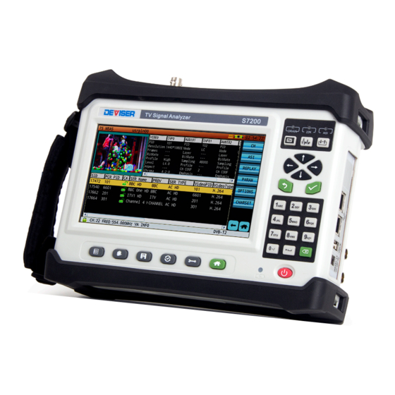
AD INSTRUMENTS S7200 TV Signal Analyzer Operation Manual Instrument Basic Information Introduction 4.1. Instrument Introduction 4.1.1. Front Panel Figure 4-1 Picture: S7200 Front Panel 7 inch color LCD, resolution: 800×480 Indicator light ① Battery charging indicator light Front panel buttons ②... - Page 35 AD INSTRUMENTS S7200 TV Signal Analyzer Operation Manual : Transport stream analysis shortcut key; : Spectrum analysis function shortcut key; : All signals input and output or signals transport path control. ④ Input and output signals’ indicator. DRAIN ⑤Main function button : Channel plan function shortcut key, to enter the channel plan, channel information and editing screens.
-
Page 36: Top Panel
AD INSTRUMENTS S7200 TV Signal Analyzer Operation Manual 4.1.2. Top Panel Figure 4-2 Picture: S7200 Top Panel Attention: RF input: DC~100Hz, max.: 30VDC, 5MHz~2150MHz, max.: +70dBmV。 Figure 4-3 Picture: S7200 Back Side... -
Page 37: Power Supply
(B) Right Side Figure 4-4 Picture: S7200 Left Side and Right Side 4.1.3. Power Supply There are 3 powering methods for the S7200, battery power, DC power adaptor or AC power adaptor. Battery The S7200 uses a 7.4V/13Ah lithium batteries for power. The autonomy is estimated at more than 8 hours, in measurement modes, when fully charged. - Page 38 AD INSTRUMENTS S7200 TV Signal Analyzer Operation Manual and again pop up the dialog box, indicating low battery status, at which time, the instrument will provide a long audible beep, and shut down automatically after that. The unit can then only operate if connected to an external AC or DC power source.
- Page 39 AD INSTRUMENTS S7200 TV Signal Analyzer Operation Manual When the charging indicator changes to green, the battery is full. It is suggested to keep charging for one hour more which will helps extend the usefuling time of the battery. After charging, unplug the DC connector, and then pull out the AC adaptor from the AC wall outlet.
-
Page 40: Button Introduction
AD INSTRUMENTS S7200 TV Signal Analyzer Operation Manual 4.1.4. Button introduction Battery charging indicator light. The indicator light status: The indicator light status: green means fully charged, red means charging in progress, and red and green flickering indicates no battery or battery abnormal. - Page 41 AD INSTRUMENTS S7200 TV Signal Analyzer Operation Manual Character and number buttons: each button includes 2 to 4 characters. Press once to input the first character, press twice to input the second character, three times to input the third character, and four times to input the fourth character or number.
- Page 42 AD INSTRUMENTS S7200 TV Signal Analyzer Operation Manual type frequency step in spectrum mode. Blue means this soft button status is unactive. Orange means this soft button status is active. The gray means this soft button status is not available.
-
Page 43: Touch Screen Operation Instruction
S7200 TV Signal Analyzer Operation Manual 4.1.5. Touch screen operation instruction S7200 uses the capacitive touch screen. Before many operation must use the button to do, now we can directly use finger on the capacitive touch screen to operate. So many operation steps become very simple, the follow contents will introduction the main touch screen operation. - Page 44 We often do input letter and number operation. We can use S7200 hard keyboard and soft keyboard. If user tap the input box, the soft keyboard will popup. S7200 provide two types soft keyboard according the input box requirement. The soft keyboard can provide more symbols than hard keyboard.
- Page 45 AD INSTRUMENTS S7200 TV Signal Analyzer Operation Manual multitouch operation. Move marker: User only need put the finger on one marker, then swipe the finger to the left or right. The marker will follow the finger move to different position, till user’s finger stop on one position.
- Page 46 AD INSTRUMENTS S7200 TV Signal Analyzer Operation Manual Figure 4-9 Decrease the span frequency range with both hands Figure 4-10 Decrease the span frequency range with one hand Figure 4-11 Increase the span frequency range with both hands...
- Page 47 AD INSTRUMENTS S7200 TV Signal Analyzer Operation Manual Modify center frequency: User need put the finger on the blank spectrum analysis measurement zone and swipe the finger to left or right side, the center frequency will change, as show in Figure 4-12.
-
Page 48: Main Menu Software Function
AD INSTRUMENTS S7200 TV Signal Analyzer Operation Manual 4.2. Main Menu Software Function 4.2.1. Main Menu Figure 4-14 Snapshot: Main Menu 4.2.2. Title Bar Figure 4-15 Title Bar The instruction of different devices and service icon in the title bar: : The instrument has recognized a USB disk. - Page 49 AD INSTRUMENTS S7200 TV Signal Analyzer Operation Manual : 22KHz signal status icon. When user uses the DisEqC protocol, this signal need open. : CA(Condition Access) card icon. Icon means CA module successful recognition, icon means the smart card successful recognition. The related programs can be decoded.
-
Page 50: Function Icon
AD INSTRUMENTS S7200 TV Signal Analyzer Operation Manual 4.2.3. Function Icon Measurement Scan Spectrum CSO/CTB Tilt Passive Sweep Measurement Spectrum Dish 4.2.4. Status Bar On the Home screen, the status bar will display which measurement mode you have chosen based on your selection. When you enter individual measurement... -
Page 51: Instrument Settings
AD INSTRUMENTS S7200 TV Signal Analyzer Operation Manual Instrument Settings 5.1. Brief Introduction Press to enter the setup interface The system setup screen offers 3 selections, - System information, - General settings - Measurement settings. 5.2. System Information Press > [About] will display such information as: Hardware and Software version, as shown below. -
Page 52: General Settings
AD INSTRUMENTS S7200 TV Signal Analyzer Operation Manual The second page displays information of the loaded options on your unit. Items with check marks confirm the options that have been installed on your device. Figure 5-2 Snapshot: System information-Options 5.3. General Settings... -
Page 53: Network Setting
WiFi icon in the title bar beside the battery icon reminding you that WiFi connection is active. - If both the WiFi box and DHCP box are checked, the S7200 will connect to the WiFi network automatically. - Page 54 S7200 TV Signal Analyzer Operation Manual Figure 5-5 Network Configuration-DHCP How to set your S7200 with an Ethernet connection; with DHCP or a static IP address, - In the network setup page, when the WiFi box is un-checked, the WiFi connection is inactive, the default connection is through the Ethernet connector, and the WiFi icon in the title bar is off.
- Page 55 An engineer can use this App to allow the S7200 onto a public network when he works in the field. If no good network connectivity is present, the field engineer can use this function to complete the measurement task and upload measurement results.
- Page 56 Figure 5-7 Setup S7200 as a WiFi hotspot Figure 5-8 WiFi AP SSID and password Setup When S7200 as a WiFi hotspot, the WiFi icon color is blue, Figure 5-9 show the WiFI icons difference. Figure 5-9 WiFi Icon-S7200 as a WiFi Hotspot...
-
Page 57: Ping
AD INSTRUMENTS S7200 TV Signal Analyzer Operation Manual 5.3.2. Ping PING is practical to quickly verify your network connectivity status and speed as shown in Figure 5-10 below. Figure 5-10 Ping Result Display Input the network address or the desired IP address to be tested in the host address box at the top (for example: www.bing.com), then press the [START]... -
Page 58: Display & Power
AD INSTRUMENTS S7200 TV Signal Analyzer Operation Manual 5.3.3. Display & Power From the general settings page, tap the display & battery option. Users can set the shutdown time-lapse and backlight time-lapse. The internal temperature of the instrument is displayed, both in Farenheit and Celsius. -
Page 59: Date & Time
AD INSTRUMENTS S7200 TV Signal Analyzer Operation Manual 5.3.4. Date & Time Upon initial activation of the unit, the system date & time needs to be set. Figure 5-12 Snapshot: Data & Time Setting There are three ways of displaying the date, YYYY/MM/DD, DD/MM/YYYY and MM/DD/YYYY. - Page 60 AD INSTRUMENTS S7200 TV Signal Analyzer Operation Manual Figure 5-13 Division of the world's 24 time zones Standard time in the world is GMT (Greenwich Mean Time) plus (+) or minus (-) the number of time zones in the subject of the hour time difference. Instruments need to set the time zone corresponding to the location selection, location and time zone relationship such as shown in Figure 5-13.
-
Page 61: Language
AD INSTRUMENTS S7200 TV Signal Analyzer Operation Manual 5.3.5. Language The S7200 supports multiple languages, only Chinese, English and Russian are currently supported. To switch between languages, tap the language setting item. Tap on you needed language option. Once your selection is made, a pop up window will indicate “the system needs to restart for the changes to take effect”... -
Page 62: User Management
Press the [LOGIN] soft button to enter the S7200 home page. When you choose different users, all users are independent from one another, however, channel lists and limit files are shared and can be selected by any or all users. - Page 63 AD INSTRUMENTS S7200 TV Signal Analyzer Operation Manual Figure 5-16 Snapshot: Multi-User Function Edition In Figure 5-15, user can modify the current login user information. User can edit user name (USER1), user ID (0000000001), company name (GROUP). When the user chooses other user's ID, he can not modify other user information in this account.
-
Page 64: Gps
GPS antenna integrate in one module. GPS module use USB cable connect with S7200. If S7200 not install GPS module, user also can manually input GPS information and user can save the manually input GPS information in test results, as the Figure 5-18 show. - Page 65 AD INSTRUMENTS S7200 TV Signal Analyzer Operation Manual save test results, user local position latitude and longtitude information can be saved in test result information, as the Figure 5-20 show. Figure 5-19 GPS Location Successful Figure 5-20 The GPS Information Saved in Test Result...
-
Page 66: Disk Management
AD INSTRUMENTS S7200 TV Signal Analyzer Operation Manual 5.3.8. Disk Management Disk management function is used to check SATA SSD option or U disk information. When user’s instrument install SATA SSD option, the interface will display a “Format” button, as the Figure 5-21 shows. If user’s instrument no SATA SSD option, user can not find “Format”... -
Page 67: Restoring Factory Settings
This feature restores all configuration parameters (only) to the original factory settings, however, all saved files in S7200 remain intact, as saved, for each of the users. After a factory reset, if multiple-users are active, the S7200 will revert to the first user on the list by default. -
Page 68: Available Option
To activate your options, if they haven’t yet been activated following your initial purchase, you need to enter the options list screen on your S7200. To enter this menu, on the numerical keypad, you need to press 1, 2, 3, 4, 5, 6 one after the other. -
Page 69: S7200 System Upgrade Operation Steps
July 11, 2015 and 9 o'clock 14 minutes and 25 seconds. The program uses this time stamp to confirm which firmware is the latest version. Upgrade instructions: With the instrument powered OFF, insert the USB-disk into the S7200 USB port, then press and hold the button, simultaneously press down on the power on button, until the instrument powers up and enters the upgrade function interface screen. - Page 70 AD INSTRUMENTS S7200 TV Signal Analyzer Operation Manual you can release the and power buttons. The user can then choose the upgrade option [in this case, upgrade from USB], and enter the user upgrade mode. Figure 5-26 Snapshot: Choose Program Upgrade mode...
- Page 71 AD INSTRUMENTS S7200 TV Signal Analyzer Operation Manual Figure 5-28 Snapshot: Program Upgrade - Update Program [Format Data Memory] This function will only format apps and data partitions, this will not influence other partitions. If the user does not have any special requirements, this function is not typically used.
-
Page 72: Measurement Settings
5.4.1. Level Unit There are different units of measure for different countries and industries, the S7200 supports 3 unit formats: dBmV, dBμV and dBm and will automatically convert values for convenience and better user experience. Figure 5-29 Snapshot: Level Unit Settings... -
Page 73: Test Point Compensation
AD INSTRUMENTS S7200 TV Signal Analyzer Operation Manual 5.4.2. Test Point Compensation Tap the “TP Compensation” item, continue tap the checkbox in the middle window. TP compensation can be edited and applied only if the box is checked. Figure 5-30 Snapshot: Test point compensation screen... - Page 74 AD INSTRUMENTS S7200 TV Signal Analyzer Operation Manual Figure 5-31 Example of Test Point Compensation Figure 5-32 Screen location of TP Compensation in the Measurement Screen...
-
Page 75: Adaptive Equalizer
AD INSTRUMENTS S7200 TV Signal Analyzer Operation Manual 5.4.3. Adaptive Equalizer The S7200 offers adaptive equalizer setup : The adaptive equalizer setup only for Cable TV take effect. Long Taps and Short Taps. Long Taps can better suppression (Inter Symbol... - Page 76 AD INSTRUMENTS S7200 TV Signal Analyzer Operation Manual Equalizer setup in measurement screen position. Figure 5-35 Equalizer Setup: Long Tap Measurement Figure 5-36 Equalizer Setup: Short Tap Measurement...
-
Page 77: Transport Stream Setting
AD INSTRUMENTS S7200 TV Signal Analyzer Operation Manual 5.4.4. Transport Stream Setting The TS analysis function supports DVB and ATSC standard. For different country or district, user self choose DVB or ATSC according local standart. DVB option display PSI/SI analysis and ATSC option display PSI/PSIP analysis. Figure 5-38 shows the content. - Page 78 AD INSTRUMENTS S7200 TV Signal Analyzer Operation Manual Figure 5-39 Transport Stream Parameters Setup Option Data format has two options: Decimalism and hexadecimal. Figure 5-40 shows Decimalism PID value is 850 and hexadecimal PID value is 0x352. Figure 5-40 Decimal and hexadecimal PID Value Contrast...
- Page 79 AD INSTRUMENTS S7200 TV Signal Analyzer Operation Manual Closed captions: Only ATSC standard uses the closed captions. Close the closed captions, no captions display on the screen. Open the closed captions, the captions display on the screen again. The closed captions effect as show in the Figure 5-41.
- Page 80 AD INSTRUMENTS S7200 TV Signal Analyzer Operation Manual Figure 5-42 Character Encoding Option List S7200 supports the fellow Character Encoding Options: Auto Detects Romanian (ISO 8859-16) West European (ISO 8859-15) Celtic (ISO 8859-14) Baltic (ISO 8859-13) Thai (ISO 8859-11) North European (ISO 8859-10) West European &...
-
Page 81: Transport Stream Limit Setting
AD INSTRUMENTS S7200 TV Signal Analyzer Operation Manual 5.4.5. Transport Stream Limit Setting TR 101 290 Priority 1, 2 and 3 tests parameters limit value can be modified and applied in the realtime transport stream analysis. Figure 5-43 TR 101 290 Priority 1, 2 and 3 Tests Parameters Limit The table give some parameters reference value. -
Page 82: Create And Edit A Channel Plan
The S7200 features an automatic channel plan builder; it will identify peak levels and frequency of analog carriers available as well as identify digital carriers. - Page 83 AD INSTRUMENTS S7200 TV Signal Analyzer Operation Manual Figure 5-44 Snapshot: Edit Channel Plan-Choose Channel Plan All channels are listed in the middle window. [ENA ALL] / [DIS ALL] for fast edit of channel status. If only a few select channel need to change active status, hit the edit softkey, the appropriate softkey menu will popup.
- Page 84 The S7200 features an automatic channel plan builder; it will identify peak levels and frequency of analog carriers available as well as identify digital carriers.
-
Page 85: Export A Channel Plan
S7200 TV Signal Analyzer Operation Manual 5.5.2. Export a Channel Plan Users can insert a USB Disk in the S7200 USB port, the export channel plan softkey will then become active. Tap the soft button [EXPORT], the screen will pop up a EXPORT window, user can choose need exported channel plan from the channel plan list. - Page 86 AD INSTRUMENTS S7200 TV Signal Analyzer Operation Manual Similar operation steps can apply on import channel plan, as show in Figure 5-49. This function can be used to clone channel plan on different units. Figure 5-49 Import Channel Plan...
-
Page 87: Edit Channel
AD INSTRUMENTS S7200 TV Signal Analyzer Operation Manual 5.5.3. Edit Channel In channel plan screen, tap the [EDIT] button can open the channel edit screen. Cable and terrestrial broadcast channel type include: ANALOG FM, ANALOG TV, DVB-C, DOCSIS, DVB-T/H, DVB-T2, ATSC. - Page 88 AD INSTRUMENTS S7200 TV Signal Analyzer Operation Manual user want to quit this page, you must press the [SAVE] button, otherwise the change can’t be saved. Figure 5-52 Edit ANALOG FM channel parameters Analog FM channel parameters: Channel serial number: channel use number name display...
- Page 89 AD INSTRUMENTS S7200 TV Signal Analyzer Operation Manual Figure 5-53 Edit Analog TV Channel Parameters Analog TV channel parameters: Channel serial number: channel use number name display Channel name: no option, editable content Channel status: ENABLE、DISABLE Signal type: ANALOG TV...
- Page 90 AD INSTRUMENTS S7200 TV Signal Analyzer Operation Manual CTBCSO mode: GATE OFF, GATE ON CTBCSO field: ODD, EVEN CTBCSO line: 525 lines system: Field 1 (odd), line 1~263; Field 2 (even), line 2~262 625 lines system: Field 1 (odd), line 1~313; Field 2 (even),...
- Page 91 AD INSTRUMENTS S7200 TV Signal Analyzer Operation Manual Figure 5-54 Edit Digital TV Channel Parameters Digital channel parameters option: Channel serial number: channel use number name display Channel name: no option, editable content Channel status: ENABLE、DISABLE Signal type: DVB-C System rate:...
- Page 92 AD INSTRUMENTS S7200 TV Signal Analyzer Operation Manual US and EU Default Symbol Rate for DVB-C: Standard and Modulation Type Symbol Rate Bandwidth ITU-T J.83 Annex A 64QAM 6.952MS/s 8MHz ITU-T J.83 Annex A 256QAM 6.952MS/s 8MHz ITU-T J.83 Annex B 64QAM 5.057MS/s...
- Page 93 AD INSTRUMENTS S7200 TV Signal Analyzer Operation Manual Frequency: editable content Measure BW: editable content STD: DOCSIS、EuroDOCSIS Modulation: 64QAM、256QAM SR (System Rate): The symbol rate is auto-configured according to the modulation type and standard. It will set automatically once the modulation type and standard are selected.
- Page 94 AD INSTRUMENTS S7200 TV Signal Analyzer Operation Manual Figure 5-56 Edit DVB-T/H Channel Parameters DVB-T/H channel parameters option: Channel serial number: channel use number name display Channel name: no option, editable content Channel status: ENABLE、DISABLE Signal type: DVB-T/H System rate:...
- Page 95 AD INSTRUMENTS S7200 TV Signal Analyzer Operation Manual Figure 5-57 Edit DVB-T2 Channel Parameters DVB-T2 channel parameters option: Channel serial number: channel use number name display Channel name: no option, editable content Channel status: ENABLE、DISABLE Signal type: DVB-T2 System rate:...
- Page 96 The user must choose OK to save changes or choose CANCEL to quit this function without saving. More channel plan templates are available in the S7200 Toolbox software. Our company may be able to write customer specific channel plans upon request.
-
Page 97: Create And Edit Satellite Channel Plan
AD INSTRUMENTS S7200 TV Signal Analyzer Operation Manual 5.5.4. Create and Edit Satellite Channel Plan When system switch to satellite mode, press the button, S7200 will open satellite channel plan edit interface. Left side colume is satellite list (include satellite name and satellite longitude). The asterisk (*) identifies to the active satellite. - Page 98 AD INSTRUMENTS S7200 TV Signal Analyzer Operation Manual The following content will provide some create satellite channel plan related basic knowledge. Broadcast satellite is the geostationary orbit satellite. Each satellite in geosynchronous orbit over the equator on a fixed position point, its purpose is to make every broadcast satellite to be able to cover the designated service area.
- Page 99 AD INSTRUMENTS S7200 TV Signal Analyzer Operation Manual Figure 5-61 Sub-satellite point Often used satellite broadcast frequency band is C band (3.4 ~ 4.2GHz) and Ku band (10.7 ~ 12.75GHz).
- Page 100 AD INSTRUMENTS S7200 TV Signal Analyzer Operation Manual C band satellite transponder frequency allocation table Transponder Number polarization Downlink freqnency (MHz) Bandwidth range (MHz) 3720 3702~3738 3740 3722~3758 3760 3742~3778 3780 3762~3798 3800 3782~3818 3820 3802~3838 3840 3822~3858 3860 3842~3878...
- Page 101 AD INSTRUMENTS S7200 TV Signal Analyzer Operation Manual Ku band satellite channel allocation Channel Downlink Channel Downlink Channel Downlink frequency frequench frequency (MHz) (MHz) (MHz) 11727.48 11880.92 12034.36 11746.66 11900.10 12053.54 11765.84 11919.28 12072.72 11785.02 11938.46 12091.90 11804.20 11957.64 12111.02 11823.38...
- Page 102 AD INSTRUMENTS S7200 TV Signal Analyzer Operation Manual user fill content; the band provide two options: DL-C and DL-Ku. After user complete all parameters setup, tap the [ADD] button below the parameters, the program will open satellite transponder list interface, as the Figure 5-63 show.
- Page 103 AD INSTRUMENTS S7200 TV Signal Analyzer Operation Manual Satellite transponder parameter Satellite longitude: Come from satellite parameter Low oscillator: User fill content High oscillator: User fill content Transponder name: User fill content Transponder status: Enable, Disable Channel type: ANALOG TV, DVB-S, DVB-S2, DSS...
- Page 104 AD INSTRUMENTS S7200 TV Signal Analyzer Operation Manual 950~2150MHz Mixer IF Amplifier Figure 5-65 LNA Block Diagram Satellite signals have two types polarization: circular polarization and linear polarization. The circular polarization include right-hand circular and left-hand circular polarizations. The linear polarization include horizontal and vertical polarizations.
- Page 105 AD INSTRUMENTS S7200 TV Signal Analyzer Operation Manual About LNB local oscillator C band LNB single local oscillator use 5150MHz and 5750MHz. IRD receives signal frequency range is 950~2150MHz, and C band full bandwidth about 500MHz, only about half of the 950~2150MHz. Some new products provide two sets of circuits to respectively handle horizontal polarization and vertical polarization signals.
- Page 106 AD INSTRUMENTS S7200 TV Signal Analyzer Operation Manual Some manufactures provide double local oscillator Ku band LNB, it provide two sets of circuits and local oscillator for different polarization, often used LO are 9.75GHz and 10.6GHz. User can use 0/22kHz impulse signal to control low frequency band LO and high frequency band LO work.
-
Page 107: External Interface Setup
AD INSTRUMENTS S7200 TV Signal Analyzer Operation Manual 5.6. External Interface Setup In TV and satellite mode, the external interface setup has different parameters option. In TV mode, include: LNB Power, Optical/RF, TS Input/ASI Output. In satellite mode, include: LNB Power, DiSEqC, SaTCR, Optical/RF, TS Input/ASI Output. - Page 108 AD INSTRUMENTS S7200 TV Signal Analyzer Operation Manual Figure 5-68 Satellite Mode Power Setup When user have multi satellite receive or multi user receiver requirement, the control signals 13/18V, 0 / 22kHz and DiSEqC are needed. We know, 18V is used to control horizontal polarization, 13V is used to control vertical polarization.
- Page 109 AD INSTRUMENTS S7200 TV Signal Analyzer Operation Manual the frequency is 0kHz, as the Figure 5-69(E) show. If user want to receive Ku band low band vertical polarization signal, the 22kHz square-wave signal is not superimposed on 13V signal, the 0/22kHz status is “Off”, the frequency is 0kHz, as the Figure 5-69(F) show.
-
Page 110: Diseqc Control Signal
DiSEqC has been developed several versions, every version use DiSEqC icon + version to describe. Every new version has backword compatibility. S7200 support 1.0, 1.1, 1.2, 2.x version DiSEqC protocol. If LNB power supply status is disable, when user sent DiSEqC command to LNB, the screen will tips “Please enable the LNB power supply!”. - Page 111 AD INSTRUMENTS S7200 TV Signal Analyzer Operation Manual Version Provide basic DiSEqC instruction set, has Tone Burst function and four LNB control. It can use a series of instructions to send these commands: polarization, high and low bands, DiSEqC1.0 antenna position and other control. But it was a unidirectional system, the receiver send instruction to the system corresponding module.
- Page 112 AD INSTRUMENTS S7200 TV Signal Analyzer Operation Manual RESET ---- General STANDBY ---- POWER ON ---- SAT A/B POSITION A/B OPTION A/B Switch control OPT/POS A-A/A-B/B-A/B-B DiSEqC1.0 SWITCH 1 to 4 DiSEqC1.1 SWITCH 1 to 16 HALT ---- DISABLE LIMITS...
-
Page 113: Satcr Control Signal
Figure 5-72 show. Figure 5-72 SaTCR Control Signal Configure Interface SaTCR protocol control command transmission need S7200 power supply status enable. When power supply off or other external device power supply, this function doesn’t take effect. - Page 114 AD INSTRUMENTS S7200 TV Signal Analyzer Operation Manual S7200 max support 8 slots SaTCR LNB。 Command Parameter Description SaTCR status Enable/Disable Enable/Disable the SaTCR Funciton NUM of SLOTS 2 / 4 / 8 Num of SaTCR LNB Slots SELECT SLOT...
- Page 115 AD INSTRUMENTS S7200 TV Signal Analyzer Operation Manual SaTCR principle introduction Legacy output (Option) SaTCR-1 950MHz 2150MHz 4×2 ∑ 1210MHz 1420MHz Probe Unicable 4×3 Output Matrix Choke SaTCR-1 Unicable ST7LNB1 One Cable Figure 5-73 Unicable LNB Block Diagram Unicable LNB receive Ku band satellite signal similar with traditional LNB, the difference is add SCR and MCU chip.
- Page 116 AD INSTRUMENTS S7200 TV Signal Analyzer Operation Manual corresponding to the desired transponder. The polarization is selected by changing the voltage of the LNB supply (13 volts for vertical polarization, 18V for horizontal polarization). The local oscillator is selected by adding or not a 22kHz tone on the LNB supply (when 22kHz in on the highest LO is selected).
-
Page 117: Asi Input And Output Control
AD INSTRUMENTS S7200 TV Signal Analyzer Operation Manual 5.6.4. ASI Input and Output Control ASI input and output port on the right side of the instrument. Choose the ASI input status valid, the icon display on the title bar. ASI input and output introduction as the Figure 5-74 and Figure 5-75 show. -
Page 118: Transport Stream Input Control
S7200 TV Signal Analyzer Operation Manual 5.6.5. Transport Stream Input Control S7200 has four types transport stream input types: RF, ASI, DISK, IPTV. RF input : The cable, terrestrial and satellite signal from the RF input port enter instrument. The transport stream is demodulated from the RF signal, then enter TS analysis module. - Page 119 AD INSTRUMENTS S7200 TV Signal Analyzer Operation Manual Figure 5-78 RF Input Parameters Setup ASI input: The ASI input port on the right side of the instrument. The baseband transport stream signal from the ASI input port enter the TS analysis module. The Figure 5-79 shows setup interface.
- Page 120 AD INSTRUMENTS S7200 TV Signal Analyzer Operation Manual Figure 5-80 ASI Input Transport Stream does TS Analysis DISK input: This option change the internal SATA SSD (Solid State Disk) or USB disk as the transport stream source. When the title bar display the icon...
- Page 121 AD INSTRUMENTS S7200 TV Signal Analyzer Operation Manual Figure 5-82 Choose TS file form SATA SSD or USB Disk Figure 5-83 Disk Input Transport Stream does TS Analysis IPTV input: This option can change the TS input source switch to IPTV signal come from network.
- Page 122 AD INSTRUMENTS S7200 TV Signal Analyzer Operation Manual Figure 5-84 Transport Stream Input Control – IPTV Figure 5-85 IPTV Analysis IPTV Signal Figure 5-86 IPTV Input Transport Stream does TS Analysis...
-
Page 123: Reviewing & Exporting Files
AD INSTRUMENTS S7200 TV Signal Analyzer Operation Manual 5.7. Reviewing & Exporting Files 5.7.1. File management Tap the button on the front panel below the screen to open the file management menu. The saved files are available in 3 different categories, picture, data and TS. - Page 124 AD INSTRUMENTS S7200 TV Signal Analyzer Operation Manual one or more files are chosen, and a USB storage disk is inserted, the export button becomes active. Figure 5-88 Screenshot Delete file Figure 5-89 Screenshot Export file (USB stick inserted)
- Page 125 AD INSTRUMENTS S7200 TV Signal Analyzer Operation Manual Figure 5-90 Screenshot Data File Operation Figure 5-91 Transport Stream File List...
-
Page 126: Reviewing Files
AD INSTRUMENTS S7200 TV Signal Analyzer Operation Manual 5.7.2. Reviewing Files Picture files can be viewed in this menu. Data files show different information based on type, but all will include the basic information of the instrument; system, software/firmware version, machine type, serial number, calibration time, operator name, operator ID, company name, date &... -
Page 127: File Saving
AD INSTRUMENTS S7200 TV Signal Analyzer Operation Manual 5.8. File Saving Tap the button to store screen snapshots and test results. If you tap the button in a non-measurement screen, the instrument will ask “Please enter the file name” and offer a suggested file name. This is your opportunity to enter a custom file name, if you just press “enter”, the file name... - Page 128 AD INSTRUMENTS S7200 TV Signal Analyzer Operation Manual Figure 5-95 Snapshot: Picture Add Watermark Option Figure 5-96 Snapshot: Watermark Display Effect...
-
Page 129: Measurement Function
6.1. Analog TV Measurement 6.1.1. Channel Measurement In this mode, the S7200 measures the basic parameters of a channel. The channel types currently supported all TV standard. For different channel types, the channel measurement screen offers different settings and measurement parameters. - Page 130 AD INSTRUMENTS S7200 TV Signal Analyzer Operation Manual Figure 6-1 Snapshot: Channel Measurement - Analog TV Analysis Parameter Instruction Channel, can select between all active channels in the active channel plan. Video Frequency input range: 5MHz-1200MHz; Audio Frequency input range: 5MHz-1200MHz;...
-
Page 131: Analog Fm
AD INSTRUMENTS S7200 TV Signal Analyzer Operation Manual 6.1.2. Analog FM The Analog FM measurement screen, shown below, is primarily used to measure level. If user tap the soft button [LISTEN], the listen FM function work and modify volume button also is actived. -
Page 132: Hum Modulation
The low frequency interference and interference harmonic will disrupt the analog TV signal, the hightest measurable fourth harmonic of the S7200 are : - 50Hz, 100Hz, 150Hz and 200Hz in 50Hz, - 60Hz, 120Hz, 180Hz and 240Hz in 60Hz. -
Page 133: Channel Scan
S7200 TV Signal Analyzer Operation Manual 6.1.4. Channel Scan The S7200 offers a channel scan function to quickly measure the flatness and amplitude of a CATV system. The interface is shown in Figure 6-5 below. By default, the device will scan all active channels in an active channel plan. Video and audio carrier levels will appear at the same bar graph position with a different color, one superimposed over the other. - Page 134 AD INSTRUMENTS S7200 TV Signal Analyzer Operation Manual Figure 6-5 Channel SCAN Frequency SCAN provide a marker, user can use finger directly operation this marker on touch screen. Move marker: User only need put the finger on one marker, then swipe the finger to the left or right.
-
Page 135: Passive Sweep
S7200 initiate a channel sweep measurement at the optical receiver test port, and store the trace measurement result as reference trace. Then connect the S7200 at the RF output port of optical reciever, and initiate a second channel sweep measurement. Compare the measurement signal with the saved signal. We could see that the differential value is 19.6dB, which indicates that the signal... - Page 136 AD INSTRUMENTS S7200 TV Signal Analyzer Operation Manual and signal fluctuation. If the user active the test point compensation function, the saved reference trace value also include compensation value. The passive sweep function display compensation value at the lower left corner of the screen, display applied reference value at the lower right corner of the screen.
-
Page 137: Tilt Measurement
AD INSTRUMENTS S7200 TV Signal Analyzer Operation Manual 6.1.6. Tilt Measurement To quickly measure the flatness of a CATV system and the gain of the splitters/taps, select the tilt measurement. This feature measures quickly the level and power of up to 16 channels. - Page 138 AD INSTRUMENTS S7200 TV Signal Analyzer Operation Manual Figure 6-10 Tilt Measurement – Channel Listing Display The below Figure 6-11 is the tilt editing page. Choose 4-16 channels among all active channels in the active channel plan to perform a tilt measurement. All active channels in the channel plan are listed and available in the edit tilt plan page.
- Page 139 AD INSTRUMENTS S7200 TV Signal Analyzer Operation Manual Measurement Results Low frequency channels are displayed at the left, high frequency channels are displayed at the right of the graph. No matter what your channel selection is, they will all be placed in order automatically. Tilt results are measured between Marker A &...
-
Page 140: Analog Non-Linear Distortion Measurement
6.2. Analog Non-linear distortion measurement 6.2.1. Carrier to Composite Noise Ratio Measurement To measure CCN Ratio with your S7200, you must set-up the video carrier frequency and noise bandwidth correction correctly in the channel plan editor. Noise bandwidth is different depending on the channel bandwidth, which depends on your location. - Page 141 12), if you choose a higher VITS line, you may start encountering video modulation, thus visible interference on the television picture… In the gated mode, the S7200 will first measure peak carrier level, then will trigger on the appropriate VITS line # (preset for each channel to be set in the channel plan editor) to measure system noise.
- Page 142 AD INSTRUMENTS S7200 TV Signal Analyzer Operation Manual (setup in the channel plan editor) CCN gated measurement support the fellow TV standard System and Standard Line/Frame Field Color encoding frequency technique NTSC-M 60Hz NTSC PAL-M 60Hz NTSC PAL-B、D、G、H、I、K 50Hz PAL-N 50Hz Per frame 525 lines system: Field 1 (odd field), line 1-263;...
-
Page 143: Cso And Ctb Measurement
When we measure CSO and CTB, the test results are C/CSO and C/CTB, C meaning carrier level. In the gated mode, the S7200 will first measure absolute carrier level, then will trigger on the appropriate VITS line # to measure system noise. (preset... - Page 144 A quiet line is absolutely required when one needs to measure CCN, CSO, CTB, or cross-modulation. The S7200 offers triggering technology that accurately locks on a specific VITS line and provide very accurate measurement results.
- Page 145 AD INSTRUMENTS S7200 TV Signal Analyzer Operation Manual Figure 6-17 Gated CSO/CTB Measurement – Time Domain Waveform...
-
Page 146: Analog Tv Video Parameters Measurement
AD INSTRUMENTS S7200 TV Signal Analyzer Operation Manual 6.3. Analog TV Video Parameters Measurement Analog TV video measurements required by the FCC include: Depth of Modulation. If you want to make those measurements in the gated mode, you must use a VITS inserter to insert the various test signals needed for specific measurements. -
Page 147: Depth Of Modulation
AD INSTRUMENTS S7200 TV Signal Analyzer Operation Manual 6.3.1. Depth of Modulation In analog TV measurement mode, tap the soft button [DOM] to enter Depth of Modulation menu. Depth of modulation is measured as the percentage of the total amplitude change of the carrier, as the signal progresses from sync tip to peak white. -
Page 148: Digital Signal Measurement
- EVS (Error vector spectrum), - Digital channel CNR - Digital Hum. Parameter Settings Adjustable parameters and range of the DVB-C function of the S7200 are listed below: CH-Channel NO.: ——Value Range: all active channels or active digital channels in the active... -
Page 149: Dvb-C Measurement
AD INSTRUMENTS S7200 TV Signal Analyzer Operation Manual 6.4.1. DVB-C Measurement The digital channel measurement screen shown below in Figure 6-19, displays the basic digital metrics after demodulation. Figure 6-19 Channel Measurement – QAM Signal Analysis User can use finger directly tap parameter’s position use virtual keyboard enter content or from drop list to choose one item. -
Page 150: Digital Hum
Hum modulation is also called power source frequency modulation distortion and comes from a power source frequency interference. HUM modulation generally degrades MER values of a digital carrier. The S7200 supports hum modulation measurements for digital channels. The measurement interface is shown below in Figure 6-20. - Page 151 AD INSTRUMENTS S7200 TV Signal Analyzer Operation Manual Softkey button description: [50Hz] / [60Hz] press this button to switch the power frequency between 50Hz or 60Hz. [Hold] press this button to pause, and press again to continue to refresh the interface You can choose the AC power frequency according to your local region.
-
Page 152: Constellation Diagram
AD INSTRUMENTS S7200 TV Signal Analyzer Operation Manual 6.4.3. Constellation Diagram The DVB-C constellation diagram function is shown below in Figure 6-21. Figure 6-21 Constellation display In power measurement function, tap the soft button [CONS>] to open the constellation diagram interface. You can refresh and zoom the constellation. The diagram zoom-in function will only zoom one of the four quadrant of the diagram. - Page 153 AD INSTRUMENTS S7200 TV Signal Analyzer Operation Manual Figure 6-23 Constellation Zoom – Zoom In & Zoom Out User can use tap the parameter on touch screen to modify parameter value or use arrow key to modify parameters value, or or input the value with the numerical keypad.
-
Page 154: Error Vector Spectrum (Evs) Function
AD INSTRUMENTS S7200 TV Signal Analyzer Operation Manual 6.4.4. Error Vector Spectrum (EVS) Function The EVS function is a great tool to help find signal interference under the QAM (DV or DOCSIS), but the greatest benefit is that the test can be performed in- service. - Page 155 These types of bandwidth are all close or wider than DVB-C signal bandwidth. Both LTE signals and DVB-C signals are digital signals, all of them are similar with noise. The S7200 uses the EVS time domain function to measure the LTE interference results, shown as the below Figure 6-25.
-
Page 156: Atsc (8Vsb) Measurement
(high) side of the spectrum. Center frequency : the carrier center frequency Modulation type : 8VSB Symbol rate : 10.762MS/s If all parameters was setup right and the signal no problem, the S7200 can correctly demodulate 8VSB signal. Figure 6-26 8VSB Average Power Measurement... - Page 157 AD INSTRUMENTS S7200 TV Signal Analyzer Operation Manual In average power measurement interface, the screen display 8VSB signal average power, MER, Pre-BER and Post-BER. The average power use the histogram display. 8VSB constellation diagram include 8 vertical lines. Every line is compoised by many constellation points.
- Page 158 AD INSTRUMENTS S7200 TV Signal Analyzer Operation Manual Figure 6-28 8VSB Diagram Figure 6-29 Decreased signal quality, eye diagram gradually closed In the US, the FCC has specified different emission masks for different types of 8- VSB DTV transmitters. One mask is specified for Full Service digital transmitters.
- Page 159 Figure 6-30 Simple Emissions Mask requirements for low power 8-VSB LPTV transmitters and translators S7200 only support 8-VSB Simple Emission Limits, as the Figure 6-30 show. The Figure 6-31 shows the 8-VSB spectrum mask test PASS status, the screen display a green text “PASS”, no alarm sound.
- Page 160 AD INSTRUMENTS S7200 TV Signal Analyzer Operation Manual So user can tap the soft button [ATT>] to open attenuator modify sub-menu. User taps the button [INPUT] can directly input attenuator value, tap the button [INC] or [DEC] to increase or decrease the attenuator value. By modify attenuator, some signal can meet the Simple Emissions Mask requirements.
- Page 161 AD INSTRUMENTS S7200 TV Signal Analyzer Operation Manual Figure 6-33 Spectrum Mask Test – List Display...
-
Page 162: Dvb-C2 Measurement
AD INSTRUMENTS S7200 TV Signal Analyzer Operation Manual 6.6. DVB-C2 measurement S7200 support DVB-C2 signal demodulation, include 1024QAM and 4096QAM signal. User can read L1 and SLICE ID information. Figure 6-34 DVB-C2 Power Measurement Figure 6-35 DVB-C2 4096QAM Constellation... - Page 163 AD INSTRUMENTS S7200 TV Signal Analyzer Operation Manual Figure 6-36 DVB-C2 1024QAM Constellation A DVB-C2 frame begins with preamble symbols which are repeated every 7.61MHz and have a width of 3408 carriers each. These are followed by the data symbols, a total 448 data symbols. The preamble symbols are used both for time and frequency synchronization and for signaling of the Layer-1 (L1) parameters.
-
Page 164: Dvb-T/H Measurement
First step need setup the channel type as DVB-T/H in channel plan edit function. Center Frequency editable content For all other parameters, the S7200 auto detect from the pilot and TPS carrier. (S7200 not support DVB-H 4k carriers mode) If all parameters was setup right and the signal no problem, the S7200 can correctly demodulate DVB-T/H signal. - Page 165 S7200 DVB-T/H constellation function has multi-type display: All carriers constellation, only one carrier constellation, hierachical modulation constellation. S7200 DVB-T/H function default display all carriers constellation, as the Figure 6-38 show. When user taps the soft button [CARRIER], parameter “CARRIER” can be edit in the parameters list.
- Page 166 AD INSTRUMENTS S7200 TV Signal Analyzer Operation Manual Figure 6-38 DVB-T/H All Carrier Constellation Figure 6-39 DVB-T/H Sub-Carrier Constellation - Data Figure 6-40 DVB-T/H Sub-Carrier Constellation - TPS...
- Page 167 AD INSTRUMENTS S7200 TV Signal Analyzer Operation Manual DVB-T 8k mode has 6817 sub-carriers and 2k mode has 1705 sub-carriers. All sub- carriers can be classified into three types: (1) Data carriers are used to transmit digital TV transport stream MPEG-2 signal.
- Page 168 AD INSTRUMENTS S7200 TV Signal Analyzer Operation Manual DVB-T introduce the hierarchical modulation conception, the adjacent quadrants symbol use nonuniform mapping. DVB-T define a parameter factor α, α=1, 2, 4. The factor α means the distance which a symbol is the closest to the axes X and Y.
- Page 169 AD INSTRUMENTS S7200 TV Signal Analyzer Operation Manual Post-echo scenario The transmission scenario and the channel impulse response for post-echos are show in Figure 6-43. In the post-echo scenario, the strongest path (main path) is from the nearest transmitter tower and the other paths are either from transmitters located further away or from reflections which arrive after the main path and have lower power levels.
- Page 170 AD INSTRUMENTS S7200 TV Signal Analyzer Operation Manual Figure 6-44 Pre-echo Scenario and the Associated Channel Impulse Response Pre-echoes and post echoes A pre-echo and post-echo scenario occurs when both a pre-echo and a post-echo exist in the transmission channel. The transmission scenario and channel impulse response are shown in Figure 6-45.
- Page 171 AD INSTRUMENTS S7200 TV Signal Analyzer Operation Manual The Figure 6-46 is echo pattern analysis interface. The main path signal at the center of the pattern. At the left side of the main path is pre-echo, at the right side of the main path is the post-echo. The area of not covered by the shadow is area of guard interval.
-
Page 172: Dvb-T2 Measurement
T2-Lite is specified in an updated version of the DVB-T2 standard – was published by ETSI in 2012 (EN 302 755 v.1.3). S7200 support EN 302 755 V1.1.1, V1.2.1 and V1.3.1 DVB-T2 signal test. S7200 provide the follow test functions: average power, MER, CBER, VBER and constellation test, echo patten, provide L1 and PLP information. - Page 173 AD INSTRUMENTS S7200 TV Signal Analyzer Operation Manual receiver. A TV receiver is able to identify and correct certain amounts of error in the transmission channel. In the TV receiver, error correction takes place in two distinct stages called Viterbi (or ‘outer’) and Reed Solomon (or ‘inner’) correction.
- Page 174 AD INSTRUMENTS S7200 TV Signal Analyzer Operation Manual a manner that the two components in the imaginary plane, in-phase I and quadrature Q, carry all the binary information. Then, the real and imaginary parts of each symbol are cyclically delayed and end up being transmitted in different subcarriers.
- Page 175 Figure 6-49 Mapping, rotation and Q delay Figure 6-50 Cyclic Q delay between adjacent cells The S7200 measures DVB-T2 rotated constellation shows in Figure 6-51. The constellation only for PLP content. If DVB-T2 signal only include one PLP, user can not change “PLP ID”...
- Page 176 T2 signals. The dynamic part signals the position of the PLPs in each frame and changes from frame to frame. The S7200 can provide signaling, the Figure 6-53 shows S7200 can provide all singlings information.
- Page 177 VCM – Variable Coding and Modulation. The S7200 provides DVB-T2 PLP information show in Figure 6-54. Figure 6-54 DVB-T2 Mode A PLP Information...
- Page 178 AD INSTRUMENTS S7200 TV Signal Analyzer Operation Manual The echo principle related content please reference DVB-T/H echo test part. Figure 5-53 shows S7000 does DVB-T2 echo test interface. Figure 6-55 DVB-T2 Echoes Measurement...
-
Page 179: Isdb-T Measurement
AD INSTRUMENTS S7200 TV Signal Analyzer Operation Manual 6.9. ISDB-T Measurement The ISDB system was designed for high-quality audio, video, and associated data. Originally, it was developed by and for Japan. In 2006, Brazil adopted a slightly modified version of the standard, known as ISDB-T , which has been the terrestrial broadcast choice in most countries of South America. - Page 180 AD INSTRUMENTS S7200 TV Signal Analyzer Operation Manual 108 carriers per subband 3.986 kHz subcarrier spacing 1404 carriers within the channel 2048-points IFFT Mode II, with 216 carriers per subband 1.9841kHz subcarrier spacing 2808 carriers within the channel 4196-points IFFT...
- Page 181 AD INSTRUMENTS S7200 TV Signal Analyzer Operation Manual S7200 support ISDB-T measurement. Figure 6-56 ISDB-Tb Measurement Figure 6-57 ISDB-Tb Constellation...
-
Page 182: Dvb-S/S2 Measurement
Figure 6-58 show. In satellite mode, press button and connect the satellite antenna RF cable on S7200 RF input port. In Figure 6-59, use choos the right LNB power supply option and receiver right satellite signal. - Page 183 AD INSTRUMENTS S7200 TV Signal Analyzer Operation Manual support QPSK and 8PSK signal demodulation. Figure 6-60 DVB-S Average Power Measurement Figure 6-61 DVB-S2 Average Power Measurement Parameters Introduction: TP: Transponder name, user can use button switch transponder. SAT-IF: Satellite IF, LNB output frequency, setup range: 950MHz ~ 2150MHz.
- Page 184 AD INSTRUMENTS S7200 TV Signal Analyzer Operation Manual Modulation type: transponder parameter setup Code rate: transponder parameter setup Tap the soft button [CONS], enter the constellation test interface, as the Figure 6-62 and Figure 6-63 show. Figure 6-62 DVB-S QPSK Constellation...
- Page 185 AD INSTRUMENTS S7200 TV Signal Analyzer Operation Manual In satellite mode, tap the spectrum icon, user can open satellite IF spectrum analysis function, as the Figure 6-64 show. Figure 6-64 Satellite Signal IF Spectrum...
-
Page 186: Antenna Modify
AD INSTRUMENTS S7200 TV Signal Analyzer Operation Manual 6.11. Antenna Modify Antenna modify interface or satellite find interface is use to quick and dynamic display one one or multi tansponders signal strength and signal quality. This function is convenient for user install or troubleshooting satellite and routine maintenance. - Page 187 For antenna installer, he need know the follow parameters: Antenna position GPS information. S7200 provide GPS module option, user can use the GPS module acquire local longitude and latitude or manually input local longitude and latitude, the GPS information as the Figure 6-67 show.
- Page 188 AD INSTRUMENTS S7200 TV Signal Analyzer Operation Manual deflection angle and direction of the satellite antenna, ‘S’ means South Azimuth Angle, ‘N’ means North Elevation Angle (0 ~ 90 degree) LNB polarization angle If user select one satellite and setup local longitude and latitude, the program auto calculate Azimuth Angle, Elevation Angle and LNB polarization angle.
- Page 189 AD INSTRUMENTS S7200 TV Signal Analyzer Operation Manual North West East Elevation angle South South East Figure 6-69 Elevation Angle Definition Figure 6-70 Azimuth Angle Definition Non-sub-satelli te Sub-satellite point point Polarization angle West East Equatorial Figure 6-71 How to generate the polarization angle...
- Page 190 AD INSTRUMENTS S7200 TV Signal Analyzer Operation Manual Ground Station Horizontal reference line North Feedhor n por t Ground Station Northern Horizontal reference line Hemisphere 90° Equatorial Electromagnetic wave direction Satellite Position East Figure 6-72 See From the Satellite to the Ground...
- Page 191 AD INSTRUMENTS S7200 TV Signal Analyzer Operation Manual Tap the soft button [FIX], program stop doing transponder scan. Tap the soft button [MEASURE], the program enter the mesure interface. When program doing satellite transponder scan, the test failed transponder will active the speaker alarm, tap the soft button [MUTE] can stop alarm.
-
Page 192: Transport Stream Analysis
AD INSTRUMENTS S7200 TV Signal Analyzer Operation Manual 6.12. Transport Stream Analysis The TS analysis function supports DVB and ATSC standard RealTime TS analysis. Subfunctions are: Basic Information, TR 101 290 Priority 1, 2 and 3 Tests, PID Viewer, Program Information, PCR Analysis, Program List, PSI/SI, Data Capture and Parameters Setting. -
Page 193: Transport Stream Realtime Analysis
AD INSTRUMENTS S7200 TV Signal Analyzer Operation Manual 6.12.1. Transport Stream Realtime Analysis Figure 6-75 TS Analysis-Realtime Analysis Display parameters description: SID: the program number in decimal or hexadecimal according to the Setup. Service Name: the service name of the program, ‘---’is displayed if the description doesn’t exist. - Page 194 ‘No PAT.’ will pop up. S7200 can look at realtime picture, the picture display on the upper left conner of the screen. At the bottom of the picture, a sliding scale is used to modify volume.
- Page 195 AD INSTRUMENTS S7200 TV Signal Analyzer Operation Manual Figure 6-76 Full Screen Display Picture The realtime analysis option offers four submenus: video/audio information and bandwidth. The V/A information option is the same as the Figure 6-75 content. The bandwidth shows the selected program bandwith information in the program list which has been highlighted.
- Page 196 AD INSTRUMENTS S7200 TV Signal Analyzer Operation Manual Figure 6-77 Occupy Bandwidth Analysis...
-
Page 197: Basic Information
Figure 6-78 Transport Stream Basic Information This part shows you the basic information of the transport stream. TS RATE: Shows the stream’s transport rate in a second (Mb/s). The S7200 displays; Min, Max, Avg and Current TS rate of the last second interval. -
Page 198: Tr 101 290 Priority 1, 2 And 3 Tests
Priority 1 - no decidability Priority 2- partially no decidability Priority 3- errors in the supplementary information/SI Because hardware resource limit, S7200 transport stream analysis function not include buffer test related parameters. Priority 1 parameters include: TS_sync_loss, sync_byte_error, PAT_error, PID_error, continuity_count_error. - Page 199 AD INSTRUMENTS S7200 TV Signal Analyzer Operation Manual occur either because of severe interference or simply because of a break in the line, is called “TS_sync_loss”. “TS_sync_loss” occurs when the content of the sync bytes of at least 3 successful transport stream packets is not equal to 0x47.
- Page 200 AD INSTRUMENTS S7200 TV Signal Analyzer Operation Manual as do packets with a PID=200. It is the purpose of this counter to enable one to recognize missing or repeated transport stream packets of the same PID in order to draw attention to any multiplexer problems.
- Page 201 AD INSTRUMENTS S7200 TV Signal Analyzer Operation Manual (6) PID_error: The PIDs of all elementary streams of a given program are contained in the associated program map table (PMT). The PIDs are pointers to the elementary streams: they are used to access to the corresponding packets of the elementary stream to be decoded.
- Page 202 AD INSTRUMENTS S7200 TV Signal Analyzer Operation Manual During the transmission, all tables in the MPEG-2 transport stream, whether they are PSI tables or other private tables according to DVB (SI tables) or according to ATSC (PSIP tables), are protected by a CRC checksum. It is 32 bits long and transmitted at the end of each sector.
- Page 203 AD INSTRUMENTS S7200 TV Signal Analyzer Operation Manual indicator. (5) PCR_accuracy_error If the PCR jitter exceeds ±500 ns, a PCR_accuracy_error will be set. (6) PTS_error The spacing between two PTS values must not be greater than 700 ms to avoid a PTS error.
- Page 204 AD INSTRUMENTS S7200 TV Signal Analyzer Operation Manual Priority parameters include: NIT_actual_error, NIT_other_error, SI_repetition_error, Unreferenced_PID, SDT_actual_error, SDT_other_error, EIT_actual_error, EIT_other_error. (1) NIT_actual_error Network Information Tables (NITs) as defined by DVB contains information on frequency, code rates, modulation, polarization, etc. of various programs which the decoder can use.
- Page 205 AD INSTRUMENTS S7200 TV Signal Analyzer Operation Manual give the viewer a list of what services are available. It is also possible to transmit a BAT on the same PID, which groups services by type. (6) SDT_other_error This check is only performed if the presence of a SDT for other TSs has been established.
- Page 206 AD INSTRUMENTS S7200 TV Signal Analyzer Operation Manual (11) TDT_error The TDT carries the current UTC time and date information. In addition to the TDT, a TOT can be transmitted which gives information about a local time offset in a given area.
-
Page 207: Pid Viewer
AD INSTRUMENTS S7200 TV Signal Analyzer Operation Manual 6.12.4. PID Viewer Figure 6-81 PID View Figure 6-82 Pie Chart View Describes the information with section, simplified information, value(%), PID and the CR of every PID of the stream. Section: the PID type, example: PSI/SI, video PID or Audio PID. -
Page 208: Pcr Analysis
AD INSTRUMENTS S7200 TV Signal Analyzer Operation Manual 6.12.5. PCR Analysis Figure 6-83 PCR Accuracy and PCR Interval Analysis Function description: To display the PCR accuracy and PCR interval of the selected program. Figure 6-83 shows the detailed PCR information. The top half of the screen displays PCR detailed information in one transport stream, including PCR PID, minimum accuracy, maximum accuracy, minimum interval, maximum interval. -
Page 209: Program List
AD INSTRUMENTS S7200 TV Signal Analyzer Operation Manual 6.12.6. Program List Figure 6-84 Program List Function description: To list the programs information in the current selected channel or satellite transponder. The program list includes: program number, frequency, SID, service name, CA, provider, service type. Depending on the... -
Page 210: Psi/Si Table Analysis
AD INSTRUMENTS S7200 TV Signal Analyzer Operation Manual 6.12.7. PSI/SI Table Analysis The “Program Specific Information” (PSI) has exactly the same structure. The PAT has a PID of zero and begins with a table ID of zero. The PMT has the PIDs defined in the PAT as PID and has a table ID of 2. - Page 211 S7200 TV Signal Analyzer Operation Manual Figure 6-85 MPEG-2 PSI and DVB SI S7200 PSI/SI analysis only include PAT, PMT, CAT, NIT Actual, SDT Acutal, EIT Actual, TDT. The following screen snapshots highlight more detailed analysis information. User can directly use finger to choose table and tap the symbol “+” to expensation the multiple level tables.
- Page 212 AD INSTRUMENTS S7200 TV Signal Analyzer Operation Manual PIDs and table IDs of the PSI/SI tables Table Table_ID 0x0000 0x00 0x0020…0x1FFE 0x02 0x0001 0x01 0x0010 0x40…0x41 0x0011 0x4A 0x0011 0x42, 0x46 0x0012 0x4E…0x6F 0x0013 0x71 0x0014 0x70 0x0014 0x73 0x0010…0x0014...
- Page 213 AD INSTRUMENTS S7200 TV Signal Analyzer Operation Manual Figure 6-87 PSI/SI Analysis-PMT Table Figure 6-88 PSI/SI Analysis-CAT Table Figure 6-89 PSI/SI Analysis-NIT Table...
- Page 214 AD INSTRUMENTS S7200 TV Signal Analyzer Operation Manual Figure 6-90 PSI/SI Analysis-SDT Table Figure 6-91 PSI/SI Analysis-EIT Table Figure 6-92 PSI/SI Analysis-TDT Table...
-
Page 215: Psi/Psip Table Analysis
AD INSTRUMENTS S7200 TV Signal Analyzer Operation Manual 6.12.8. PSI/PSIP Table Analysis Like the SI tables, DVB & ATSC also provide PSIP tables. PSIP stands for "program and system information protocol" and represents very similar information that is given on DVB SI. In ATSC, the following tables are used:... - Page 216 AD INSTRUMENTS S7200 TV Signal Analyzer Operation Manual Table Table ID Value (hex) Program Association Table (PAT) Program Map Table (PMT) per PAT Conditional Access Table (CAT) Master Guide Table (MGT) 0x1FFB 0xC7 Terrestrial Virtual Channel Table (TVCT) 0x1FFB 0xC8...
- Page 217 AD INSTRUMENTS S7200 TV Signal Analyzer Operation Manual parental lock can be implemented in the set-top box. The RRT is recognized by the packet ID = 0x1FFB and the table ID = 0xCA. The PIDs and Table IDs of the PSIP tables are listed in Table: PSIP Table ID Ranges and Value.
- Page 218 AD INSTRUMENTS S7200 TV Signal Analyzer Operation Manual PID-X PID-Y PID-Z PID-V ETT-0 ETT-1 ETT-2 ETT-V text message text message text message text message for EIT-0 for EIT-1 for EIT-2 for VCT Figure 6-95 Extended Text Tables (ETTs) defined to carry text messages for describing virtual channels and events.
- Page 219 AD INSTRUMENTS S7200 TV Signal Analyzer Operation Manual Figure 6-98 PSI/PSIP Analysis-MGT Table Figure 6-99 PSI/PSIP Analysis-VCT Table Figure 6-100 PSI/PSIP Analysis-EIT Table...
- Page 220 AD INSTRUMENTS S7200 TV Signal Analyzer Operation Manual Figure 6-101 PSI/PSIP Analysis-ETT Table Figure 6-102 PSI/PSIP Analysis-STT Table...
-
Page 221: Data Capture
AD INSTRUMENTS S7200 TV Signal Analyzer Operation Manual 6.12.9. Data Capture Figure 6-103 Data Capture Figure 6-103 shows captured transport package data according PID value. This function divided the PID into six types: video, audio, PCR, PSI/SI, ECM/EMM and DATA. If you choose one type, the related PID value will display in PID position. -
Page 222: Epg (Electroic Program Guide)
S7200 TV Signal Analyzer Operation Manual 6.12.10. EPG (Electroic Program Guide) Now, S7200 only support ATSC EPG function. In transport stream analysis function, tap the soft button [NEXT], user can look at the soft button [EPG]. The soft button is unavailable in DVB mode, user must set the standard as ATSC can active EPG function, as the Figure 6-105 show. -
Page 223: Record And Replay Transport Stream
6.12.11. Record and Replay Transport Stream Record Transport Stream S7200 support record transport stream. If user has SATA SSD option, user can directly record the transport stream on SSD. If user no SATA SSD option, user must insert USB disk on USB port and record transport stream on USB disk. Open transport stream record function operation steps: (or TS measurement) ->... - Page 224 AD INSTRUMENTS S7200 TV Signal Analyzer Operation Manual Figure 6-107 Transport Steam Record Process Playback Recorded Transport Stream After you finish recording transport stream, you need playback these transport port stream files. Press the button, tap the first soft button multi-times, till the soft button display [TS].
- Page 225 AD INSTRUMENTS S7200 TV Signal Analyzer Operation Manual Figure 6-109 Change TS Input Setup After user finish TS input configuration, press the button, open transport stream analysis function. Tap the soft button [DISK], the screen popup two TS file lists: SATA SSD TS file list and USB TS file list. If user tap one TS file, the TS analysis program start to analysis this TS file.
- Page 226 AD INSTRUMENTS S7200 TV Signal Analyzer Operation Manual Figure 6-111 Playback Saved Transport Stream File...
-
Page 227: How To Use The Ca Module
S7200 TV Signal Analyzer Operation Manual 6.12.12. How to use the CA module S7200 support to decode encrypted program, but this function need the program related decryption card. In Figure 6-112, the place circled in red line on the title bar indicates system program detects the CAM module has been inserted in DVB- CI port. - Page 228 AD INSTRUMENTS S7200 TV Signal Analyzer Operation Manual S7200 DVB-CI interface as the Figure 6-114 show. Figure 6-114 S7200’s DVB-CI Interface Figure 6-115 Smart Card, CA Module and Common Interface Relationship The Figure 6-115 describes the Smart Card, CA Module and Common Interface Relationship.
-
Page 229: Iptv Measurement
6.13. IPTV Measurement Now, S7200 IPTV function only support MPEG-2 TS over IP method. Connect Ethernet cable on S7200 RJ-45 port. In home page, tap the soft button [IPTV], open the IPTV function. The instrument will automatic detect IPTV stream in network, the detected IPTV stream will be listed at the bottom of the screen. - Page 230 AD INSTRUMENTS S7200 TV Signal Analyzer Operation Manual RTP usually runs on UDP, and uses its multiplexing and checksum features. Note that RTP does not provide any control of the quality of service or reservation of network resources. Real-Time Control Protocol (RTCP) RTCP is used in conjunction with RTP.
-
Page 231: Optical Power Measurement And Optical Receiver
AD INSTRUMENTS S7200 TV Signal Analyzer Operation Manual 6.14. Optical Power Measurement and Optical Receiver 6.14.1. Fiber Optical Connector and Adapter Introduction Fiber optical connector is the most commonly used passive optical fiber device. It connect two fiber optical’s end faces, realize optical signal continue transmission. - Page 232 Common connector illustration Figure 6-120 FC Fiber Optical Connector Figure 6-121 SC Fiber Optical Connector Figure 6-122 ST Fiber Optical Connector S7200 use FC/SC/ST replaceable connector interface, user can replace different appropriate connector interface according to field application environment.
-
Page 233: Optical To Rf Convertion
Before user connect fiber to optical port, user must change Optical/RF parameter status to “YES”. The Figure 6-123 shows the setup interface. Now the optical fiber input the signal into optical receiver in S7200 and user can measure demodulated electric signal. -
Page 234: Optical Power Measurement
S7200 also provide optical power measurement function. The function also need optical receiver option. Measure optical power doesn’t need setup optical to RF switch. User only need connect optical fiber on FC/APC port. S7200 auto judgement optical signal wavelength, the user doesn’t need to set. - Page 235 AD INSTRUMENTS S7200 TV Signal Analyzer Operation Manual The Coefficient and Offset. If user use the optical power meter for a long time. The test results has offset, user need do a little correction for test results. User need plus or minus a value from the display test result. User need input a value in “Offset”...
-
Page 236: Forward Spectrum Analysis
The spectrum analysis function is one of the primary, basic and most powerful functions of the S7200. In the spectrum analysis mode, user can directly use finger operate the touch screen, user also can use button to operation the spectrum analyzsis function. - Page 237 17. Frequency and level of marker B 18. Delta variation between marker A and B (in frequency and level) 19. Active trace: four traces can be displayed simultaneously by the S7200. Only one trace is controlled at a time. 20. Test Point Compensation. (TP) 21.
-
Page 238: Frequency Setting
AD INSTRUMENTS S7200 TV Signal Analyzer Operation Manual 6.15.1. Frequency Setting Tap the [FREQ>] soft button to enter the frequency menu. Then tap different soft buttons again to access any of the submenu as the Figure 6-128 show. You can input the center frequency through the numerical keypad (available resolution of 1KHz) and adjust the center frequency with the arrow keys or directly tap the parameter’s position, directly use the popup virtual... -
Page 239: Amplitude Settings
AD INSTRUMENTS S7200 TV Signal Analyzer Operation Manual start/stop frequency. 6.15.2. Amplitude Settings Amplitude settings: reference level, attenuator, unit & scale reference and pre- amplifier. Setting up the reference level The setting range of the reference level is from -80dBmV to +70dBmV and is displayed at the top left of the display window. - Page 240 AD INSTRUMENTS S7200 TV Signal Analyzer Operation Manual 5dB. 1dB steps are available only through the numerical keypad. Figure 6-129 Snapshot: Amplitude Setting Menu - Attenuator Setting up, enabling or disabling the pre-amplifier Tap the soft button [AMPL>], then tap the soft button [AMP]. If the pre-amplifier is currently off, tap the soft button [AMP] to highlight, turn on the amplifier.
- Page 241 AD INSTRUMENTS S7200 TV Signal Analyzer Operation Manual Figure 6-130 Snapshot: Amplitude Setting Menu – Unit, Scale & Amplifier Tap the soft button [AMPL>] and then tap the soft button [UNIT>] to open the unit setting sub-menu. Available unit selection, dBμV, dBmV, dBm.
-
Page 242: Rbw & Vbw Bandwidth/Sweep Setting
“*” before the RBW parameter at the top of the screen. Tap the soft button [BW/SWP>] to enter the submenu and then tap the soft button [RBW>]. Tap [AUTO] to allow the S7200 to choose a suitable RBW according to sweep speed, span and VBW selections, when manual mode is... - Page 243 Tap the soft button [BW/SWP>] to enter the submenu and then tap the soft button [Sweep>]. Tap the [AUTO] to allow the S7200 to choose a suitable sweep time accorting to the active Span, VBW and RBW settings. However, when manual mode is desired and the cursor on the sweep time parameter, use the arrow keys to choose the desired SWP speed, in steps of 10ms.
- Page 244 S7200 TV Signal Analyzer Operation Manual Control and spectrum calculation mode The S7200 offers two spectrum calculation modes, FFT and DFT. The DFT is the foundation of FFT, and the FFT is the fast algorithm of DFT. Every result calculated with DFT represents a pixel point of the spectrum trace, while every result calculated with FFT represents a segment of the spectrum trace.
- Page 245 AD INSTRUMENTS S7200 TV Signal Analyzer Operation Manual Figure 6-133 Manual Modify Sweep Time Cause UNCAL Information...
-
Page 246: Markers
6.15.4. Markers Figure 6-134 Marker Settings Menu Marker function The S7200 offers two markers; A and B. User can use finger directly operation marker on the touch screen, please reference the section 4.1.5 to get the detailed operation steps Peak To automatically find the highest peak level of the signal of the spectrum analyzer curve on the screen, tap the soft button [Peak], as shown in Figure 6-135 below. - Page 247 AD INSTRUMENTS S7200 TV Signal Analyzer Operation Manual Maximum Peak search Minimum Frequency Figure 6-135 Marker - Peak Search Next Peak Tap the soft button [Next Peak], to automatically find the next highest (second highest) peak level of the spectrum analyzer trace on the screen, as shown in Figure 6-136 below.
- Page 248 AD INSTRUMENTS S7200 TV Signal Analyzer Operation Manual Marker to the center frequency Tap the soft button [TO CF], and the marker will position itself at the center frequency of the on-screen spectrum curve automatically as shown in Figure 6-137 below.
-
Page 249: Trace Setting
S7200 TV Signal Analyzer Operation Manual 6.15.5. Trace Setting The S7200 can display 4 traces simultaneously. The display settings are: max. hold, min. hold, average and normal. Each trace is actively displayed on the screen, individually or simultaneously, each with a different color, 1, 2, 3 or 4 traces at a time. - Page 250 AD INSTRUMENTS S7200 TV Signal Analyzer Operation Manual Figure 6-140 Snapshot : Trace Setting Menu Max. hold trace Tap the soft button [TRACE>] to enter the submenu, then tap the soft button [Max. Hold] to activate the max. hold function.
-
Page 251: Detector Type Setting
AD INSTRUMENTS S7200 TV Signal Analyzer Operation Manual 6.15.6. Detector Type Setting Tap the soft button [DETECTOR>] to enter the detector mode submenu. Press any one of five soft buttons to choose the desired detector mode. The available detector modes are SAM (Sample detector), POS (Positive peak detector), AVG (Average detector), NEG (Negative peak detector) and RMS (Root mean square detector). -
Page 252: Display Mode Setting
AD INSTRUMENTS S7200 TV Signal Analyzer Operation Manual 6.15.7. Display Mode Setting Figure 6-142 Snapshot: Display mode Setting The spectrum analysis function offers 4 display modes: curve mode, solid mode, spectrogram and combined Curve/Spectrogram mode. Tap the soft button to... - Page 253 AD INSTRUMENTS S7200 TV Signal Analyzer Operation Manual Curve mode The curve mode is the standard default Spectrum Analysis mode Solid mode The solid mode fills the area below the signal with a solid color. (yellow) as per Figure 6-143 below.
- Page 254 AD INSTRUMENTS S7200 TV Signal Analyzer Operation Manual a visual stand-point. (It will be MUCH easier to visualize signal variations, for example: a hopping frequency signal.) Figure 6-145 Snapshot: Curve - Spectrogram Display Mode Figure 6-146 Snapshot: Print Mode We have just introduced a new feature that provides 2 benefits. By inverting the...
- Page 255 AD INSTRUMENTS S7200 TV Signal Analyzer Operation Manual CENT 100kHz FREQ> START 250kHz Spectrum Analysis STOP 1MHz STEP> 10MHz 50MHz SPAN FULL SPAN 100MHz ZERO SPAN [AUTO]/[MANUAL] INPUT AMPL> ATT> dBμV UNIT> 1dB/ dBmV SCALE> 2dB/ 5dB/ 10dB/ 20dB/ AUTO RBW>...
-
Page 256: Wifi Analysis
The WiFi analysis mode is primarily used to display the surrounding WiFi channels, their SSID, their designated channel within the WiFi band used, and their relative amplitude level from the S7200 location. (Figure 6-148 below shows the graphical interface) The two display modes of the WiFi mode are graphical and list. The list mode, (as is Figure 6-150 below) shows the name, status, channel, relative signal strength, MAC address and encryption method of the various SSID carriers detected. - Page 257 AD INSTRUMENTS S7200 TV Signal Analyzer Operation Manual Figure 6-149 Snapshot 5G WiFi Channel - Graphical Display Figure 6-150 Snapshot: WiFi Channel - List Display...
-
Page 258: Concept
AD INSTRUMENTS S7200 TV Signal Analyzer Operation Manual Concept 7.1. Unit conversion chart Unit Impedance 50Ω Impedance 75Ω μV 1μV=10 1μV=10 1mV=1000μV 1mV=1000μV dBμV 0dBμV=1μV 0dBμV=1μV dBmV 0dBmV=1mV 0dBmV=1mV 0dBm=107dBμV 0dBm=108.8dBμV 7.2. Analog TV Standard and Color Transmission System Basic Knowledge... - Page 259 AD INSTRUMENTS S7200 TV Signal Analyzer Operation Manual Standard Can be used with these Systems: PAL,SECAM SECAM PAL,SECAM PAL,SECAM SECAM SECAM SECAM NTSC,PAL Up to now, there are 10 types TV standard in use around the world. These standards are: B, D, G, H, I, K, K1, L, M, N. There are three types of color transmission system: PAL, NTSC, SECAM.
- Page 260 AD INSTRUMENTS S7200 TV Signal Analyzer Operation Manual Figure 7-1 TV Standard - M、N Figure 7-2 TV Standard - B、G Figure 7-3 TV Standard - D、K...
- Page 261 AD INSTRUMENTS S7200 TV Signal Analyzer Operation Manual Figure 7-4 TV Standard - H Figure 7-5 TV Standard - I Figure 7-6 TV Standard - K1、L...
- Page 262 AD INSTRUMENTS S7200 TV Signal Analyzer Operation Manual TV standard and color system parameters setup Number of lines per Field Color Color TV Standard frame frequency encoding subcarrier NTSC-M 60Hz NTSC 3.58MHz PAL-M 60Hz NTSC 3.58MHz 50Hz 4.43MHz PAL-B、D、G、H、I PAL-N 50Hz 4.43MHz...
-
Page 263: Analog Tv Baseband Signal Basic Knowledge
AD INSTRUMENTS S7200 TV Signal Analyzer Operation Manual 7.3. Analog TV Baseband Signal Basic Knowledge 7.3.1. Understanding Composite Video Signal A composite video signal is a signal in which all the components required to generate a video signal are embedded in a single signal. The three main components that together form a composite signal are as follows: The luminance signal —... - Page 264 AD INSTRUMENTS S7200 TV Signal Analyzer Operation Manual The chrominance signal by itself, which is usually called the C signal, is shown in Figure 7-8 below. Figure 7-8 Color Information Signal for a Color Bar Line (Including the Color Burst) The composite color video signal, often called the Color Video, Blank, and Sync (CVBS) signal, is the sum of Y and C, is shown in below Figure 7-9.
- Page 265 AD INSTRUMENTS S7200 TV Signal Analyzer Operation Manual Figure 7-10 The synchronization signals in an analog composite baseband To reproduce an image, both the camera and the video display are scanned horizontally and vertically (see graph in Figure 7-10 above). The horizontal lines on the screen are scanned alternately –...
- Page 266 AD INSTRUMENTS S7200 TV Signal Analyzer Operation Manual pulse which is part of the baseband video signal. The horizontal sync pulse starts a horizontal trace. During the horizontal blanking interval, the beam returns to the left side of the screen and waits for the horizontal sync pulse before tracing another line.
- Page 267 AD INSTRUMENTS S7200 TV Signal Analyzer Operation Manual signals, color bursts, and other format-specific information, like the ITS, which are not part of the active video image. Approximately 90 percent of all the lines and 80 percent of each line can transmit the active image information. The exact values depend on the video format, as shown in above table.
-
Page 268: Interlaced Scanning Concept
AD INSTRUMENTS S7200 TV Signal Analyzer Operation Manual 7.3.2. Interlaced Scanning Concept All composite video systems display the video image on a TV screen using an interlaced scanning technique. The Figure 7-11 below shows the interlaced scanning concept. Figure 7-11 Video Scanning... - Page 269 AD INSTRUMENTS S7200 TV Signal Analyzer Operation Manual The analog video signal includes synchronization pulses that control the scanning line by line from left to right and field by field from top to bottom. The pulses that control the line-by-line scanning are called the horizontal synchronization pulses (H-Sync).
-
Page 270: Gated Measurement Basic Concept
AD INSTRUMENTS S7200 TV Signal Analyzer Operation Manual 7.4. Gated Measurement Basic Concept • Field A television image or frame is composed of 525 (or 625 lines) and delivered in two successive fields of 262.5 (or 312.5 lines) interlaced together on a CRT when displayed. - Page 271 AD INSTRUMENTS S7200 TV Signal Analyzer Operation Manual in even field. These lines are used to transmit blanking signal for the electron beam at the end of the line scanning and field scanning can come back to the start point of the picture.
- Page 272 AD INSTRUMENTS S7200 TV Signal Analyzer Operation Manual Luminance Gain Inequality and Chrominance Luminance Time Delay Inequality. These test signals are combined into some composite test signals meeting the video transmission line signal and insert vertical blanking interval after the field sync pulse.
-
Page 273: Ccn, C/Cso And C/Ctb Gated Measurement
(at the specified field). The S7200 first measures the video carrier peak level during the sync pulse, then, while the quiet line inserter removes a specified line at the same time in every frame. - Page 274 AD INSTRUMENTS S7200 TV Signal Analyzer Operation Manual a quiet line inserter should be installed behind each modulator to be tested. The advantage of using a quiet line inserter is that prior to inserting a quiet line, it removes the line to be used for insertion of the quiet line first. Using this method, making C/CTB measurements are “almost”...
-
Page 275: Rbw,Vbw
The S7200 offers automatic or manual RBW selection depending on frequency/span/sweep time selection and/or what the user is looking for. The S7200 uses digital IF and leverages DSP (Digital Signal Processing) techniques of implementation, so the digital filters won’t drift as analog filters would in older spectrum analyzers. - Page 276 AD INSTRUMENTS S7200 TV Signal Analyzer Operation Manual VBW: Video BandWidth filter In order to reduce the influence of noise variations in the display of signal amplitude, Spectrum Analyzers typically smooth or average the trace display. The selectable video bandwidth filter in a spectrum analyzer is used for that purpose.
-
Page 277: Detector Mode
AD INSTRUMENTS S7200 TV Signal Analyzer Operation Manual 7.6. Detector Mode When measuring and analyzing different types of signals with a spectrum analyzer, the detector mode should be set correctly. “Pixel point” is an important concept related to the detector mode of a spectrum analyzer. Divide the spectrum curve into “n”... - Page 278 AD INSTRUMENTS S7200 TV Signal Analyzer Operation Manual Figure 7-15 the number of trace points saved in memory is based on detector type algorithm Average detection: recommended for ACPR and channel power measurement Each pixel point of the analyzer represents multiple sample points and amplitude information.
- Page 279 AD INSTRUMENTS S7200 TV Signal Analyzer Operation Manual RMS detection: recommended for total power measurements or noise-like signals (example: CDMA, QAM, etc…) RMS detection is an effective method for root-mean-square detection. It calculates the value of all sample points allocated to each pixel point, and the result corresponds to the signal power in the selected bandwidth.
-
Page 280: System And Standards By Country
AD INSTRUMENTS S7200 TV Signal Analyzer Operation Manual 7.7. System and Standards by Country Country System Std. Country System Std. Afghanistan El Salvador NTSC Albania Equatorial Guinea Algeria Estonia Argentina Ethiopia Angola Finland Australia France SECAM Antigua & Barbuda NTSC... - Page 281 AD INSTRUMENTS S7200 TV Signal Analyzer Operation Manual Canada NTSC Iran SECAM Canary Islands Iraq SECAM Central African Rep. SECAM Ireland (Republic of) Chad SECAM Israel Chile NTSC Italy China Ivory Coast SECAM Colombia NTSC Jamaica NTSC Congo SECAM Japan...
- Page 282 AD INSTRUMENTS S7200 TV Signal Analyzer Operation Manual Monaco SECAM Surinam NTSC Mongolia SECAM Swaziland Montenegro Sweden Morocco SECAM Switzerland Mozambique Syria SECAM Nepal Tahiti SECAM Netherlands Taiwan NTSC New Zealand Tanzania Nicaragua NTSC Thailand Niger SECAM Tonga NTSC Nigeria...
- Page 283 AD INSTRUMENTS S7200 TV Signal Analyzer Operation Manual St Kitts & Nevis NTSC Zaire SECAM St Lucia NTSC Zambia St Vincent NTSC Zimbabwe Samoa NTSC Saudi Arabia SECAM Senegal SECAM...
-
Page 284: Usa Catv And Dttb Channel Plan
AD INSTRUMENTS S7200 TV Signal Analyzer Operation Manual 7.8. USA CATV and DTTB Channel Plan CATV channels North America EIA channel Standard Incremental Harmonic designation Video Audio Video Audio Video Audio none 7.0000 11.5000 none 13.0000 17.5000 none 19.0000 23.5000 none 25.0000... - Page 285 AD INSTRUMENTS S7200 TV Signal Analyzer Operation Manual EIA channel Standard Incremental Harmonic designation Video Audio Video Audio Video Audio 139.2500 143.7500 139.2625 143.7625 138.0069 142.5069 145.2500 149.7500 145.2625 149.7625 144.0072 148.5072 151.2500 155.7500 151.2625 155.7625 150.0075 154.5075 157.2500 161.7500 157.2625...
- Page 286 AD INSTRUMENTS S7200 TV Signal Analyzer Operation Manual EIA channel Standard Incremental Harmonic designation Video Audio Video Audio Video Audio 277.2625 281.7625 277.2625 281.7625 276.0138 280.5138 283.2625 287.7625 283.2625 287.7625 282.0141 286.5141 289.2625 293.7625 289.2625 293.7625 288.0144 292.5144 295.2625 299.7625 295.2625...
- Page 287 AD INSTRUMENTS S7200 TV Signal Analyzer Operation Manual EIA channel Standard Incremental Harmonic designation Video Audio Video Audio Video Audio 415.2500 419.7500 415.2625 419.7625 414.0207 418.5207 421.2500 425.7500 421.2625 425.7625 420.0210 424.5210 427.2500 431.7500 427.2625 431.7625 426.0213 430.5213 433.2500 437.7500 433.2625...
- Page 288 AD INSTRUMENTS S7200 TV Signal Analyzer Operation Manual EIA channel Standard Incremental Harmonic designation Video Audio Video Audio Video Audio 553.2500 557.7500 553.2625 557.7625 552.0276 556.5276 559.2500 563.7500 559.2625 563.7625 558.0279 562.5279 565.2500 569.7500 565.2625 569.7625 564.0282 568.5282 571.2500 575.7500 571.2625...
- Page 289 AD INSTRUMENTS S7200 TV Signal Analyzer Operation Manual EIA channel Standard Incremental Harmonic designation Video Audio Video Audio Video Audio 691.2500 695.7500 691.2625 695.7625 690.0345 694.5345 697.2500 701.7500 697.2625 701.7625 696.0348 700.5348 703.2500 707.7500 703.2625 707.7625 702.0351 706.5351 709.2500 713.7500 709.2625...
- Page 290 AD INSTRUMENTS S7200 TV Signal Analyzer Operation Manual EIA channel Standard Incremental Harmonic designation Video Audio Video Audio Video Audio 835.2500 839.7500 835.2625 839.7625 834.0417 838.5417 841.2500 845.7500 841.2625 845.7625 840.0420 844.5420 847.2500 851.7500 847.2625 851.7625 846.0423 850.5423 853.2500 857.7500 853.2625...
- Page 291 AD INSTRUMENTS S7200 TV Signal Analyzer Operation Manual EIA channel Standard Incremental Harmonic designation Video Audio Video Audio Video Audio 973.2500 977.7500 973.2625 977.7625 972.0486 976.5486 979.2500 983.7500 979.2625 983.7625 978.0489 982.5489 985.2500 989.7500 985.2625 989.7625 984.0492 988.5492 991.2500 995.7500 991.2625...
- Page 292 AD INSTRUMENTS S7200 TV Signal Analyzer Operation Manual NTSC Air Channel Channel RF (MHz) Band Channel RF (MHz) Band 55.25 603.25 61.25 609.25 67.25 615.25 73.25 621.25 77.25 627.25 83.25 633.25 175.25 639.25 181.25 645.25 187.25 651.25 193.25 657.25 199.25 663.25...
- Page 293 AD INSTRUMENTS S7200 TV Signal Analyzer Operation Manual 537.25 747.25 543.25 753.25 549.25 759.25 555.25 765.25 561.25 771.25 567.25 777.25 573.25 783.25 579.25 789.25 585.25 795.25 591.25 801.25 597.25...
- Page 294 AD INSTRUMENTS S7200 TV Signal Analyzer Operation Manual Digital ATSC Channel Channel RF (MHz) Band Channel RF (MHz) Band...
- Page 295 AD INSTRUMENTS S7200 TV Signal Analyzer Operation Manual...
-
Page 296: People's Republic Of China Catv And Dttb Channel Plan
AD INSTRUMENTS S7200 TV Signal Analyzer Operation Manual 7.9. People's Republic of China CATV and DTTB Channel Plan People's Republic of China CATV Channel Plan Channel Bandwidth: 8MHz (PAL; standard D/K) Ch. No. Video Audio Ch. No. Video Audio 49.75 56.25... - Page 297 AD INSTRUMENTS S7200 TV Signal Analyzer Operation Manual Channel Bandwidth: 8MHz (PAL; standard D/K) Ch. No. Video Audio Ch. No. Video Audio 232.25 238.75 DS28 631.25 637.75 240.25 246.75 DS29 639.25 645.75 248.25 254.75 DS30 647.25 653.75 256.25 262.75 DS31 655.25...
- Page 298 AD INSTRUMENTS S7200 TV Signal Analyzer Operation Manual Channel Bandwidth: 8MHz (PAL; standard D/K) Ch. No. Video Audio Ch. No. Video Audio 424.25 430.75 DS52 823.25 829.75 432.25 438.75 DS53 831.25 837.75 440.25 446.75 DS54 839.25 845.75 448.25 454.75 DS55 847.25...
- Page 299 AD INSTRUMENTS S7200 TV Signal Analyzer Operation Manual People's Republic of China DTTB Channel Plan Ch. No. BW: 8MHz Unit: MHz Number Frequency Range Center Frequency Video Audio 48.5-56.5 52.5 49.75 56.25 56.5-64.5 60.5 57.75 64.25 64.5-72.5 68.5 65.75 72.25 76-84 77.25...
- Page 300 AD INSTRUMENTS S7200 TV Signal Analyzer Operation Manual DS24 558-566 559.25 565.75 DS25 606-614 607.25 613.75 DS26 614-622 615.25 621.75 DS27 622-630 623.25 629.75 DS28 630-638 631.25 637.75 DS29 638-646 639.25 645.75 DS30 646-654 647.25 653.75 DS31 654-662 655.25 661.75...
- Page 301 AD INSTRUMENTS S7200 TV Signal Analyzer Operation Manual DS50 806-814 807.25 813.75 DS51 814-822 815.25 821.75 DS52 822-830 823.25 829.75 DS53 830-838 831.25 837.75 DS54 838-846 839.25 845.75 DS55 846-854 847.25 853.75 DS56 854-862 855.25 861.75 DS57 862-870 863.25 869.75...
-
Page 302: Europe Catv And Dttb Channel Plan
AD INSTRUMENTS S7200 TV Signal Analyzer Operation Manual 7.10. Europe CATV and DTTB Channel Plan CATV channels Europe (PAL; standard B/G) Channel Bandwidth: 7 and 8 MHz Ch.No. Video Audio Ch.No Video Audio 7MHz channel spacing 8MHz channel spacing 48.25 53.75... - Page 303 AD INSTRUMENTS S7200 TV Signal Analyzer Operation Manual Channel Bandwidth: 7 and 8 MHz Ch.No. Video Audio Ch.No Video Audio 7MHz channel spacing 8MHz channel spacing 224.25 229.75 471.25 476.75 231.25 236.75 479.25 484.75 238.25 243.75 487.25 492.75 245.25 250.75 495.25...
- Page 304 AD INSTRUMENTS S7200 TV Signal Analyzer Operation Manual Channel Bandwidth: 7 and 8 MHz Ch.No. Video Audio Ch.No Video Audio 7MHz channel spacing 8MHz channel spacing 647.25 652.75 783.25 788.75 655.25 660.75 791.25 796.75 663.25 668.75 799.25 804.75 671.25 676.75 807.25...
- Page 305 AD INSTRUMENTS S7200 TV Signal Analyzer Operation Manual CATV channels - United Kingdom (PAL; ITU-R standard I) Channel Bandwidth: 8 MHz Video Audio Video Audio Video Audio 14.0 296.0 302.0 584.0 590.0 16.0 22.0 304.0 310.0 592.0 598.0 24.0 30.0 312.0...
- Page 306 AD INSTRUMENTS S7200 TV Signal Analyzer Operation Manual Channel Bandwidth: 8 MHz Video Audio Video Audio Video Audio 192.0 198.0 480.0 486.0 768.0 774.0 200.0 206.0 488.0 494.0 776.0 782.0 208.0 214.0 496.0 502.0 784.0 790.0 216.0 222.0 504.0 510.0 792.0...
-
Page 307: Japan And Brazil Channel Plan
AD INSTRUMENTS S7200 TV Signal Analyzer Operation Manual 7.11. Japan and Brazil Channel Plan Japan Cable TV and DTTB Channel Plan... - Page 308 AD INSTRUMENTS S7200 TV Signal Analyzer Operation Manual Number Frequency Center Video Audio Ranger (MHz) Frequency Frequency Frequency (MHZ) (MHz) (MHz) 76~90 90~96 91.25 95.75 96~102 97.25 101.75 102~108 103.25 107.75 VHF (Cable TV) Number Frequency Center Video Audio Ranger (MHz)
- Page 309 AD INSTRUMENTS S7200 TV Signal Analyzer Operation Manual 176~182 177.25 181.75 182~188 183.25 187.75 188~194 189.25 193.75 192~198 193.25 197.75 198~204 199.25 203.75 204~210 205.25 209.75 210`216 211.25 215.75 216~222 217.25 221.75 VHF and UHF (Cable TV) 222~228 223.25 227.75 230~236 ※...
- Page 310 AD INSTRUMENTS S7200 TV Signal Analyzer Operation Manual 306~312 307.25 311.75 312~318 313.25 317.75 318~324 319.25 323.75 324~330 325.25 329.75 330~336 331.25 335.75 336~342 337.25 341.75 342~348 343.25 347.75 348~354 349.25 353.75 354~360 355.25 359.75 360~366 361.25 365.75 366~372 367.25 371.75...
- Page 311 AD INSTRUMENTS S7200 TV Signal Analyzer Operation Manual 444~450 445.25 449.75 450~456 451.25 455.75 456~462 457.25 461.75 462~468 463.25 467.75 UHF (DTTB) 470~476 471.25 475.75 476~482 477.25 481.75 482~488 483.25 487.75 488~494 489.25 493.75 494~500 495.25 499.75 500~506 501.25 505.75 506~512 507.25...
- Page 312 AD INSTRUMENTS S7200 TV Signal Analyzer Operation Manual 578~584 579.25 583.75 584~590 585.25 589.75 590~596 591.25 595.75 596~602 597.25 601.75 602~608 603.25 607.75 608~614 609.25 613.75 614~620 615.25 619.75 620~626 621.25 625.75 626~632 627.25 631.75 632~638 633.25 637.75 638~644 639.25 643.75...
- Page 313 AD INSTRUMENTS S7200 TV Signal Analyzer Operation Manual 716~722 717.25 721.75 722~728 723.25 727.75 728~734 729.25 733.75 734~740 735.25 739.75 740~746 741.25 745.75 746~752 747.25 751.75 752~758 753.25 757.75 758~764 759.25 763.75 764~770 765.25 769.75...
- Page 314 AD INSTRUMENTS S7200 TV Signal Analyzer Operation Manual Brazil DTTB Channel Plan ReceptionChannel Center Frequency (MHz) Remarks 117.143 123.143 129.143 135.143 141.143 147.143 153.143 473.143 479.143 485.143 491.143 497.143 503.143 509.143 515.143 521.143 527.143 533.143 539.143 545.143 551.143 557.143 563.143...
- Page 315 AD INSTRUMENTS S7200 TV Signal Analyzer Operation Manual 575.143 581.143 587.143 593.143 599.143 605.143 611.143 617.143 623.143 629.143 635.143 641.143 647.143 653.143 659.143 665.143 671.143 677.143 683.143 689.143 695.143 701.143 707.143 713.143 719.143 725.143...
- Page 316 AD INSTRUMENTS S7200 TV Signal Analyzer Operation Manual 731.143 737.143 743.143 749.143 755.143 761.143 767.143 773.143 779.143 785.143 791.143 797.143 803.143...
- Page 317 AD INSTRUMENTS S7200 TV Signal Analyzer Operation Manual Brazil Cable TV Channel Plan ReceptionChannel Center Frequency (MHz) Remarks 111.143 117.143 123.143 129.143 135.143 141.143 147.143 153.143 159.143 167.143 225.143 231.143 237.143 243.143 249.143 255.143 261.143 267.143 273.143 279.143 285.143 291.143...
- Page 318 AD INSTRUMENTS S7200 TV Signal Analyzer Operation Manual 297.143 303.143 309.143 315.143 321.143 327.143 333.143 339.143 345.143 351.143 357.143 363.143 369.143 375.143 381.143 387.143 393.143 399.143 405.143 411.143 417.143 423.143 429.143 435.143...
- Page 319 AD INSTRUMENTS S7200 TV Signal Analyzer Operation Manual 441.143 447.143 453.143 459.143 465.143...
-
Page 320: Specifications
AD INSTRUMENTS S7200 TV Signal Analyzer Operation Manual Specifications Spectrum Analysis Frequency Range 5 MHz ~ 1220MHz (TV), 950 MHz ~ 2150 MHz (Satellite) Frequency Span 0 MHz ~ 1215MHz (TV), 0MHz ~ 1200 (Satellite) Frequency Step 1 kHz (TV & Satellite) - Page 321 AD INSTRUMENTS S7200 TV Signal Analyzer Operation Manual Level Resolution 0.1 dB DVB-C Measurement Frequency Range 42~1002MHz Modulation Type 16/32/64/128/256 QAM ITU-T J.83 ANNEX A/C Symbol Rate 1.8 MS/s ~ 7.0 MS/s Power Level Range -30dBmV ~ +50dBmV Level Resolution 0.1 dB...
- Page 322 AD INSTRUMENTS S7200 TV Signal Analyzer Operation Manual Modulation Type QPSK, 16 QAM, 64 QAM Power Level Range -35dBmV ~ +50dBmV Level Resolution 0.1 dB Power Level Accuracy ±1.5 dB (C/N >20 dB) MER Measurement > 35 dB MER Accuracy ±2.0 dB...
- Page 323 AD INSTRUMENTS S7200 TV Signal Analyzer Operation Manual MER Measurement > 40dB MER Accuracy ±2.0dB CBER 1E-1~1E-5 VBER 1E-1~1E-7 Constellation √ ATSC Measurement Modulation Type 8 VSB Power Level Range -35dBmV ~ 50dBmV Level Resolution 0.1 dB Power Level Accuracy ±1.5 dB(C/N >20 dB)
- Page 324 AD INSTRUMENTS S7200 TV Signal Analyzer Operation Manual Constellation √ Video/Audio Decoder Video MPEG1/2/4, H.264, VC-1 Video Resolution 1080p, 720p and 576i Audio MPEG1/2/4, AAC CAM Module EN50221 (DVB-CI) PCMCIA interface TS-ASI Input And Output √ TS Record √ TS Analyzer...
- Page 325 AD INSTRUMENTS S7200 TV Signal Analyzer Operation Manual PID List Display all the PIDs in current stream Program Information The detail information about a program if it isn’t be encrypted. The video resolutions and audio compress rate. PCR Monitoring Calculate PCR interval and PCR accuracy PSI/SI List Display the PSI/SI infos by tree view.
- Page 326 AD INSTRUMENTS S7200 TV Signal Analyzer Operation Manual Resolution 0.01dBm Interface FC\SC\ST/APC General Optical Adaptor Optical to RF Converter Dynamic Range <+10dBm Conversion Band Converted From 65MHz ~ 1000MHz (Optical Cable and DTT links) Band Converted From 950MHz ~ 2150MHz...
- Page 327 AD INSTRUMENTS S7200 TV Signal Analyzer Operation Manual Remote Feeding 5/13/15/18/24 V, Max. 5 W 22 kHz Control Signals DiSEqC 1.2 and SaTCR Dimension (W×H×L) 253 mm × 194 mm × 84mm Weight around 2.4 kg Working Temperature -10 ~ +50 °C...
- Page 328 AD INSTRUMENTS S7200 TV Signal Analyzer Operation Manual...
Need help?
Do you have a question about the S7200 and is the answer not in the manual?
Questions and answers