Table of Contents
Advertisement
Quick Links
Advertisement
Table of Contents

Related Manuals for ADInstruments POWERLAB TEACHING SERIES


Summary of Contents for ADInstruments POWERLAB TEACHING SERIES
- Page 1 POWERLAB® TEACHING SERIES Owner’s Guide...
- Page 2 This document was, as far as possible, accurate at the time of release. However, changes may have been made to the soft ware and hardware it describes since then. ADInstruments Pty Ltd reserves the right to alter specifications as required. Late-breaking information may be supplied separately.
-
Page 3: Table Of Contents
Other ADInstruments Hardware ........ - Page 4 ADInstruments Soft ware ........
-
Page 5: Safety Notes
That is, no product supplied by ADInstruments is intended to be used to diagnose, treat or monitor a subject. Furthermore no product is intended for the prevention, curing or alleviation of disease, injury or handicap. - Page 6 Regulatory Symbols Devices manufactured by ADInstruments that are designed for direct connection to humans and animals are tested to IEC60601-1:1998 and IEC60601-1:2005 (including amendments 1 and 2) and EN61326-1:2006, and carry one or more of the safety symbols below. These symbols appear next to those inputs and output connectors that can be directly connected to human subjects.
-
Page 7: General Safety Instructions
• Cleaning and sterilization of equipment should be performed in accordance with manufacturer’s instructions. The isolation barrier may be compromised if manufacturer’s cleaning instructions are not followed. PowerLab Teaching Series - Owner’s Guide... -
Page 8: Bio Amp Safety Instructions
• PowerLabs are compatible with electrical safety devices (sometimes known as Safety Switches, Ground fault circuit interruptor, Residual Current Devices or Earth-leakage Circuit Breaker). ADInstruments recommends the use of such devices supplied in fixed wiring installations. • Avoid using multiple portable socket-outlets (such as power boards) where possible as they provide an inherently less safe environment with respect to electrical hazards. -
Page 9: Isolated Stimulator Safety Instructions
• Always be alert for any adverse physiological eff ects in the subject. At the first sign of a problem, stimulation must be stopped, either from the soft ware or by flicking down the safety switch on the front panel of any built-in Isolated Stimulator. PowerLab Teaching Series - Owner’s Guide... -
Page 10: Cleaning And Sterilization
Cleaning and Sterilization ADInstruments products may be wiped down with a lint free cloth moistened with industrial methylated spirit. Refer to the manufacturer’s guidelines or the Data Card supplied with transducers and accessories for specific cleaning and sterilizing instructions. Inspection and Maintenance PowerLab systems and ADInstruments front-ends are all maintenance-free and do not require periodic calibration or adjustment to ensure safe operation. -
Page 11: Overview
PowerLab. Note that the soft ware supplied with the PowerLab should be installed before you connect the PowerLab to your computer. Figure 2–1 The 26 series PowerLabs PowerLab Teaching Series - Owner’s Guide... -
Page 12: How To Use This Guide
At the end of this guide is a glossary of hardware terms and an index. Soft ware Installation You should install ADInstruments application soft ware before connecting or using your PowerLab. If you are using PowerLab with Lt please refer to the kuraCloud Desktop help available at https://support.kuracloud.com/desktop-app. -
Page 13: The Powerlab
The Status indicator should flash yellow and then stay green when the PowerLab is switched on, and again when an ADInstruments application is opened. It provides some visual indication of what the PowerLab is doing, and will flash diff erent patterns and colors depending on the state of the PowerLab. - Page 14 Status PowerLab 2/26 Analog output Analog input Power and Trigger indicator connectors connectors Status and connector indicators PowerLab Trigger Output Input 4/26 Figure 2–5 The front panel Power of the Status PowerLab 4/26 PowerLab Teaching Series - Owner’s Guide...
-
Page 15: Analog Output
1 and 2 and inputs 3 or 4 by connecting them with the DIN-to-BNC adaptor. • When an ADInstruments pod or smart transducer is connected to either input 3 or 4, the corresponding Bio Amp input is turned off . Note that if you wish to use a non-smart transducer to input 3 or 4 an MLAC22 or MLAC31 smart adapter must be used. -
Page 16: Isolated Stimulator
Bio Amp cable and approved leads. Other cables may not meet safety requirements. Note: with the PowerLab 26T, connecting an ADInstruments pod or smart transducer to either analog input 3 or 4 turns off the corresponding Bio Amp input. -
Page 17: The Rear Panel
No user serviceable parts inside. PowerLab 15T Refer servicing to qualified service personnel. Fuse Type: 250VAC; 1A; TIME LAG; 5x20mm Made in Australia by ADInstruments Pty Ltd. Replace only with fuse of same type and rating Ground USB connector Digital Output... -
Page 18: Audio Connector
You can safely disconnect or reconnect a USB-connected PowerLab while the computer remains on. However, ADinstruments soft ware should not be running while you do this. Read the details on USB in Appendix A of this guide before connecting your PowerLab to your computer. -
Page 19: Ground Connector
Note that the fuse drawer is polarized and can used as a means only be put back in one orientation. For further assistance please contact your nearest for isolation. ADInstruments representative Figure 2–9 Removing and replacing fuses Fuses in fuse drawer PowerLab Teaching Series - Owner’s Guide... -
Page 20: The Bio Amp Cable
ECG electrodes. The leads are color-coded for ease of identification. ADInstruments supplies other types of lead wires that connect to the Bio Amp cable yoke, such as EEG Flat Electrodes. Also available are disposable and reusable electrodes, electrode cream (for reusable electrodes), electrode paste, and abrasive gel for lightly abrading the skin before the electrodes are attached. -
Page 21: Supplied Accessories
MLAC25 DIN 8 Plug to BNC Cable (2m) MLC405 USB Cable TN1012/ST Pulse Transducer MLT004/ST Grip force transducer MLA92/D Push button switch MLAC01 BNC to BNC Cable (1m) Note: Refer Glossary for the definition of an Applied part PowerLab Teaching Series - Owner’s Guide... -
Page 22: Other Adinstruments Hardware
Other ADInstruments Hardware ADInstruments has a range of optional devices that can be connected to your PowerLab. They extend the types of experiments you can conduct and the data you can record, and include: • Pods — small, low-cost signal conditioners for specific tasks, for use with precalibrated transducers, and which are automatically recognized by the PowerLab and application soft ware. -
Page 23: Setting Up
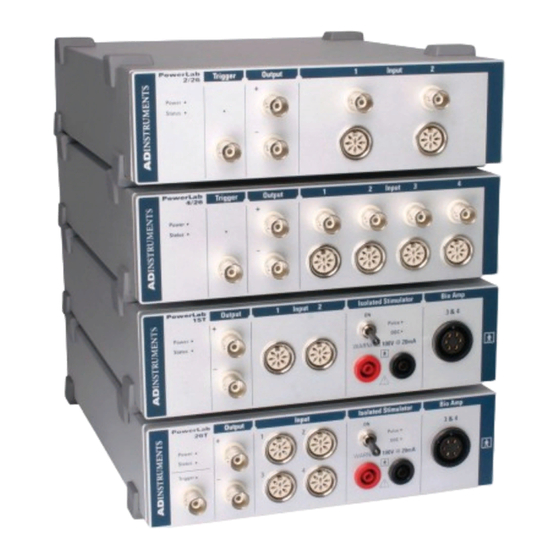
• The USB connection between the PowerLab and the computer. • The soft ware features specific to the built-in Isolated Stimulator and Bio Amp. Figure 3-1 PowerLab 26 series: PowerLab 2/26, 4/26 and 26T PowerLab Teaching Series - Owner’s Guide... -
Page 24: The Powerlab Self-Test
Restarting the PowerLab should clear a temporary problem. If the PowerLab does not seem to be getting power, or the Status indicator flashes red, even aft er restarting, refer to the ADInstruments website (www.adinstruments.com/ support/tsupport/education) or contact your authorized ADInstruments representative. -
Page 25: Connecting The Powerlab
LabChart application please refer to the LabChart Help. The soft ware controls specific to the signal conditioners built into the PowerLab 26T and 15T (an Isolated Stimulator and two Bio Amps) are described below. PowerLab Teaching Series - Owner’s Guide... -
Page 26: The Isolated Stimulator
Use the On and Off buttons to control pulse delivery, if necessary. • Independently of sampling: stimulation begins when On in the dialog is clicked, whether or not LabChart is sampling. PowerLab Teaching Series - Owner’s Guide... - Page 27 Choose how simulation should start Figure 3-4 The Stimulator dialog, Choose a stimulus Windows type preset Specify a custom stimulus waveform Configure the range of valid parameter values in the Parameter Settings dialog Set stimulus parameters PowerLab Teaching Series - Owner’s Guide...
- Page 28 Once you have set up stimulation using the Stimulator dialog, you can easily start or stop stimulation or change settings while sampling, by using the Stimulator Panel. Choose Stimulator Panel from the Setup menu to open it PowerLab Teaching Series - Owner’s Guide...
-
Page 29: The Bio Amp
You can stop the signal scrolling by clicking the Pause button at the bottom right of the data display area. Time-axis scaling controls work in a similar way to the Chart View. PowerLab Teaching Series - Owner’s Guide... -
Page 30: Setting The Range
10, 20, 50, 100, 200 and 500 Hz, and 1 and 2 kHz. These filters are useful for removing high-frequency signals, such as noise. DC Restore. Click DC Restore to reduce the time constant of the high-pass filter so that the filter can rapidly adjust to an altered baseline value. PowerLab Teaching Series - Owner’s Guide... - Page 31 Selecting Invert allows you to invert the signal on the screen. It provides a simple way to change the polarity of the recorded signal without having to swap the connections to the recording electrodes. PowerLab Teaching Series - Owner’s Guide...
-
Page 32: Technical Aspects And Specifications
PowerLab can and cannot do, and its suitability for particular purposes. You should not use it as a service manual: user modification of the PowerLab voids your rights under warranty. Figure 4-1 PowerLabs 15T and 26T PowerLab Teaching Series - Owner’s Guide... -
Page 33: How It Works
Because of these power limitations, you should not use the PowerLab as a power source for external devices other than those produced by ADInstruments. PowerLab Teaching Series - Owner’s Guide... -
Page 34: The Analog Inputs
20-volt pulse, given a ±10 V range setting. PowerLab Teaching Series - Owner’s Guide... -
Page 35: The External Trigger
In order for the external trigger to work, a voltage must be applied between the outer ring and the inner pin of the connector. Applying a voltage just to the center pin may not work. PowerLab Teaching Series - Owner’s Guide... -
Page 36: Bio Amp Input (Inputs 3 & 4)
Auto restore Isolation amplifier Signal Figure 4-5 Output Input Block diagram for one of the two Audio output(26T) Reference Bio Amplifiers (Input 3 & 4) IGND Gain control IGND HPF control IGND Isolation barrier PowerLab Teaching Series - Owner’s Guide... -
Page 37: The Isolated Stimulator Output
Stimulate Output Stimulator Block diagram of the Transformer Power Isolated Stimulator driver Supply Stimulus Isolator switch Current setting DAC Constant current source Stimulate Stimulator pulse INDICATORS safety control Out of Compliance Stimulate Isolation amplifier PowerLab Teaching Series - Owner’s Guide... -
Page 38: Powerlab Accuracy
20% and 80% of full scale) and recording the signal, you can use the units conversion feature of ADInstruments soft ware to convert and display transducer readings in the appropriate units. This will compensate for any minor inaccuracies in amplifier gain and transducer calibration. -
Page 39: I 2 C Expansion Connector
You should not attempt to run other external devices from the I2C port: it is designed for use only with ADInstruments front-ends. Only 50 mA maximum current can be provided through this bus, so it should not be used for third-party devices as they may draw more current. -
Page 40: Input Connectors
1 and 2 (but not inputs 3 or 4) by connecting them with the DIN-to-BNC adaptor. • When an ADInstruments pod is connected to either input 3 or 4, the corresponding Bio Amp input is turned off . USB Connection PowerLabs have a USB 2.0 port, and connect to a computer with USB ports or a PCI... -
Page 41: Earthing And Ground Loop Noise
This can reduce the inductive pick-up of mains frequency fields. Please consult a good text for further discussion of noise reduction PowerLab Teaching Series - Owner’s Guide... -
Page 42: Specifications
1 M150 pF (Inputs 3 & 4) Input Coupling: DC or 0.15 Hz (soft ware selectable) -3dB bandwidth: 49 kHz DC drift : Soft ware corrected CMRR: > 105 dB at a gain of 100 Interchannel crosstalk: > 90 dB PowerLab Teaching Series - Owner’s Guide... - Page 43 ±0.0006 % FSR (INL) Available sampling rates: 100 000 samples/s down to 10 min/sample Bio Amp Input- Inputs 3 & 4 (PowerLab 15T & 26T) Number of channels: Input configuration: Diff erential with common isolated ground PowerLab Teaching Series - Owner’s Guide...
- Page 44 Mains Audio output (26T only): Stereo ouput socket supplying an analog audio signal from both bio amp channels. Suitable for earphones, headphones and most externally powered speakers. Output is 300 mV at full scale PowerLab Teaching Series - Owner’s Guide...
- Page 45 Provides physical disconnection of the stimulator from the subject. External Trigger (not on PowerLab 15T) Trigger mode: TTL level or contact closure, soft ware selectable Trigger threshold: +1.3 V (rising edge), +1.1 V (falling edge) Hysteresis: 0.3 V PowerLab Teaching Series - Owner’s Guide...
- Page 46 Less than 300 μA Safety device compatibility: 10 mA Transport and Storage conditions: 0–40 °C, 0–95% humidity (non-condensing) Equipment: The PowerLab must be connected to safety earth via the power supply cable to ensure electrical safety. PowerLab Teaching Series - Owner’s Guide...
- Page 47 Avoid operating near high voltage, RF or strong magnetic fields that may cause interference. Method of Disposal: Forward to recycling centre or return to manufacturer. ADInstruments reserves the right to alter these specifications at any time. PowerLab Teaching Series - Owner’s Guide...
- Page 48 3 A/m 3 A/m Power frequency magnetic (50/60Hz) magnetic fields should be at field levels characteristic of a IEC 61000-4-8 typical location in a typical commercial or hospital environment. Table 4-1 Immunity Test compliance PowerLab Teaching Series - Owner’s Guide...
-
Page 49: Electromagnetic Compatibility
= 1.17√P d = 2.33√P 0.01 W 0.1 m 0.2 m 0.1 W 0.4 m 0.7 m 1.2 m 2.3 m 10 W 3.7 m 7.4 m 100 W 11.7 m 23.4 m PowerLab Teaching Series - Owner’s Guide... -
Page 50: Troubleshooting
• Turn everything off. Check to see that all cables are firmly seated and screwed in. BNC cables from the front end must be connected to a positive input on the PowerLab. Make PowerLab Teaching Series - Owner’s Guide... - Page 51 The PowerLab, or a portion of it, is faulty • This is the least likely event. Contact your ADInstruments distributor to arrange for repairs On starting up the soft ware, an alert indicates that there is a problem with the PowerLab or driver The correct drivers are not installed on your computer (LabChart has them built in).
- Page 52 You may be using the wrong Bio Amp cable. The 3-lead Bio Amp cable used with the single Bio Amp has a different pin arrangement and cannot be used with the Dual Bio Amp/ Stimulator front- end. • Use the correct, supplied 5-lead Bio Amp cable. PowerLab Teaching Series - Owner’s Guide...
-
Page 53: Powerlab Led Error Sequences
For example, Abs (–13) => 01101 => short, long, long, short, long. In this state the PowerLab will not respond to any communications. PowerLab Teaching Series - Owner’s Guide... - Page 54 LNG, SHRT, SHRT, SHRT, SHRT EEROM wouldn't read Non-Fatal eEEROMBad LNG, SHRT, SHRT, LNG, SHRT ADC FIFO capacity/speed tests failed Non-Fatal eADCSysBad LNG, LNG, LNG, LNG, SHRT ADC won’t read consistently Non-Fatal eChanNoisy PowerLab Teaching Series - Owner’s Guide...
-
Page 55: Glossary
A type of transducer using a Wheatstone bridge circuit. In its basic form, the bridge consists of four two-terminal elements (usually strain gauges) connected to form a quadrilateral. An excitation source is connected across one diagonal, and the transducer out- put is taken across the other. PowerLab Teaching Series - Owner’s Guide... - Page 56 An ancillary device that extends PowerLab capabilities, providing additional signal conditioning and features for specialized work. Front-ends are recognized automatically by the PowerLab system and seamlessly integrated into its applications, operating under full software control. PowerLab Teaching Series - Owner’s Guide...
- Page 57 LabChart. An ADInstruments software application that emulates a multichannel chart record- er, with other powerful options. (Macintosh and Windows versions differ slightly.) Lt. An ADInstruments cloud based application for teaching that integrates an experiment pro- tocol, real-time data acquisition, analysis and reporting as interactive pages in a web browser.
Need help?
Do you have a question about the POWERLAB TEACHING SERIES and is the answer not in the manual?
Questions and answers