Table of Contents
Advertisement
Quick Links
Advertisement
Table of Contents

Related Manuals for ADInstruments ML206


Summary of Contents for ADInstruments ML206
- Page 1 Gas Analyzer Owner’s Guide Gas Analyzer Owner’s Guide...
- Page 2 Th is document was, as far as possible, accurate at the time of release. However, changes may have been made to the soft ware and hardware it describes since then. ADInstruments NZ Limited reserves the right to alter specifi cations as required. Late- breaking information may be supplied separately.
-
Page 3: Table Of Contents
Contents Safety Notes 1 Overview How to Use Th is Guide......... 14 Checking the Gas Analyzer . - Page 4 B Troubleshooting C Specifi cations Warranty Index Gas Analyzer Owner’s Guide...
-
Page 5: Safety Notes
ADInstruments products are NOT intended to be used as medical devices or in medical environments. Th at is, no product supplied by ADInstruments is intended to be used to diagnose, treat or monitor a subject. Furthermore no product is intended for the prevention, curing or alleviation of disease, injury or handicap. - Page 6 Safety Symbols Devices manufactured by ADInstruments that are designed for direct connection to humans are tested to IEC 601-1:1998 (including amendments 1 and 2) and 60601-1-2, and carry one or more of the safety symbols below. Th ese symbols appear next to those inputs and output connectors that can be directly connected to human subjects.
- Page 7 during defi brillator discharges may damage the input stages of the amplifi ers. Th is may result in a safety hazard. • Never use damaged Bio Amp cables or leads. Damaged cables and leads must always be replaced before any connection to humans is made.
- Page 8 Th erefore, under no circumstances should any other transformer be used with the Stimulus Isolator. For a replacement transformer plug pack please contact your nearest ADInstruments representative. General Safety Instructions To achieve the optimal degree of subject and operator safety, consideration...
- Page 9 While it is not possible to cover all arrangements of equipment in a system, some general guidelines for safe use of the equipment are presented below: • Any electrical equipment which is located within the SUBJECT AREA should be approved to IEC60601-1. •...
- Page 10 Cleaning and Sterilization ADInstruments products may be wiped down with a lint free cloth moistened with industrial methylated spirit. Refer to the Data Card supplied with transducers and accessories for specifi c cleaning and sterilizing instructions.
- Page 11 Equipment (WEEE) Directive symbol requires separate waste collection. For a product labeled with this symbol, either forward to a recycling center or contact your nearest ADInstruments representative for methods of disposal at the end of its working life. WEEE Directive...
-
Page 12: Overview
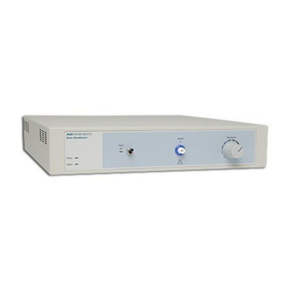
C H A P T E R Overview Th e ADInstruments ML206 Gas Analyzer is a set of transducers used for the measurement of respiratory gases. It contains infrared carbon dioxide and visible spectrum oxygen detectors, and connects to any PowerLab®... -
Page 13: How To Use This Guide
Pick up the Gas Analyzer, tilt it gently from side to side, and listen for anything that appears to be loose. If you have found a problem, contact your authorized ADInstruments representative immediately, and describe the problem so arrangements can be made to replace or repair the unit. -
Page 14: The Back Panel
If the internal fuses are suspected of having blown, the unit should be returned to your local ADInstruments representative. Status Indicator Th e Status indicator glows green when the Gas Analyzer is connected to a PowerLab and has been recognized by LabChart. - Page 15 C Input and Output Ports Th e I C ports allow front-ends manufactured by ADInstruments to be chained together and supplied with power and communications from the PowerLab. Only 50 mA maximum current can be provided through this bus, so it should not be used for third-party devices drawing more current.
-
Page 16: Using The Gas Analyzer
C H A P T E R Using the Gas Analyzer Th is chapter guides you through connecting your Gas Analyzer to your PowerLab and performing an initial check to make sure that there are no problems or omissions. IMPORTANT: Always turn off both the PowerLab and Gas Analyzer before connecting or disconnecting either unit. -
Page 17: Connecting The Gas Analyzer
PowerLab to the I2C Input connector on the back panel of the Gas Analyzer. You are able to use other ADInstruments front-ends at the same time as the Gas Analyzer by connecting them either before or aft er the Gas Analyzer in the I C chain. -
Page 18: Connecting To Other Recorders
Connecting to Other Recorders Analog signals from the Gas Analyzer are linear and proportional to CO and O partial pressures (CO output of 0–1 V is equivalent to 0–10% CO and O output of 0.05–1 V is equivalent to 5–100% O ). -
Page 19: Recording
It is also recommended that a PFT bacterial fi lter (available as part of the Spirometer Kit from ADInstruments, for example) be fi tted in the circuit aft er the face mask or mouthpiece so as to reduce bacterial build-up inside the Gas Analyzer. -
Page 20: Calibration
Units… • Click the button to open the Units Conversion dialog, with which you can enter diff erent values for the channel, as described under “Calibrating with LabChart”, page 22; doing so deselects the Use default units checkbox. To revert to the default settings again, and so replace any previous settings made in the Units Conversion Use default units dialog, select the... - Page 21 Default Calibration Settings Both transducers produce linear outputs that are directly proportional to the concentrations of the CO and O in the sample. Th e CO transducer has an output of 0–1 V for 0–10% CO and the O transducer has an output of 0.05–1 V for 5–100% O .
- Page 22 ADInstruments.com) to ensure the calibration values overwrite the default values. Details of how to use the extension can be found in the MP Calibration Guide that gets installed into the ADInstruments’ Documentation folder. Once the calibration values are entered and applied, they can be saved as a LabChart Settings fi le for later reuse.
-
Page 23: Care And Maintenance
C H A P T E R Care and Maintenance Th e Gas Analyzer has been designed to eliminate much of the usual maintenance associated with sensitive measuring devices. Th e only maintenance that you may need to perform is the replacement of the hydrophobic and bacterial fi lters. - Page 24 Th e only maintenance you should perform on the Gas Analyzer is the replacement of the external fi lters in the gas pathway. It is recommended that the unit be returned to your ADInstruments distributor annually for servicing. Note that removing the cover of the Gas Analyzer will void the warranty.
-
Page 25: A Technical Details
A P P E N D I X Technical Details Th is Appendix describes some technical aspects of the Gas Analyzer’s operation. You do not need to know the material in this section in order to operate the Gas Analyzer and it is not intended in any way as a service guide. -
Page 26: How It Works
How it Works Th e Gas Analyzer has an infra-red transducer to measure CO concentration and a visible spectrum transducer to measure oxygen concentration. It has a response time of about 0.2 s (at ~200 ml/min) and can be used to indicate and O trends in exercising humans and small animals. -
Page 27: Considerations When Using The Gas Analyzer
Considerations When Using the Gas Analyzer • Th e sample inlet and exhaust ports on the Gas Analyzer should remain clear. • Unnecessary dead-space in the gas path should be kept to a minimum. • Chemical contamination and rubber compounds should be avoided. •... - Page 28 LabChart application again. If you cannot fi nd a solution to your problem in this appendix, or in your PowerLab owner’s guide or the LabChart Help Center, please contact your ADInstruments representative. Appendix B Troubleshooting...
- Page 29 • Check that the power cable is fi rmly connected at the back of the Gas Analyzer. If the internal fuses are suspected of having blown, the unit should be returned to your ADInstruments distributor for servicing. Drift in the Output Signal Positive Drift : Contamination build up in the sample chambers of the transducers will cause a positive drift proportional to the build up.
- Page 30 A P P E N D I X Specifi cations Specifi cations Sampling system: One CO and one O transducer fed from a damped, micro-vacuum pump. Gases: Must be non-corrosive and non- fl ammable. A moisture removal scheme must be employed before the sampling inlet.
- Page 31 System Type: Infrared, optical Range: 0–10% CO Output: Linear, 0–1 V (0–10% CO Resolution: 0.1% CO Linearity: ±0.1% CO Initial drift : <±0.1% CO in fi rst 24 hours, then <±0.2% during following 7 days. Response time (10–90%): 90–130 ms @ 200–50 ml/min - transducer alone;...
- Page 32 Physical Confi guration Dimensions (h × w × d): 60 mm × 300 mm × 300 mm (2.36" × 11.8" × 11.8") Weight: 5 kg ADInstruments reserves the right to alter these specifi cations at any time. Appendix C Specifi cations...
- Page 33 Warranty Product Purchase and License Agreement Th is Agreement is between ADInstruments NZ Limited [‘ADI’] and the purchaser [‘the Purchaser’] of any ADI product or solution — soft ware, hardware or both — and covers all obligations and liabilities on the part of ADI, the Purchaser, and other users of the product.
- Page 34 Products supplied by ADInstruments are NOT intended to be used as medical devices or in medical environments. Th at is, no product supplied by ADInstruments is intended to be used to diagnose, treat, or monitor a subject. Furthermore no product is intended for the prevention, curing or alleviation of disease, injury or handicap.
- Page 35 Hardware Warranty Limitations Th is warranty applies only to the ADI hardware specifi ed in this document and used under normal operating conditions and within specifi cation. Consumables, electrodes and accessories are not covered by this warranty. Th ird party equipment may be covered by the third party manufacturer’s warranty.
- Page 36 Third Party Products (Including Transducers) Products not manufactured by ADI are covered by the manufacturer’s warranty. Accessories and Consumables Accessories and Consumables are not covered by any type of warranty. General Limitations ADI products are produced to high standards, and should perform as described in the supplied documentation.
- Page 37 FROM THE EQUIPMENT AND SOFTWARE. WITHOUT LIMITING THE FOREGOING PROVISIONS, ADI MAKES NO WARRANTY THAT THE EQUIPMENT OR SOFTWARE WILL BE ERROR-FREE OR FREE FROM INTERRUPTIONS OR OTHER FAILURES OR THAT THE SOFTWARE OR EQUIPMENT WILL MEET YOUR REQUIREMENTS. UNDER NO CIRCUMSTANCES AND UNDER NO LEGAL THEORY, WHETHER IN TORT, CONTRACT, OR OTHERWISE, SHALL ADI OR ITS SUPPLIERS BE LIABLE TO PURCHASER OR TO ANY OTHER PERSON FOR LOSS OF PROFITS, LOSS OF GOODWILL, OR...
- Page 38 ADInstruments offi ce or Authorized Distributor. For contact details see ADInstruments.com Copyright © ADInstruments NZ Ltd, 2020. All rights reserved. PowerLab, LabChart and ADInstruments are registered trademarks of ADInstruments NZ Ltd. Windows 8, Windows 7, Windows Vista and .NET Framework are trademarks of Microsoft Corporation.
- Page 39 Index analog outputs 16 Nafi on 19 back panel 15 oxygen dialog 20 bacterial fi lter 20, 26 oxygen transducer 28 calibrating 21–23 power connection 16 Carbon Dioxide dialog 20 power indicator 15 carbon dioxide transducer 28 PowerLab connection 18 cleaning 10, 26 problems 31 connections...
Need help?
Do you have a question about the ML206 and is the answer not in the manual?
Questions and answers