Table of Contents
Advertisement
Quick Links
Advertisement
Table of Contents

Related Manuals for ADInstruments AD1000


Summary of Contents for ADInstruments AD1000
- Page 1 AD1000 Multifunctional Test Platform User’s Manual ...
-
Page 2: Warranty
AD INSTRUMENTS shall not be liable for errors contained herein or for incidental or consequential damages in connection with furnishing, performance, or use of this material. The battery is a consumable part and is not subject to the AD1000 warranty. ... -
Page 3: Environmental Conditions
Symbols. Do Not Operate in an Explosive Atmosphere Do not operate AD1000 in the presence of flammable gases or fumes. Do Not Remove AD1000 Cover Operating personnel must not remove instrument covers. Component replacement and internal adjustments must be made only by qualified service personnel. -
Page 4: Laser Safety Announcements
AD1000 is a laser instrument. Users should avoid looking directly into the optic output. And the use of microscope or magnifier should also be avoided, for the use of such devices can focus a highly intense beam onto the retina, which may result in permanent eye damage. -
Page 5: Electric Safety Announcements
Battery: Battery of AD1000 is rechargeable lithium battery. If unused for a long time, battery should be recharged before use. If AD1000 is not in use for more than two months, it should be recharged to maintain adequate battery volume. Do not recharge batteries for more than 8 hours. -
Page 6: Agreement And Statement
AD1000 User’s Manual Agreement and Statement Button or menu: The operating units in GUI that can be clicked by stylus, indicated by letters in square brackets, e.g. [Setup] and [Start]. ... -
Page 7: Table Of Contents
AD1000 User’s Manual Contents Notices ..........................ii Warranty..........................ii Safety Instructions ......................ii Laser Safety Announcements ..................iv Electric Safety Announcements ..................v Agreement and Statement....................vi 1 General Information...................... 12 1.1 Scope of this Manual ....................12 1.2 Unpacking and Inspection .................. - Page 8 4.3.1.3 Inspection Events ..................32 4.4 Optic Fiber Link and Event Types................32 5 Instruction of OTDR Modules of AD1000 ............32 5.1 Main Features of OTDR Module ................32 5.2 Measurement Mode of OTDR module ..............33 5.2.1 Auto Mode and Manual Mode..............
- Page 9 AD1000 User’s Manual 9.1 Common using parameters for OTDR testing............. 46 9.2 OTDR test parameters Configuration ..............46 9.3 OTDR display and other Configuration ..............47 9.4 Real time and average test mode................47 9.5 Range Configuration....................48 9.6 Pulsewidth Configuration ..................
- Page 10 16.6 Loss Test of MPN Module..................93 17 File Management ......................94 17.1 Transfer Files or Folders between AD1000 and USB Storage Device ..94 17.2 Transfer Files or Folders between AD1000 and PC........95 17.3 Delete Saved Files....................96 ...
- Page 11 AD1000 User’s Manual 18.4 Cleaning Tools ......................97 18.5 Cleaning Procedure ....................97 18.6 Battery Charging Instructions................97 18.7 Battery Instruction ....................98 18.8 Charge Battery ....................... 98 18.9 Battery Calibration ....................98 18.10 Change Battery ....................99 18.11 Calibration Requirements ...................
-
Page 12: General Information
This instrument has been carefully packed in accordance with standard shipping procedures. Examine AD1000 for damage that may have occurred during shipment. If you find any damage or AD1000 is not working, or if any of the following items are not included, please contact your representative of Shineway Technologies, Inc. -
Page 13: Product Appearance
activation, maintenance and troubleshooting. AD1000 is easy to handle with large touch screen, accurate turning knob and smart user-interface. Windows CE system, large built-in and extended memory enable convenient test data storage, access and transfer to PC via USB for further analysis and reporting. -
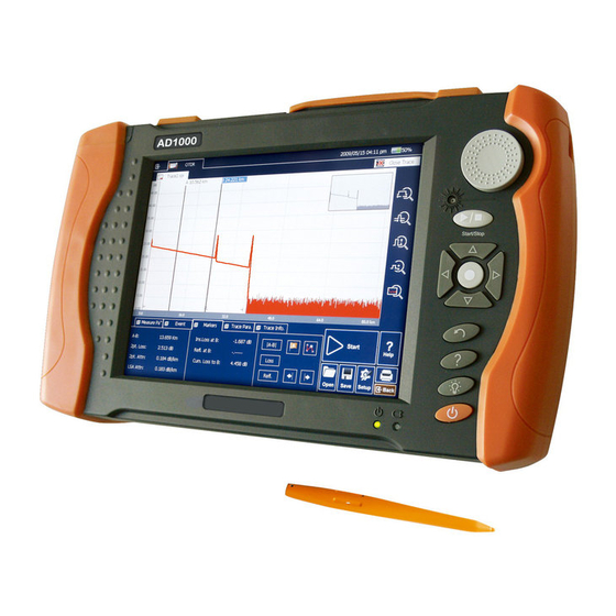
Page 14: Front Panel Indicators Introduction
AD1000 User’s Manual LCDTouchScreen Laser Indicator 3-Way Turning Knob Start/Stop Direction Keys/Enter Return Help Backlight Power On/Off Power Indicator Charging Indicator Power On/Off key is lower than other keys to avoid misoperation. -
Page 15: Front Panel Keys Instruction
AD1000 User’s Manual Icon Status Meaning Red, constant Charging, with power adaptor Red, blinking Low battery Charging Indicator Charging complete, with Green, constant power adaptor Power adaptor unplugged or connection is poor ... -
Page 16: Operating Parts Instructions
LCD and touch screen. u Please apply adequate force with stylus on the touchscreen, u Only use AD1000 stylus, do not use other device. Sharp object like ball pen tip may smear or damage the touchscreen. ... - Page 17 USB Host mouse, keyboard and USB interface testing devices (Driver needed) ·Optical Ports AD1000 is equipment with FC/PC connectors (Interchangeable SC, ST) Name Appearance Icon Description OTDR OTDR port ...
-
Page 18: Gui Icons Instruction
AD1000 is a laser instrument. Users should avoid looking directly into the optic output. And the use of microscope or magnifier should also be avoided, for the use of such devices can focus a highly intense beam onto the retina, which may result in permanent eye damage. -
Page 19: Power Instruction
The battery power indicator displayed on LCD screen will turn red (Low battery) when the battery power is insufficient and AD1000 may automatically power off. Ø If unused for a long time, AD1000 may not power on properly, please connect power adaptor and recharge the battery. ... -
Page 20: Basic Operation
2.3 Enter and Exit Power Saving Mode When power is on, user can set AD1000 to power saving mode and return to normal status. In power saving mode, the LCD backlight will turn off. - 20 - ... -
Page 21: Adjust Lcd Brightness
2.5 Start Application When AD1000 is powered on, system will load the main program of MTP-Suite CE (Apllication software package) and enter main interface, as shown in Fig. 2.1 - 21 - ... - Page 22 AD1000 User’s Manual Launch OTDR program: 1. Select “Modules” label and then “OTDR Module” in main menu, the part will be highlighted 2. Then click to start program Launch Multifunctional module or optical connector inspector module application program ...
-
Page 23: Install Usd Keyboard/Mouse
Install USB keyboard or mouse on AD1000 Connect keyboard or mouse to the USB port, the port is on the top of AD1000. u No need to close AD1000 before connecting the keyboard and mouse. - Page 24 AD1000 User’s Manual Fig. 2.2 Printer and setting interface 5. In Printer area, until now there is no default printer. Click [ ], it will appear window as shown below: ...
-
Page 25: Common Settings And Special Settings
u AD1000 only support USB port printer with PCL language; till now the printers passed the test are LaserJet 1022,Hp Laser P2015d and etc. u If the printer is not connected well, pull out the USB cable and reconnect the printer. -
Page 26: Select Language
3.3 Automatic Power Saving Setting The feature is designed to save the battery power. When power is on, AD1000 will automatically enter power saving mode after its idle time exceeds pre-set value. - 26 - ... -
Page 27: Recalibrate Touch Screen
AD1000 User’s Manual Setting Power Saving Mode: Click to enter into setting menu In power saving area of setup menu, choose preferred option in “Turn Off LCD” Press “OK”, Exit setup menu and opening power saving mode. -
Page 28: Serious Deviation Of Touch Screen
AD1000 User’s Manual 3.5 Serious Deviation of Touch Screen When deviation of touch screen is serious, it is difficult to calibrate only using stylus. You can use USB mouse to enter into calibration window, and continuing to calibrate with pen ... -
Page 29: Load Default
OTDR (Optical Time Domain Reflectometer) is a measurement instrument for identifying optic fiber transmission features. AD1000 is mainly used to measure attenuation of a whole optic fiber chain and provide attenuation details relating to length, namely detect, locate and measure any event in optic fiber chain (Events refer to faults caused by splicing, connectors and bending). -
Page 30: Measurement Application Of Otdr
AD1000 User’s Manual Information relating to distance is obtained through time information (That’s the reason why there is “Time Domain” in the name of OTDR). Fresnel reflection occurs at the boundary between two media of different IOR (For example, connections of faults, connectors, or optic fiber end). -
Page 31: Basic Definition And Classification Of Events
AD1000 User’s Manual 4.3 Basic Definition and Classification of Events 4.3.1 Events Events refer to any abnormal points causing attenuation or sudden change of scattering power besides the normal scattering of optic fiber, which include all kinds of losses like bending, connections and ruptures. -
Page 32: Inspection Events
OTDR sends off a light pulse into the optic fiber to be inspected, and then receive returning light signals, and starts calculating the “event” distance. The farther the distance is, the longer time need for scattered light to be received by AD1000. Event distance can be calculated according to the time of receiving events signals. -
Page 33: Measurement Mode Of Otdr Module
AD1000 User’s Manual imprecise test trace, even permanent damage for the OTDR 5.2 Measurement Mode of OTDR module For convenience of customers use, OTDR offer many kinds of measurement mode. These modes can be used with combination ... -
Page 34: Otdr Interface
AD1000 User’s Manual When using the In-service mode, the fiber must be connected to the right port of 1625nm. If it is connected to other port; it may result in imprecise test trace, even permanent damage for the OTDR. -
Page 35: Icons Instruction In Otdr Interface
AD1000 User’s Manual 5.4 Icons Instruction in OTDR Interface Icon Description Start testing Stop testing ... -
Page 36: Trace Processing
6 Prepare to Use OTDR 6.1 Connectors Instruction The optical ports equipped on AD1000 are FC/PC (Interchangeable SC, ST) 6.2 Cleaning and Connecting to Optical Fiber To insure measurement accuracy, please clean and connect fiber properly before testing. -
Page 37: Test With Otdr
AD1000 User’s Manual Connecting fiber to OTDR port is tool-free. Ø Please refer to “Maintenance and Calibration” for optical port and connector cleaning. Ø Clean connectors and check if fiber connector type is FC/PC ... -
Page 38: Trace Processing
AD1000 User’s Manual Fig 7.1 OTDR Trace Acquisition Interface u During testing, the averaging trace shows in the trace display area and refresh at certain intervals, the trace after testing finishes is the final trace. -
Page 39: Unsaved Traces
AD1000 User’s Manual new test. 7.3 Unsaved Traces Unsaved traces will be titled as “*U_xxxx” (xxxx stands for the current testing wavelength) which is displayed on the left upper corner of trace display area. -
Page 40: Auto Naming
AD1000 User’s Manual Fig 7.2 Save dialog window Operation Notes: ü Title bar will show the current folder path, as shown in Fig 7.2: “\SDMMC_DISK\Traces\”. ü System will automatically enter newly created folder. -
Page 41: Open Saved Trace
Setup checking/unchecking “Multi-trace” in Display Option. u User can open and view “.jpg” format trace though “File Explorer” on {Program} label in AD1000 main interface. “.jpg” format trace can be also loaded to PC for viewing. 7.7 Trace Viewing and Analysis Operation ... -
Page 42: Information And Function Windows
AD1000 User’s Manual Show A/B marker: Ø Click {Markers} label in OTDR main interface and markers or marker labels will show in trace display area. Ø Or press turning knob once. Move marker quickly: ... -
Page 43: Switch Information And Function Windows
AD1000 User’s Manual Information and function windows description: Label Function Measurement parameters: Meas. Para. Mode, Wavelength, Range, Pulsewidth, Averaging Time and etc. Events Add event, modify event, delete event and analyze event. Markers A/B switch, move, lock, loss and reflection analysis. -
Page 44: Upload Trace To Pc
AD1000 User’s Manual 7.9 Upload Trace to PC On computer, user can manage the trace file flexibly. Copy or move the trace to computer: 1. User can copy the saved trace to computer via USB by PC software ... -
Page 45: The Procedures Of Auto Testing Mode
AD1000 User’s Manual After Auto mode started, according to the situation of optical fiber link which connecting the equipment, application program will estimate the optimum setting automatically and it will need around 5s. If the testing was cut off, any date won’t be displayed. -
Page 46: Common Using Parameters For Otdr Testing
AD1000 User’s Manual Correct parameters setting is the essential condition of optical fiber accurate measurement. So, when test manually, must set parameters accord to requirements. 9.1 Common using parameters for OTDR testing. Following testing parameters displaying on {Meas. Para.} option card on the OTDR ... -
Page 47: Otdr Display And Other Configuration
AD1000 User’s Manual 9.3 OTDR display and other Configuration Including setting of save method, testing display area and etc. Parameters setting in this part won’t affect the testing result. Setting Content If be selected, the trace files saving will adopt auto name, ... -
Page 48: Range Configuration
Click on the right range settings. u “Auto” is Auto test mode of OTDR, select this function, AD1000 will select a proper test range intelligently and the proper pulse width to test. The whole process no need user participate u... -
Page 49: Averaging Time Configuration
AD1000 User’s Manual u When the distance range is “Auto”, the pulse width will be “Auto”, no need the user to set. There will be different pulse width options accord to different distance range. 9.7 Averaging Time Configuration ... -
Page 50: Non-Reflection Threshold (Splice Loss Detecting Threshold) Configuration
AD1000 User’s Manual 9.11 Non-reflection Threshold (splice loss detecting threshold) Configuration This configuration has direct impact on the listing of insertion loss events. Only events greater than this threshold will be listed. The value configuration zone is 0.00 to 5.00dB... -
Page 51: Use Otdr Test Fttx-Pon Network Optical Fiber Link
For normal optical fiber link, end threshold configuration can be 3.0dB, as to PON network optical fiber link with branching unit, it need to set the end threshold to a proper value and then AD1000 can locate the end event correctly. Please refer to follow end threshold configuration sheet. -
Page 52: Trace Analysis And Event Operation
AD1000 User’s Manual value reference value ≥9dB 12dB 100ns,300ns 1:16 ≥12dB 15dB 100ns,300ns 1:32 ≥15dB 18dB 300ns,1us 1:64 ≥18dB 21dB 300ns,1us Table 10.1 Recommended parameter values for PON network optical fiber link ... -
Page 53: Simultaneous Display Multi Traces
11.2 Simultaneous display multi traces In order to let user compare trace files, AD1000 support opening and displaying multi traces. When open multi traces, current trace is red, the icon in front of the file name is red, other icons are grey. -
Page 54: Close Trace File
AD1000 User’s Manual System can open 4 traces at the same time. When need to open other traces, please close some opened traces. 11.3 Close trace file Close trace file: Click [close trace] button on the upper right corner of the interface to close the trace file. -
Page 55: Switch And Move Markers
AD1000 User’s Manual In {event} options, there are various parameters of events listing, including event type, number, position, insert loss, reflection loss, attenuation and accumulation and etc. When switch to {event}, application program will display a marker on the tracing graph. -
Page 56: Switch And Move The Marked Point
u For easier using, the position of Markers will be remembered, when open AD1000 and trace next time, the Markers will maintain the position operated last time. u There is marked point when proceed the loss or reflection analysis. -
Page 57: Lock Ab Markers
AD1000 User’s Manual When the Markers on the left side outside the window, there will be a sign on the left margin of the window: A←or B← When the Markers on the right side outside the window, there will be a sign on the right margin of the window: →A or →B... -
Page 58: Cross Frame To Zoom The Trace
AD1000 User’s Manual 11.10 Cross frame to zoom the trace In the trace display area, magnify the traces by cross frame from upper left to lower right. In the trace display area, contract the trace from upper right to lower left ... -
Page 59: Zoom In Trace Horizontally
u When user turns off AD1000, the zoom info won’t be reserved. Turn on AD1000 again; trace window will revert to whole trace status. u When user changes wavelength, pulse width and time, as long as the distance is not changed, auto memory of zoom status will be effective u... -
Page 60: Move The Magnified Trace Window
AD1000 User’s Manual 11.13 Move the magnified trace window After the trace magnified, the trace window will only display part of the trace. There are two ways to move the trace window: Use stylus or mouse to operate in navigation window. - Page 61 AD1000 User’s Manual caused by transmission, splice, connector or crack. If event was not in the certain threshold, it was defect event. Fig 11.2 Events options As to every event in the even sheet, display follows info: ...
-
Page 62: Display The Event On The Trace And Locate Event In Even Sheet
AD1000 User’s Manual 11.14.1 Display the event on the trace and locate event in even sheet Through rolling the event sheet, user can check the relative info about all events tested on the trace. When an event selected, there will be Markers appear on the trace which above the event. - Page 63 AD1000 User’s Manual Fig 11.3 Add event 2. Fill in the event info in the add event dialog window. Fig 11.4 Add Event Dialog Window ...
-
Page 64: Modify The Event
AD1000 User’s Manual 11.14.3 Modify the event User can modify the event in the event sheet manually. For example, when there is an event analysis result unmatched the observed result, user can modify it through this function. -
Page 65: Delete Event
AD1000 User’s Manual Fig 11.6 Modify Event 3. Press [Enter] to save and back to main window after edit finished, the event will appear in the event list. If pressed [cancel], it will quit without save. -
Page 66: Analysis Detecting Threshold Configuration
AD1000 User’s Manual 3. Press “Yes“ when the program hint or press “No“ don’t delete event and go back to main interface. ... -
Page 67: Reanalyze The Trace
AD1000 User’s Manual 2. Set these parameters in the parameters analysis part. In the ralative edit frame, enter value needed or press[default value] revert the default value. ... -
Page 68: Analyze The Optical Fiber In Specific Optical Fiber Link
AD1000 User’s Manual u If user wished to find some new events or filter some events he didn’t pay attention, please change the analysis detecting threshold first and then to proceed the analysis. u Effected by instrument features or detecting threshold, the analytic result may be inconsistent to the result user preconceive ... -
Page 69: Set The Length Unit
AD1000 User’s Manual Ø Zoom toolbar: It can display or hide the zoom icon area which on the right side; will get maximized trace display area after hide the zoom toolbar. The zoom toolbar is displayed under default status. -
Page 70: Display Or Switch The Trace
AD1000 User’s Manual u Some certain values such as pulse width, wavelength and etc won’t change along with the distance. Pulse indicated by second, wavelength indicated by nm u When select m as length unit, system will display km in some place ... - Page 71 AD1000 User’s Manual Ø Link length: The length of optical fiber link calculated after test Ø Link loss: The total loss of the link starting point to the link end Ø Link attenuation: Average loss of the total link, indicated as function of distance Ø...
-
Page 72: Manual Trace Analysis
AD1000 User’s Manual 12 Manual Trace Analysis User can use markers and zoom tools to measure splice loss, attenuation and reflection, or use markers to locate event position and relative power level. 12.1 Use Markers ... -
Page 73: Measure Insertion Loss (2-Point And 5-Point Method)
AD1000 User’s Manual 12.3 Measure Insertion Loss (2-point and 5-point method) Insertion loss (unit: dB) is calculated by measuring the signal level of Rayleigh backscatter (RBS) and the magnitude of reduction. Insertion loss can be created by reflection and non-reflection events. - Page 74 When [Loss] button is pressed, AD1000 will show the marking points to measure the event loss. When Marker A is selected, the screen will display the 4 marking points related to Marker A. When Marker B is selected, the screen will display the 4 marking points related to Marker B.
- Page 75 AD1000 User’s Manual 3. Zoom the trace to view the event clearly, move Marker A to the end of linear part of the trace before the event; 4. Move the first marking point to the beginning of the linear part of the trace before the event;...
-
Page 76: Measure Attenuation (2-Point And Lsa Method)
AD1000 User’s Manual 12.4 Measure Attenuation (2-point method) 2-point method measures the attenuation between Marker A and B calculated by all the loss over the distance between Marker A and B (Unit: dB/Km). ... -
Page 77: Measure Reflectance
AD1000 User’s Manual 12.5 Measure Reflectance Reflectance is the ratio of reflected power (Pr) to incident power (Pi) of an event (such as a connector). Reflectance = 10 log (Pr/Pi). 1. Click {Markers} label in OTDR main interface to show Marker A and B. -
Page 78: Trace File Management
AD1000 User’s Manual Fig 12.6 Measure reflectance For non-reflection events, reflectance will show as “-----”。 13 Trace File Management User can save, open, rename and delete trace file after acquisition. -
Page 79: Copy, Move, Rename And Delete Trace
For more information, please refer to the Help file on AD1000. Way 2: User can connect AD1000 to PC, AD1000 will be recognized as a mobile device. User can copy, move, rename and delete files in PC’s Windows System. -
Page 80: Check Disk Space
4. Click “OK” to exit disk properties. It’s suggested to check disk space utilization status from time to time and transfer or back up files to avoid insufficient disk space when AD1000 is in use. ... -
Page 81: Trace Information
AD1000 User’s Manual 14.1 Trace Information After trace acquisition, user can add or update tested fiber information which includes: Cable ID, Fiber ID, Fiber Type, Start Location, End Location and Operator. 14.2 Check and Edit Trace Information ... -
Page 82: Print Otdr Report
User can also use MTP-Suite to edit and save trace information. 14.3 Print OTDR Report AD1000 support direct connection to USB printer for printing. OTDR report includes trace information, measurement parameters, trace, markers information, event list and etc. - 82 - ... - Page 83 A. To print current file, please check “Print current file” option and only one trace will be printed. B. To print unopened traces saved in AD1000, please check “Batch print” option which support up to 8-traces printing. 4. Print Option: ...
- Page 84 AD1000 User’s Manual Fig 14.4 Printing options 5. Press [Print] button to start printing. During printing, system will promote a message as “Printing…Pease wait”, shown in Fig 14.5. Fig 14.5 Printing ...
-
Page 85: Vfl Application
The maximum detection range for AD1000 VFL is over 5Km, it is a practical tool for fiber identification, detecting and highlighting breaks, tight bends, splices or defective connectors in optical fibers. -
Page 86: Instruction Of Mpn Module Of Ad1000
AD1000 User’s Manual 16 Instruction of MPN Module of AD1000 16.1 Main Features of MPN Module Ø Simultaneous Triple-play PON signals at 1310, 1490, 1550nm wavelength measurement Ø Burst mode 1310nm upstream signal detection & measurement Ø... -
Page 87: Pon Power Meter Of Mpn Module
to start the measurement. Click [ ]button or Re-Press “ ( ” Start/Stop) button on AD1000 front panel to stop the measurement. The function icon turns red while switching on this function module. - Page 88 AD1000 User’s Manual “Measurement Record”. “General Setup” interface is shown in Fig 16.2. “Buzzer”: Switch on or off to open/close the alarm buzzer function. When the instrument inspects power value beyond normal range, buzzer will automatically give an alarm while this function is switched on.
- Page 89 AD1000 User’s Manual Fig16.4 PON Power Meter- Modify Threshold Set “Measurement Record” interface is shown as Fig 16.5. Fig 16.5 PON Power Meter – Measurement Record The name will be changed according to the user’s input. As “Celiang” shown in the Fig.
-
Page 90: Stabilized Laser Source Of Mpn Module
AD1000 User’s Manual Fig 16.6 PON Power Meter-Open Click “Save” to save the records during the measurements. 16.4 Stabilized Laser Source of MPN Module Under “SLS”, there are two setting interfaces: “General Setup”, “Reference Setting”. - Page 91 “Modulation”: Select different modes at 270Hz, 1KHz, 2KHz、Auto ID. After the setup, click Click [ ] button or Press “ ”(Start/Stop)button on AD1000 front panel to start the measurement. Click [ ]button or Re-Press “ ”(Start/Stop)button on AD1000 front panel to stop the measurement.
-
Page 92: Optical Power Meter Of Mpn Module
After the setup, click [ ] button or Press “ ”(Start/Stop)button on AD1000 front panel to start the measurement. Click [ ]button or Re-Press “ ”(Start/Stop)button on AD1000 front panel to stop the measurement. ... -
Page 93: Loss Test Of Mpn Module
Click “LTS” icon to enter Loss Test interface as shown in Fig 16.10. Fig16.10 Loss Test click [ ] button or Press “ ” ( Start/Stop) button on AD1000 front panel to start the measurement. Click [ ]button or Re-Press “ ”(Start/Stop)button on AD1000 front panel to stop the measurement. -
Page 94: File Management
17 File Management User can directly copy, move, rename and delete file or folder on AD1000. Files can also be exchanged between AD1000 and external storage devices like USB flash disk, USB hard drive and PC. -
Page 95: Transfer Files Or Folders Between Ad1000 And Pc
Microsoft ActiveSync software must be installed first on PC for file transfer between AD1000 and PC. Some necessary software shall be installed on PC before connecting AD1000 to PC. For more information about installation, please refer to the instructions in software setup CD. -
Page 96: Delete Saved Files
Make sure laser source is off, when clean any optic connectors When AD1000 is in operation, please always avoid looking directly into optic output. Although laser radiation is invisible, it may do serious injury to eyesight Be cautious of electric shock and make sure AC power is disconnected with AD1000 before cleaning. -
Page 97: Cleaning Tools
AD1000 User’s Manual to clean the outside of AD1000, and never clean the inside f) Please do not add any accessory to optic instrument or adjust AD1000 at discretion For maintenance, always go to qualified or certified professionals ... -
Page 98: Battery Instruction
18.8 Charge Battery Plug the charger to AD1000 and power outlet, charging process automatically starts and finishes after battery is fully charged. 18.9 Battery Calibration After the battery is used for some time, the battery gauge may not be accurate, e.g. it - 98 - ... -
Page 99: Change Battery
Only factory can change clock battery. 18.11 Calibration Requirements Calibration of AD1000 is recommended every two years. Please contact our representatives or nearby customer service centers for proper calibration. 18.12 Shipment ... -
Page 100: Troubleshooting
u Charge the battery u Change a new battery Battery power run u Connect AD1000 to external power supply. External power Power on failure Connect AD1000... -
Page 101: Trace Measurement Problems And Solutions
AD1000 User’s Manual Touch screen is not Touch screen Connect external USB mouse to responding properly needs calibration calibrate the stylus. with stylus AD1000 indicates low battery after... -
Page 102: Exclusion
Ø Be sure to pack AD1000 with soft cushion like Polyethylene, so as to protect the shell of AD1000. Ø Please use the original hard packing box. If use other packing material, please ensure at least 3 cm soft material around AD1000. -
Page 103: Contacting Customer Service
20.5 Contacting Customer Service Please check our web site (www.adinstruments.es) for updates to this manual and additional application information. If you need technical or sales support, please contact local Customer Service. AD INSTRUMENTS : Address: Cardeña 9...
Need help?
Do you have a question about the AD1000 and is the answer not in the manual?
Questions and answers