Table of Contents
Advertisement
Advertisement
Chapters
Table of Contents

Related Manuals for Oracle Exadata X10M


Summary of Contents for Oracle Exadata X10M
- Page 1 Exadata Server X10M Service Manual F78617-01 June 2023...
- Page 2 Oracle Corporation and its affiliates disclaim any liability for any damages caused by use of this software or hardware in dangerous applications.
-
Page 3: Table Of Contents
1-12 Troubleshooting and Diagnostics Diagnosing Server Component Hardware Faults Troubleshoot Hardware Faults Using Oracle ILOM CLI Troubleshoot Hardware Faults Using Oracle ILOM Web Interface Troubleshoot Power Issues Troubleshoot System Cooling Issues Troubleshoot With Diagnostic Tools Attaching Devices to the Server... - Page 4 Power Down the Server Gracefully Using Oracle ILOM Web Interface Power Down the Server Gracefully Using the On/Standby Button Power Down the Server for Immediate Shutdown Using Oracle ILOM CLI Power Down the Server for Immediate Shutdown Using Oracle ILOM Web...
- Page 5 Verify Removal of an NVMe Storage Drive Install an NVMe Storage Drive Power On an NVMe Storage Drive and Attach a Device Driver Verify Operation of an NVMe Storage Drive Servicing Power Supplies Power Supply Overview Remove a Power Supply Install a Power Supply Servicing Fan Modules Remove a Fan Module...
- Page 6 Servicing the Battery Remove the Battery 10-1 Install the Battery 10-4 Servicing PCIe Cards PCIe Slot Locations 11-1 Remove a Half Height PCIe Card 11-2 Install a Half Height PCIe Card 11-3 Remove a Full Height PCIe Card 11-5 Install a Full Height PCIe Card 11-7 Remove a PCIe Riser 11-8...
- Page 7 18-2 Navigate BIOS Setup Utility Menus 18-3 Using UEFI BIOS 18-3 Configuration Utilities for Add-In Cards 18-3 Configure and Manage BIOS Using Oracle ILOM 18-3 UEFI Secure Boot 18-4 Common BIOS Setup Utility Tasks 18-4 Verify BIOS Factory Default Settings...
- Page 8 Known Service Issues Part I Appendices: Server Reference Server Status Indicator LEDs System-Level Status Indicators Power Supply Status Indicators Fan Module Status Indicators Storage Drive Status Indicators Network Management Port Status Indicators Ethernet Port Status Indicators Motherboard Status Indicators Mellanox ConnectX-6 Dx SmartNIC Status Indicators Pensando Ortano DSC SmartNIC Status Indicators Boot Process and Normal Operating State Indicators System Specifications...
-
Page 9: Memory Device Components
Installation Prerequisites Safety Precautions ESD Precautions Tools and Equipment For Installation Shipping Inventory Rackmounting the Server Rackmount Kit Contents Stabilize the Rack Install Mounting Brackets on the Server Mark the Rackmount Location Install AC Power Cables and Slide-Rails C-11 Attach the Slide-Rails C-12 Install the Server Into the Slide-Rail Assemblies C-14... - Page 10 PCI Subsystem Settings NVMe Configuration F-10 Network Stack Configuration F-10 SATA Configuration F-10 CPU Configuration F-10 Disk Freeze Lock Settings F-11 USB Ports F-11 IO Menu F-11 Internal Devices F-11 Add-in Cards F-12 PCIe Connector Special Configuration F-12 Security Menu F-12 Boot Menu F-13...
-
Page 11: Using This Documentation
• Required knowledge – Advanced experience troubleshooting and replacing hardware. Product Documentation Library Documentation and resources for this product and related products are available at Exadata Server X10M Documentation. Feedback Provide feedback about this documentation at Oracle Documentation Feedback. -
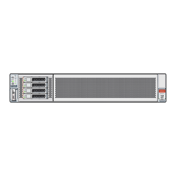
Page 12: About Exadata Server X10M
About Exadata Server X10M This section includes the server component overview. The Exadata Server X10M is a (1) or (2) processor socket, AMD® EPYC E5 Genoa™ SP5 processor-based, 2U rackmount server. The X10M is available with either a 4-Drive backplane [1] that supports up to four high performance NVMe drives or a 12-Drive backplane [2] that supports up to twelve high capacity SAS-3 drives. - Page 13 Up to four 2.5-inch hot-pluggable PCIe Gen4 NVMe SSDs: Oracle 13.6 TB (15.36 TB Max) TB 2.5-inch NVMe PCIe 4.0 SSD Oracle max 7.68 TB (15.36 TB Max) v2 2.5-inch NVMe PCIe 4.0 SSD Oracle max 3.84 TB (15.36 TB Max) v2 2.5-inch NVMe PCIe 4.0 SSD Up to four Oracle 30.72 TB QLC 2.5-inch NVMe PCIe 4.0 SSDs...
- Page 14 Two CEM Risers: Supports a single-wide PCIe CEM compliant PCIe card. PCIe cards • Up to eight Oracle Flash Accelerator F680 PCIe Cards: 6.8 TB, NVMe PCIe 4.0 • Up to three Oracle Dual Port QSFP56 Bifurcated 2x50Gb Network Interface Cards (NICs) •...
-
Page 15: Front Panel Components
If you are managing multiple servers, you can use Oracle Enterprise Manager Ops Center. For Oracle Enterprise Manager Ops Center 12c Release information about Ops Center, refer to Connected to x2 PCIe Gen5 links for boot drives. - Page 16 Chapter 1 Front Panel Components Callout Description Front LED Indicator Module (FIM) Storage drive 0 NVMe Storage drive 1 NVMe Storage drive 2 NVMe Storage drive 3 NVMe Service Information QR Code SAS Storage Drive Configuration Exadata Server X10M supports up to twelve 3.5-inch hot-pluggable SAS-3 hard disk drives (HDDs) on the front panel.
- Page 17 Chapter 1 Front Panel Components Callout Description Storage drive 10 SAS HDD Storage drive 11 SAS HDD Service Information QR Code Front LED Indicator Module Exadata Server X10M NVMe Storage Drive and SAS Storage Drive configurations support a Front LED status indicator module (FIM) on the front panel. Callout Description Front LED Indicator Module (FIM)
-
Page 18: Back Panel Components
Power Supply (PS0) status indicators: Fault-Service Required LED: amber; AC OK LED: green Power Supply (PS0) AC Power Inlet (AC0) (Oracle internal use only) Dedicated Root-of-Trust (RoT) card slot PCIe slot 1 (PCIe5, x16 electrical interface) PCIe slot 2 (PCIe5, x16 electrical interface) - Page 19 Processor. SP: Reset service processor (SP). See NET 0: Network (NET) 1GbE 100/1000BASE-T RJ-45 Gigabit Ethernet (GbE) port NET MGT: Oracle Integrated Lights Out Manager (ILOM) service processor (SP) network management (NET MGT) 1GbE RJ-45 100/1000BASE-T port USB 3.1 connector System status LEDs SYSTEM: Fault-Service Required: amber;...
-
Page 20: Illustrated Parts Breakdown
SP: Reset service processor (SP). See Processor. NET 0: Network (NET) 1GbE 100/1000BASE-T RJ-45 Gigabit Ethernet (GbE) port NET MGT: Oracle Integrated Lights Out Manager (ILOM) service processor (SP) network management (NET MGT) 1GbE RJ-45 100/1000BASE-T port USB 3.1 connector System status SYSTEM: Fault-Service Required: amber;... - Page 21 Chapter 1 Illustrated Parts Breakdown Callout Description Storage drives, up to four 2.5-inch hot-pluggable PCIe-based NVMe SFF SSDs in 4- Drive backplane Storage drive bay cage 4-Drive backplane (DBP) System chassis Front LED indicator module (FIM) Six fan modules (FM0-5) Fan tray Motherboard assembly (MB) Processors (P0, P1) and heatsinks (Single-processor systems contain only a single...
- Page 22 Air baffle System RTC battery Two power supplies (PS0, PS1) (Optional) Oracle RoT card (Optional) Nine HHHL PCIe cards PCIe slots 1 through 4 are nonfunctional in single-processor systems. (Optional) Two PCIe Risers (2 and 6) for FHFL PCIe cards...
-
Page 23: Replaceable Components
Top cover Air baffle System RTC battery PCIe card shroud (9-slot PCIe card back panel) (Optional) Oracle RoT card Nine HHHL PCIe cards PCIe slots 1 through 4 are nonfunctional in single-processor systems. Two power supplies (PS0, PS1) Replaceable Components This table lists server replaceable components and provides associated links to service replacement instructions. - Page 24 Provides SAS-3 signals between card located in PCIe slots and the disk backplane. Cold service Oracle Flash Accelerator F680 PCIe Card: 6.8 TB, NVMe PCIe 4.0 in Exadata Database Server X10M, Exadata Storage Server X10M, and Exadata Control Plane Server X10M 1-13...
-
Page 25: Troubleshooting And Diagnostics
When a server hardware fault event occurs, the system lights the Fault-Service Required LED and captures the event in the Oracle ILOM event log. If you set up notifications through Oracle ILOM, you also receive an alert through the notification method you choose. When you become aware of a hardware fault, address it immediately. -
Page 26: Troubleshoot Hardware Faults Using Oracle Ilom Cli
Service. Clear the fault in Oracle ILOM. Depending on the component, you might need to clear the fault in Oracle ILOM. Generally, components that have a FRU ID, clear the fault automatically. For details, refer to Oracle Integrated Lights Out Manager (ILOM) documentation at Oracle ILOM Documentation. -
Page 27: Troubleshoot Hardware Faults Using Oracle Ilom Web Interface
Oracle KnowledgeBase article. To prepare the server for service, see Preparing for Service. Service the component. After servicing the component, you might need to clear the fault in Oracle ILOM. For more information, refer the service procedures for the component. See Monitoring... - Page 28 Note: This procedure provides one basic approach to troubleshooting hardware faults. It uses the Oracle ILOM web interface. However, you can perform the procedure using the Oracle ILOM command-line interface (CLI). For more information about the Oracle ILOM web interface and CLI, refer to...
-
Page 29: Troubleshoot Power Issues
Prepare the server for service. After servicing the component, you might need to clear the fault in Oracle ILOM. For more information, refer to the service procedure for the component. For details, refer to Oracle Integrated Lights Out Manager (ILOM) documentation at Oracle ILOM Documentation. - Page 30 Chapter 2 Diagnosing Server Component Hardware Faults Table 2-1 Server Power Issues Power Description Action Prevention Issue AC Power The AC power cords are the direct Verify that both AC power Use the AC power cord Connection connection between the server power cords are connected to the Velcro retaining clips and supplies and the power sources.
-
Page 31: Troubleshoot System Cooling Issues
Chapter 2 Diagnosing Server Component Hardware Faults Troubleshoot System Cooling Issues Maintaining the proper internal operating temperature of the server is crucial to the health of the server. To prevent server shutdown and damage to components, you need to address overtemperature and hardware-related issues as soon as they occur. -
Page 32: Troubleshoot With Diagnostic Tools
After you determine the tool to use, you can access it locally, while at the server, or remotely. The selection of diagnostic tools available for your server range in complexity from a comprehensive validation test suite (Oracle VTS) to a chronological event log (Oracle ILOM event Log). The selection of diagnostic tools also includes standalone software packages, firmware-based tests, and hardware-based LED indicators. -
Page 33: Diagnostic Tool Selection
Diagnostics, and bridge integrated Console Plus. Applications circuits. Documentation UEFI SP firmware Tests and detects Use either the Oracle ILOM web Remote access Diagnostics problems on all interface or the command-line through Oracle processors, interface (CLI) to run UEFI ILOM Remote... -
Page 34: Attaching Devices To The Server
Note: The serial management port does not support network connections. Attach Ethernet access to the SP through a dedicated management port (NET MGT). To connect to the Oracle ILOM service processor over the network remotely, connect an Ethernet cable to the Ethernet port labeled MGT. -
Page 35: Configuring Serial Port Sharing
By default, the service processor (SP) controls the serial management (SER MGT) port and uses it to redirect the host serial console output. Using Oracle ILOM, you can assign the host console (COM1) as owner of the SER MGT port output, which allows the host console to output information directly to the SER MGT port. -
Page 36: Ethernet Device Naming
Connect a serial host to the server. Oracle ILOM web interface Log in to the SP Oracle ILOM web interface. Open a web browser and direct it using the IP address of the server SP. Log in as root or a user with administrator privileges. -
Page 37: Mac Address Mapping To Ethernet Ports
Chapter 2 Attaching Devices to the Server Table 2-4 Ethernet Device Naming Ethernet Oracle Linux 8 Oracle Solaris Windows (example default name, see Port and 9 note below) Net 0 eno1 igb0 Ethernet MAC Address Mapping to Ethernet Ports A system serial label that displays the MAC ID (and the associated barcode) for the server is attached to the top, front left side of the Exadata Server X10M server disk cage bezel. -
Page 38: Network Management Port
The serial management connector, labeled SER MGT, is an RJ-45 connector that can be accessed from the back panel. This port is the default connection to the server Oracle ILOM SP. Use only the SER MGT port for server management. Refer to Oracle ILOM Documentation. -
Page 39: Serial Management Port Signals
Chapter 2 Attaching Devices to the Server Table 2-7 Serial Management Port Signals Signal Description Signal Description Request to Send Ground Data Terminal Ready Receive Data Transmit Data Data Set Ready Ground Clear to Send Table 2-8 Default Serial Connections for Serial Port Parameter Setting Connector... -
Page 40: Usb Port
Chapter 2 Attaching Devices to the Server Table 2-9 (Cont.) RJ-45 to DB-9 Adapter Crossovers Wiring Reference Serial Port (RJ-45 Serial Port (RJ-45 DB-25 DB-25 Adapter Signal Connector) Pin Connector) Signal Adapter Pin Description Description Table 2-10 RJ-45 to DB-25 Adapter Crossovers Wiring Reference Serial Port (RJ-45 Serial Port (RJ-45 DB-25... -
Page 41: Accessing Oracle Ilom
Chapter 2 Accessing Oracle ILOM If the Oracle ILOM SP stops running and you cannot reset it using the Oracle ILOM web interface or the Oracle ILOM CLI, use the following procedure to reset the SP from the server back panel. - Page 42 Oracle ILOM Documentation Prerequisites: You need to know the IP address or host name of the service processor (SP) to log in to Oracle ILOM CLI or web interface remotely using one of the network ports on the server. Note: To enable first time login and access to Oracle ILOM, a default Administrator account and its password are provided with the system.
- Page 43 If the serial console is in use, stop and restart it using the stop /HOST/ console command followed by the start /HOST/console command. To return to the Oracle ILOM console, press Esc and then press Shift 9 to enter the open parenthesis ( character.
-
Page 44: Service Processor Connection And Login
Standby power is required for SP access, Main power and a running host is not required. Access Oracle ILOM. If this is the first time you are connecting to Oracle ILOM, do one of the following: • Access Oracle ILOM using a local serial connection to the command-line... -
Page 45: Test The Ipv4 Or Ipv6 Network Configuration
Oracle ILOM Documentation. Test the IPv4 or IPv6 Network Configuration • Use either the Oracle ILOM CLI or web interface to test the IPv4 or IPv6 network configuration. • From the Oracle ILOM CLI: At the CLI prompt, type the show command to view the network test targets and properties. - Page 46 IPv6 address. For example: ress ping6=2001::db8:5dff:febe:5000 Ping of 2001::db8:5dff:febe:5000 succeeded • From the Oracle ILOM web interface: Click ILOM Administration → Connectivity → Network. On the Connectivity page, click the Tools button. The Network Tools dialog box appears. 2-22...
-
Page 47: Set The Mouse Mode
Test. Set the Mouse Mode In Oracle ILOM, you can set the Mouse Mode property to optimize mouse movement in the Oracle ILOM Remote System Console Plus. The mouse mode can be set to either Absolute or Relative and must be set according to the requirements of the operating system that you are using to connect to Oracle ILOM. -
Page 48: Reset The Server Using Oracle Ilom
For more details, see Controlling System Power Oracle ILOM Documentation. Log in to the Oracle ILOM web interface or command-line interface (CLI) using an account with admin (a) role privileges. Reset the server: • From Oracle ILOM CLI, type: -> reset /System. When prompted, type y... -
Page 49: Monitoring Component Health And Faults Using Oracle Ilom
Chapter 2 Monitoring Component Health and Faults Using Oracle ILOM • Oracle ILOM web interface – Click the Log Out button in the top-right corner of the screen. Monitoring Component Health and Faults Using Oracle ILOM Oracle ILOM interfaces provide easy-to-view information about the health status of system components. -
Page 50: Contacting Support
Getting Help Contacting Support My Oracle Support If the troubleshooting procedures in this chapter do not solve your problem, use the following table to collect information that you might need to communicate to Oracle Support. Table 2-12 System Configuration Information... -
Page 51: Auto Service Requests
Oracle Auto Service Requests (ASR) is available at no additional cost to customers with Oracle Premier Support. Oracle ASR is the fastest way to restore system availability if a hardware fault occurs. Oracle ASR software is secure and customer installable, with the... -
Page 52: Preparing For Service
• Follow all standard cautions, warnings, and instructions marked on the equipment and described in the Oracle Server Safety and Compliance Guide and Important Safety Information for Oracle's Hardware Systems. • Ensure that the voltage and frequency of your power source match the voltage and frequency that appear on the equipment electrical rating label. -
Page 53: Electrostatic Discharge Safety
Disposable ESD mat (shipped with some replacement parts or optional system components) FRU Key Identity Properties (KIP) Automated Update Oracle ILOM includes a key identity properties (KIP) auto-update feature that ensures product information that is used for service entitlement and warranty coverage is... -
Page 54: Required Service Tools
Power supply (PS), designated as a backup quorum member. When a server FRU that contains the KIP is removed and a replacement component is installed, the KIP of the replacement component is programmed by Oracle ILOM to contain the same KIP as the other two components. -
Page 55: Powering Down The Server
Notify affected users that the server will be powered down. Save any open files, and quit all running applications. Refer to your application documentation for specific information about these processes. Log in to the Oracle ILOM command-line interface (CLI) using an Administrator account. Accessing Oracle ILOM. -
Page 56: Power Down The Server Gracefully Using Oracle Ilom Web Interface
Disconnect Cables From the Server. Caution: When you power down the server using Oracle ILOM, the server enters Standby power mode. Power is still directed to the service processor remote management subsystem and power supply fans. To completely power off the server, you must disconnect the power cords from the power supplies. -
Page 57: Power Down The Server For Immediate Shutdown Using Oracle Ilom Cli
An immediate power-off might corrupt system data, therefore, use this procedure to power down the server only after attempting the graceful power down procedure. Log in to the Oracle ILOM command-line interface (CLI) using an Administrator account. Accessing Oracle ILOM. -
Page 58: Power Down The Server For Immediate Shutdown Using Oracle Ilom Web Interface
Chapter 3 Preparing the Server for Component Replacement Power Down the Server for Immediate Shutdown Using Oracle ILOM Web Interface Caution: An immediate power-off might corrupt system data, therefore, use this procedure to power down the server only after attempting the graceful power down procedure. -
Page 59: Disconnect Cables From The Server
Chapter 3 Preparing the Server for Component Replacement Caution: When you power down the server using the On/Standby button, the server enters Standby power mode. Power is still directed to the service processor and power supply fans. To completely power off the server, you must disconnect the power cords from the power supplies. -
Page 60: Remove The Server From The Rack
To prevent the rack from tipping forward when the server is extended, extend all rack anti-tilt mechanisms. Stabilize the Rack. Also refer to the Oracle Rack Cabinet 1242 User's Guide at Oracle Rack Cabinet 1242 Documentation Library. Verify that no cables will be damaged or will interfere when the server is extended. -
Page 61: Take Antistatic Measures
You can use the following items as an antistatic mat: • Antistatic bag used to wrap a replacement part • Oracle ESD mat (orderable item) • Disposable ESD mat (shipped with some replacement parts or optional system components) Attach an antistatic wrist strap. -
Page 62: Remove The Server Top Cover
Chapter 3 Preparing the Server for Component Replacement When servicing or removing server components, attach an antistatic strap to your wrist and then to a metal area on the chassis. Then perform procedures for servicing the server. Note: An antistatic wrist strap is not included in the Accessory Kit for the server. However, antistatic wrist straps might be included with options and components. - Page 63 Chapter 3 Preparing the Server for Component Replacement Lift up and remove the top cover [2]. 3-12...
-
Page 64: Servicing Storage Drives
Servicing Storage Drives This section describes how to service storage drives. Storage drives are replaceable components that do not require you to power off the server before servicing. For more information about replaceable components, see Illustrated Parts Breakdown Replaceable Components. Note: The procedures and illustrations in this chapter apply to both NVMe and SAS storage drives, except where noted. -
Page 65: Remove A Storage Drive
Chapter 4 Remove a Storage Drive a new storage drive is inserted, the contents are automatically rebuilt from the rest of the array with no need to reconfigure the RAID parameters. If you configured the replaced storage drive as a hot-spare, the new HDD is automatically configured as a new hot-spare. - Page 66 Chapter 4 Remove a Storage Drive Note: NVMe storage drives are supported only on servers that are running Oracle Linux, Oracle Solaris, or Microsoft Windows Server. – Removing and Replacing an NVMe Storage Drive Using Oracle Solaris – Removing and Replacing an NVMe Storage Drive Using Oracle Linux –...
-
Page 67: Install A Storage Drive
Chapter 4 Install a Storage Drive Consider your next steps: • If you are replacing the drive, continue to Install a Storage Drive. • If you are not replacing the drive, install a filler in the empty drive slot to maintain proper airflow and perform administrative tasks to configure the server to operate without the drive. -
Page 68: Removing And Replacing Storage Drives Using An Os
Oracle Linux operating system. Unmount an NVMe Storage Drive Log in to Oracle Linux that is running on the server. Remove the NVMe storage device path. To find the PCIe addresses (Bus Device Function), type:... -
Page 69: Remove An Nvme Storage Drive
Chapter 4 Removing and Replacing Storage Drives Using an OS /sys/devices/ pci0000:d7/0000:d7:02.0/0000:e3:00.0/0000:e4:07.0/0000:e8:00.0/nvme/ nvme10/cntlid To obtain the slot number (APIC ID) for the bus address, type the following command to list the PCIe slot numbers with corresponding bus addresses: # egrep -H ‘.*’ /sys/bus/pci/slots/*/address This commands returns output similar to the following example, with the bus addresses for the corresponding NVMe instances in bold text. -
Page 70: Verify Removal Of An Nvme Storage Drive
Chapter 4 Removing and Replacing Storage Drives Using an OS For storage drive locations, see NVMe Storage Drives. Verify that the OK to Remove indicator (LED) on the NVMe drive is lit. On the NVMe drive you plan to remove, push the latch release button to open the drive latch. -
Page 71: Power On An Nvme Storage Drive And Attach A Device Driver
Chapter 4 Removing and Replacing Storage Drives Using an OS Close the drive latch to lock the drive in place. Power On an NVMe Storage Drive and Attach a Device Driver • To power on the slot and attach the device driver, type: # echo 1 >... -
Page 72: Servicing Power Supplies
Servicing Power Supplies This section describes how to service power supplies. Power supplies are replaceable components that do not require you to power off the server before servicing. For more information about replaceable components, see Illustrated Parts Breakdown Replaceable Components. The power supplies are located at the back of the server. -
Page 73: Remove A Power Supply
You also can use the Oracle ILOM show faulty command at the Oracle ILOM command-line prompt (->) to identify a power supply failure. To list all known faults in the server, log in to the Oracle ILOM Fault Management Shell from the Oracle ILOM service processor and issue the fmadm faulty command. -
Page 74: Install A Power Supply
Chapter 5 Install a Power Supply Disconnect the power cord from the failed power supply. Grasp the power supply handle and push the power supply latch to the left. Open the power supply handle if the handle is folded flush. Open the velcro straps if present. - Page 75 Fault-Service Required LEDs are not lit on the front and back panels. Note: After you replace Power Supply 0, you must reset the Oracle ILOM service processor (SP) to propagate the key identity properties (KIP) data to the new power supply. For instructions on resetting the SP, refer...
-
Page 76: Servicing Fan Modules
Oracle ILOM. Even if only one fan motor is faulted within the fan module, the Oracle ILOM service processor detects that two fan motors have failed to spin while the fan module is removed. -
Page 77: Install A Fan Module
Chapter 6 Install a Fan Module LED Color and State Meaning Amber – The fan module is faulty. The front Top Fan LED and the front and back panel Fault-Service Required LEDs are also lit if the system detects a fan module fault. Using your forefinger and thumb, lift the fan module straight up and out of the chassis and set it aside on an antistatic mat. -
Page 78: Remove The Fan Tray
Chapter 6 Remove the Fan Tray With the server top cover removed, install the replacement fan module into the server. The fan modules are keyed to ensure that they are installed in the correct orientation. Press down on the fan module to fully seat the fan module. Verify that the fan module status indicator (LED) for the replacement fan module is not illuminated. - Page 79 Chapter 6 Remove the Fan Tray When removing the fan tray, slightly tilt the fan tray to the left to decompress the cables, before the operation. Ensure all motherboard cables are clear of the fan tray and fan tray gasket. Lift the fan tray from the server.
-
Page 80: Install The Fan Tray
Chapter 6 Install the Fan Tray Continue with the next step in the service procedure. Install the Fan Tray Perform this procedure only when servicing Disk backplane, SAS cables, and Motherboard assembly replaceable components: Lower the fan tray into the server. Ensure all motherboard cables are clear of the fan tray and fan tray gasket. - Page 81 Chapter 6 Install the Fan Tray Install the fan modules into the fan tray. Install a Fan Module. Install the air baffle. Install the Air Baffle Continue with the next step in the service procedure.
-
Page 82: Servicing Internal M.2 Flash Ssds
Servicing Internal M.2 Flash SSDs This section describes how to service M.2 flash solid-state drives (SSDs). M.2 flash SSDs are replaceable components that do not require you to power off the server before servicing. For more information about replaceable components, see Illustrated Parts Breakdown Replaceable... -
Page 83: Install A Flash Riser Board
Chapter 7 Install a Flash Riser Board Rotate both riser board socket levers outward as far as they go. Note: The green Power LED indicator located on the riser board is extinguished when you open the socket levers. Carefully lift the riser board straight up to remove it from the sockets. Place the riser board on an antistatic mat. -
Page 84: Identify And Remove An M.2 Flash Ssd
Chapter 7 Identify and Remove an M.2 Flash SSD Caution: If the riser board does not easily seat into the connector socket, verify that the notch in the riser board is aligned with the connector key in the connector socket. If the notch is not aligned, damage to the riser board might occur. - Page 85 Chapter 7 Identify and Remove an M.2 Flash SSD Using the Server Fault Remind Button. Failed SSDs are identified with a corresponding amber LED that is lit on the flash riser board. • If the SSD fault LED is off, then the SSD is operating properly. •...
-
Page 86: Install An M.2 Flash Ssd
Chapter 7 Install an M.2 Flash SSD Remove the plastic retainer clip from the M.2 flash SSD [1]. Lift up on the end of the M.2 flash SSD where the plastic retainer clip was removed by one-half to one inch [2]. Gently slide the M.2 flash SSD card back and out of the connector to disengage the SSD contacts from the riser board socket [2]. -
Page 87: Servicing The Air Baffle
Servicing the Air Baffle This section describes how to service the air baffle. You must power off the server before servicing the air baffle. The air baffle must be in place during system operation. Remove the air baffle to lift the Motherboard and access the motherboard handle. -
Page 88: Install The Air Baffle
Chapter 8 Install the Air Baffle Set aside the air baffle. Consider your next step: • If you removed the air baffle as part of another procedure, return to that procedure. • Otherwise, continue to Install the Air Baffle. Install the Air Baffle Install the air baffle by placing it into the server and lowering it to its inserted position. - Page 89 Chapter 8 Install the Air Baffle each side is under the lip of the fan tray, and the others are on top of the fan tray. Consider your next step: • If you removed the air baffle as part of another procedure, return to that procedure. •...
-
Page 90: Servicing Dimms
Servicing DIMMs This section describes how to service dual in-line memory modules (DIMMs). DIMMs are replaceable components that require you to power off the server before servicing. For more information about replaceable components, see Illustrated Parts Breakdown Replaceable Components. Caution: These procedures require that you handle components that are sensitive to electrostatic discharge. -
Page 91: Dimm Population Scenarios
Chapter 9 DIMM Population Scenarios Each processor, P0 and P1, has twelve DIMM slots (D0-D11), six on each processor side. Each DIMM slot supports a single memory channel, for total of twelve DDR5 memory channels per processor (0-11). Table 9-1 Memory Channels and DIMM Slots for P0 and P1 Memory Channel DIMM Slot... -
Page 92: Dimm Population Rules
Chapter 9 DIMM Population Rules In this scenario, you can use the Fault Remind button to determine the failed DIMM, and then remove the failed DIMM and replace it. To ensure that system performance is maintained, you must replace the failed DIMM with a DIMM of the same size (in gigabytes) and type (quad-rank or dual-rank). -
Page 93: Populating Dimms For Optimal System Performance
Chapter 9 Populating DIMMs for Optimal System Performance Populating DIMMs for Optimal System Performance Optimal performance is generally achieved by populating the DIMMs so that the memory is symmetrical, or balanced. Symmetry is achieved by adhering to the following guidelines: •... - Page 94 Chapter 9 Populating DIMMs for Optimal System Performance Populating DIMMs in Dual-Processor Systems for Optimal System Performance In dual-processor systems, install DIMMs into DIMM slots starting with processor 0 (P0) D5, alternating between slots associated with processor 0 (P0) and matching slots for processor 1 (P1).
-
Page 95: Using The Server Fault Remind Button
Chapter 9 Using the Server Fault Remind Button P0/D6 P0/D3 P0/D8 P0/D4 P0/D7 P0/D1 P0/D10 P0/D2 P0/D9 P0/D0 P0/D11 Using the Server Fault Remind Button When you press the server Fault Remind button [1], an LED located next to the Fault Remind button lights green which indicates that there is sufficient voltage present in the fault remind circuit to light any fault LEDs that were lit due to a component failure. - Page 96 Chapter 9 Identify and Remove a DIMM Powering Down the Server. Disconnect the power cords from the power supplies. Disconnect Cables From the Server. Extend the server into the maintenance position. Extend the Server to the Maintenance Position. Attach an antistatic wrist strap to your wrist and then to a metal area on the chassis. Take Antistatic Measures.
-
Page 97: Install A Dimm
Chapter 9 Install a DIMM Replace each failed DIMM with either another DIMM of the same rank size (quad- rank or dual-rank) or leave the slot empty. For DIMM replacement instructions, see Install a DIMM. Install a DIMM Unpack the replacement DIMM and place it on an antistatic mat. Ensure that the replacement DIMM matches the size, type, and rank of the DIMM it is replacing. - Page 98 Server. Verify that the power supply AC OK LED is lit. (Optional) Use Oracle ILOM to clear server DIMM faults. DIMM faults are automatically cleared after a new DIMM has been installed. If you need to manually clear DIMM faults, refer to Oracle ILOM Documentation.
-
Page 99: Servicing The Battery
Servicing the Battery This section describes how to service the system battery. The system battery is a replaceable component that requires you to power off the server before servicing. For more information about replaceable components, see Illustrated Parts Breakdown Replaceable Components. - Page 100 Chapter 10 Remove the Battery Note: Coin battery retainer types that are mounted in the RTC battery motherboard location may be different. Remove the battery from the battery holder. Review the following battery holder (Part number: 8210501) options. Callout Description 796136-1 Top-Load Battery Connector (TE) 1093TR Top-Load Battery Connector 1070TR Top-Load Battery Connector...
- Page 101 Chapter 10 Remove the Battery positive contact. The connector features four lips for positive retention of the battery. Grasp connector. Support the connector by grasping the "positive" end of the connector. Note: CAUTION! The connector must be supported, otherwise damage to the soldered contacts could occur.
-
Page 102: Install The Battery
Chapter 10 Install the Battery Install the Battery Unpack the replacement RTC battery. Press the new battery into the battery retainer. • Install the battery into the Top-Load Battery Connector as follows: Each connector consists of a housing with a positive contact and a negative contact. - Page 103 Chapter 10 Install the Battery Note: Insert the battery so that the positive (+) side is facing up. • Press the new battery into the battery retainer with the positive side (+) facing up. 10-5...
- Page 104 Otherwise, proceed to the next step. If the service processor is not configured to use NTP, you must do one of the following: • Reset the Oracle ILOM clock using Oracle ILOM CLI or web interface. Refer to Oracle ILOM Documentation. •...
-
Page 105: Servicing Pcie Cards
Servicing PCIe Cards This section describes how to service PCIe cards and PCIe Risers. PCIe cards and PCIe risers are replaceable components that require you to power off the server before servicing. For more information about replaceable components, see Illustrated Parts Breakdown Customer-Replaceable Units. -
Page 106: Remove A Half Height Pcie Card
Chapter 11 Remove a Half Height PCIe Card • The Full Height card chassis configuration uses two PCIe riser cards supporting two Full height 10.5 inch double width GPU cards at x16 PCIe Gen4. • Each riser also supports a PCIe Gen3 Pensando Ortano/Elba Server Adapter, DSC-200V, 2x200GbE, Dual QSFP56 Smart NIC card. -
Page 107: Install A Half Height Pcie Card
Chapter 11 Install a Half Height PCIe Card Place the PCIe card on an antistatic mat. Caution: If you are not immediately inserting a replacement PCIe card into the empty slot, insert a PCIe filler panel in the slot to reduce the possibility of radiated electromagnetic interference (EMI). - Page 108 Chapter 11 Install a Half Height PCIe Card PCIe slots 1 through 4 are nonfunctional in single-processor systems. See Back Panel Components. If necessary, remove the PCIe filler panel from the slot. Save this filler panel in case you need to remove the PCIe card from the system. Insert the PCIe card into the correct slot [1], and rotate the PCIe locking mechanism downward to secure the PCIe card in place [2].
-
Page 109: Remove A Full Height Pcie Card
Use Oracle ILOM to clear any server PCIe card faults. If a PCIe card fault message in Oracle ILOM is not cleared under Open Problems, you must manually clear the fault using Oracle ILOM. refer to "Clear Faults for Undetected Replaced or Repaired Hardware Components"... - Page 110 Chapter 11 Remove a Full Height PCIe Card While holding the PCIe Riser in one hand, use your other hand to carefully pull the PCIe card connector out of the PCIe Riser slot. If required, unplug any data cables from the PCIe card. Note the cable connections so that it's easier to properly reconnect the cables.
-
Page 111: Install A Full Height Pcie Card
Chapter 11 Install a Full Height PCIe Card Install a Full Height PCIe Card This task also applies to half-height PCIe cards that are being installed in PCIe Risers. If you are installing a x16 PCIe card in Riser 6, you must install the motherboard PCIe Flyover cable in to slot 6 to enable support for a PCIe x16 electrical interface;... -
Page 112: Remove A Pcie Riser
Chapter 11 Remove a PCIe Riser Reconnect the cables to the PCIe card that you unplugged during the removal procedure. If it is difficult to reconnect the cables to the PCIe card when the card is secured into the PCIe slot, consider performing this procedure prior to inserting the PCIe card in to the PCIe Riser slot. - Page 113 Chapter 11 Remove a PCIe Riser Remove the server top cover. Remove the Server Top Cover. Identify the proper back panel PCIe slot (Riser 2 or Riser 6) for the Riser you are replacing. See Full Height PCIe Configuration in Back Panel Components.
-
Page 114: Install A Pcie Riser
Chapter 11 Install a PCIe Riser Leave the PCIe data and power cables attached to the PCIe card and place the PCIe card on an antistatic mat. You will need to install the PCIe card in the replacement PCIe riser. See also Remove a Full Height PCIe Card Remove a Half Height PCIe... - Page 115 Chapter 11 Install a PCIe Riser Using a Torx (6 lobe) T25 screwdriver, tighten two captive screws to 8 in-lb (0.9 Nm/9.2 kg-cm) to secure the PCIe riser to the motherboard [2] and the rear panel of the server [3]. Reconnect the PCIe Riser signal cable between the motherboard and PCIe riser [4].
-
Page 116: Configure Pcie Electrical Interfaces Using The Pcie Flyover Cable
Configure PCIe Electrical Interfaces Using the PCIe Flyover Cable Use Oracle ILOM to clear any server PCIe card faults. If a PCIe card fault message in Oracle ILOM is not cleared under Open Problems, you must manually clear the fault using Oracle ILOM. refer to "Clear Faults for Undetected Replaced or Repaired Hardware Components"... -
Page 117: Remove The Pcie Flyover Cable
Chapter 11 Remove the PCIe Flyover Cable Callout Description PCIe Flyover cable PCIe slot 7 electrical interface connector PCIe slot 6 electrical interface connector Install the connector in the desired slot and press down on the connector until it is fully seated in the slot [2]. -
Page 118: Install The Pcie Flyover Cable
Chapter 11 Install the PCIe Flyover Cable Disconnect Cables From the Server. Extend the server to the maintenance position. Extend the Server to the Maintenance Position. Attach an antistatic wrist strap. Take Antistatic Measures. Remove the server top cover. Remove the Server Top Cover. - Page 119 Chapter 11 Install the PCIe Flyover Cable Plug each end of the cable into its connector until you hear an audible click. If necessary, reinstall PCI Riser 6. Install a PCIe Riser. Return the server to operation. Install the top cover. Install the Server Top Cover.
-
Page 120: Servicing The Motherboard Assembly
See Electrostatic Discharge Safety. Remove the Motherboard Assembly Caution: Use the Oracle ILOM backup utility prior to removing the motherboard. This utility backs up the Oracle ILOM configuration of the service processor. Refer to Oracle ILOM Documentation. Prepare the server for service. - Page 121 (KIP) data might be lost. When a server requires service, the KIP is used by Oracle to verify that the warranty on the server has not expired. For more information on KIP, FRU Key Identity Properties (KIP) Automated Update.
- Page 122 Chapter 12 Remove the Motherboard Assembly Front LED indicator module (FIM) ribbon cable Servicing the Front LED Indicator Module. Disk backplane auxiliary signal (DBP SIG) cable Servicing the Disk Backplane. Disk backplane power (DBP PWR) cable Disconnect the power cable from the motherboard and the disk backplane connections.
- Page 123 Chapter 12 Remove the Motherboard Assembly Using a Torx T25 screwdriver, fully loosen the two captive screws that secure the motherboard mid-wall to the chassis. If you are not able to remove the motherboard, loosen the third screw in the midwall motherboard handle.
- Page 124 Chapter 12 Remove the Motherboard Assembly Place the motherboard assembly on an antistatic mat, and next to the replacement motherboard. Remove the following reusable components from the old motherboard and install them onto the replacement motherboard. • DIMMs Identify and Remove a DIMM Install a DIMM.
- Page 125 Chapter 12 Remove the Motherboard Assembly Note the orientation and correct handling of the External Cap. Callout Description Top of External Cap (insertion tabs are circled) Bottom of External Cap (contacts the socket) Use of the External Cap handle Processor Overview for processor frame and socket information.
- Page 126 Chapter 12 Remove the Motherboard Assembly Lift the force frame to the open position. On the socket, open the Rail Frame. Squeeze the blue tabs to release the rail frame. 12-7...
- Page 127 Chapter 12 Remove the Motherboard Assembly Lift the processor rail frame by holding its lift tabs and rotating the rail frame to its near vertical position. Note: The rail frame is spring-loaded. Hold on to the rail frame as it releases from the socket frame, when rotating it to the vertical position.
- Page 128 Chapter 12 Remove the Motherboard Assembly Retain the external cap to be placed on the processor socket (in the Rail Frame) of the motherboard being replaced. This will prevent damage during shipping back to the Service Center for motherboard failure analysis. Install an External Cap on a P0 or P1 socket for motherboard returns.
- Page 129 Chapter 12 Remove the Motherboard Assembly Grasping the rail frame edge [1], rotate the rail frame to the closed position [2]. Rotate the force frame to its closed position on the socket stiffener frame. Using a 12 in-lb (inch-pound) (1.35 Nm/13.5 kg-cm) driver with a Torx T20 bit, fully tighten the captive screw that secures the force frame to the socket stiffener frame.
- Page 130 Chapter 12 Remove the Motherboard Assembly Use one hand to hold down the spring-loaded force frame until the screw is tightened. Install a processor into the socket on the replacement motherboard. Install a processor into the socket P0 or P1 from which you removed the processor External Cap.
-
Page 131: Install The Motherboard Assembly
Chapter 12 Install the Motherboard Assembly Twist the tool back and forth to release the light pipe from the housing. Pull the light pipe away from the housing. iii. Install the light pipe on the replacement motherboard. Match the rectangular holes on the outside of the light pipe with the retaining clips on the housing. - Page 132 Chapter 12 Install the Motherboard Assembly While holding the motherboard mid-wall handle and small plastic motherboard handle, tilt the motherboard to the right side to fit it under the power supply assembly, and level the motherboard and place it into the server chassis. Slide the motherboard to the back of the server to engage the raised standoffs.
- Page 133 Chapter 12 Install the Motherboard Assembly Disk backplane auxiliary signal (DBP SIG) cable Servicing the Disk Backplane. Front LED indicator module (FIM) ribbon cable Servicing the Front LED Indicator Module. Callout Description Disk backplane power (DBP PWR) cable Disk backplane auxiliary signal (DBP SIG) cable Front LED indicator module (FIM) ribbon cable Reinstall the following components: 12-14...
- Page 134 (KIP) data might be lost. When a server requires service, the KIP is used by Oracle to verify that the warranty on the server has not expired. For more information on KIP, see...
- Page 135 Chapter 12 Install the Motherboard Assembly Note: IMPORTANT: After replacing the motherboard, you might need to manually program the product serial number (PSN) into the new motherboard. This is necessary because the motherboard is a secondary member of a select group (or quorum) of components used for maintaining the PSN for service entitlement.
-
Page 136: Servicing Processors
Servicing Processors This section describes how to service processors. Processors are replaceable components that require you to power off the server before servicing. For more information about replaceable components, see Illustrated Parts Breakdown Replaceable Components. Caution: Ensure that all power is removed from the server before removing or installing a processor. - Page 137 Chapter 13 Processor Overview Callout Description Pin 1 orientation Force Frame Retention Screw (captive) Force Frame (retention frame) Release Tabs (2x) Rail Frame (socket stiffener frame) Processor Package (carrier frame holding preinstalled processor) Heatsink Attachment Studs (6x) External Cap The external cap is used to protect the socket pins if the processor is not installed. The following figure shows the External Cap.
-
Page 138: Identify And Remove A Processor
Chapter 13 Identify and Remove a Processor Identify and Remove a Processor • Use ESD gloves (not latex or vinyl), if possible, when handling the processor. • Obtain a torque driver set to 12 in-lb (inch-pound) (1.35 Nm/13.5 kg-cm) force with T20 Torx bit for processor and heatsink removal. - Page 139 Chapter 13 Identify and Remove a Processor • Never remove the processor from the carrier. Replacement processors come with a carrier package. • Whenever you remove a processor on a usable motherboard, replace it with another processor and reinstall the processor heatsink; otherwise, the server might overheat due to improper airflow.
- Page 140 Chapter 13 Identify and Remove a Processor Note: When you press the Fault Remind button, an LED located next to the Fault Remind button illuminates green, indicating that there is sufficient voltage in the fault remind circuit to illuminate any fault LEDs that were illuminated due to a failure.
- Page 141 Chapter 13 Identify and Remove a Processor Loosen in reverse order 6-1, then go back and disengage completely. Loosen captive screws 6,5,4,3,2,1 in the order shown in the illustration. Disengage captive screws 6,5,4,3,2,1 in the order shown in the illustration. Use a torque driver set to 12 in-lb (inch-pound) (1.35 Nm/13.5 kg-cm) force with T20 Torx bit.
- Page 142 Chapter 13 Identify and Remove a Processor Note: Always grip the heatsink along the axis of the fins to prevent damage. Place the heatsink, facing up, on a work surface. Remove Thermal Grease. Clean off the thermal interface material (TIM) using the supplied alcohol wipes. If reusing a processor, do not remove it from the processor carrier.
- Page 143 Chapter 13 Identify and Remove a Processor Caution: Failure to clean thermal grease from the heatsink could result in the accidental contamination of the processor socket or other components. Be careful not to get the grease on your fingers, as this could result in contamination of components.
- Page 144 Chapter 13 Identify and Remove a Processor Using a Torx T20 screwdriver, loosen the captive Force Frame Retention Screw that secures the Force Frame to the socket. Lift the Force Frame to the open position. Apply counter-pressure to the Force Frame when opening. Open the Rail Frame.
- Page 145 Chapter 13 Identify and Remove a Processor Squeeze the blue tabs to release the Rail Frame. Lift the Rail Frame and slide out the carrier frame package. Lift the Rail Frame by holding its lift tabs and rotating the Rail Frame to its near vertical position.
- Page 146 Chapter 13 Identify and Remove a Processor Place the carrier frame package in an appropriate tray. Wipe the Force Frame (retention frame) with a dry wipe followed by a wipe with a small amount of isopropyl alcohol. Clean off the thermal interface material (TIM) as needed, wipe the outside and inside of the Force Frame with a dry wipe followed by a wipe with a small amount of isopropyl alcohol.
-
Page 147: Install A Processor
Chapter 13 Install a Processor Wipe the processor lid and carrier frame with a dry wipe followed by a wipe with a small amount of isopropyl alcohol. Clean off the thermal interface material (TIM) from the processor using the supplied alcohol wipes. Install a Processor •... - Page 148 Chapter 13 Install a Processor Caution: The processor socket pins are very fragile. A light touch can bend the processor socket pins beyond repair. • If you are replacing a processor, ensure that the replacement processor is identical to the processor that was removed.
- Page 149 Chapter 13 Install a Processor Callout Description Bottom of processor carrier (contacts the socket) Use of the processor carrier handle Install the processor package by sliding it in the Rail Frame and pressing down. Holding the processor carrier by its handle, slide it into the Rail Frame, until the two insertion tabs at the bottom of the processor carrier are inserted into the slots in the Rail Frame.
- Page 150 Chapter 13 Install a Processor Rotate the Force Frame to its closed position on the socket stiffener frame. Using a 12 in-lb (inch-pound) (1.35 Nm/13.5 kg-cm) driver with a Torx T20 bit, fully tighten the captive screw that secures the Force Frame to the socket stiffener frame. Use one hand to hold down the spring-loaded Force Frame until the screw is tightened.
- Page 151 Chapter 13 Install a Processor Apply Thermal Grease. Using the supplied syringe, evenly apply all of thermal interface material (TIM) in an "S" pattern centered on the top of the processor. Keep the "S" pattern inside a half inch of the processor edge so the grease doesn't overflow and contaminate other parts of the processor housing.
- Page 152 Chapter 13 Install a Processor Note: The heatsink is keyed to go on only one way. The captive screws that attach to the pin 1 end of the socket stiffener frame are closer together than the captive screws that attach at the opposite end of the stiffener frame. Tighten captive screws 1, 2, 3, 4, 5 and 6 in the order shown.
- Page 153 Verify that the power supply AC OK LED is lit. Use Oracle ILOM to clear server processor faults. To show server faults: log in to the server as root using the Oracle ILOM CLI, and type the following command to list all known faults on the server: ->...
- Page 154 Are you sure you want to clear /SYS/MB/P0 (y/n)? Set ‘clear_fault_action’ to ‘true’ Alternatively, to clear all known faults in the server, log in to the Oracle ILOM service processor from the Oracle ILOM Fault Management Shell and issue the fmadm repair command.
-
Page 155: Servicing The Disk Backplane
Servicing the Disk Backplane This section describes how to service the 4-Drive backplane and 12-Drive backplane. The disk backplane (DBP) is a replaceable component that requires you to power off the server before servicing. Perform the 4-Drive backplane or 12-Drive backplane procedures. For more information about replaceable components, see Illustrated Parts Breakdown Replaceable... - Page 156 Chapter 14 Remove the 4-Drive Backplane Remove the fan modules from the server. Remove a Fan Module. Remove the fan tray from the server. Remove the Fan Tray. Remove all NVMe storage drives from the server front panel and set them aside on an antistatic mat.
-
Page 157: Install The 4-Drive Backplane
Chapter 14 Install the 4-Drive Backplane Disconnect the DBP power cable and the DBP auxiliary signal cable from the motherboard connectors, and remove the DBP auxiliary signal cable from the left- side cable trough [1]. Note: Do not disconnect the DBP power cable and DBP auxiliary signal cable from the disk backplane at this time. - Page 158 Chapter 14 Install the 4-Drive Backplane Reconnect the DBP power cable and the DBP auxiliary signal cable to the disk backplane [3]. Install the storage drive cage in to the chassis. Align the storage drive cage with the opening in the front panel of the server. Pull the attached DBP power cable and DBP auxiliary signal cable through the opening while gently pushing the storage drive cage in to the chassis until it is fully seated in the chassis [4].
-
Page 159: Remove The 12-Drive Backplane
Note: IMPORTANT: When the disk backplane is replaced, the key identity properties (KIP) of the backplane is programmed by Oracle ILOM to contain the same KIP as the other quorum member components. If you removed other quorum member components, you might need to manually program the product serial number (PSN) into the new backplane. - Page 160 Chapter 14 Remove the 12-Drive Backplane Remove the fan tray from the server. Remove the Fan Tray. Pull each storage drive out far enough to disengage it from the backplane. Remove a Storage Drive. Note: It is not necessary to completely remove the storage drives from the server;...
-
Page 161: Install The 12-Drive Backplane
Chapter 14 Install the 12-Drive Backplane Disconnect the DBP auxiliary signal cable from the 12-Drive backplane [3]. See also Remove the Disk Backplane Signal Cable. Using a Torx T15 screwdriver, loosen the right-side and left-side spring-mounted screws that secure the 12-Drive backplane to the chassis [4]. Lift the 12-Drive backplane up to release it from the standoff hooks and out of the chassis [5 and 6]. - Page 162 Chapter 14 Install the 12-Drive Backplane Using a Torx T15 screwdriver, tighten the right-side and left-side spring-mounted screws to secure the 12-Drive backplane to the chassis [3]. Reconnect the cables to the disk backplane. Reconnect the DBP auxiliary signal cable to the 12-Drive backplane [4]. See also Install the Disk Backplane Signal Cable.
-
Page 163: Remove The Disk Backplane Signal Cable
Note: IMPORTANT: When the disk backplane is replaced, the key identity properties (KIP) of the backplane is programmed by Oracle ILOM to contain the same KIP as the other quorum member components. If you removed other quorum member components, you might need to manually program the product serial number (PSN) into the new backplane. - Page 164 Chapter 14 Remove the Disk Backplane Signal Cable Remove the fan tray from the server. Remove the Fan Tray. Locate the disk backplane signal cable. The disk backplane signal cable is connected between the 4 or 12 disk backplane and the motherboard connector, which is located between PCIe slot 4 and the motherboard handle.
-
Page 165: Install The Disk Backplane Signal Cable
Chapter 14 Install the Disk Backplane Signal Cable Disconnect and remove the disk backplane signal cable from the server. Disconnect the signal cable from the disk backplane and the motherboard [1]. At each end of the signal cable, press and hold the connector to disengage the locking mechanism, then gently lift the connector from the disk backplane and motherboard. - Page 166 Chapter 14 Install the Disk Backplane Signal Cable Ensure that the disk backplane signal cable is free from snagging motherboard components and other cables in the server. You might need to remove the SAS cables from the left-side cable trough before installing the disk backplane signal cable.
- Page 167 Chapter 14 Install the Disk Backplane Signal Cable Note: For information on reconnecting the disk backplane signal cable to the 4-disk backplane, see Install the 4-Drive Backplane. If necessary, reinstall SAS cables in the left-side cable trough. Install SAS Storage Drive Cables.
-
Page 168: Servicing The Front Led Indicator Module
Servicing the Front LED Indicator Module This section describes how to service the front LED indicator module. The front LED indicator module is a replaceable component that requires you to power off the server before servicing. For more information about replaceable components, see Illustrated Parts Breakdown Replaceable... - Page 169 Chapter 15 Remove the Front LED Indicator Module Note: To ease removal of the LED indicator module cable, you might need to lift the disk backplane auxiliary signal cable and SAS cable (if present) from the left-side cable trough. Remove the three No. 2 Phillips screws that secure the FIM cable cover to the chassis [1].
-
Page 170: Install The Front Led Indicator Module
Chapter 15 Install the Front LED Indicator Module Remove the front LED indicator module [2]. Remove the two No. 2 Phillips screws that secure the LED indicator module to the server front panel. Remove the LED indicator module and cable from the server front panel. Remove the LED indicator module cable by carefully pulling the cable through the left-side cable trough. - Page 171 Chapter 15 Install the Front LED Indicator Module Insert and tighten the two No. 2 Phillips screws to secure the LED indicator module to the server front panel [1]. Install the FIM cable cover to the chassis by inserting it into the FIM cable cover slot [2].
-
Page 172: Servicing Sas Cables
Servicing SAS Cables This section describes how to service SAS cables. SAS interface cables are replaceable components that require you to power off the server before servicing. For more information about replaceable components, see Illustrated Parts Breakdown Replaceable Components. Caution: The system supplies power to the cables even when the server is powered off. -
Page 173: Install Sas Storage Drive Cables
Chapter 16 Install SAS Storage Drive Cables Remove the fan tray from the server. Remove the Fan Tray. Disconnect the SAS cables from the disk backplane [1]. Press and hold the button on the connector to disengage the locking mechanism, then gently pull the connector from the disk backplane. - Page 174 Chapter 16 Install SAS Storage Drive Cables Reconnect the SAS cables to the Broadcom 9500-16i, 12GB SAS PCIe, 16 Port, Internal card in PCIe slot 9 [2]. Plug each cable into its SAS connector until you hear an audible click. To ensure proper SAS cable connections, see the SAS cable connections table in Step Note:...
- Page 175 Chapter 16 Install SAS Storage Drive Cables Install a Fan Module. Install the air baffle. Install the Air Baffle. Install the server top cover. Install the Server Top Cover. Return the server to the normal rack position. Return the Server to the Normal Rack Position.
-
Page 176: Returning The Server To Operation
Returning the Server to Operation This section describes safety considerations and provides procedures and information after replacing components in the server. After replacing components inside of the server, perform the procedures in the following sections. Server Filler Panel Requirements The server might be shipped with module-replacement filler panels for storage drives and PCIe cards. -
Page 177: Install The Server Top Cover
Chapter 17 Install the Server Top Cover Remove the PCIe slot filler panel. Remove the server top cover. To remove the PCIe slot filler panel, rotate the PCIe locking mechanism in to an upright position, and lift and remove the PCIe slot filler panel where you want to install the PCIe card. -
Page 178: Remove Antistatic Measures
Chapter 17 Remove Antistatic Measures Use a Torx T15 screwdriver to turn the release button latch counter-clockwise to the locked position. Remove Antistatic Measures • Remove any antistatic straps or conductors from the server chassis. Reinstall the Server Into the Rack After servicing the system, reinstall it into the rack. -
Page 179: Return The Server To The Normal Rack Position
Chapter 17 Return the Server to the Normal Rack Position Lift the server from the antistatic mat, and reinstall the server into the rack. Rackmounting the Server. If the cable management arm (CMA) is not installed, because you removed the server completely out of the rack, install the CMA. -
Page 180: Reconnect Power And Data Cables
Power on the server to Main power mode by performing one of the following actions: • Press the On/Standby button on the front bezel. • Log in to the Oracle ILOM web interface, click Host Management → Power Control, and select Power On from the Select Action list. 17-5... - Page 181 Chapter 17 Power On the Server • Log in to the Oracle ILOM command-line interface (CLI), and type the following command at the Oracle ILOM prompt: -> start /System When the server is powered on to Main power mode and the power-on self- test (POST) code checkpoint tests are complete, the green System OK LED status indicator on the front panel of the server lights and remains lit.
-
Page 182: Setting Up Bios Configuration Parameters
This section provides an overview of BIOS configuration management, UEFI BIOS, and the BIOS Setup Utility. BIOS configuration parameters on an Oracle x86 server are manageable from the BIOS Setup Utility and Oracle Integrated Lights Out Manager (ILOM). Refer to Oracle ILOM Documentation. -
Page 183: Access Bios Setup Utility Menus
Use a terminal (or terminal emulator connected to a computer) through the serial port on the back panel of the server. • Connect to the server using the Oracle ILOM Remote System Console Plus application. Reset or power on the server. -
Page 184: Navigate Bios Setup Utility Menus
BIOS Advanced Menu as part of the standard BIOS Setup Utility screens. For example, if the Oracle Storage 12 Gb SAS PCIe RAID HBA, Internal card is installed in the server, the configuration utility for the HBA appears as a menu selection. -
Page 185: Uefi Secure Boot
Chapter 18 Common BIOS Setup Utility Tasks • Reset the factory defaults for the service processor (SP) and Oracle ILOM BIOS • Back up or restore the BIOS configuration • Enable UEFI diagnostics to run at system boot Oracle ILOM Documentation UEFI Secure Boot The Oracle server UEFI BIOS supports UEFI Secure Boot. -
Page 186: Select A Temporary Boot Device
Oracle ILOM CLI: type reset /System • Oracle ILOM web interface: click Host Management → Power Control and select Reset from the Select Action list. Click Save and click OK After the server resets and begins the initialization process, press the F8 key (or Ctrl+P from a serial connection) when prompted, while the UEFI BIOS is running the power-on self-test (POST) to access the boot device menu. -
Page 187: Configure Uefi Driver Settings
Press the F10 key to save the changes and exit the BIOS Setup Utility. Configure Slot PCIe Connector Configure the UEFI BIOS for 2x4 bifurcation on Oracle F640 Flash Card v3. Access the BIOS Setup Utility menus. In the BIOS Setup Utility menus, navigate to the IO menu. -
Page 188: Configure Uefi Secure Boot
Common BIOS Setup Utility Tasks • Select x4x4x4x4 HP ENABLED Aura-9 to enable x4x4x4 HP ENABLED Oracle Flash Accelerator F640 PCIe Card v3 special configure this slot's connector. Press the F10 key to save the changes and exit the BIOS Setup Utility. -
Page 189: Configure Amd Cbs (Custom Bios Settings)
The additional delay is required to ensure that changes to the BIOS settings are synchronized with Oracle ILOM. Exit BIOS Setup Utility Use the left and right arrow keys to navigate to the top-level Save & Exit Menu. - Page 190 You can find detailed information about Exadata Server X10M supported hardware in Product Description. For the most updated information about supported firmware and operating systems, important operating notes, and known issues, refer to Oracle AMD-Based Cloud Servers Product Notes. Information about the latest firmware and Software Release, including tools, drivers, component firmware versions, and bug fixes is available in the ReadMe file for each Software Release.
-
Page 191: Part I Appendices: Server Reference
Appendices: Server Reference These appendices contain Exadata Server X10M service references. -
Page 192: Server Status Indicator Leds
Green Indicates the operational state of the chassis. System OK OFF – AC power is not present or the Oracle ILOM boot is not complete. STANDBY BLINK (on for 100 ms, off for 2900 ms) – Standby Front and back... -
Page 193: Power Supply Status Indicators
Appendix A Power Supply Status Indicators Table A-1 (Cont.) System-Level Status Indicators Status Icon Color State and Meaning Indicator Name SP OK Green Indicates the state of the service processor. OFF – Service processor (SP) is not running. SLOW BLINK – SP is booting. Front panel STEADY ON –... -
Page 194: Fan Module Status Indicators
Appendix A Fan Module Status Indicators Table A-2 (Cont.) Power Supply Status Indicators Status Icon Color State and Meaning Indicator Name Fault- Amber OFF – Normal operation. No service action is required. Service STEADY ON – The power supply (PS) detected a PS fan Required failure, PS overtemperature, PS overcurrent, or PS overvoltage or undervoltage. -
Page 195: Network Management Port Status Indicators
Appendix A Network Management Port Status Indicators Table A-4 (Cont.) Storage Drive Status Indicators Status Icon Color State and Meaning Indicator Name OK to Blue STEADY ON – The storage drive can be removed safely Remove during a hot-plug operation. OFF –... -
Page 196: Motherboard Status Indicators
Each of the 24 DIMM slots on the motherboard has an amber fault status indicator Status (LED) associated with it. If Oracle ILOM determines that a DIMM is faulty, pressing Indicators the Fault Remind button on the motherboard I/O card signals the service processor Servicing DIMMs. -
Page 197: Pensando Ortano Dsc Smartnic Status Indicators
Appendix A Pensando Ortano DSC SmartNIC Status Indicators Callout Description Port 1 status indicator: • OFF = Link has not been established • SOLID GREEN = Valid link has been established • BLINKING GREEN = Link activity • BLINKING AMBER = 1 Hz blink indicates a beacon command is being run to locate the adapter card;... -
Page 198: Boot Process And Normal Operating State Indicators
After a few minutes, the main System OK LED slowly flashes the standby blink pattern (0.1 seconds on, 2.9 seconds off), indicating that the SP (and Oracle ILOM) is ready for use. In Standby power mode, the server is not initialized or fully powered on at this point. -
Page 199: System Specifications
The numbers are not a rating of the actual power consumption of the server. For up-to-date information about server power consumption, go to Oracle Power Calculator Table B-2 Electrical Requirements... -
Page 200: Facility Power Guidelines
Appendix B Electrical Requirements Table B-2 (Cont.) Electrical Requirements Parameter Exadata Server X10M Specification Maximum heat output 11,600 BTU/Hr Table B-3 Power Supply Specifications Parameter Power Supply Specification Exadata Server X10M Two hot-swappable and highly-redundant 1400W A271 or A271A power supplies (PS0 and PS1) A271 Power Supply A271 - Delta Electronics, Model AWF2DC1400W, Input rated 200 - 240 V~, 10A Max, 50/60 Hz. -
Page 201: Grounding Guidelines
80 percent of the branch circuit AC current rating. PDU power cords for Oracle racks are 4 meters (13.12 feet) long, and 1 to 1.5 meters (3.3 to 4.9 feet) of the cord might be routed in the rack cabinet. The installation site AC power receptacle must be within 2 meters (6.6 feet) of the rack. -
Page 202: Humidity Guidelines
Appendix B Environmental Requirements Table B-4 Environmental Requirements Specification Operating Nonoperating Ambient Maximum range: 5°C to 35°C (41°F to –40°C to 68°C (–40°F to 154°F) temperature (does 95°F) up to 900 meters (2,953 feet) not apply to Optimal: 21°C to 23°C (69.8°F to removable media) 73.4°F) Maximum ambient operating... -
Page 203: Temperature Guidelines
Rackmountable servers and equipment, including Oracle Server E5-2L, draw cool air in through the front of the rack and release warm air out the back of the rack. There is no airflow requirement for the left and right sides due to front-to-back cooling. -
Page 204: Agency Compliance
All standards and certifications referenced are to the latest official version. For additional detail, contact your sales representative. Other country regulations/certifications may apply. Regulatory and certification compliance were obtained for the shelf-level systems only. Refer to safety information in Oracle Server Safety and Compliance Guide and in Important Safety Information for Oracle's Hardware Systems. -
Page 205: 480Gb Nvme M.2 Solid State Drive Specification
NVMe Storage Drive 8214990 specifications are listed in the following table. Table B-6 480GB, M.2, NVMe Solid State Drive 8214990 Specification Specification Value Device name Product Identifier: MICRON_7450_MTFDKBA480TFR Oracle Part Number: 8214990 Device Identification: • PCIe Vendor ID: 0x1344 • PCIe Device ID: 0x51C3 •... -
Page 206: Drive Capacity And Performance
Appendix B 480GB NVMe M.2 Solid State Drive Specification Table B-7 (Cont.) Drive Usage Information Usage Description Data retention 3 months powered off at 40 degrees Celsius at end of rated endurance Endurance Drive Writes Per Day (DWPD) for 5 years: 1 PBW (at 4KB Random Write) 0.8 PB Refer to the JEDEC JESD218A standard for SSD device life and endurance measurement techniques. -
Page 207: Drive Physical Characteristics
Appendix B 480GB NVMe M.2 Solid State Drive Specification Table B-11 Drive Physical Characteristics Attribute Value Height 3.80 mm +/-0.18 mm Width 22.00 mm +/-0.15 mm Length 80.00 mm +/- 0.15 mm Mass Up to 11 g Table B-12 Drive Characteristics Attribute Value Minimum operating system versions... -
Page 208: Drive Usage Information
480GB NVMe M.2 Solid State Drive Specification Table B-13 480GB, M.2, NVMe Solid State Drive 8214991 Specification Specification Value Device name Product Identifier: SAMSUNG MZVL2480HBJD-00A07 Oracle Part Number: 8214991 Device Identification: • PCIe Vendor ID: 0x144D • PCIe Device ID: 0xA80A •... - Page 209 Appendix B 480GB NVMe M.2 Solid State Drive Specification Table B-15 (Cont.) Drive Reliability Attribute Value MTBF 2,000,000 hours Expected AFR (Annualized Failure 0.44% for normal 24x7 operating conditions Rate) Table B-16 Drive Capacity and Performance Attribute Value Capacity, formatted Default Formatted Capacity: 480,103,981,056 bytes Sector Size (LBA size): 512 bytes per sector Capacity, unformatted...
-
Page 210: 22Tb Hard Disk Drive Specification
Appendix B 22TB Hard Disk Drive Specification Table B-19 Drive Characteristics Attribute Value Minimum operating system versions Refer to the server product notes for minimum operating system versions, hardware, firmware, and software compatibility. Life monitoring capability Provides alerts for proactive replacement of the drive before the endurance is depleted. - Page 211 Appendix B 22TB Hard Disk Drive Specification Table B-20 (Cont.) 22TB HDD Power Requirements Condition +5 VDC (+/-5%) +12 VDC (+/-5%) Maximum peak operational power 1.09 A 2.00 A (10.0 W max workload) Table B-21 22TB HDD Drive Physical Characteristics Attribute Value Height...
- Page 212 Appendix B 22TB Hard Disk Drive Specification Table B-23 (Cont.) 22TB HDD Drive Capacity and Performance Attribute Value Power On to Ready 25 sec (typical) Spin down 30 sec (typical) B-14...
-
Page 213: Server Installation Information
Server Physical Specifications. You can install the server into a four-post rack cabinet that conforms to ANSI/EIA 310-D-1992 or IEC 60297 standards, such as Oracle Rack Cabinet 1242. See Rack Compatibility. The minimum ceiling height for the cabinet is 230 cm (90 inches), measured from the true floor or raised floor, whichever is higher. -
Page 214: Rack Compatibility
Rack Compatibility The rack into which you install Exadata Server X10M must meet the requirements listed in the following table. Oracle Rack Cabinet 1242 and Sun Rack II are compatible with Exadata Server X10M. For information about the racks, see Rackmounting the Server. -
Page 215: Installation Procedure
The following list summarizes the tasks that you must perform to properly install Exadata Server X10M. Review Known Issues for any late-breaking information about the server. Refer to Oracle AMD-Based Cloud Servers Product Notes. Confirm Installation Prerequisites. Prepare to install the server. -
Page 216: Safety Precautions
Site Planning Checklists. Familiarize yourself with safety precautions and electrostatic discharge (ESD). Before installing the server, read the safety information in Oracle Server Safety and Compliance Guide and in Important Safety Information for Oracle's Hardware Systems. Assemble the required tools and equipment for installation. - Page 217 Deploy your rack anti-tilt bar to prevent the rack from tipping during equipment installation. Lifting equipment: Oracle Server E5-2L weighs up to 76 lbs (34 kg). Two people are needed to mount the server into the rack enclosure.
-
Page 218: Esd Precautions
Before installing the server, read the safety information in Oracle Server Safety and Compliance Guide and in Important Safety Information for Oracle's Hardware Systems. Tools and Equipment For Installation To install and maintain the server, you must have the following service tools: •... -
Page 219: Rackmounting The Server
Appendix C Rackmounting the Server Rackmounting the Server To rackmount the server, secure the rack to the floor, stabilize the rack, and install the mounting brackets and slide rails. Then, install the server into the rack. Note: Rack Mount Instructions A) Elevated Operating Ambient - If installed in a closed or multi-unit rack assembly, the operating ambient temperature of the rack environment may be greater than room ambient. -
Page 220: Stabilize The Rack
Related Rack Documentation • Oracle Rack Cabinet 1242 Documentation • Oracle Sun Rack II 1242 Documentation • Oracle Sun Rack II 1042 Documentation Install Mounting Brackets on the Server To install the mounting brackets on the sides of the server:... -
Page 221: Mark The Rackmount Location
Appendix C Rackmounting the Server Call Out Description Chassis front Slide-rail lock Mounting bracket Mounting bracket clip When the heads of the five chassis locating pins protrude through the five keyhole openings in the mounting bracket, pull the mounting bracket toward the front of the chassis until the mounting bracket clip locks into place with an audible click. - Page 222 Appendix C Rackmounting the Server Caution: Always load equipment into a rack from the bottom up so that the rack does not become top-heavy and tip over. Extend the rack anti-tilt bar to prevent the rack from tipping during equipment installation. Ensure that there is at least two rack units (2U) of vertical space in the rack cabinet to install the server.
-
Page 223: Install Ac Power Cables And Slide-Rails
Appendix C Rackmounting the Server Mark the mounting holes for the front slide-rails. Mark the mounting holes for the back slide-rails. Install AC Power Cables and Slide-Rails Before you install the slide-rails into the rack, install server right-angle AC power cables into the left-side and right-side PDU electrical sockets. -
Page 224: Attach The Slide-Rails
Appendix C Rackmounting the Server Install the slide-rails into the rack. Attach the Slide-Rails. Attach the Slide-Rails Use this procedure to attach slide-rail assemblies to the rack. C-12... - Page 225 Appendix C Rackmounting the Server Note: Before you install the slide-rails, be sure to install the server right-angle AC power cables (part number 7079727 - Pwrcord, Jmpr, Bulk, SR2, 2m, C14RA, 10A, C13). In the 1000 mm rack, the standard rail kit slide-rails obstruct access to the front of the 15kVA, 22kVA, and 24kVA Power Distribution Unit (PDU) electrical sockets.
-
Page 226: Install The Server Into The Slide-Rail Assemblies
Appendix C Rackmounting the Server Align the front of the slide-rail assembly against the outside of the front rack rail, and push until the assembly locks into place with an audible click. Repeat Step 1 through Step 3 to attach the slide-rail assembly to the other side of the rack. - Page 227 Appendix C Rackmounting the Server Insert the mounting brackets into the slide-rails, and then push the server into the rack until the mounting brackets are flush with the slide-rail stops (approximately 30 cm or 12 inches). Call Out Description Inserting mounting bracket into slide-rail Slide-rail release button Slide-rail lock Simultaneously push and hold the green slide-rail release buttons on each mounting...
-
Page 228: Install The Cable Management Arm (Optional
Appendix C Rackmounting the Server Caution: Before you install the optional cable management arm verify that the server is securely mounted in the rack and that the slide-rail locks are engaged with the mounting brackets. Install the Cable Management Arm (Optional) Follow this procedure to install the cable management arm (CMA), which you can use to manage cables connected to the back of the server. - Page 229 Appendix C Rackmounting the Server Call Out Description Connector A Front slide bar Velcro straps (6) Connector B Connector C Connector D Slide-rail latching bracket (used with connector D) Back slide bar Server flat cable covers Server round cable covers (optional) Prepare the CMA for installation.
- Page 230 Appendix C Rackmounting the Server Note: Ensure that the two Velcro straps located on the front slide bar are threaded through the opening in the top of the slide bar, as shown in the illustration in Step 1. This prevents the Velcro straps from interfering with the expansion and contraction of the slide bar when the server is extended out of the rack and returned to the rack.
- Page 231 Appendix C Rackmounting the Server Call Out Description Connector A tab Left slide-rail front slot To install CMA connector B into the right slide-rail: Insert CMA connector B into the front slot on the right slide-rail until it locks into place with an audible click [1 and 2].
- Page 232 Appendix C Rackmounting the Server Call Out Description Connector C locking spring Insert connector C into the right slide-rail until it locks into place with an audible click [2 and 3]. Gently tug on the right side of the CMA back slide bar to verify that connector C is properly seated.
- Page 233 Appendix C Rackmounting the Server To install CMA connector D into the left slide-rail: While holding the slide-rail latching bracket in place, insert connector D and its associated slide-rail latching bracket into the left slide-rail until connector D locks into place with an audible click [1 and 2].
- Page 234 Appendix C Rackmounting the Server Gently tug on the four CMA connection points to ensure that the CMA connectors are fully seated before you allow the CMA to hang by its own weight. To verify that the slide-rails and the CMA are operating properly before routing cables through the CMA: Ensure that the rack anti-tilt bar is extended to prevent the rack from tipping forward when the server is extended.
- Page 235 Appendix C Rackmounting the Server Continue pushing the server into the rack until the slide-rail locks (on the front of the server) engage the slide-rail assemblies. You hear a click when the server is in the normal rack position. Connect cables to the server, as required. Reconnect Power and Data Cables.
-
Page 236: Remove The Cable Management Arm
Appendix C Rackmounting the Server Ensure that the secured cables do not extend above the top or below the bottom of the server to which they are attached. Otherwise, the cables might snag on other equipment installed in the rack when the server is extended from the rack or returned to the rack. - Page 237 Appendix C Rackmounting the Server Note: References to “left” or “right” in this procedure assume that you are facing the back of the equipment rack. To prevent the rack from tipping forward when the server is extended, ensure that the rack anti-tilt bar is extended.
- Page 238 Appendix C Rackmounting the Server Call Description Connector D release tab (green) Slide-rail latching bracket release tab (labeled PUSH) Use your right hand to support the CMA and use your left thumb to push in (toward the left) on the slide-rail latching bracket release tab labeled PUSH (callout 2), and pull the latching bracket out of the left slide-rail and put it aside [3 and 4].
- Page 239 Appendix C Rackmounting the Server Call Out Description Connector C release tab (labeled PUSH) To disconnect connector B: Place your right arm under the CMA to support it and grasp the back end of connector B with your right hand. Use your left thumb to pull the connector B release lever to the left, away from the right slide-rail (callout 1), and use your right hand to pull the connector out of the slide-rail [1 and 2].
-
Page 240: Operating System Installation Process
The underlying RAID functionality is managed with Linux mdadm utility and md driver. The Configure NVMe RAID1 Boot Devices procedure configures a RAID1 volume so that you can install Oracle Linux. Boot RAID on UEFI (BRU), implements a UEFI driver that identifies a bootable NVMe M.2 RAID1 volume in the UEFI environment. - Page 241 Note: Please note that Windows© and VMware© do not support booting from BRU devices. This procedure applies only to Exadata Server X10M with Oracle Linux and installed NVMe M.2 SSD boot devices. Access the host console locally or through Oracle ILOM.
- Page 242 Appendix C Operating System Installation Process On the remote host, use a text editor to modify ueficfg.xml; find the 'Block RAID in UEFI' heading, change the Block_RAID_in_UEFI value from 'Disable' to 'Enable'. Change this <Block_RAID_in_UEFI> <!-- Block RAID in UEFI --> <!-- Description: Enable/Disable Block RAID in UEFI -->...
-
Page 243: Site Planning Checklists
Review the server site requirements, specifications, and components. Complete the following checklists to ensure that your site meets the physical, electrical, and environmental requirements of Oracle Server E5-2L before you receive the server. Review the following facility requirements before you install the server. -
Page 244: Data Center Environment Checklist
Appendix D Table D-2 Data Center Environment Checklist Data Center Environmental Considerations Comment Does the computer room air handling meet temperature and humidity requirements? Does the installation floor layout satisfy the ventilation requirements? Will the equipment be positioned so that the exhaust air of one rack does not enter the air intake of another rack? Are the perforated floor tiles each rated at 400 CFM or greater? - Page 245 Does the rack have RETMA rail support? Does the rack support Oracle cable management arms (CMAs)? Does the rack support installation of Oracle vented and solid filler panels? Is there sufficient space for cable harnesses and the power distribution units (PDUs) in the rack, if...
-
Page 246: Safety Checklist Considerations
Is antistatic flooring installed? Is the floor below the raised floor free of obstacles and blockage? Complete the following checklist if you are planning to use Oracle Auto Service Request with the server. Table D-6 Auto Service Request Considerations... - Page 247 Appendix D Table D-7 (Cont.) Logistics Checklist Considerations Logistics Checklist Considerations Comment Is computer room access available for installation personnel? Are laptops, cell phones, and cameras allowed in the data center? Does the building have a delivery dock? Is there a delivery/unpacking/staging area, and is it protected from environmental elements? Is the unpacking area air-conditioned to avoid thermal shock for various hardware components?
-
Page 248: Server Components
The following table lists the system chassis components. Table E-1 System Chassis Components Component Name IPMI Type Description Values (if applicable) (Oracle ILOM CLI Targets) /SYS Product information only /SYS/UUID Unique system ID Derived from host MAC address. Used for PXE boot and licensing. -
Page 249: Power Unit Components
Appendix E Power Unit Components Table E-1 (Cont.) System Chassis Components Component Name IPMI Type Description Values (if applicable) (Oracle ILOM CLI Targets) /SYS/TEMP_FAULT Indicator Temperature Fault LED Color: Amber Location: Front panel Off: Normal On: Chassis overtemp fault /SYS/OK... -
Page 250: Cooling Unit Components
Appendix E Cooling Unit Components Table E-2 Power Unit Components Component Name IPMI Type Description Values (if applicable) (Oracle ILOM CLI Targets) /SYS/PDB Power distribution board FRU /SYS/PS[0-1] Power supply FRU /SYS/PS[0-1]/PRSNT Discrete Power supply is present. (Hidden) 01h-ENTITY_ABSENT sensor... -
Page 251: Disk Backplane Components
Appendix E Disk Backplane Components Table E-3 (Cont.) Cooling Unit Components Component Name IPMI Type Description Values (if applicable) (Oracle ILOM CLI Targets) /SYS/MB/FM[0-5] / Discrete Fan module is present. 01h-ENTITY_ABSENT PRSNT sensor 02h-ENTITY_PRESENT /SYS/MB/FM[0-5] /F[0- Threshold Fan module fan speed... -
Page 252: Drive Components
Appendix E Drive Components Table E-4 (Cont.) Disk Backplane Components Component Name IPMI Type Description Values (if applicable) (Oracle ILOM CLI Targets) /SYS/DBP/HDD[0- x ]/ Discrete NVMe device presence 01h-ENTITY_ABSENT NVME/PRSNT sensor 02h-ENTITY_PRESENT /SYS/VREG_DBP_ERR Discrete Disk backplane voltage regulator-down 01h-DEASSERTED... -
Page 253: Processor Components
Appendix E Processor Components Table E-5 (Cont.) Drive Components Component Name IPMI Type Description Values (if applicable) (Oracle ILOM CLI Targets) /SYS/MB/SSDR[0-1]/ Internal SSD drive FRU SSD[0-1] Discrete SSD drive presence (1 SSD per riser on 01h-ENTITY_ABSENT /SYS/MB/SSDR[0-1]/ SSD[0-1]/PRSNT sensor... -
Page 254: System Motherboard Components
Appendix E System Motherboard Components Table E-7 (Cont.) Memory Device Components Component Name IPMI Type Description Values (if applicable) (Oracle ILOM CLI Targets) /SYS/MB/P[0-1 ]/ Discrete Host CPU DIMM is present. 01h-ENTITY_ABSENT D[0-11]/PRSNT sensor 02h-ENTITY_PRESENT /SYS/MB/P[0- x ]/ Indicator Host CPU DIMM Fault-Service Required... -
Page 255: System Firmware Components
Appendix E System Firmware Components Table E-8 (Cont.) System Motherboard Components Component Name IPMI Type Description Values (if applicable) (Oracle ILOM CLI Targets) /SYS//SYS/MB/ State PCIe slots on Riser 6 Power Enable State 02h-SLOT POWER ENABLED RISER6/PCIE[6, 8]/ Sensor 01h-SLOT POWER DISABLED... -
Page 256: Bios Setup Utility Menu Options
BIOS Setup Utility Menu Options Oracle Server E5-2L BIOS Setup Utility menus. Main Menu Main Menu Option Description BIOS Information American Megatrends BIOS Vendor Core version number for a specific release. Format is XX.YY, where: Core Version • XX - Core major release. -
Page 257: Force Apcb Update
Appendix F Advanced Menu Force APCB Update Force APCB Update Option Description Force APCB Update Allows you to force an APCB update. By default, the option is disabled. Trusted Computing 2.0 Options Note: The Trusted Computing 2.0 options are available only when you enable the Security TPM Device Support option. -
Page 258: Amd Cbs
Appendix F Advanced Menu PSP Firmware Versions Option Description MMPDMA FW Version Displays the Microprocessor Direct Memory Access (MMPDMA) firmware (FW) version. Page Migration FW Displays the Page Migration firmware (FW) version. GMI FW Version Displays the Global Memory Interconnect (GMI) firmware (FW) version. - Page 259 Appendix F Advanced Menu AMD CBS Option Description SEV-ES ASID Space Limit With Force APCB Update enabled, allows you to set space limits for Secure Encrypted Virtualization-Encrypted State address space identifier (SEV-ES ASID). SEV-ES and AMD Secure Nested Paging (SNP) guests must use ASIDs in the range 1 through 1086. For all ASIDs to support SEV-ES or SNP guests, set the value to 1007.
- Page 260 Appendix F Advanced Menu AMD CBS Option Description DDR Power Options Sub Urgent Refresh Lower Bound With Force APCB Update enabled, allows you to specify the stored refresh limit required to enter sub-urgent refresh mode. The minimum limit is 1 and the maximum limit is 6. Default is 1. Urgent Refresh Limit With Force APCB Update enabled, allows you to specify the stored refresh limit required to enter urgent refresh mode.
- Page 261 Appendix F Advanced Menu AMD CBS Option Description PCIe ARI Support With Force APCB Update enabled, allows you to enable (default) or disable Alternative Routing-ID Interpretation (ARI). System Management Unit (SMU) Common Options Thermal Design Power (TDP) Control With Force APCB Update enabled, allows you to use the fused Thermal Design Power TDP (Auto) or set customized TDP (Manual).
-
Page 262: Serial Port Console Redirection
Appendix F Advanced Menu AMD CBS Option Description SEV-SNP Support With Force APCB Update enabled, enable or disable (default) support for Secure Encrypted Virtualization and Secure Nested Paging. SoC Miscellaneous Control ABL Console Out Control With Force APCB Update enabled, enable or disable the ConsoleOut Function for ABL. - Page 263 Appendix F Advanced Menu PCI Subsystem Settings Description Enable (default) or disable Single Root I/O Virtualization (SR-IOV) to SR-IOV Support configure devices into multiple virtual devices that can be used on virtual OS installations. If supported by the hardware and set to enabled, all devices on the system that are SR-IOV capable are configured to support SR-IOV and I/O resources are allocated to the device as normal.
- Page 264 Appendix F Advanced Menu PCI Subsystem Settings Description AtomicOp Requester Enable If supported by hardware and enabled, Atomic Operation (AtomicOp) Requester initiates AtomicOp Requests only if the Bus Master Enable bit is in the Command Register Set. Default is Disabled. AtomicOp Egress Blocking If supported by hardware and enabled, outbound AtomicOp Requests through the Egress Ports are blocked.
-
Page 265: Nvme Configuration
Appendix F Advanced Menu PCI Subsystem Settings Description PFMMIO 64 Bit Resources Padding Pads the PFMMIO 64-bit prefetchable resources behind the bridge for hot-plug. Default is disabled. NVMe Configuration NVMe Configuration Option Description NVMe Configuration Displays the model number, size, vendor ID, device ID, and namespace for the NVMe controller. -
Page 266: Disk Freeze Lock Settings
Appendix F IO Menu CPU Configuration Option Description Node Information Displays the information for each node in the CPU. Displays the CPU ID. Example: 100-000000894-04 Cores Displays the number of cores. Example: 96 Threads Displays the number of threads. Example: 192 Processor Family Displays the processor family for the CPU. -
Page 267: Add-In Cards
Appendix F Security Menu Add-in Cards Add-in Cards Option Description Slot 1-9 Displays and provides options to change the settings of the devices in PCIe slots. Enable (default) or disable PCI-E UEFI Driver. If set to enabled, PCIe UEFI Driver Enable UEFI Driver for the card executes as normal. -
Page 268: Boot Menu
Appendix F Boot Menu Security Menu Option Description Secure Boot Variable | Size | Keys | Key Displays the size, platform keys, key exchange keys, and Source signatures. Boot Menu Boot Menu Option Description Boot EFI Shell Disable (default) or enable to add the EFI Shell to the Boot Priority List. - Page 269 List of Tables Replaceable Components 1-12 Server Power Issues Server Cooling Issues Diagnostic Tool Selection Ethernet Device Naming 2-13 Ethernet Port MAC Address Map 2-13 Ethernet Port Transfer Rates 2-14 Serial Management Port Signals 2-15 Default Serial Connections for Serial Port 2-15 RJ-45 to DB-9 Adapter Crossovers Wiring Reference 2-15...
- Page 270 22TB HDD Drive Capacity and Performance B-13 Maintenance Space Requirements Rack Compatibility Oracle Rack Cabinet 1242 Rack Specifications Sun Rack II Model 1242 and Sun Rack II Model 1042 Rack Specifications Data Center Room Considerations Data Center Environment Checklist Facility Power Checklist...
-
Page 271: Index
Index Numerics battery description, 1-12 12-Drive backplane installing, 10-4 installing, 14-7 removing, 10-1 removing, 14-5 replacing, 10-1 12-Drive backplane cables BIOS installing, 14-7 Setup Utility, 18-1 removing, 14-5 UEFI, 18-1 22TB hard disk BIOS disk freeze lock, F-11 drive specifications, B-12 BIOS factory defaults, setting, 18-4... - Page 272 Fault Remind button removing, location, replacing, using, speed, Fault-Service Required LED, supported configurations, firmware components, disk backplane first-time log in components, Oracle ILOM, 2-17 description, 1-12 flash riser board replacing, 14-1 installing, Index-2...
- Page 273 Locate Button/LED, installation procedure, locating chassis serial number, 2-26 installing logging in using Oracle ILOM, 2-17 cable management arm, C-16 mounting brackets, slide-rail assemblies, C-14 installing components M.2 flash solid-state drives (SSDs), 12-Drive backplane, 14-7 M.2 flash SSD...
- Page 274 NVMe storage drive configuration, replacing, 11-1 NVMe storage drives PCIe slot electrical interface, 11-12 names, PCIe slot numbering, 11-1 removing and replacing using Oracle Linux, Pensando Ortano SmartNIC status indicators, population rules DIMMs, population scenarios OK to Remove indicator DIMMs, storage drives,...
- Page 275 2-26 stabilizing the rack, C-8, C-22, C-25 serial port sharing rackmount instructions, configuring, 2-11 rackmount procedure, serial port, SP Oracle ILOM CLI, 2-11 RAID, fault, serial port, SP Oracle ILOM web, 2-11 remote ethernet connection, 2-17 server removing cable management arm,...
- Page 276 17-2 system motherboard components, removing, 3-11 System OK indicator, server troubleshooting, information when system status, viewing using Oracle ILOM, contacting support, 2-26 server, power on, 18-2 service Auto Service Request, 2-27 technical support,...
Need help?
Do you have a question about the Exadata X10M and is the answer not in the manual?
Questions and answers