Oracle X6-2 Service Manual
Hide thumbs
Also See for X6-2:
- Installation and configuration manual (337 pages) ,
- Installation manual (144 pages) ,
- Getting started manual (7 pages)
Table of Contents
Advertisement
Advertisement
Chapters
Table of Contents
Troubleshooting

Related Manuals for Oracle X6-2


Summary of Contents for Oracle X6-2
- Page 1 Oracle Server X6-2 Service Manual ® Part No: E62171-02 June 2016...
- Page 3 Oracle. Oracle Corporation and its affiliates will not be responsible for any loss, costs, or damages incurred due to your access to or use of third-party content, products, or services, except as set forth in an applicable agreement between you and Oracle.
- Page 4 Oracle Corporation et ses affiliés déclinent toute responsabilité ou garantie expresse quant aux contenus, produits ou services émanant de tiers, sauf mention contraire stipulée dans un contrat entre vous et Oracle. En aucun cas, Oracle Corporation et ses affiliés ne sauraient être tenus pour responsables des pertes subies, des coûts occasionnés ou des dommages causés par l’accès à...
-
Page 5: Table Of Contents
Troubleshooting and Diagnostic Information .......... 27 Troubleshooting Using the Server Front and Rear Panel Status Indicators .. 28 Troubleshooting System Cooling Issues ............. 33 Troubleshooting Power Issues .............. 35 Managing Server Hardware Faults Through the Oracle ILOM Fault Management Shell ................. 37 Troubleshooting With Diagnostic Tools ............. 38 Diagnostic Tools ................... 38 Diagnostic Tool Documentation ............... - Page 6 Storage Drive Status Indicators .............. 65 Removing and Replacing a HDD or SSD Storage Drive ....... 66 Removing and Replacing an NVMe Storage Drive Using Oracle Solaris .. 69 Removing and Replacing an NVMe Storage Drive Using Oracle Linux ... 72 Servicing Fan Modules (CRU) ................. 75 ▼...
- Page 7 Contents ▼ Install a Power Supply .............. 83 Servicing CRUs That Require Server Power-Off .......... 85 Servicing the DIMMs (CRU) ................ 85 DIMM and Processor Physical Layout ............ 86 DIMM Population Scenarios .............. 87 DIMM Population Rules ................. 88 Populating DIMMs for Optimal System Performance ........ 88 DIMM Operating Speeds ................ 92 DIMM Rank Classification Labels ............ 92 Inconsistencies Between DIMM Fault Indicators and the BIOS Isolation of Failed DIMMs ..................
- Page 8 Contents Servicing the Oracle PCIe NVMe Switch Card (FRU) ........ 137 ▼ Remove the Oracle PCIe NVMe Switch Card From PCIe Slot 1 .... 138 ▼ Install the Oracle PCIe NVMe Switch Card in PCIe Slot 1 ..... 139 Servicing the Internal HBA Card (FRU) ............ 140 ▼...
- Page 9 Contents Gigabit Ethernet Ports .................. 195 Network Management Port ................ 196 Serial Management Port ................ 197 Video Connector .................. 198 USB Ports .................... 199 Setting Up BIOS Configuration Parameters ............ 201 Managing the BIOS Configuration .............. 201 Accessing the BIOS Setup Utility .............. 202 BIOS Setup Utility Menus .............. 202 BIOS Key Mappings ................
- Page 10 BIOS IO Menu Add In Cards Options ............. 247 BIOS Boot Menu Selections ................ 248 BIOS Exit Menu Selections ................ 249 Monitoring Components and Identifying SNMP Messages ...... 251 Monitoring Component Health and Faults Using Oracle ILOM ...... 251 Monitoring System Components .............. 252 System Chassis Components .............. 253 Cooling Unit Components .............. 255 Disk Backplane Components ..............
-
Page 11: Using This Documentation
Using This Documentation Overview – This service manual explains how to remove and replace parts in the Oracle ■ Server X6-2, and how to troubleshoot and maintain the system. Audience – This guide is intended for trained technicians and authorized service personnel ■... - Page 12 Oracle Server X6-2 Service Manual • June 2016...
-
Page 13: About The Oracle Server X6-2
Learn about system components. “About System Components” on page 17 Product Description The Oracle Server X6-2 is an enterprise-class, one rack unit (1U) server. It supports the following components: Up to two Intel processors. Processors with the following capabilities are supported: ■... -
Page 14: About Controls And Connectors
(HDDs) or solid state drives (SSDs), with optional support for up to four PCIe-based NVMe (non-volatile memory express) SSD drives. Two hot-pluggable, redundant power supplies. ■ An on-board Oracle Integrated Lights Out Manager (Oracle ILOM) service processor (SP) ■ based on the Emulex Pilot3 chip. About Controls and Connectors The following sections describe the controls, indicators, connectors, and drives located on the front and rear panels. -
Page 15: Usb 2.0 Connectors
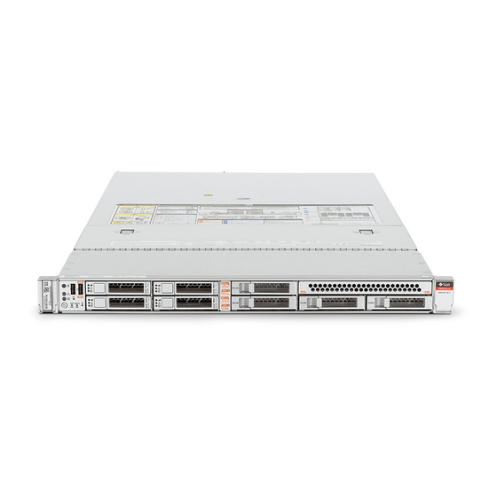
About Controls and Connectors Oracle Server X6-2 Front Panel FIGURE 1 Figure Legend Product Serial Number (PSN) label and Radio Frequency Identification (RFID) tag Locator LED/Locator button: white USB 2.0 connectors (2) Service Required LED: amber Power/OK LED: green... -
Page 16: Server Back Panel View
System status indicators: Locator LED: white, Service Required LED: amber, Power/OK LED: green PCIe card slot 1 (This slot is for a standard PCIe card or the optional Oracle PCIe NVMe switch card. This slot is nonfunctional in single-processor systems.) PCIe card slot 2 PCIe card slots 3 and 4 (Slot 4 is for the internal host bus adapter [HBA] card. -
Page 17: About System Components
About System Components Oracle Integrated Lights Out Manager (ILOM) service processor (SP) network management 10/100/1000BASE- T port (NET MGT) Serial management (SER MGT)/RJ-45 serial port Network (NET) 100/1000/10000 port: NET 3 (Nonfunctional in single-processor systems.) Network (NET) 100/1000/10000 port: NET 2 (Nonfunctional in single-processor systems.) -
Page 18: About System Components
About System Components Server Illustrated Parts Breakdown FIGURE 3 Callout Description Storage drives Front indicator module (FIM) Disk backplane Oracle Server X6-2 Service Manual • June 2016... -
Page 19: Customer-Replaceable Units
About System Components Callout Description Super capacitor (Energy storage module for the Oracle Storage 12 Gb/s SAS PCIe RAID HBA in PCIe slot Fan modules Motherboard Processors Note - In single-processor systems, neither a heatsink nor a processor socket filler are installed in the processor socket 1 (P1). -
Page 20: Field-Replaceable Units
Note - The Oracle Storage 12 Gb/s SAS PCIe RAID HBA card and the optional Oracle PCIe NVMe switch card are field replaceable units (FRUs) and should only be serviced by authorized Oracle Service personnel. PCIe risers Houses and connects the PCIe cards. -
Page 21: Server Internal Cables
“Servicing the Power, FIM, DVD drive to the motherboard. Disk Backplane Data, and DVD Provides a data connection Cables” on page 181 between the two components and provides power from the motherboard to the DVD drive. About the Oracle Server X6-2... - Page 22 About System Components Related Information “Customer-Replaceable Units” on page 19 ■ “Illustrated Parts Breakdown” on page 17 ■ “Servicing FRUs” on page 119 ■ Oracle Server X6-2 Service Manual • June 2016...
-
Page 23: Troubleshooting And Diagnostics
Troubleshooting and Diagnostics This section includes information about troubleshooting hardware component faults for the Oracle Server X6-2. It contains the following topics. Description Link Maintenance-related information and procedures that you can “Troubleshooting Server Component Hardware use to troubleshoot and repair server hardware issues. -
Page 24: Troubleshooting Server Hardware Faults
3. Prepare the server for service using Oracle ILOM. If you have determined that the hardware fault requires service (physical access to the server), use Oracle ILOM to take the server offline, activate the Locate LED, and power off the server. - Page 25 Troubleshoot Hardware Faults Using the Oracle ILOM Web Interface Depending on the component, you might need to clear the fault in Oracle ILOM. Generally, components that have a FRU ID clear the fault automatically. Related Information: “Troubleshoot Hardware Faults Using the Oracle ILOM Web Interface” on page 25 ■...
- Page 26 Troubleshoot Hardware Faults Using the Oracle ILOM Web Interface In the Status section of the Oracle ILOM Summary Information screen, identify the server subsystem that requires service. In the above example, the Status screen shows that the Processor subsystem requires service.
-
Page 27: Troubleshooting And Diagnostic Information
To prepare the server for service, see “Preparing for Service” on page Service the component. After servicing the component, you might need to clear the fault in Oracle ILOM. For more information, refer the service procedures for the component. Troubleshooting and Diagnostic Information The following table lists diagnostic- and troubleshooting-related procedures and references that can assist you with resolving server issues. -
Page 28: Troubleshooting Using The Server Front And Rear Panel Status Indicators
2. After a few minutes, the main Power/OK LED flashes the standby blink pattern (0.1 seconds on, 2.9 seconds off), indicating that the SP (and Oracle ILOM) is ready for use. In standby power mode, the server is not initialized or fully powered on at this point. -
Page 29: Server System-Level Status Indicators
Power/OK Green Indicates the operational state of the chassis. ■ OFF – AC power is not present or the Oracle ILOM boot is not complete. ■ Standby BLINK – Standby power is on, but the chassis power is off and the Oracle ILOM SP is running. -
Page 30: Server Fan Status Indicators
Troubleshoot Hardware Faults Using the Oracle ILOM Web Interface Status Icon Colors State and Meaning Indicator Name Top Fan Amber Indicates that one or more of the internal fan modules have failed. ■ OFF – Indicates steady state; no service is required. -
Page 31: Power Supply Status Indicators
Troubleshoot Hardware Faults Using the Oracle ILOM Web Interface Server Front Storage Drive Indicators TABLE 3 Status Icon Color State and Meaning Indicator Name OK/Activity Green ■ OFF – Power is off or the installed drive is not recognized by the system. -
Page 32: Ethernet Ports Status Indicators
DIMM Fault Status Indicators - Each of the 24 DIMM sockets on the motherboard has ■ an amber fault status indicator (LED) associated with it. If Oracle ILOM determines that a DIMM is faulty, pressing the Fault Remind button on the motherboard signals the service processor to light the fault LED associated with the failed DIMM. -
Page 33: Troubleshooting System Cooling Issues
Troubleshoot Hardware Faults Using the Oracle ILOM Web Interface motherboard. This LED lights to indicate that the fault remind circuitry is working properly in cases where no components have failed and, as a result, none of the component fault LEDs illuminate. For more information on the fault remind status indicator and the location of the Fault Remind Button, see “Using the Server Fault Remind Button”... - Page 34 Troubleshoot Hardware Faults Using the Oracle ILOM Web Interface Prevention: Periodically check the ambient temperature of the server space to ensure that it is within the required range, especially if you have made any changes to the server space (for example, added additional servers).
-
Page 35: Troubleshooting Power Issues
Troubleshoot Hardware Faults Using the Oracle ILOM Web Interface To reduce the risk related to component failure, power supplies and fan modules are installed in pairs to provide redundancy. Redundancy ensures that if one component in the pair fails, the other functioning component can continue to maintain the subsystem. For example, power supplies serve a dual function;... - Page 36 Troubleshoot Hardware Faults Using the Oracle ILOM Web Interface Power Supplies (PSUs) The server power supplies (PSUs) provide the necessary server voltages from the AC power outlets. If the PSUs are inoperable, unplugged, or disengaged from the internal connectors, the server cannot power on.
-
Page 37: Managing Server Hardware Faults Through The Oracle Ilom Fault Management Shell
For more information about how to use the Oracle ILOM Fault Management Shell, see the Oracle ILOM User's Guide for System Monitoring and Diagnostics Firmware Release 3.2.x in the Oracle Integrated Lights Out Manager (ILOM) 3.2 Documentation Library at:... -
Page 38: Troubleshooting With Diagnostic Tools
Diagnostic Tools The selection of diagnostic tools available for your server range in complexity from a comprehensive validation test suite (Oracle VTS) to a chronological event log (Oracle ILOM System Log). The selection of diagnostic tools also include standalone software packages, firmware-based tests, and hardware-based LED indicators. -
Page 39: Diagnostic Tool Documentation
Oracle ILOM Remote System all processor, memory, disk web interface or the Console Plus. drives, and network ports. command-line interface It is used on new Oracle (CLI) to run UEFI systems, such as the Oracle diagnostics. Server X6.2. Oracle Operating... -
Page 40: Attaching Devices To The Server
Connect an Ethernet cable to the Gigabit Ethernet (NET) connectors as needed for OS support. “Rear Panel Connector Locations” on page To connect to the service processor's Oracle ILOM over the network, connect an Ethernet cable to the Ethernet port labeled NET MGT. “Rear Panel Connector Locations” on page... - Page 41 60 seconds if the server is not connected to a terminal, PC, or workstation. Note - Oracle ILOM will signal a fault on any installed power supply that is not connected to an AC power source, since it might indicate a loss of redundancy.
-
Page 42: Configuring Serial Port Sharing
By default, the SP console (SER MGT) port sends serial port output from the server. Using Oracle ILOM, you can specify that the host console (COM1) be assigned as owner of the server serial port output. This feature is useful for Windows kernel debugging, as it enables you to view non-ASCII character traffic from the host console. -
Page 43: Server Operating System Names For The Nvme Storage Drives
Assign Serial Port Output Using the Web Interface To log in, open a web browser and direct it using the IP address of the server SP. Log in as root or a user with administrator privileges. Refer to “Accessing Oracle ILOM” in the Oracle X6 Series Servers Administration Guide. -
Page 44: Rear Panel Pinhole Switches
Additionally, Windows allows you to rename the ports to meet application-specific needs. Rear Panel Pinhole Switches This section shows the location of the rear panel pinhole switches and describes the function of each switch. Oracle Server X6-2 Service Manual • June 2016... -
Page 45: Getting Help
TABLE 8 Figure Legend Description Host Warm Reset NMI (non-maskable interrupt) (For use by authorized Oracle Service personnel only.) SP Reset Getting Help The following sections describe how to get additional help to resolve server-related problems. “Contacting Support” on page 45 ■... -
Page 46: Locating The Chassis Serial Number
This sheet includes the serial number. Using Oracle ILOM: ■ ■ From the command-line interface (CLI), type the command: show/SYS. From the web interface, view the serial number on the System Information screen. ■ Oracle Server X6-2 Service Manual • June 2016... -
Page 47: Preparing For Service
Follow all standard cautions, warnings, and instructions marked on the equipment and ■ described in the online Oracle Server X6-2 Safety and Compliance Guide and in the printed Important Safety Information for Oracle's Hardware Systems. Ensure that the voltage and frequency of your power source match the voltage and ■... -
Page 48: Safety Symbols
Wear an antistatic wrist strap and use an antistatic mat when handling components such as drive assemblies, boards, or cards. When servicing or removing server components, attach an antistatic strap to your wrist and then to a metal area on the chassis. Then disconnect Oracle Server X6-2 Service Manual • June 2016... -
Page 49: Fru Key Identity Properties (Kip) Automated Update
■ When a server FRU that contains the KIP is removed and a replacement component is installed, the KIP of the replacement component is programmed by Oracle ILOM to contain the same KIP as the other two components. Preparing for Service... -
Page 50: Related Information
“Powering Down the Server” on page 51 ■ “Disconnect Cables From the Server” on page 56 ■ “Extend the Server to the Maintenance Position” on page 56 ■ “Remove the Server From the Rack” on page 58 ■ Oracle Server X6-2 Service Manual • June 2016... -
Page 51: Powering Down The Server
Depending on the nature of the problem, you might want to view the system status or the log files or run diagnostics before you shut down the system. For more information, see the Oracle ILOM 3.2 Documentation Library at http://www.oracle.com/goto/ilom/docs. - Page 52 At the Oracle ILOM prompt, shut down the operating system: stop /System -> If the system is running the Oracle Solaris OS, refer to the Oracle Solaris system administration documentation for additional information. Disconnect the power cords and data cables from the server.
-
Page 53: Power Down Server Gracefully Using The Power Button
Table 1 ■ “Power Down Server Gracefully Using the Oracle ILOM CLI” on page 51 ■ “Power Down Server Gracefully Using the Oracle ILOM Web Interface” on page 52 ■ “Use the Power Button for Immediate Shutdown” on page 54 ■... -
Page 54: Use The Oracle Ilom Cli For Immediate Shutdown
■ “Power Down Server Gracefully Using the Oracle ILOM CLI” on page 51 ■ “Power Down Server Gracefully Using the Oracle ILOM Web Interface” on page 52 ■ “Power Down Server Gracefully Using the Power Button” on page 53 ■... -
Page 55: Use The Oracle Ilom Web Interface For Immediate Shutdown
Related Information “Use the Power Button for Immediate Shutdown” on page 54 ■ “Use the Oracle ILOM Web Interface for Immediate Shutdown” on page 55 ■ Use the Oracle ILOM Web Interface for Immediate Shutdown An immediate power down might corrupt system data, so only use this procedure to Caution - power down the server after attempting the graceful power down procedure. -
Page 56: Disconnect Cables From The Server
PCIe cards and cables ■ SAS cables ■ NVMe cables ■ DIMMs ■ Internal USB flash drives ■ Motherboard battery ■ Processors ■ Disk backplane ■ FIM (front indicator module) ■ Motherboard ■ Oracle Server X6-2 Service Manual • June 2016... - Page 57 Caution - all anti-tilt devices before extending the server from the rack. For instructions for stabilizing the rack, see the “Stabilize the Rack for Installation” in Oracle Server X6-2 Installation Guide. Verify that no cables will be damaged or will interfere when the server is extended.
-
Page 58: Remove The Server From The Rack
“Disconnect Cables From the Server” on page 56 ■ “Take Antistatic Measures” on page 59 ■ “Extend the Server to the Maintenance Position” on page 56 ■ “Reinstall the Server Into the Rack” on page 190 ■ Oracle Server X6-2 Service Manual • June 2016... -
Page 59: Take Antistatic Measures
The following items can be used as an antistatic mat: An antistatic bag used to wrap a replacement part ■ An Oracle ESD mat (orderable item) ■ A disposable ESD mat (shipped with some replacement parts or optional system ■... -
Page 60: Remove The Server Top Cover
To open the server top cover, press and hold down the top cover release button and use the recessed area to slide the top cover toward the rear of the server about 0.5 inches (12.7 mm) [1]. Oracle Server X6-2 Service Manual • June 2016... - Page 61 Remove the Server Top Cover Removing the Server Top Cover FIGURE 6 Lift the cover off the chassis and set it aside [2]. Related Information “Take Antistatic Measures” on page 59 ■ “Install the Server Top Cover” on page 188 ■...
- Page 62 Oracle Server X6-2 Service Manual • June 2016...
-
Page 63: Servicing Crus That Do Not Require Server Power-Off
“Removing and Replacing a HDD or SSD Storage Drive” on page 66 ■ “Removing and Replacing an NVMe Storage Drive Using Oracle Solaris” on page 69 ■ “Removing and Replacing an NVMe Storage Drive Using Oracle Linux” on page 72 ■... -
Page 64: Storage Drives Hot-Plug Conditions
For instructions for configuring RAID on the server, refer to “Configuring Storage Drives for Operating System Installation” in Oracle Server X6-2 Installation Guide. Storage Drive Locations and Numbering The following illustration and table show the locations of the HDD, SSD, and optional NVMe SSD drives. -
Page 65: Storage Drive Status Indicators
Drive 7 (HDD/SSD) NVMe0) NVMe2) If the optional Oracle PCIe NVMe switch card is installed in the server, the associated Note - NVMe storage drives are installed in drive locations 2, 3, 4, and 5, as shown in the above table. -
Page 66: Removing And Replacing A Hdd Or Ssd Storage Drive
The exact commands required depend on the configuration of your drives. Unmount file systems or issue RAID commands as needed. On the drive you plan to remove, push the latch release button to open the drive latch. Oracle Server X6-2 Service Manual • June 2016... - Page 67 Remove a HDD or SSD Storage Drive Locating the Hard Disk Drive Release Button and Latch FIGURE 9 The latch is not an ejector. Do not open the latch too far to the right. Doing so can Caution - damage the latch.
-
Page 68: Figure 10
“Storage Drive Status Indicators” on page 65 ■ “Storage Drives Hot-Plug Conditions” on page 64 ■ “Storage Drive Failure and RAID” on page 64 ■ “Remove a HDD or SSD Storage Drive” on page 66 ■ Oracle Server X6-2 Service Manual • June 2016... -
Page 69: Removing And Replacing An Nvme Storage Drive Using Oracle Solaris
Removing and Replacing an NVMe Storage Drive Using Oracle Solaris NVMe storage drives are supported only on servers that are running the Oracle Solaris or Note - Oracle Linux operating system. Servers that are running Oracle VM, Windows Server, or Red Hat Enterprise Linux do not support NVMe drives. -
Page 70: Grasp The Latch And Pull The Drive Out Of The Drive Slot
# hotplug list –lc Connection State Description Path ------------------------------------------------------------------ pcie13 EMPTY PCIe-Native /pci@7a,0/pci8086,2f08@3/pci111d,80b5@4 Install an NVMe Storage Drive in the Server Perform this procedure to physically install an NVMe storage drive into the server. Oracle Server X6-2 Service Manual • June 2016... - Page 71 Power On an NVMe Storage Drive and Attach a Device Driver After you physically remove an NVMe storage drive from the server, wait at least 10 Note - seconds before installing a replacement drive. Remove the replacement drive from its packaging and place the drive on an antistatic mat.
-
Page 72: Removing And Replacing An Nvme Storage Drive Using Oracle Linux
Using Oracle Linux Note - NVMe storage drives are supported only on servers that are running the Oracle Solaris or Oracle Linux operating system. Servers that are running Oracle VM, Windows Server, or Red Hat Enterprise Linux do not support NVMe drives. - Page 73 Remove an NVMe Storage Drive /sys/bus/pci/slots/13/address:0000:b4:00 (instance nvme1, pcie slot 13, drive label nvme3) In the above output, the bus addresses for the corresponding NVMe instances are highlighted in bold text. In the above output, notice that the instance names for the NVMe drives does not Note - correspond to the NVMe drive labels on the front of the server, that is, pci/slots/12/address: 0000:b2:00 corresponds to instance nvme0;...
-
Page 74: Drive" On Page
After you physically remove an NVMe drive from the server, wait at least 10 seconds before installing a replacement drive. Remove the replacement drive from its packaging and place the drive on an antistatic mat. Oracle Server X6-2 Service Manual • June 2016... -
Page 75: Servicing Fan Modules (Cru)
Power On an NVMe Storage Drive and Attach a Device Driver If necessary, remove the drive filler panel. Align the replacement drive with the drive slot. The drive is physically addressed according to the slot in which it is installed. It is important to install a replacement drive in the same slot as the drive that was removed. -
Page 76: Remove A Fan Module
Oracle ILOM. Even if only one fan motor is faulted within the fan module, the Oracle ILOM service processor detects that four fan motors have failed to spin while the fan module is removed. ... - Page 77 Remove a Fan Module Server Fan Module Status Indicator FIGURE 11 Status Color State Meaning Indicator Name Fan Module Off/Amber ■ Off – The fan module is correctly installed and operating within Status specification. ■ Amber – The fan module is faulty. The front TOP FAN LED and the front and rear panel Service Required LEDs are also lit if the system detects a fan module fault.
- Page 78 If you removed the fan assembly as part of another procedure, return to that procedure. ■ Otherwise, continue to “Install a Fan Module” on page ■ Related Information “Install a Fan Module” on page 79 ■ Oracle Server X6-2 Service Manual • June 2016...
-
Page 79: Install A Fan Module
Install a Fan Module Install a Fan Module Remove the replacement fan module from its packaging and place it on an antistatic mat. With the fan door open, position the replacement fan module into the server. The fan modules are keyed to ensure that they are installed in the correct orientation. Installing a Fan Module FIGURE ... -
Page 80: Servicing Power Supplies (Cru)
For more information, refer to the following topic and procedures: “Power Supply Status Indicators” on page 81 ■ “Remove a Power Supply” on page 81 ■ “Install a Power Supply” on page 83 ■ Oracle Server X6-2 Service Manual • June 2016... -
Page 81: Power Supply Status Indicators
A lit amber Service Required LED on a power supply indicates that a failure was detected. You can also use the Oracle ILOM show faulty command at the Oracle ILOM command line prompt (->) to identify a power supply failure. -
Page 82: Oracle Server X6-2 Service Manual • June
Remove a Power Supply Alternatively, to list all known faults in the server, log into the Oracle Solaris OS and issue the fmadm faulty command, or log into the Oracle ILOM service processor from the Oracle ILOM Fault Management Shell and issue the fmadm faulty command. For more information about how to use the Oracle ILOM Fault Management Shell and supported commands, see the Oracle ILOM User's Guide for System Monitoring and Diagnostics Firmware Release 3.2.x in... -
Page 83: Install A Power Supply
Install a Power Supply Figure Legend Power Supply 0 (PS0) Power Supply 1 (PS1) Pull the power supply out of the chassis [2]. Whenever you remove a power supply, you should replace it with another power Caution - supply; otherwise, the server might overheat due to improper airflow. Continue to “Install a Power Supply”... - Page 84 Verify that the amber LED on the replaced power supply and the Service Required LEDs on the front and rear panels of the server are not lit. After you have replaced Power Supply 0, you must reset the Oracle ILOM service Note - processor (SP) to propagate the key identity properties (KIP) data to the new power supply.
-
Page 85: Servicing Crus That Require Server Power-Off
“Servicing FRUs” on page 119 ■ Servicing the DIMMs (CRU) The Oracle Server X6-2 supports a variety of DDR4 DIMM configurations that can include quad-rank (QR) and dual-rank (DR) DDR4 DIMMs. These procedures require that you handle components that are sensitive to Caution - electrostatic discharge. -
Page 86: Dimm And Processor Physical Layout
0 (P0) is on the left. Notice that each processor, P0 and P1, has four memory channels that are labeled, from left to right, Ch C, Ch D, Ch B, and Ch Oracle Server X6-2 Service Manual • June 2016... -
Page 87: Dimm Population Scenarios
Servicing the DIMMs (CRU) DIMM and Processor Physical Layout FIGURE 16 In single-processor systems, the DIMM sockets associated with the processor 1 (P1) Note - are nonfunctional and should not be populated with DIMMs. A maximum of 12 DIMMs are supported in single-processor systems and the DIMMs must be installed in DIMM sockets associated with the P0 processor socket. -
Page 88: Dimm Population Rules
■ Populate the DIMM sockets in the order described in the following sections. ■ The following sections provide an example of how to populate the DIMM sockets to achieve optimal system performance. Oracle Server X6-2 Service Manual • June 2016... - Page 89 Servicing the DIMMs (CRU) Not all possible configurations are shown here. Note - “Populating DIMMs in Single-Processor Systems for Optimal System ■ Performance” on page 89 “Populating DIMMs in Dual-Processor Systems for Optimal System ■ Performance” on page 90 Populating DIMMs in Single-Processor Systems for Optimal System Performance In single-processor systems, install DIMMs only into DIMM sockets associated with processor 0 (P0).
- Page 90 DIMM sockets is Ch C first, Ch A second, Ch D third, and Ch B last. Repeat the same population sequence for the black sockets with white tabs, and finally, for the white sockets. Oracle Server X6-2 Service Manual • June 2016...
- Page 91 Servicing the DIMMs (CRU) DIMM Population Order for Dual-Processor Systems FIGURE 18 The following table describes the proper order in which to install DIMMs in a dual-processor system using the numbered callouts in the above figure, the memory channels labels (Ch A through Ch D), and the DIMM socket labels (D0 through D11).
-
Page 92: Dimm Operating Speeds
Inconsistencies Between DIMM Fault Indicators and the BIOS Isolation of Failed DIMMs When a single DIMM is marked as failed by Oracle ILOM (for example, fault.memory. intel.dimm.training-failed is listed in the service processor Event Log), BIOS might disable the entire memory channel that contains the failed DIMM, up to three DIMMs. As a result, none of the memory installed in the disabled channel will be available to the operating system. -
Page 93: Identify And Remove The Failed Dimm
Identify and Remove the Failed DIMM any fault LEDs that were lit due to a component failure. If this LED does not light when you press the Fault Remind button, it is likely that the capacitor powering the fault remind circuit has lost its charge. - Page 94 To remove the failed DIMM do the following: a. Rotate both DIMM socket ejectors outward as far as they will go (See Figure 20). The DIMM is partially ejected from the socket. Oracle Server X6-2 Service Manual • June 2016...
-
Page 95: Install A Dimm
Install a DIMM DIMM Socket Release and Alignment FIGURE 20 Figure Legend DIMM connector socket DIMM connector key DIMM ejector lever b. Carefully lift the DIMM straight up to remove it from the socket. Replace each failed DIMM with either another DIMM of the same rank size (quad rank or dual rank) or leave the socket empty. - Page 96 “Reconnect Data Cables and Power Cords” on page 193. e. Power on the server. “Power On the Server” on page 194. Verify that the Power/OK status indicator is steady on. Oracle Server X6-2 Service Manual • June 2016...
-
Page 97: Servicing Pcie Risers (Cru)
(Optional) Use Oracle ILOM to clear server DDR4 DIMM faults. DDR4 DIMM faults are automatically cleared after a new DIMM has been installed. If you need to manually clear DDR4 DIMM faults, refer to the Oracle Integrated Lights Out Manager (ILOM) 3.2 Documentation Library at http://www.oracle.com/goto/ilom/docs. -
Page 98: Pcie Riser Location And Differences
FIGURE 21 PCIe Riser Locations Figure Legend PCIe riser and installed PCIe card or the optional Oracle PCIe NVMe switch card in slot 1 (This slot is nonfunctional in single-processor systems.) PCIe riser and installed PCIe card in slot 2... -
Page 99: Remove A Pcie Riser From Pcie Slot 1 Or 2
PCIe riser for slot 1. The PCIe NVMe switch card is a field replaceable unit (FRU) and, therefore, must be removed and replaced only by authorized Oracle Services personnel. For instructions for servicing the PCIe NVMe switch card, see “Servicing the Oracle... - Page 100 PCIe riser was originally installed; otherwise, set the PCIe riser aside. Related Information “Install a PCIe Riser Into PCIe Slot 1 or 2” on page 101 ■ Oracle Server X6-2 Service Manual • June 2016...
-
Page 101: Install A Pcie Riser Into Pcie Slot 1 Or 2
Install a PCIe Riser Into PCIe Slot 1 or 2 Install a PCIe Riser Into PCIe Slot 1 or 2 PCIe slot 1 is nonfunctional in single-processor systems. Note - The PCIe riser in slots 3 and 4 is different than the PCIe risers in slots 1 and 2. Do not Note - attempt to install a PCIe riser from slot 1 or 2 into PCIe slots 3 and 4 and vice versa. - Page 102 Use Oracle ILOM to clear the server PCIe riser fault. If the PCIe riser fault message in Oracle ILOM is not cleared under Open Problems, you must manually clear the fault in Oracle ILOM. For instructions for manually clearing a PCIe riser fault, see the procedure "Clear Faults for Undetected Replaced or Repaired...
-
Page 103: Remove The Pcie Riser From Pcie Slots 3 And 4
Remove the PCIe Riser From PCIe Slots 3 and 4 Remove the PCIe Riser From PCIe Slots 3 and 4 This PCIe riser is actually installed in PCIe slot 3, but it supports up to two PCIe cards. Note - The upper slot, referred to as slot 3, can be used for any supported PCIe card, and, therefore, is optionally populated. - Page 104 Grasp the riser with both hands and remove it from the server [4]. Disconnect the SAS storage drive (HDD) cables from the internal HBA card installed in PCIe slot 4. Disconnect the super capacitor cable from the internal HBA card in slot 4. Oracle Server X6-2 Service Manual • June 2016...
-
Page 105: Install The Pcie Riser Into Pcie Slots 3 And 4
Install the PCIe Riser Into PCIe Slots 3 and 4 Place the riser on an antistatic mat. Related Information “Install the PCIe Riser Into PCIe Slots 3 and 4” on page 105 ■ Install the PCIe Riser Into PCIe Slots 3 and 4 The PCIe riser in slots 3 and 4 is different than the PCIe risers in slots 1 and 2. - Page 106 Slide the plastic PCIe card retainer, which is mounted on the side of the chassis, toward the back of the server to secure the card(s) installed in the riser [2]. Oracle Server X6-2 Service Manual • June 2016...
- Page 107 Use Oracle ILOM to clear the server PCIe riser fault. If the PCIe riser fault message in Oracle ILOM is not cleared under Open Problems, you must manually clear the fault in Oracle ILOM. For instructions for manually clearing a PCIe riser fault, see the procedure "Clear Faults for Undetected Replaced or Repaired...
-
Page 108: Servicing Pcie Cards (Cru)
The procedures in this section should not be used to service the internal HBA card (Oracle Storage 12 Gb/s SAS PCIe RAID HBA card) that is located in PCIe slot 4 or the optional Oracle PCIe NVMe switch card that is located in PCIe slot 1. The internal HBA card and the Oracle PCIe NVMe switch card are Field Replaceable Units (FRUs) and should not be serviced by customers. -
Page 109: Remove A Pcie Card From Pcie Slot 1 Or 2
PCIe riser for slot 1. The PCIe NVMe switch card is a field replaceable unit (FRU) and, therefore, must be removed and replaced only by authorized Oracle Services personnel. For instructions for servicing the PCIe NVMe switch card, see “Servicing the Oracle... -
Page 110: Install A Pcie Card In Pcie Slot 1 Or 2
PCIe slot 1 is nonfunctional in single-processor systems. Note - Retrieve the PCIe card and riser you want to install. Insert the rear bracket that is attached to the PCIe card into the PCIe riser. Oracle Server X6-2 Service Manual • June 2016... -
Page 111: Remove A Pcie Card From Pcie Slot 3
Remove a PCIe Card From PCIe Slot 3 Hold the riser in one hand and use your other hand to carefully insert the PCIe card connector into the Riser. Install the PCIe riser into the server. For instructions, see “Install a PCIe Riser Into PCIe Slot 1 or 2” on page 101. -
Page 112: Install A Pcie Card In Pcie Slot 3
Install a PCIe Card in PCIe Slot 3 Retrieve the PCIe card and riser you want to install. Insert the rear bracket that is attached to the PCIe card into the PCIe riser. Oracle Server X6-2 Service Manual • June 2016... -
Page 113: Servicing The Internal Usb Flash Drives (Cru)
Servicing the Internal USB Flash Drives (CRU) Hold the riser in one hand and use your other hand to carefully insert the PCIe card connector into the riser. Install the PCIe riser. For instructions, see “Install the PCIe Riser Into PCIe Slots 3 and 4” on page 105. -
Page 114: Remove An Internal Usb Flash Drive
“Take Antistatic Measures” on page d. Remove the server top cover. “Remove the Server Top Cover” on page Grasp the USB flash drive and pull it out of the internal USB port . Oracle Server X6-2 Service Manual • June 2016... -
Page 115: Install An Internal Usb Flash Drive
Install an Internal USB Flash Drive Removing an Internal USB Flash Drive FIGURE 22 Install an Internal USB Flash Drive Unpack the replacement USB flash drive. Insert the USB flash drive into the internal USB port (see Figure 22). Return the server to operation. -
Page 116: Servicing The Battery (Cru)
Power off the server and disconnect the power cords from the power supplies. “Powering Down the Server” on page b. Extend the server to the maintenance position. “Extend the Server to the Maintenance Position” on page Oracle Server X6-2 Service Manual • June 2016... -
Page 117: Install The Battery
Install the Battery c. Attach an antistatic wrist strap to your wrist and then to a metal area on the chassis. “Take Antistatic Measures” on page Remove the server top cover. d. “Remove the Server Top Cover” on page If there is a PCIe card installed in the PCIe riser slot 2, remove the riser and card to gain access to the battery. - Page 118 If the service processor is configured to synchronize with a network time server using the Network Time Protocol (NTP), the Oracle ILOM clock will be reset as soon as the server is powered on and connected to the network; otherwise, proceed to the next step.
-
Page 119: Servicing Frus
“Field-Replaceable Units” on page You must power down the system and disconnect the AC power cords from the server before servicing any of these components. Only authorized Oracle Services personnel should service FRUs. Note - Description Link Service the processors. -
Page 120: Servicing Processors (Fru)
Servicing Processors (FRU) Servicing Processors (FRU) Processors should be removed and replaced only by authorized Oracle Services Note - personnel. Ensure that all power is removed from the server before removing or installing a Caution - processor. You must disconnect the power cables from the server before performing these procedures. - Page 121 The processors supported by the Oracle Server X6-2 come in two sizes. The processors with 10 or fewer cores are smaller than the processors with 12 or more cores. You can determined the size of the processor that you are going to remove and replace in either of two ways: Use Oracle Integrated Lights Out Manager (ILOM) 3.2 to display processor information.
- Page 122 Processor left and right edges are within alignment bracket boundaries Figure 25 shows a larger processor installed. Notice that the right and left edges of the processor extend beyond the boundaries of the processor alignment brackets. Oracle Server X6-2 Service Manual • June 2016...
- Page 123 Servicing Processors (FRU) Larger Processor Installed in a Motherboard Processor Socket FIGURE 25 Figure Legend Processor alignment brackets Processor left and right edges extend beyond alignment bracket boundaries After you have determined the size of the processor installed in your server, select the correct processor removal and replacement tool.
- Page 124 22-core E5-2699 V4 The correct processor removal and replacement tool is included in the box with the Note - replacement processor. Additionally, both removal and replacement tools ship with replacement motherboards. Oracle Server X6-2 Service Manual • June 2016...
-
Page 125: Remove A Processor
Power, FIM, Disk Backplane Data, and DVD Cables” on page 181. If the server has an Oracle PCIe NVMe switch card installed, disconnect the switch card cables from the disk backplane, carefully pull them through the chassis mid-wall, and move them to side away from the air baffle. - Page 126 Processor 0 (P0) fault LED Processor 1 (P1) fault LED Gently press down on the top of the heatsink to counteract the pressure of the captive spring-loaded screws that secure the heatsink to the motherboard and Oracle Server X6-2 Service Manual • June 2016...
- Page 127 Remove a Processor loosen the four Phillips captive screws in the heatsink for the failed processor [1]. Using a No. 2 Phillips screwdriver, turn the screws counterclockwise alternately one and one half turns until they are fully removed. To separate the heatsink from the top of the processor, gently twist the heatsink left and right, while pulling upward, and then lift off the heatsink and place it upside down on a flat surface [1].
- Page 128 Press the release lever on the tool to release the center button and engage the processor [3]. An audible click indicates that the processor is engaged. Oracle Server X6-2 Service Manual • June 2016...
- Page 129 Remove a Processor d. Grasp the tool by the sides and remove it from the server [4]. e. Turn the tool upside down and verify that it contains the processor [5]. f. While holding the processor tool up side down, press the center button on the tool to release the processor [5].
- Page 130 Remove a Processor Removing a Processor FIGURE 28 Related Information “Install a Processor” on page 131 ■ Oracle Server X6-2 Service Manual • June 2016...
-
Page 131: Install A Processor
Install a Processor Install a Processor Caution - Processors should be installed only by an Oracle qualified service technician. Processor removal and replacement must be done using the correct removal and Caution - replacement tool; otherwise, damage might result to the processor or the processor socket. - Page 132 For information on how to select the correct processor removal and replacement tool, see “Selecting the Correct Processor Removal and Replacement Tool” on page 120. Oracle Server X6-2 Service Manual • June 2016...
- Page 133 Install a Processor Installing a Processor FIGURE 29 Visually check the alignment of the processor in the socket. When properly aligned, the processor sits flat in the processor socket. Servicing FRUs...
- Page 134 Use the syringe (supplied with the new or replacement processor) to apply approximately 0.1 ml of thermal grease to the center of the top of the processor. To measure 0.1 ml of thermal grease, use the graduated scale on the thermal grease syringe. Oracle Server X6-2 Service Manual • June 2016...
- Page 135 Install a Processor Do not distribute the grease; the pressure of the heatsink will do so for you when you Note - install the heatsink. Inspect the heatsink for dust and lint. Clean the heatsink if necessary. Orient the heatsink so that the screws line up with the mounting studs [3]. Note - The processor heatsink is not symmetrical.
-
Page 136: Power Supplies
To show server faults, log in to the server as root using the Oracle ILOM CLI, and type the following command to list all known faults on the system: -> show /SP/faultmgmt... -
Page 137: Servicing The Oracle Pcie Nvme Switch Card (Fru)
Servicing the Oracle PCIe NVMe Switch Card (FRU) Set ‘clear_fault_action’ to ‘true’ Alternatively, to clear all known faults in the server, log into the Oracle Solaris OS and issue the fmadm repair command, or log into the Oracle ILOM service processor from the Oracle ILOM Fault Management Shell and issue the fmadm repair command. -
Page 138: Remove The Oracle Pcie Nvme Switch Card From Pcie Slot 1
Remove the Oracle PCIe NVMe Switch Card From PCIe Slot 1 Remove the Oracle PCIe NVMe Switch Card From PCIe Slot 1 Prepare the server for service. a. Power off the server and disconnect the power cords from the power supplies. -
Page 139: Install The Oracle Pcie Nvme Switch Card In Pcie Slot 1
Install the Oracle PCIe NVMe Switch Card in PCIe Slot 1 Disconnect the internal cables that connect the switch card to the disk backplane. Hold the riser in one hand and use your other hand to carefully remove the card from the riser. -
Page 140: Servicing The Internal Hba Card (Fru)
“Power On the Server” on page 194. Verify that the Power/OK status indicator is steady on. Servicing the Internal HBA Card (FRU) The following sections provide information to assist you when servicing the internal HBA card: Oracle Server X6-2 Service Manual • June 2016... -
Page 141: Remove The Internal Hba Card From Pcie Slot 4
Remove the Internal HBA Card From PCIe Slot 4 These procedures require that you handle components that are sensitive to Caution - electrostatic discharge. This sensitivity can cause the components to fail. To avoid damage, ensure that you follow antistatic practices as described in “Take Antistatic Measures”... - Page 142 Hold the riser in one hand and use your other hand to carefully remove the card from slot 4 of the riser. Disconnect the rear bracket attached to the PCIe card from the rear of the b. PCIe riser. Oracle Server X6-2 Service Manual • June 2016...
- Page 143 Remove the Internal HBA Card From PCIe Slot 4 Disconnect the SAS cables and the super capacitor cable from the internal HBA card and place the card on an antistatic mat. If you are replacing the internal HBA card, use a No. 2 Philips screwdriver to remove the special fitted bracket from the HBA card.
- Page 144 Remove the Internal HBA Card From PCIe Slot 4 You will need to install the special fitted bracket on the replacement HBA card. Set aside the bracket until you are ready to install the replacement HBA card. Oracle Server X6-2 Service Manual • June 2016...
-
Page 145: Install The Internal Hba Card In Pcie Slot 4
Install the Internal HBA Card in PCIe Slot 4 Lift the super capacitor up to release the reclosable fasteners that secure it to the server's chassis [2]. Disconnect the super capacitor cable from the super capacitor and place the super capacitor on an antistatic mat [2]. Carefully slide the SAS cables and super capacitor cable through the chassis mid-wall and remove the cables from the server. - Page 146 Install the Internal HBA Card in PCIe Slot 4 Using a No. 2 Philips screwdriver, remove the standard HBA bracket that shipped with the replacement HBA card. Oracle Server X6-2 Service Manual • June 2016...
- Page 147 Install the Internal HBA Card in PCIe Slot 4 Install the special fitted bracket that was removed in Step 5 “Remove the Internal HBA Card From PCIe Slot 4” on page 141. Carefully guide the SAS cables and super capacitor cable that connect to the disk backplane and the super cable through the chassis mid-wall toward the front of the server.
- Page 148 Press the super capacitor into the server's chassis so that it is secured to the existing reclosable fastener [1 and 2]. Connect the SAS cables and the super capacitor cable to the internal HBA card. Oracle Server X6-2 Service Manual • June 2016...
- Page 149 Install the Internal HBA Card in PCIe Slot 4 Insert the rear bracket on the internal HBA card into the rear connector on the PCIe riser. Insert the internal HBA card connector into the bottom connector on the riser for PCIe slot 3 and 4 .
-
Page 150: Servicing The Disk Backplane (Fru)
Verify that the Power/OK status indicator is steady on. Servicing the Disk Backplane (FRU) The disk backplane should be serviced only by authorized Oracle Services personnel. Caution - The following sections provide information to assist you when servicing the disk backplane:... - Page 151 Remove the Disk Backplane c. Attach an antistatic wrist strap to your wrist, and then to a metal area on the chassis. “Take Antistatic Measures” on page d. Open the server fan door to gain access to the disk backplanes. “Open the Server Fan Door”...
- Page 152 Remove six Philips screws from the disk cage cover and slide toward the front of the server and lift up to remove it [frame 1]. Disconnect the SAS cables and the switch card cables (if present) from the disk backplane [2]. Oracle Server X6-2 Service Manual • June 2016...
-
Page 153: Install The Disk Backplane
Related Information “Install the Disk Backplane” on page 153 ■ Install the Disk Backplane The disk backplane should be installed only by authorized Oracle Services personnel. Caution - To place the backplane into the disk cage, do the following: a. ... - Page 154 Turn the disk backplane captive screw clockwise until the disk backplane is secure [1, 5]. Reconnect the disk backplane power cable to the disk backplane [2]. If the server has a DVD drive, perform the following steps: Oracle Server X6-2 Service Manual • June 2016...
- Page 155 Install the Disk Backplane a. Install the DVD drive into the disk drive cage. “Install the DVD Drive” on page 158 Reconnect the DVD cable signal connector to the DVD drive [3]. b. Reconnect the DVD cable power connector to the disk backplane [3]. c. ...
-
Page 156: Servicing The Dvd Drive (Fru)
Extend the server to the maintenance position. b. “Extend the Server to the Maintenance Position” on page Attach an antistatic wrist strap to your wrist and then to a metal area on the c. chassis. Oracle Server X6-2 Service Manual • June 2016... - Page 157 Remove the DVD Drive “Take Antistatic Measures” on page d. Remove the server top cover. “Remove the Server Top Cover” on page Locate the DVD drive [1]. Disconnect the cable from the rear of the DVD [2]. FIGURE 30 Removing the DVD Drive To disengage the DVD drive from the chassis, press and hold the release tab on the rear of the DVD drive up slightly [3].
-
Page 158: Install The Dvd Drive
Verify that the Power/OK status indicator is steady on. Related Information “Remove the DVD Drive” on page 156 ■ Servicing the Front Indicator Module (FRU) The front indicator module should be serviced only by authorized Oracle Services Caution - personnel. Oracle Server X6-2 Service Manual • June 2016... -
Page 159: Remove The Front Indicator Module
“Take Antistatic Measures” on page 59 ■ “Open the Server Fan Door” on page 59 ■ Remove the Front Indicator Module The front indicator module should be removed only by authorized Oracle Services Caution - personnel. Prepare the server for service. a. ... - Page 160 Disconnect the FIM cable from the FIM assembly and set the assembly aside [3]. Continue to “Install the Front Indicator Module ” on page 161. Related Information “Install the Front Indicator Module ” on page 161 ■ Oracle Server X6-2 Service Manual • June 2016...
-
Page 161: Install The Front Indicator Module
Install the Front Indicator Module Install the Front Indicator Module The front indicator module should be installed only by authorized Oracle Services Caution - personnel. Attach an antistatic wrist strap to your wrist, and then to a metal area on the chassis. -
Page 162: Servicing The Motherboard (Fru)
Use the Oracle ILOM backup utility prior to removing the motherboard. This utility Caution - backs up the Oracle ILOM configuration of the service processor. For more information, see the Oracle ILOM 3.2 Documentation Library at http://www.oracle.com/goto/ilom/docs. Prepare the server for service. - Page 163 (KIP) data might be lost. When a server requires service, the KIP is used by Oracle to verify that the warranty on the server has not expired. For more information on KIP, see “FRU Key Identity Properties (KIP) Automated Update”...
- Page 164 [1]. To eject the disk backplane auxiliary power and signal cable connector, open both side latches [2]. To eject the FIM cable connector, open both side latches [3]. Oracle Server X6-2 Service Manual • June 2016...
- Page 165 Remove the Motherboard If the server has a DVD drive, do the following: a. Disconnect the DVD drive cable from the motherboard [4]. b. To remove the DVD drive cable off of the motherboard, carefully guide it through the chassis mid-wall and place it on top of the disk cage so that it is away from the motherboard.
- Page 166 (viewing the server from the front) by pushing down on the lever and moving it to the side away from the processor, and then rotating the lever upward [Frame 1]. Oracle Server X6-2 Service Manual • June 2016...
- Page 167 Remove the Motherboard b. Disengage the processor ILM assembly load lever on the left side of the processor socket (viewing the server from the front) by pushing down on the lever and moving it to the side away from the processor, and then rotating the lever upward [1].
- Page 168 ILM assembly load plate so that 1) the arrow on the processor socket cover is aligned with the arrow on the load plate and 2) the fasteners on one side of the cover (the Oracle Server X6-2 Service Manual • June 2016...
-
Page 169: Install The Motherboard
“Install the Motherboard” on page 169 ■ Install the Motherboard The motherboard should be installed only by an Oracle qualified service technician. Caution - Attach an antistatic wrist strap to your wrist, and then to a metal area on the chassis. - Page 170 Install the Motherboard c. Ensure that the indicators, controls, and connectors on the rear of the motherboard fit correctly into the rear of the server chassis. Install the server mid-wall [2]. Oracle Server X6-2 Service Manual • June 2016...
- Page 171 If the server is equipped with the switch card, reconnect the cables to the a. card and install it in PCIe slot 1. For instructions, see “Install the Oracle PCIe NVMe Switch Card in PCIe Slot 1” on page 139. b. ...
- Page 172 (KIP) data might be lost. When a server requires service, the KIP is used by Oracle to verify that the warranty on the server has not expired. For more information on KIP, “FRU Key Identity Properties (KIP) Automated Update” on page For instructions, see “Install a Power Supply”...
-
Page 173: Servicing The Internal Hba Sas Cable Assembly
Servicing the Internal HBA SAS Cable assembly Servicing the Internal HBA SAS Cable assembly The internal HBA SAS cable assembly should be serviced only by authorized Oracle Caution - Services personnel. These procedures require that you handle components that are sensitive to Caution - electrostatic discharge. - Page 174 “Remove the PCIe Riser From PCIe Slots 3 and 4” on page 103. To disconnect each SAS cables from the disk backplane, press the latch on the cable connectors and pull the connectors out. [1]. Oracle Server X6-2 Service Manual • June 2016...
- Page 175 Remove the Internal HBA SAS Cable Assembly Removing the SAS Cables and the Super Capacitor Cable FIGURE 32 Disconnect the SAS cables and the super capacitor cable from the internal host bus adapter (HBA). Servicing FRUs...
-
Page 176: Install The Internal Hba Sas Cable Assembly
“Install the Internal HBA SAS Cable Assembly” on page 176 ■ Install the Internal HBA SAS Cable Assembly The internal HBA SAS cable assembly should be installed only by an Oracle Caution - qualified service technician. Carefully guide SAS cables and the super capacitor cable along the side of the chassis. -
Page 177: Servicing The Nvme Cables
“Remove the Internal HBA SAS Cable Assembly” on page 173 ■ Servicing the NVMe Cables The NVMe cables should be serviced only by authorized Oracle Services personnel. Caution - These procedures require that you handle components that are sensitive to Caution - electrostatic discharge. -
Page 178: Removing The Nvme Cables
“Take Antistatic Measures” on page 59 ■ “Remove the Server Top Cover” on page 60 ■ Removing the NVMe Cables The Oracle PCIe NVMe switch card cables should be removed only by an Oracle Caution - qualified service technician. Prepare the server for service. a. ... - Page 179 Removing the NVMe Cables To disconnect the switch card cables from the disk backplane, press the latches on the cable connectors and pull the connectors out [1]. Remove the PCIe riser that contains the switch card from PCIe slot 1. “Remove a PCIe Riser From PCIe Slot 1 or 2”...
-
Page 180: Install The Nvme Cables
Install the NVMe Cables Install the NVMe Cables The NVMe cables should be installed only by an Oracle qualified service technician. Caution - Guide the switch card cables through the chassis mid-wall and place them in cable trough in the air baffle and in the cable trough in the metal bracket just to the rear of the DIMMs [1]. -
Page 181: Servicing The Power, Fim, Disk Backplane Data, And Dvd Cables
Cables The Power, front indicator module, disk backplane data, and DVD cables should be Caution - serviced only by authorized Oracle Services personnel. The system supplies power to the cables even when the server is powered off. Caution - To avoid personal injury or damage to the server, you must disconnect power cords before servicing the cables. -
Page 182: Removing The Power, Fim, Disk Backplane Data, And Dvd Cables
[1]. b. To disconnect the disk backplane power cable from the disk backplane, press the release latches on the side of the cable connector and pull the connector out. [2]. Oracle Server X6-2 Service Manual • June 2016... - Page 183 Removing the Power, FIM, Disk Backplane Data, and DVD Cables Removing the Power, FIM, Auxiliary Power/Signal, and DVD Cables FIGURE 33 To remove the Auxiliary power and signal cable, perform these steps: Servicing FRUs...
-
Page 184: Install The Power, Fim, Disk Backplane Data, And Dvd Cables
Oracle Services personnel. Install the DVD cable. Connect the DVD cable to the rear of the DVD drive and the DVD power a. connector to the disk backplane (See Figure 33 [8]). Oracle Server X6-2 Service Manual • June 2016... - Page 185 Install the Power, FIM, Disk Backplane Data, and DVD Cables b. Connect connect the DVD cable to the motherboard [7]. c. If you removed a PCIe card from PCIe slot 2, install the PCIe riser and card into PCIe slot 2. “Install a PCIe Riser Into PCIe Slot 1 or 2”...
- Page 186 “Power On the Server” on page 194. Verify that the Power/OK status indicator is steady on. Related Information “Removing the Power, FIM, Disk Backplane Data, and DVD Cables” on page 182 ■ Oracle Server X6-2 Service Manual • June 2016...
-
Page 187: Returning The Server To Operation
Returning the Server to Operation After replacing components inside of the server, perform the procedures in the following sections. Description Links Learn about filler panels. “Removing and Installing Server Filler Panels ” on page 187 Install the server top cover. “Install the Server Top Cover”... -
Page 188: Remove And Install Filler Panels
There are three latching tabs on the sides of the cover, two on the right side and one on Note - the left side (viewing the server from the front). There is also a latch on the underside of the cover in the front left corner. Oracle Server X6-2 Service Manual • June 2016... - Page 189 Install the Server Top Cover Check both sides of the chassis to ensure that the four corners of the top cover are fully down and flush with the chassis. If the cover corners are not flush with the chassis, slide the cover towards the rear of the chassis until you can position the cover correctly.
-
Page 190: Remove Antistatic Measures
Insert the mounting brackets into the slide-rails, and then push the server into the rack until the mounting brackets encounter the slide-rail stops, approximately 30 cm (12 inches). The server is now in the extended maintenance position. Oracle Server X6-2 Service Manual • June 2016... -
Page 191: Return The Server To The Normal Rack Position
Return the Server to the Normal Rack Position Returning the Server to the Rack FIGURE 35 Figure Legend Inserting mounting brackets into slide-rails Slide-rail release tab (green) Slide-rail lock Related Information “Remove the Server From the Rack” on page 58 ■... - Page 192 If the CMA is not installed, that is, you removed it because you removed the server completely out of the rack, install the CMA. For installation instructions for the CMA, refer to “Install the Cable Management Arm” in Oracle Server X6-2 Installation Guide. Oracle Server X6-2 Service Manual • June 2016...
-
Page 193: Reconnect Data Cables And Power Cords
Power Cords” on page 193. For detailed information on connecting cables to the rear of the server, refer to “Rear Cable ■ Connections and Ports” in Oracle Server X6-2 Installation Guide. Related Information “Reconnect Data Cables and Power Cords” on page 193 ■... -
Page 194: Power On The Server
Power on the server by performing one of the following: Press the Power button on the server front panel. ■ Log in to the Oracle ILOM web interface, click Host Management → Power Control and ■ select Power On from the Select Action list. -
Page 195: Identifying The Server Ports
Identifying the Server Ports This section describes the pinouts of the server connectors. Description Links Learn about the Gigabit Ethernet ports. “Gigabit Ethernet Ports” on page 195 Learn about the network management port. “Network Management Port” on page 196 Learn about the serial management port. “Serial Management Port”... -
Page 196: Network Management Port
Network Management Port The server has one 10/100/1000BASE-T Ethernet management domain interface, labeled NET MGT. For information on configuring this port for managing the server with Oracle ILOM, refer to the Oracle Integrated Lights Out Manager (ILOM) 3.2 Documentation Library at http: //www.oracle.com/goto/ilom/docs. -
Page 197: Serial Management Port
Serial Management Port Serial Management Port The serial management connector (labeled SER MGT) is an RJ-45 connector that can be accessed from the rear panel. This port is the default connection to the server. Use this port only for server management. TABLE 19 Default Serial Connections for Serial Port Parameter... -
Page 198: Video Connector
“Disconnect Cables From the Server” on page 56 ■ “Reconnect Data Cables and Power Cords” on page 193 ■ Video Connector The video connector is a DB-15 connector that can be accessed from the back panel. Oracle Server X6-2 Service Manual • June 2016... -
Page 199: Usb Ports
USB Ports Video Connector Signals TABLE 23 Signal Description Signal Description Red Video [KEY] Green Video Sync Ground Blue Video Monitor ID - Bit 1 Monitor ID - Bit 2 Monitor ID - Bit 0 Ground Horizontal Sync Red Ground Vertical Sync Green Ground N/C (Reserved) - Page 200 USB Ports Related Information “Server Back Panel View” on page 16 ■ “Disconnect Cables From the Server” on page 56 ■ “Reconnect Data Cables and Power Cords” on page 193 ■ Oracle Server X6-2 Service Manual • June 2016...
-
Page 201: Setting Up Bios Configuration Parameters
“Common BIOS Setup Utility Tasks” on page 210 ■ If the PCIe riser fault message in Oracle ILOM is not cleared under Open Problems, you must manually clear the fault in Oracle ILOM. For instructions for manually clearing a PCIe riser fault, see the procedure "Clear Faults for Undetected Replaced or Repaired Hardware Components"... -
Page 202: Accessing The Bios Setup Utility
Accessing the BIOS Setup Utility Diagnostics Firmware Release 3.2.x in the Oracle Integrated Lights Out Manager (ILOM) 3.2 Documentation Library at http://www.oracle.com/goto/ilom/docs. Related Information Oracle Integrated Lights Out Manager (ILOM) 3.2 Documentation Library at: ■ http://www. oracle.com/goto/ilom/docs Accessing the BIOS Setup Utility The BIOS Setup Utility provides five main menus that you can use to view product information, and to configure, enable, and disable, or manage system components. -
Page 203: Bios Key Mappings
Access BIOS Setup Utility Menus Related Information “BIOS Setup Utility Menu Options” on page 227 ■ “Navigate BIOS Setup Utility Menus” on page 205 ■ BIOS Key Mappings When viewing the BIOS output from a terminal using the serial console redirection feature, some terminals do not support function keys. - Page 204 Access BIOS Setup Utility Menus Connect to the server using the Oracle ILOM Remote System Console Plus application. ■ Reset or power on the server. For example, to reset the server: From the local server, press the Power button on the front panel of the server to power off ■...
-
Page 205: Navigate Bios Setup Utility Menus
Save & Exit Menu, the subsequent reboot might take longer than a typical reboot where no settings were modified. The additional delay is required to ensure that changes to the BIOS settings are synchronized with Oracle ILOM. Setting Up BIOS Configuration Parameters... -
Page 206: Using Uefi
The BIOS firmware controls the system from power-on until an operating system is booted. The Oracle Server X6-2 contains a Unified Extensible Firmware Interface (UEFI) that can be configured to support either UEFI or Legacy BIOS. Legacy BIOS is the default mode, and should be used with software and adapters that do not have UEFI drivers. -
Page 207: Switching Between Legacy Bios And Uefi Boot Modes
BIOS settings. For information about the BIOS Backup and Restore feature, refer to the Oracle Integrated Lights Out Manager (ILOM) 3.2 Documentation Library at http://www. -
Page 208: Uefi Boot Mode Advantages
BIOS Advanced Menu as part of the standard BIOS Setup Utility screens. For example, if the Oracle Storage 12 Gb/s SAS PCIe RAID host bus adapter (HBA) is installed in the server, the configuration utility for the HBA appears as a menu selection under the iSCSI menu option on the BIOS Advanced Menu. -
Page 209: Using Bios For Legacy Option Rom Resource Allocation
PC architecture and not by the BIOS itself. It is possible to exhaust the available address space when installing PCIe add-in cards. When the address space is exhausted, Oracle ILOM displays an Option ROM Space Exhausted message, which means that one or more devices cannot load Option ROMs. -
Page 210: Common Bios Setup Utility Tasks
From the local server, press the Power button on the front panel of the server to power off ■ the server, and then press the Power button again to power on the server. From the Oracle ILOM web interface, click Host Management → Power Control and ■ select Reset from the Select Action list. -
Page 211: Select Legacy Bios Or Uefi Boot Mode
Select Legacy BIOS or UEFI Boot Mode a. Press the F9 key to automatically load the optimal factory default settings. A message appears prompting you to continue this operation by selecting OK or to cancel the operation by selecting Cancel. b. ... - Page 212 Press the F10 key to save the changes and exit the BIOS Setup Utility. Related Information “BIOS Setup Utility Menus” on page 202 ■ “BIOS Key Mappings” on page 203 ■ “Exit BIOS Setup Utility” on page 224 ■ Oracle Server X6-2 Service Manual • June 2016...
-
Page 213: Select The Boot Device
From the local server, press the Power button on the front panel of the server to power off ■ the server, and then press the Power button again to power on the server. From the Oracle ILOM web interface, click Host Management → Power Control and ■ select Reset from the Select Action list. - Page 214 Follow the on-screen instructions to install the operating system from the selected boot device. Related Information “BIOS Setup Utility Menus” on page 202 ■ “BIOS Key Mappings” on page 203 ■ “Exit BIOS Setup Utility” on page 224 ■ Oracle Server X6-2 Service Manual • June 2016...
-
Page 215: Configure Tpm Support
Configure TPM Support Configure TPM Support If you intend to use the Trusted Platform Module (TPM) feature set, you must configure the server to support this feature. TPM enables you to administer the TPM security hardware in your server. For additional Note - information about implementing this feature, refer to the Windows Trusted Platform Module Management documentation provided by your operating system or third-party software vendor. - Page 216 Configure TPM Support A TPM Support dialog box appears. In the dialog box, set TPM Support to Enable, and then press Enter. Oracle Server X6-2 Service Manual • June 2016...
-
Page 217: Configure Sp Network Settings
BIOS – Assign the IP address for the server SP from the BIOS Setup Utility on the ■ Advanced Menu. Oracle ILOM – For instructions on setting the IP address for the server SP using Oracle ■ ILOM, refer to the Oracle Integrated Lights Out Manager (ILOM) 3.2 Documentation Library at http://www.oracle.com./goto/ilom/docs. - Page 218 In the BIOS Setup Utility menus, navigate to the Advanced Menu. The Advanced Menu screen appears. In the Advanced Menu, select BMC Network Configuration, and then press Enter. The BMC Network Configuration screen appears. Oracle Server X6-2 Service Manual • June 2016...
- Page 219 Configure SP Network Settings The BMC is the Baseboard Management Controller. Select Refresh, and then press Enter to display the current BMC network settings. Setting Up BIOS Configuration Parameters...
-
Page 220: Configure Option Rom Settings
“Exit BIOS Setup Utility” on page 224 ■ Configure Option ROM Settings Access the BIOS Setup Utility menus. “Access BIOS Setup Utility Menus” on page 203. In the BIOS Setup Utility menus, navigate to the IO Menu. Oracle Server X6-2 Service Manual • June 2016... - Page 221 Configure Option ROM Settings The IO Menu screen appears. In the IO Menu, select either Internal Devices or Add In Cards and press Enter to display the internal device or add-in card slot for which you want to enable or disable Option ROM.
- Page 222 Configure Option ROM Settings The Internal Devices or Add In Cards screen appears. Select the internal device or add In card slot that you want to configure. Oracle Server X6-2 Service Manual • June 2016...
-
Page 223: Configure I/O Resource Allocation
Configure I/O Resource Allocation The Option ROM screen for that internal device or add-in card slot appears. Select OpROM Enable and press Enter. Do one of the following: ■ Select Enabled to enable the Option ROM setting. ■ Select Disabled to disable the Option ROM setting. Press the F10 key to save the changes and exit the BIOS Setup Utility. -
Page 224: Exit Bios Setup Utility
Use the left and right arrow keys to navigate to the top-level Save & Exit Menu. Use the up and down arrow keys to select the desired action. Press Enter to select the option. Oracle Server X6-2 Service Manual • June 2016... - Page 225 Save & Exit Menu, the subsequent reboot might take longer than a typical reboot where no settings were modified. The additional delay is required to ensure that changes to the BIOS settings are synchronized with Oracle ILOM. Related Information “Access BIOS Setup Utility Menus” on page 203 ■...
- Page 226 Oracle Server X6-2 Service Manual • June 2016...
-
Page 227: Bios Setup Utility Menu Options
This section includes searchable text-based representations and screen shots of the main menus in the BIOS Setup Utility for the Oracle Server X6-2. Following the text and screen shot for each menu is a table of the options available from that menu. - Page 228 Current time is displayed. You can change the time setting. Example: [13:38:27] QPI Link Speed (R/O) SLOW/ Intel Quick Path Interconnect (QPI) operational speed is displayed. The 6.4 GT/s/ SLOW option displays as unknown in single-processor systems. Oracle Server X6-2 Service Manual • June 2016...
- Page 229 Example: 3.2.0.0 r84011 PRODUCT INFORMATION Product information is displayed. (R/O) Product Name Product name is displayed. Example: Oracle Server X6-2 Product Serial Number Product serial number is displayed. Example: 1134FML00V Board Serial Number Board serial number is displayed. Example: 0328MSL-1132U900...
- Page 230 “BIOS Advanced Menu Selections” on page 231 ■ “BIOS IO Menu Selections” on page 244 ■ “BIOS Boot Menu Selections” on page 248 ■ “BIOS Exit Menu Selections” on page 249 ■ Oracle Server X6-2 Service Manual • June 2016...
-
Page 231: Bios Advanced Menu Selections
BIOS Advanced Menu Selections BIOS Advanced Menu Selections This section includes a searchable text-based representation and a screenshot of the BIOS Advanced Menu. The options that are available from the Advanced Menu are described in the table that follows. Options in the table that are marked as “(R/O)” are read-only information and cannot be changed. -
Page 232: Bios Advanced Menu Processor Configuration Options
L1 data cache prefetcher (MSR 1A4h [3]). Intel Virtualization Disabled/Enabled Enabled When enabled, a Virtual Technology Machine Manager (VMM) can utilize the additional hardware capabilities provided by Intel Virtualization Technology. Oracle Server X6-2 Service Manual • June 2016... -
Page 233: Bios Advanced Menu Cpu Power Management Configuration Options
BIOS Advanced Menu Selections BIOS Advanced Menu CPU Power Management Configuration Options The following table lists the BIOS Advanced Menu Power Management Configuration options. BIOS Advanced Menu CPU Power Management Configuration TABLE 29 Setup Options Options Defaults Description Power Technology Disabled/Energy Efficient/ Custom Enables the power... -
Page 234: Bios Advanced Menu Memory Configuration Option
Enabled Enable or disable USB Rear Port 1. Front Port #0 Disabled/Enabled Enabled Enable or disable USB Front Port 0. Front Port #1 Disabled/Enabled Enabled Enable or disable USB Front Port 1. Oracle Server X6-2 Service Manual • June 2016... -
Page 235: Bios Advanced Menu Serial Port Console Redirection Options
BIOS Advanced Menu Selections Setup Options Options Defaults Description Internal Port #0 Disabled/Enabled Enabled Enable or disable USB Internal Port 0. Internal Port #1 Disabled/Enabled Enabled Enable or disable USB Internal Port 1. BIOS Advanced Menu Serial Port Console Redirection Options The following table lists the BIOS Advanced Menu Serial Console Redirection options. -
Page 236: Bios Advanced Menu Trusted Computing Options
The following table lists the BIOS Advanced Menu Trusted Computing options. TABLE 33 BIOS Advanced Menu Trusted Computing Options Setup Options Options Defaults Description TPM Support Disabled/Enabled Disabled Enable or disable Trusted Platform Module (TPM) support. Only UEFI BIOS implements this setup Oracle Server X6-2 Service Manual • June 2016... -
Page 237: Bios Advanced Menu Network Stack Options
BIOS Advanced Menu Selections Setup Options Options Defaults Description option. If disabled, the OS will not show TPM. Reset of the platform is required. TPM State Disabled/Enabled Disabled Displays whether TPM Support is enabled. Note - This option is available only if TPM Support is set to enabled. -
Page 238: Bios Advanced Menu Bmc Network Configuration Options
Displays the current IPv4 BMC (R/O) address in the BMC. Current IPv4 MAC If IPv4 Assignment is Address in BMC (R/O) set to Static, set the IPv4 address for the service processor. Oracle Server X6-2 Service Manual • June 2016... - Page 239 BIOS Advanced Menu Selections Setup Options Options Defaults Description Example: 172.31.255.255 Current IPv4 Subnet Mask If the IPv4 Assignment is in BMC (R/O) set to Static, set the IPv4 subnet mask. Example: 255.255.255.0 Current IPv4 Default If the IPv4 Assignment is Gateway in BMC set to Static, set the IPv4 default gateway...
- Page 240 ■ Stateless: When enabled, the IPv6 Stateless autoconfiguration is run to learn the IPv6 addresses for the device. ■ Dhcpv6_stateless: When enabled, the Dhcpv6_stateless autoconfiguration is run to learn the DNS and domain Oracle Server X6-2 Service Manual • June 2016...
-
Page 241: Bios Advanced Menu Iscsi Configuration Options
BIOS Advanced Menu Selections Setup Options Options Defaults Description information for the device. ■ Dhcpv6_stateful: When enabled, the Dhcpv6_stateful autoconfiguration is run to learn the IP addresses and DNS information for the device. Static IPv6 Address (R/O) Set the static IPv6 address. Example: 2001:0db0: 000.82a1:0000:0000: 1234:abcd... - Page 242 Boot LUN Use to set the hexadecimal representation of the boot logical unit number (LUN). Example: 4752-3A4F- 6b7e-2F99 Authentication Type CHAP/None CHAP Define the Challenge- Handshake Authentication Protocol (CHAP). Available settings are Oracle Server X6-2 Service Manual • June 2016...
-
Page 243: Bios Advanced Menu Ethernet Controller Options
BIOS Advanced Menu Selections Setup Options Options Defaults Description CHAP, Kerberos, and None. CHAP Type One Way/Mutual One Way Use to set CHAP type to either One Way or Mutual. CHAP Name None Use to set CHAP name. CHAP Secret None Use to set the CHAP secret password. -
Page 244: Bios Io Menu Selections
Menu. The options that are available from the IO Menu are described in the table that follows. PCIe slot 1 and Ethernet ports NET2 and NET3 are nonfunctional in single-processor Note - systems. Oracle Server X6-2 Service Manual • June 2016... -
Page 245: Bios Io Menu Pci Subsystem Settings Options
BIOS IO Menu Selections The following tables describe the BIOS IO menu options. “BIOS IO Menu PCI Subsystem Settings Options” on page 245 ■ “BIOS IO Menu IO Virtualization Options” on page 246 ■ “BIOS IO Menu I/OAT Configuration Options” on page 246 ■... -
Page 246: Bios Io Menu Io Virtualization Options
8 to 255 of the captured bus number, instead of normal function numbers 0 to 7. BIOS IO Menu I/OAT Configuration Options The following table describes the BIOS IO Menu I/OAT Configuration Options. Oracle Server X6-2 Service Manual • June 2016... -
Page 247: Bios Io Menu Internal Devices Options
BIOS IO Menu Selections BIOS IO Menu I/OAT Configuration Options TABLE 40 Setup Options Options Defaults Description Intel I/OAT Disabled/Enabled Enabled Enable or disable Intel I/ OATdevices. DCA Support Disabled/Enabled Enabled Enable or disable direct cache access (DCA) support. BIOS IO Menu Internal Devices Options The following table describes the BIOS IO Internal Devices Options. -
Page 248: Bios Boot Menu Selections
Defaults Description UEFI/BIOS Boot Mode Legacy/UEFI Legacy Select either Legacy BIOS or UEFI as the boot mode. ■ Enable UEFI: Only UEFI BIOS boot options are initialized and presented to the user. Oracle Server X6-2 Service Manual • June 2016... -
Page 249: Bios Exit Menu Selections
BIOS Exit Menu Selections Setup Options Options Defaults Description ■ Enable Legacy BIOS: Only Legacy BIOS boot options are initialized and presented to the user. Retry Boot List Disabled/Enabled Enabled If enabled, BIOS automatically retries to boot from the top of the Boot Options Priority list when all devices have been attempted and failed. - Page 250 “BIOS Main Menu Selections” on page 227 ■ “BIOS Advanced Menu Selections” on page 231 ■ “BIOS IO Menu Selections” on page 244 ■ “BIOS Boot Menu Selections” on page 248 ■ Oracle Server X6-2 Service Manual • June 2016...
-
Page 251: Monitoring Components And Identifying Snmp Messages
(CLI), you can collect system-specific information about the server, determine the health state of discrete components, and view any open problems on the server. Oracle ILOM automatically detects system hardware faults and environmental conditions on the server. If a problem occurs on the server, Oracle ILOM will automatically do the following: Illuminate the Service Required status indicator (LED) on the server front and back panels. -
Page 252: Monitoring System Components
Some component names are hidden in the Oracle ILOM user interfaces. These names Note - are marked as hidden in the tables. Further, as of Oracle ILOM 3.2, the Oracle ILOM 3.0 legacy targets /SYS and /STORAGE have been replaced by /System. Even though these legacy targets might be hidden, you can still use them to issue commands. -
Page 253: System Chassis Components
Temperature Fault LED Color: Amber Location: Front panel Off: Normal On: Chassis overtemp fault /SYS/OK Indicator Power/OK LED Color: Green Location: Front panel Off: Power is off or the Oracle ILOM boot is not complete. Monitoring Components and Identifying SNMP Messages... - Page 254 (Oracle ILOM CLI Type Targets) Standby blink: Standby power is on, but the chassis power is off and the Oracle ILOM SP is running. Slow blink: Startup sequence has been initiated on the host. Steady on: Server is powered on and the host is booting OS or the host is running the OS.
-
Page 255: Cooling Unit Components
“Hard Disk Drive Components” on page 262 ■ Cooling Unit Components The system has 3.5-inch fan modules with two fans in each module. The following table lists the system cooling unit components. Component Name (Oracle IPMI Type Description Values (if applicable) ILOM CLI Targets) -
Page 256: Memory Device Components
“System Board Components” on page 259 ■ “System Firmware Components” on page 261 ■ “Hard Disk Drive Components” on page 262 ■ Memory Device Components The following table lists the memory device components. Oracle Server X6-2 Service Manual • June 2016... -
Page 257: Power Unit Components
Monitoring System Components Component Name (Oracle ILOM CLI IPMI Type Description Values (if applicable) Targets) /SYS/MB/P[0-x]/D[0-11] Host CPU DIMM /SYS/MB/P[0-x]/D[0-11]/PRSNT Discrete Host CPU DIMM is 01h-ENTITY_ABSENT sensor present. 02h-ENTITY_PRESENT /SYS/MB/P[0-x]/D[0-11]/SERVICE Indicator Host CPU DIMM Color: Amber Service Required Location: Main board... -
Page 258: Processor Components
/SYS/MB/P[0-x] Host CPU FRU /SYS/MB/P[0-x]/PRSNT Discrete Host CPU is present. 01h-ENTITY_PRESENT sensor 02h-ENTITY_ABSENT /SYS/MB/P[0-x]/SERVICE Indicator Host CPU Service Color: Amber Required LED Location: Mainboard Off: Normal On: Processor was diagnosed as faulty. Oracle Server X6-2 Service Manual • June 2016... -
Page 259: System Board Components
■ “System Firmware Components” on page 261 ■ “Hard Disk Drive Components” on page 262 ■ System Board Components The following table lists the system board components. Component Name (Oracle ILOM CLI IPMI Type Description Values (if Targets) applicable) /SYS/MB... - Page 260 Degrees Celsius sensor temperature, located directly in front of the PSU 0 air inlet. /SYS/SP Service processor FRU /SYS/SP/OK Indicator SP OK LED Color: Green Location: Front panel On: SP is operating. Oracle Server X6-2 Service Manual • June 2016...
-
Page 261: System Firmware Components
Monitoring System Components Component Name (Oracle ILOM CLI IPMI Type Description Values (if Targets) applicable) Off: SP requires service. /SYS/SP/NET[0-1] SP Ethernet FRU Related Information “System Chassis Components” on page 253 ■ “Cooling Unit Components” on page 255 ■ “Disk Backplane Components” on page 255 ■... -
Page 262: Hard Disk Drive Components
“Memory Device Components” on page 256 ■ “Power Unit Components” on page 257 ■ “Processor Components” on page 258 ■ “System Board Components” on page 259 ■ “System Firmware Components” on page 261 ■ Oracle Server X6-2 Service Manual • June 2016... -
Page 263: Identifying Snmp Trap Messages
Oracle Integrated Lights Out Manager (ILOM) 3.2 Documentation Library at: http://www.oracle.com/goto/ilom/docs The tables in these sections list the set of SNMP traps that are generated from Oracle ILOM. “Environmental Events” on page 263 ■... - Page 264 /SYS/MB/T_IN_ZONE2 /SYS/MB/T_OUT_ZONE2 SNMP Trap: sunHwTrapTempCritThresholdDeasserted /SYS/PS[0-1]/T_OUT Oracle ILOM Event Message: Upper critical threshold no longer exceeded /SYS/MB/T_IN_ZONE0 Severity and Description: Informational; A temperature sensor has reported that its value has /SYS/MB/T_OUT_ZONE0 gone below an upper critical threshold setting or above a lower critical threshold setting.
-
Page 265: Hard Disk Drive Events
Hard Disk Drive Events Messages and Descriptions Component Name Oracle ILOM Event Message: Upper critical threshold no longer exceeded /SYS/MB/T_CORE_NET23 Severity and Description: Informational; A temperature sensor has reported that its value has /SYS/MB/T_IN_PS gone below an upper critical threshold setting or above a lower critical threshold setting. -
Page 266: Power Events
SNMP Trap: sunHwTrapPowerSupplyError /SYS/PS[0-1]/STATE Oracle ILOM Event Message: PS_INPUT_LOST ASSERT Severity and Description: Major; A power supply sensor has detected an error. SNMP Trap: sunHwTrapPowerSupplyError /SYS/PS[0-1]/STATE Oracle ILOM Event Message: PS_INPUT_LOST DEASSERT Oracle Server X6-2 Service Manual • June 2016... - Page 267 SNMP Trap: sunHwTrapSensorThresholdOk /SYS/VPS Oracle ILOM Event Message: Upper noncritical threshold no longer exceeded Severity and Description: Informational; A sensor has reported that its value is in the normal operating range. This generic 'sensor' trap is generated when the SNMP agent does not recognize the component type.
- Page 268 The sunHwTrapThresholdType object indicates whether the threshold was an upper or lower. SNMP Trap: sunHwTrapSensorThresholdOk /SYS/VPS_FANS Oracle ILOM Event Message: Upper noncritical threshold no longer exceeded /SYS/PS[0-1]/P_IN Severity and Description: Informational; A sensor has reported that its value is in the normal /SYS/PS[0-1]/P_OUT operating range.
- Page 269 The sunHwTrapThresholdType object indicates whether the threshold was an upper or lower threshold. SNMP Trap: sunHwTrapVoltageCritThresholdDeasserted /SYS/PS[0-1]/V_12V Oracle ILOM Event Message: Upper critical threshold no longer exceeded /SYS/PS[0-1]/V_12V_STBY Severity and Description: Informational; A voltage sensor has reported that its value has gone /SYS/PS[0-1]/V_IN below an upper critical threshold setting or above a lower critical threshold setting.
-
Page 270: Fan Events
SNMP Trap Message: sunHwTrapFanSpeedCritThresholdDeasserted /SYS/MB/FM[0-3]/F[0-1]/TACH Oracle ILOM Event Message: Lower critical threshold no longer exceeded Severity and Description: Informational; A fan speed sensor has reported that its value has gone below an upper critical threshold setting or above a lower critical threshold setting. -
Page 271: Memory Events
The sunHwTrapThresholdType object indicates whether the threshold was an upper or lower. SNMP Trap: sunHwTrapSensorThresholdOk /SYS/VPS_CPUS Oracle ILOM Event Message: Upper noncritical threshold no longer exceeded /SYS/VPS_MEMORY Severity and Description: Informational; A sensor has reported that its value is in the normal operating range. - Page 272 Memory Events Messages and Descriptions Component Name Oracle ILOM Event Message: event fault.memory.intel.dimm.none "An invalid memory DIMM configuration has been detected." Severity and Description: Major; A memory component is suspected of causing a fault. SNMP Trap: sunHwTrapMemoryFaultCleared /SYS/MB Oracle ILOM Event Message: event fault.memory.intel.dimm.none "An invalid memory DIMM configuration has been detected."...
- Page 273 Severity and Description: Informational; A memory component fault has been cleared. SNMP Trap: sunHwTrapMemoryFault /SYS/MB/P[0-x]/D[0-11] Oracle ILOM Event Message: event fault.memory.intel.dimm.4gb-fused "An unsupported 4-gb memory DIMM has been detected." Severity and Description: Major; A memory component is suspected of causing a fault.
- Page 274 Memory Events Messages and Descriptions Component Name Oracle ILOM Event Message: event fault.memory.intel.dimm.incompatible "A memory DIMM is incompatible with the memory controller." Severity and Description: Major; A memory component is suspected of causing a fault. SNMP Trap: sunHwTrapMemoryFaultCleared /SYS/MB/P[0-x]/D[0-11] Oracle ILOM Event Message: event fault.memory.intel.dimm.incompatible "A memory DIMM is incompatible with the memory controller."...
- Page 275 Memory Events Messages and Descriptions Component Name Oracle ILOM Event Message: event fault.memory.intel.dimm.speed-slow "A memory DIMM has been detected that is unable to run at speeds required by the platform." Severity and Description: Informational; A memory component fault has been cleared.
-
Page 276: Entity Presence Events
Severity and Description: Major; A processor sensor has detected an error. Device disabled. SNMP Trap: sunHwTrapProcessorOk /SYS/MB/P[0-x]/PRSNT Oracle ILOM Event Message: ENTITY_DISABLED DEASSERT Severity and Description: Major; A processor sensor has returned to its normal state. Device enabled. Oracle Server X6-2 Service Manual • June 2016... -
Page 277: Physical Presence Events
Physical Presence Events Messages and Descriptions Sensor Name SNMP Trap Message: sunHwTrapSecurityIntrusion /SYS/INTSW Oracle ILOM Event Message: Assert Severity and Description: Major; An intrusion sensor has detected that someone may have physically tampered with the system. SNMP Trap Message: sunHwTrapSecurityIntrusion... - Page 278 Oracle Server X6-2 Service Manual • June 2016...
-
Page 279: Index
Index menus, accessing, 203 navigating menu options, 205 activity indicator, 31 service processor network settings, 217 add-in cards setup screens summary, 202 configuration utilities in Legacy BIOS Boot shortcut key sequences, 203 Mode, 208 TPM support, 215 configuration utilities in UEFI Boot Mode, 208 UEFI Boot Mode, 206 Advanced BIOS screen, 231 UEFI-compliant, description, 206 antistatic board components, 253... -
Page 280: Oracle Server X6-2 Service Manual • June
FIM, disk backplane data, and DVD description, 20 cables, 184 installing, 79 processors, 131 removing, 76 SAS drive cables, 176 Fault Remind button server into rack, 190 identifying failed processors, 125 storage drive, 68, 71, 74 Oracle Server X6-2 Service Manual • June 2016... - Page 281 Legacy BIOS allocation, 209 IO BIOS screen, 244 minimizing resource exhaustion, 209 IP address, setting, 217 Oracle Integrated Lights Out Manager (Oracle ILOM) IPMI type, 252 key identity properties (KIP) for FRUID auto- update feature, 49 Oracle NVMe cables installing, 180...
- Page 282 RJ-45 to DB-9 crossover pinouts, 197 processors serial number, locating, 46 identifying failed, 125 serial port sharing, configuring, 42 installing, 131 server removing, 125 diagnosing, 27 PSU See power supply installing into rack, 190 removing from rack, 58 Oracle Server X6-2 Service Manual • June 2016...
- Page 283 BIOS Setup Utility, 203 shutting down the system gracefully, 51 gracefully using Oracle ILOM CLI, 51 UEFI Boot Mode gracefully using Oracle ILOM web interface, 52 advantages of using, 208 gracefully using the Power button, 53 selecting, 206 immediately, 51 supported operating systems, 206 immediately using Oracle ILOM CLI, 54...
- Page 284 Oracle Server X6-2 Service Manual • June 2016...
Need help?
Do you have a question about the X6-2 and is the answer not in the manual?
Questions and answers