Table of Contents
Advertisement
Quick Links
Download this manual
See also:
Installation Manual
Advertisement
Chapters
Table of Contents
Troubleshooting

Subscribe to Our Youtube Channel
Related Manuals for Oracle X7-2L


Summary of Contents for Oracle X7-2L
- Page 1 Oracle Server X7-2L Service Manual ® Part No: E72474-02 October 2017...
- Page 3 Oracle. Oracle Corporation and its affiliates will not be responsible for any loss, costs, or damages incurred due to your access to or use of third-party content, products, or services, except as set forth in an applicable agreement between you and Oracle.
- Page 4 Oracle Corporation et ses affiliés déclinent toute responsabilité ou garantie expresse quant aux contenus, produits ou services émanant de tiers, sauf mention contraire stipulée dans un contrat entre vous et Oracle. En aucun cas, Oracle Corporation et ses affiliés ne sauraient être tenus pour responsables des pertes subies, des coûts occasionnés ou des dommages causés par l'accès à...
-
Page 5: Table Of Contents
Troubleshooting and Diagnostic Information .......... 27 Troubleshooting Using the Server Front and Back Panel Status Indicators .. 28 Troubleshooting System Cooling Issues ............. 33 Troubleshooting Power Issues .............. 35 Managing Server Hardware Faults Through the Oracle ILOM Fault Management Shell ................. 36 Troubleshooting With Diagnostic Tools ............. 37 Diagnostic Tools ................... 37 Diagnostic Tool Documentation ............... - Page 6 Removing and Replacing a Storage Drive ............ 69 ▼ Remove a Storage Drive .............. 70 ▼ Install a Storage Drive .............. 72 Removing and Replacing an NVMe Storage Drive Using Oracle Solaris .... 74 ▼ Unmount an NVMe Storage Drive ............ 74 ▼ Remove an NVMe Storage Drive ............ 75 ▼...
- Page 7 Contents Removing and Replacing an NVMe Storage Drive Using Oracle Linux .... 77 ▼ Unmount an NVMe Storage Drive ............ 77 ▼ Remove an NVMe Storage Drive ............ 79 ▼ Verify Removal of an NVMe Storage Drive .......... 79 ▼ Install an NVMe Storage Drive ............ 80 ▼...
- Page 8 ▼ Remove the Disk Backplane .............. 157 ▼ Install the Disk Backplane ............... 161 Servicing the Front LED Indicator Module (FRU) .......... 165 ▼ Remove the Front LED Indicator Module ........... 165 ▼ Install the Front LED Indicator Module ............ 168 Oracle Server X7-2L Service Manual • October 2017...
- Page 9 Contents Servicing the Temperature Sensor (FRU) ............ 173 ▼ Remove the Temperature Sensor ............... 173 ▼ Install the Temperature Sensor .............. 176 Servicing the Internal HBA Card and HBA Super Capacitor (FRU) .... 179 ▼ Remove the Internal HBA Card and HBA Super Capacitor ...... 180 ▼...
- Page 10 BIOS Advanced Menu Trusted Computing 2.0 Options ...... 267 BIOS Advanced Menu PCH SATA Configuration Options ...... 268 BIOS Advanced Menu Processor Configuration Options ...... 270 BIOS Advanced Menu Memory Configuration Options ...... 271 BIOS Advanced Menu CPU Power Management Configuration Options .. 272 Oracle Server X7-2L Service Manual • October 2017...
- Page 11 BIOS IO Menu PCIE Hardware Slot Configuration Options ...... 277 BIOS Boot Menu Selections ................ 278 BIOS Exit Menu Selections ................ 279 Monitoring Components and Identifying SNMP Messages ...... 281 Monitoring Component Health and Faults Using Oracle ILOM ...... 281 Monitoring System Components .............. 282 System Chassis Components .............. 283 Cooling Unit Components .............. 285 Disk Backplane Components ..............
- Page 12 Oracle Server X7-2L Service Manual • October 2017...
-
Page 13: Using This Documentation
Using This Documentation Overview – Describes how to troubleshoot and maintain the Oracle Server X7-2L. ■ Audience – Technicians, system administrators, authorized service providers, and trained ■ hardware service personnel who have been instructed on the hazards within the equipment and are qualified to remove and replace hardware. - Page 14 Oracle Server X7-2L Service Manual • October 2017...
-
Page 15: About The Oracle Server X7-2L
“Getting Firmware and Software” in Oracle Servers X7-2 and X7-2L Installation Guide. Product Description The Oracle Server X7-2L is an enterprise-class, two rack unit (2U) server. It supports the following components: Up to two Intel processors. Processors with the following capabilities are supported: ■... -
Page 16: About Controls And Connectors
Two hot-pluggable internal SATA M.2 flash SSDs ■ Two hot-pluggable, redundant 1200W power supplies. ■ An on-board Oracle Integrated Lights Out Manager (Oracle ILOM) service processor (SP) ■ based on the ASPEED Pilot 4 chip. About Controls and Connectors The following sections describe the controls, indicators, connectors, and drives located on the front and back panels. -
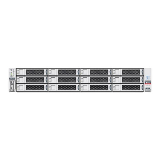
Page 17: Front Panel Components
Fault-Service Required LED: Rear: Power Supply (amber) Fault-Service Required LED: Overtemp Icon: System Over Temperature Warning (amber) SP OK LED: green DO NOT SERVICE LED: white Storage drive 0 HDD/SSD/NVMe Storage drive 1 HDD/SSD/NVMe Storage drive 2 HDD/SSD/NVMe About the Oracle Server X7-2L... -
Page 18: Back Panel Components And Cable Connections
Power Supply (PS) 1 status indicators: Fault-Service Required LED: amber; AC OK LED: green Power supply (PS 0) Power Supply (PS) 0 status indicators: Fault-Service Required LED: amber; AC OK LED: green Oracle Server X7-2L Service Manual • October 2017... -
Page 19: About System Components
PCIe slot 5 (Nonfunctional in single-processor systems) PCIe slot 6 Serial management (SER MGT) RJ-45 serial port Oracle Integrated Lights Out Manager (ILOM) service processor (SP) network management (NET MGT) RJ-45 10/100/1000BASE-T port Network (NET) 100/1000BASE-T RJ-45 Gigabit Ethernet (GbE) port: NET 0 USB 3.0 connector... -
Page 20: Illustrated Parts Breakdown
Fan tray Motherboard assembly Processors and heatsinks (Single-processor systems contain only a single processor in socket P0; socket P1 contains a cover to protect processor socket pins.) Internal M.2 flash SSDs Top cover Oracle Server X7-2L Service Manual • October 2017... -
Page 21: Customer-Replaceable Units
About System Components Figure Description Legend (Optional) Oracle Storage 12 Gb SAS PCIe RAID HBA, Internal card and super capacitor PCIe cards (PCIe slots 1 through 6 are nonfunctional in single-processor systems.) System battery (Optional) Internal USB drive Power supplies... -
Page 22: Field-Replaceable Units
“Servicing NVMe Cables switch cards and the disk backplane. (FRU)” on page 193 Oracle Storage 12 Located in PCIe slot 11, the Oracle Storage 12 Gb “Servicing the Internal HBA Gb SAS PCIe RAID SAS PCIe RAID HBA, Internal card manages SAS... -
Page 23: Troubleshooting And Diagnostics
When a server hardware fault event occurs, the system lights the Fault-Service Required LED and captures the event in the system event log (SEL). If you set up notifications through Oracle ILOM, you also receive an alert through the notification method you chose. When you become aware of a hardware fault, address it immediately. - Page 24 Oracle Service personnel. Contact Oracle Service. 6. Clear the fault in Oracle ILOM. Depending on the component, you might need to clear the fault in Oracle ILOM. Generally, components that have a FRU ID clear the fault automatically. Related Information “Troubleshoot Hardware Faults Using the Oracle ILOM Web Interface”...
- Page 25 This procedure uses the basic troubleshooting steps described in “Basic Troubleshooting Process” on page Use this procedure to troubleshoot hardware faults using the Oracle ILOM web interface and, if necessary, prepare the server for service. This procedure provides one basic approach to troubleshooting hardware faults. It uses Note - the Oracle ILOM web interface.
- Page 26 Troubleshoot Hardware Faults Using the Oracle ILOM Web Interface In the following example, the Status page shows that the Processor subsystem requires service, which indicates that a hardware component in the subsystem is in a fault state. To identify the component, click the Processors in the Status section.
-
Page 27: Troubleshooting And Diagnostic Information
To prepare the server for service, see “Preparing for Service” on page After servicing the component, you might need to clear the fault in Oracle ILOM. For more information, refer to the service procedure for the component. Service the component. -
Page 28: Troubleshooting Using The Server Front And Back Panel Status Indicators
2. After a few minutes, the main System OK LED slowly flashes the standby blink pattern (0.1 seconds on, 2.9 seconds off), indicating that the SP (and Oracle ILOM) is ready for use. In Standby power mode, the server is not initialized or fully powered on at this point. -
Page 29: Server System-Level Status Indicators
System OK Green Indicates the operational state of the chassis. ■ OFF – AC power is not present or the Oracle ILOM boot is not complete. ■ STANDBY BLINK – Standby power is on, but the chassis power is off and the Oracle ILOM SP is running. -
Page 30: Server Fan Status Indicators
Troubleshoot Hardware Faults Using the Oracle ILOM Web Interface Status Indicator Icon Color State and Meaning Name host is booting the operating system (OS), or the server host is running the OS. SP OK Green Indicates the state of the service processor. -
Page 31: Storage Drive Status Indicators
Troubleshoot Hardware Faults Using the Oracle ILOM Web Interface Status Indicator Icon Color State and Meaning Name Fan Status Amber ■ Off – The fan module is correctly installed and operating within specification. ■ Amber – The fan module is faulty. The front TOP... -
Page 32: Network Management Port Status Indicators
Troubleshoot Hardware Faults Using the Oracle ILOM Web Interface Status Indicator Icon Color State and Meaning Name ■ SLOW BLINK – Normal operation. Input power is within specification. DC output voltage is not enabled. ■ STEADY ON – Normal operation. Input AC power and DC output voltage are within specification. -
Page 33: Troubleshooting System Cooling Issues
■ Each of the 24 DIMM sockets on the motherboard has an amber fault status indicator Indicators (LED) associated with it. ■ If Oracle ILOM determines that a DIMM is faulty, pressing the Fault Remind button on the motherboard I/O card signals the service processor to light the fault LED associated with the failed DIMM. - Page 34 Troubleshoot Hardware Faults Using the Oracle ILOM Web Interface Cooling Issue Description Action Prevention Temperature environment. If the ambient environmental specifications to ensure that it is within the Too High temperature is too high, the for the server. If the...
-
Page 35: Troubleshooting Power Issues
Troubleshoot Hardware Faults Using the Oracle ILOM Web Interface Cooling Issue Description Action Prevention ■ To reduce the risk related to component failure, power supplies and fan modules are installed in pairs to provide redundancy. Redundancy ensures that if one component in... -
Page 36: Managing Server Hardware Faults Through The Oracle Ilom Fault Management Shell
The Oracle ILOM Fault Management Shell enables Oracle Service personnel to view and manage fault activity on managed servers and other types of devices. For more information about how to use the Oracle ILOM Fault Management Shell, see the Oracle ILOM User's Guide for System Monitoring and Diagnostics Firmware Release 4.0.x in... -
Page 37: Troubleshooting With Diagnostic Tools
Oracle Integrated Lights Out Manager (ILOM) 4.0 Documentation Library at http://www. oracle.com/goto/ilom/docs. The purpose of the Oracle ILOM Fault Management Shell is to help Oracle Service Caution - personnel diagnose system problems. Customers must not launch this shell or run fault management commands in the shell unless requested to do so by Oracle Service. -
Page 38: Diagnostic Tool Documentation
Diagnostic Tool Documentation The following table identifies where you can find more information about diagnostic tools. Diagnostic Tool Documentation Location Oracle ILOM Oracle Integrated Lights Out http://www.oracle.com/goto/ Manager 4.0 Documentation Library ilom/docs Oracle Server X7-2L Service Manual • October 2017... -
Page 39: Attaching Devices To The Server
Connect an Ethernet cable to the Gigabit Ethernet (NET) connector as needed for OS support. “Back Panel Connector Locations” on page To connect to the service processor's Oracle ILOM over the network, connect an Ethernet cable to the Ethernet port labeled NET MGT. “Back Panel Connector Locations” on page To access the Oracle ILOM command-line interface (CLI) locally, connect a serial null modem cable to the RJ-45 serial port labeled SER MGT. -
Page 40: Back Panel Connector Locations
Do not attach power cables to the power supplies until you finish connecting the data cables to the server. The server goes into Standby power mode, and the Oracle ILOM service processor initializes when the AC power cables are connected to the power source. -
Page 41: Configuring Serial Port Sharing
By default, the SP console (SER MGT) port sends serial port output from the server. Using Oracle ILOM, you can specify that the host console (COM1) be assigned as owner of the server serial port output. This feature is useful for Windows kernel debugging, as it enables you to view non-ASCII character traffic from the host console. - Page 42 Assign Serial Port Output Using the Oracle ILOM CLI Assign Serial Port Output Using the Oracle ILOM CLI Open an SSH session, and at the command line, log in to the SP Oracle ILOM CLI. Log in as a user with root or administrator privileges. For example:...
-
Page 43: Server Operating System Names For The Nvme Storage Drives
The drive names provided in the table assume that: Oracle PCIe NVMe switch cards are installed in PCIe slots 3, 4, 8, and 9 ■ NVMe cabling between the Oracle PCIe NVMe switch cards and the disk backplane is ■... -
Page 44: Back Panel Pinhole Switches
Assign Serial Port Output Using the Oracle ILOM Web Interface Ethernet Port Device Naming The device naming for the Ethernet interface is reported differently by different interfaces and operating systems. The following table shows the BIOS (physical) and operating system (logical) naming convention for the interface. -
Page 45: Getting Help
† (NMI) Host Warm Reset SP Reset † Oracle Service use only. Getting Help The following sections describe how to get additional help to resolve server-related problems. “Contacting Support” on page 46 ■ “Locating the Chassis Serial Number” on page 46 ■... -
Page 46: Contacting Support
You might need your server serial number when you ask for service on your system. Record this number for future use. Use one of the following resources or methods to locate your server serial number. Oracle Server X7-2L Service Manual • October 2017... -
Page 47: Auto Service Requests
Oracle Auto Service Requests (ASR) is a feature available to customers having Oracle Premier Support and is provided to those customers at no additional cost. Oracle ASR is the fastest way to restore system availability if a hardware fault occurs. Oracle ASR software is secure and customer installable, with the software and documentation downloadable from My Oracle Support at https://support.oracle.com. - Page 48 Oracle Server X7-2L Service Manual • October 2017...
-
Page 49: Preparing For Service
Follow all standard cautions, warnings, and instructions marked on the equipment and ■ described in the Oracle Server X7-2L Safety and Compliance Guide and Important Safety Information for Oracle's Hardware Systems. Ensure that the voltage and frequency of your power source match the voltage and ■... -
Page 50: Safety Symbols
When servicing or removing server components, disconnect the power cords from the server and then attach an antistatic strap to your wrist and then to a metal area on the Oracle Server X7-2L Service Manual • October 2017... -
Page 51: Fru Key Identity Properties (Kip) Automated Update
■ FRU Key Identity Properties (KIP) Automated Update Oracle ILOM includes a key identity properties (KIP) auto-update feature that ensures product information that is used for service entitlement and warranty coverage is accurately maintained by the server at all times, including during hardware replacement activities. -
Page 52: Required Tools
Required Tools When a server FRU that contains the KIP is removed and a replacement component is installed, the KIP of the replacement component is programmed by Oracle ILOM to contain the same KIP as the other two components. Only one of the quorum members can be replaced at a time. Automated updates can only Note - be completed when two of the three quorum members contain matching key identity properties. -
Page 53: Powering Down The Server
If the server is not responding, or you must shut down ■ “Power Down the Server for Immediate Shutdown the server quickly, perform an immediate shutdown. Using the Oracle ILOM CLI” on page 57 ■ “Power Down the Server for Immediate Shutdown Using the Oracle ILOM Web Interface”... - Page 54 “Power Down the Server for Immediate Shutdown Using the Oracle ILOM CLI” on page If the system is running the Oracle Solaris OS, refer to the Oracle Solaris system administration documentation for additional information. Disconnect the power and cables from the server.
- Page 55 Power Down the Server Gracefully Using the Oracle ILOM Web Interface Related Information “Power Down the Server Gracefully Using the Oracle ILOM Web Interface” on page 55 ■ “Power Down the Server Gracefully Using the On/Standby Button” on page 56 ■...
- Page 56 “Server System-Level Status Indicators” on page 29 ■ “Power Down the Server Gracefully Using the Oracle ILOM CLI” on page 54 ■ “Power Down the Server Gracefully Using the Oracle ILOM Web Interface” on page 55 ■ “Power On the Server” on page 216 ■...
- Page 57 Log in to the Oracle ILOM command-line interface (CLI) using an Administrator account. Oracle ILOM displays the default command prompt (->), indicating that you have successfully logged in to Oracle ILOM. From the CLI prompt, type the following command: ->...
- Page 58 Disconnect the power and data cables from the server. “Disconnect Cables From the Server” on page When you power down the server using Oracle ILOM, the server enters Standby Caution - power mode. Power is still directed to the service processor and power supply fans. To completely power off the server, you must disconnect the power cords from the power supplies.
-
Page 59: Disconnect Cables From The Server
“Power Down the Server for Immediate Shutdown Using the Oracle ILOM ■ CLI” on page 57 “Power Down the Server for Immediate Shutdown Using the Oracle ILOM Web ■ Interface” on page 57 “Power On the Server” on page 216 ■... -
Page 60: Extend The Server To The Maintenance Position
To prevent the rack from tipping forward when the server is extended, extend all rack anti-tilt mechanisms. Refer to “Stabilize the Rack” in Oracle Servers X7-2 and X7-2L Installation Guide. Verify that no cables will be damaged or will interfere when the server is extended. -
Page 61: Remove The Server From The Rack
Remove the Server From the Rack Deploy any rack anti-tilt mechanism before releasing the slide-rail release latches. Caution - While the release latch covers are in the open position, slowly pull the server forward until the slide-rails latch into a locked position [2]. The server is now in the extended maintenance position. -
Page 62: Take Antistatic Measures
Take Antistatic Measures Remove the cable management arm (CMA). Refer to “Remove the Cable Management Arm” in Oracle Servers X7-2 and X7-2L Installation Guide. Extend the server to the maintenance position. “Extend the Server to the Maintenance Position” on page... -
Page 63: Remove The Server Top Cover
Remove the Server Top Cover An antistatic bag used to wrap a replacement part ■ An Oracle ESD mat (orderable item) ■ A disposable ESD mat (shipped with some replacement parts or optional system ■ components) Attach an antistatic wrist strap. - Page 64 Lift up on the release button on top of the server cover. Lifting the release button causes the server cover to slide toward the rear of the chassis for easy removal. Lift up and remove the top cover [2]. Oracle Server X7-2L Service Manual • October 2017...
- Page 65 Remove the Server Top Cover Related Information “Take Antistatic Measures” on page 62 ■ “Install the Server Top Cover” on page 212 ■ Preparing for Service...
- Page 66 Oracle Server X7-2L Service Manual • October 2017...
-
Page 67: Servicing Storage Drives (Cru)
“Storage Drive Locations and Numbering” on page 68 ■ “Removing and Replacing a Storage Drive” on page 69 ■ “Removing and Replacing an NVMe Storage Drive Using Oracle Solaris” on page 74 ■ “Removing and Replacing an NVMe Storage Drive Using Oracle Linux” on page 77 ■... -
Page 68: Storage Drive Failure And Raid
“Storage Drive Status Indicators” on page 31 ■ “Removing and Replacing a Storage Drive” on page 69 ■ “Removing and Replacing an NVMe Storage Drive Using Oracle Solaris” on page 74 ■ “Removing and Replacing an NVMe Storage Drive Using Oracle Linux” on page 77 ■... -
Page 69: Removing And Replacing A Storage Drive
Removing and Replacing a Storage Drive Callout Description Storage drive 0 HDD/SSD/NVMe Storage drive 4 HDD/SSD/NVMe Storage drive 8 HDD/SSD/NVMe Storage drive 1 HDD/SSD/NVMe Storage drive 5 HDD/SSD/NVMe Storage drive 9 HDD/SSD/NVMe Storage drive 2 HDD/SSD/NVMe Storage drive 6 HDD/SSD/NVMe Storage drive 10 HDD/SSD/NVMe Storage drive 3 HDD/SSD/NVMe Storage drive 7 HDD/SSD/NVMe... -
Page 70: Remove A Storage Drive
NVMe storage drives are supported only on servers that are running Oracle Solaris, Note - Oracle Linux, Oracle VM, or Microsoft Windows Server. Servers that are running Red Hat Enterprise Linux do not support NVMe drives. “Removing and Replacing an NVMe Storage Drive Using Oracle ■... - Page 71 Remove a Storage Drive On the drive that you plan to remove, push the latch release button to open the drive latch [1, 2]. Callout Description Pressing the latch release button. Opening the latch. The latch is not an ejector. Do not open the latch too far to the right. Doing so can Caution - damage the latch.
-
Page 72: Install A Storage Drive
“Storage Drive Failure and RAID” on page 68 ■ “Install a Storage Drive” on page 72 ■ Install a Storage Drive Remove the replacement drive from its packaging, and place the drive on an antistatic mat. Oracle Server X7-2L Service Manual • October 2017... - Page 73 Install a Storage Drive If necessary, remove the drive filler panel. Align the replacement drive with the drive slot. The drive is physically addressed according to the slot in which it is installed. It is important to install a replacement drive in the same slot as the drive that was removed. Slide the drive into the slot until the drive is fully seated.
-
Page 74: Removing And Replacing An Nvme Storage Drive Using Oracle Solaris
“Power On an NVMe Storage Drive and Attach a Device Driver” on page 76 ■ Unmount an NVMe Storage Drive Log in to Oracle Solaris that is running on the server. To find the NVMe drive slot number, type: hotplug list –lc... -
Page 75: Remove An Nvme Storage Drive
Remove an NVMe Storage Drive Remove an NVMe Storage Drive Perform this procedure to physically remove an NVMe storage drive from the server. Identify the physical location of the NVMe drive that you want to remove. For storage drive locations, see “Remove a Storage Drive”... -
Page 76: Power On An Nvme Storage Drive And Attach A Device Driver
To check the NVMe drive health, firmware level, temperature, get error log, SMART data, security erase, low level format, and other data, type: nvmeadm list Related Information “Storage Drive Status Indicators” on page 31 ■ “Storage Drives Hot-Plug Conditions” on page 67 ■ Oracle Server X7-2L Service Manual • October 2017... -
Page 77: Removing And Replacing An Nvme Storage Drive Using Oracle Linux
“Verify Operation of an NVMe Storage Drive” on page 81 ■ Unmount an NVMe Storage Drive Log in to Oracle Linux that is running on the server. Remove the NVMe storage device path. To find the PCIe addresses (Bus Device Function), type: find /sys/devices |egrep ‘nvme[0-9][0-9]?$’... -
Page 78: Oracle Server X7-2L Service Manual • October
Run the blockdev --flushbufs device command to flush any outstanding I/O to all paths to the device. To prepare the NVMe drive for removal, that is, to detach the NVMe device driver and power off the NVMe drive slot, type: Oracle Server X7-2L Service Manual • October 2017... -
Page 79: Remove An Nvme Storage Drive
Remove an NVMe Storage Drive echo 0 > /sys/bus/pci/slots/$slot/power Where $slot is the slot number obtained in step Step 2b above. Verify that the OK to Remove indicator (LED) on the NVMe drive is lit. Remove an NVMe Storage Drive Perform this procedure to physically remove an NVMe storage drive from the server. -
Page 80: Install An Nvme Storage Drive
Power On an NVMe Storage Drive and Attach a Device Driver To power on the slot and attach the device driver, type: echo 1 /sys/bus/pci/slots/$slot/power Where $slot is the slot number for the NVMe storage drive. Oracle Server X7-2L Service Manual • October 2017... -
Page 81: Verify Operation Of An Nvme Storage Drive
The following sections describe how to remove and replace an NVMe storage drive on a server that is running the Microsoft Windows Server operating system. NVMe storage drive hot plug is not supported for an Oracle Server X7-2L running Note - Microsoft Windows Server. -
Page 82: Install An Nvme Storage Drive
“Power On the Server” on page 216. Verify that the power supply AC OK LED is lit. Related Information “Storage Drive Status Indicators” on page 31 ■ “Storage Drives Hot-Plug Conditions” on page 67 ■ Oracle Server X7-2L Service Manual • October 2017... - Page 83 Install an NVMe Storage Drive “Storage Drive Failure and RAID” on page 68 ■ “Remove a Storage Drive” on page 70 ■ “Install a Storage Drive” on page 72 ■ Servicing Storage Drives (CRU)
- Page 84 Oracle Server X7-2L Service Manual • October 2017...
-
Page 85: Servicing Fan Modules (Cru)
Oracle ILOM. Even if only one fan motor is faulted within the fan module, the Oracle ILOM service processor detects that two fan motors have failed to spin while the fan module is removed. If the fan module is not replaced within 20 seconds of removal, Oracle ILOM will take the protective action to shut down the system to prevent thermal damage to the system. - Page 86 Amber – The fan module is faulty. The front Top Fan LED and the front and back panel Fault-Service Required LEDs are also lit if the system detects a fan module fault. Oracle Server X7-2L Service Manual • October 2017...
-
Page 87: Install A Fan Module
Install a Fan Module Using your forefinger and thumb, lift the fan module straight up and out of the chassis and set it aside on an antistatic mat. Consider your next step: If you removed the fan assembly as part of another procedure, return to that procedure. ■... - Page 88 If you installed the fan module as part of another procedure, return to that procedure. ■ Otherwise, return the server to operation. See “Returning the Server to ■ Operation” on page 211. Related Information “Remove a Fan Module” on page 85 ■ Oracle Server X7-2L Service Manual • October 2017...
-
Page 89: Remove The Fan Tray
Remove the Fan Tray Remove the Fan Tray This procedure should be performed only when servicing the following field-replaceable units (FRUs): Disk backplane ■ SAS cables ■ NVMe cables ■ Temperature sensor ■ Motherboard assembly ■ Using a Torx T25 screwdriver, loosen the three spring-mounted screws that secure the fan tray to the server chassis [1]. -
Page 90: Install The Fan Tray
“Servicing the Motherboard Assembly (FRU)” on page 199 ■ Install the Fan Tray This procedure should be performed only when servicing the following field-replaceable units (FRUs): Disk backplane ■ SAS cables ■ NVMe cables ■ Motherboard assembly ■ Oracle Server X7-2L Service Manual • October 2017... - Page 91 Install the Fan Tray Lower the fan tray into the server [1]. Using a Torx T25 screwdriver, tighten the three spring-mounted screws that secure the fan tray to the server chassis [2]. Continue with the next step in the service procedure. Related Information “Install a Fan Module”...
- Page 92 Oracle Server X7-2L Service Manual • October 2017...
-
Page 93: Servicing Power Supplies (Cru)
Servicing Power Supplies (CRU) This section describes how to service power supplies. Power supplies are customer-replaceable units (CRUs) that do not require you to power off the server. For more information about CRUs, “Illustrated Parts Breakdown” on page 20 “Customer-Replaceable Units” on page The power supplies are located at the back of the server. -
Page 94: Remove A Power Supply
“Troubleshooting Using the Server Front and Back Panel Status Indicators” on page 28 ■ Remove a Power Supply Prepare the system for power supply removal. Refer to “Take Antistatic Measures” on page Identify which power supply requires replacement. Oracle Server X7-2L Service Manual • October 2017... - Page 95 (->) to identify a power supply failure. Alternatively, to list all known faults in the server, log in to the Oracle Solaris OS and issue the fmadm faulty command, or log in to the Oracle ILOM service processor from the Oracle ILOM Fault Management Shell and issue the fmadm faulty command.
-
Page 96: Install A Power Supply
“Power Supply Status Indicators” on page 31 ■ “Install a Power Supply” on page 96 ■ Install a Power Supply Always replace the failed power supply with the same type model of power supply. Caution - Oracle Server X7-2L Service Manual • October 2017... - Page 97 Verify that the amber Fault-Service Required LED on the replaced power supply and the Fault-Service Required LEDs are not lit on the front and back panels. After you have replaced Power Supply 0, you might need to reset the Oracle ILOM Note - service processor (SP) to propagate the key identity properties (KIP) data to the new power supply.
- Page 98 Install a Power Supply Refer to “Install the Cable Management Arm (Optional)” in Oracle Servers X7-2 and X7-2L Installation Guide. Related Information “Back Panel Components and Cable Connections” on page 18 ■ “Power Supply Status Indicators” on page 31 ■...
-
Page 99: Servicing The Internal M.2 Flash Ssds (Cru)
Servicing the Internal M.2 Flash SSDs (CRU) This section describes how to service M.2 flash solid-state drives (SSDs). M.2 flash SSDs are customer-replaceable units (CRUs) that do not require you to power off the server. For more information about CRUs, see “Illustrated Parts Breakdown”... - Page 100 Place the riser board on an antistatic mat. If required, perform the procedures for removing the M.2 flash SSD from the flash riser board. See “Identify and Remove a Faulty M.2 Flash SSD” on page 103. Oracle Server X7-2L Service Manual • October 2017...
-
Page 101: Install A Flash Riser Board
Install a Flash Riser Board Related Information “Install a Flash Riser Board” on page 101 ■ Install a Flash Riser Board The system motherboard provides two slots (labeled M.2 R 0 and M.2 R 1) for flash riser boards. When installing flash riser boards, install the first riser board into slot M.2 R 0 and then into M.2 R 1. - Page 102 “Install the Server Top Cover” on page 212. Return the server to the normal rack position. “Return the Server to the Normal Rack Position” on page 214. Related Information “Remove a Flash Riser Board” on page 99 ■ Oracle Server X7-2L Service Manual • October 2017...
-
Page 103: Identify And Remove A Faulty M.2 Flash Ssd
Identify and Remove a Faulty M.2 Flash SSD Identify and Remove a Faulty M.2 Flash SSD Prepare the server for service. Extend the server into maintenance position. “Extend the Server to the Maintenance Position” on page Attach an antistatic wrist strap to your wrist, and then to a metal area on the chassis. - Page 104 Gently slide the M.2 flash SSD card rearward and out of the connector to disengage the SSD contacts from the riser board socket. Place the M.2 flash SSD on an antistatic mat. Related Information “Install an M.2 Flash SSD” on page 105 ■ Oracle Server X7-2L Service Manual • October 2017...
-
Page 105: Install An M.2 Flash Ssd
Install an M.2 Flash SSD Install an M.2 Flash SSD The M.2 flash SSD should be installed only in the socket labeled SSD0. Note - Unpack the replacement M.2 flash SSD. Install the M.2 flash SSD. Align and then insert the plastic retainer clip into the slot on the M.2 flash SSD. - Page 106 Return the server to the normal rack position. “Return the Server to the Normal Rack Position” on page 214. Related Information “Identify and Remove a Faulty M.2 Flash SSD” on page 103 ■ Oracle Server X7-2L Service Manual • October 2017...
-
Page 107: Servicing An Internal Usb Flash Drive (Cru)
Servicing an Internal USB Flash Drive (CRU) This section describes how to service a USB flash drive. The USB flash drive is a customer- replaceable unit (CRU) that requires you to power off the server. For more information about CRUs, see “Illustrated Parts Breakdown”... -
Page 108: Install An Internal Usb Flash Drive
To remove a USB flash drive, grasp the flash drive and pull it from the slot. Related Information “Install an Internal USB Flash Drive” on page 108 ■ Install an Internal USB Flash Drive Unpack the replacement USB flash drive. Oracle Server X7-2L Service Manual • October 2017... - Page 109 Install an Internal USB Flash Drive Insert the flash drive into the USB slot. Return the server to operation. Install the server top cover. “Install the Server Top Cover” on page 212. Return the server to the normal rack position. “Return the Server to the Normal Rack Position”...
- Page 110 Oracle Server X7-2L Service Manual • October 2017...
-
Page 111: Servicing The Air Baffle (Cru)
Servicing the Air Baffle (CRU) This section describes how to service the air baffle. The air baffle is a customer-replaceable unit (CRU) that requires you to power off the server. For more information about CRUs, see “Illustrated Parts Breakdown” on page 20 “Customer-Replaceable Units”... - Page 112 Remove the server top cover. “Remove the Server Top Cover” on page Release the latch for the host bus adapter (HBA) super capacitor tray and rotate the tray [1] in to the upright position [2]. Oracle Server X7-2L Service Manual • October 2017...
-
Page 113: Install The Air Baffle
Install the Air Baffle Remove the air baffle by lifting the baffle up and out of the server. Set aside the air baffle. Consider your next step: If you removed the air baffle as part of another procedure, return to that procedure. ■... - Page 114 Install the Air Baffle Install the air baffle by placing it into the server and lowering it to its inserted position. Rotate the HBA super capacitor tray down and in to its closed position. Oracle Server X7-2L Service Manual • October 2017...
- Page 115 Install the Air Baffle You will hear an audible click when the tray is properly secured to the air baffle. Consider your next step: If you removed the air baffle as part of another procedure, return to that procedure. ■ Otherwise, continue to with this procedure.
- Page 116 Install the Air Baffle Related Information “Remove the Air Baffle” on page 111 ■ Oracle Server X7-2L Service Manual • October 2017...
-
Page 117: Servicing The Dimms (Cru)
“Illustrated Parts Breakdown” on page 20 “Customer-Replaceable Units” on page The Oracle Server X7-2L supports a variety of DDR4 DIMM configurations that can include quad-rank (QR) and dual-rank (DR) DDR4 DIMMs. These procedures require that you handle components that are sensitive to Caution - electrostatic discharge. -
Page 118: Dimm And Processor Physical Layout
0 (P0) is on the left. In single-processor systems, the DIMM sockets associated with processor 1 (P1) are Note - nonfunctional and should not be populated with DIMMs. Related Information “DIMM Population Scenarios” on page 119 ■ Oracle Server X7-2L Service Manual • October 2017... -
Page 119: Dimm Population Scenarios
DIMM Population Scenarios “DIMM Population Rules” on page 119 ■ “Populating DIMMs for Optimal System Performance” on page 120 ■ “DIMM Operating Speeds” on page 123 ■ “DIMM Rank Classification Labels” on page 123 ■ “Inconsistencies Between DIMM Fault Indicators and the BIOS Isolation of Faulty ■... -
Page 120: Populating Dimms For Optimal System Performance
In single-processor systems, install DIMMs only into DIMM sockets associated with processor 0 (P0). Starting with socket P0 D7, first fill the black sockets, and then fill the white sockets, as shown in the following figure. Oracle Server X7-2L Service Manual • October 2017... - Page 121 Populating DIMMs in Single-Processor Systems for Optimal System Performance The following table describes the proper order in which to populate DIMMs in a single- processor system using the numbered callouts in the above figure, and the DIMM socket labels (D0 through D11). Population Order Processor/DIMM Slot Populate black slots first in the following order:...
-
Page 122: Populating Dimms In Dual-Processor Systems For Optimal System Performance
D11). Population Order Processor/DIMM Slot Populate black slots first in the following order: 1. P0/D7 2. P1/D7 3. P0/D4 4. P1/D4 5. P0/D9 6. P0/D2 7. P1/D9 8. P1/D2 9. P0/D11 Oracle Server X7-2L Service Manual • October 2017... -
Page 123: Dimm Operating Speeds
DIMM Operating Speeds Population Order Processor/DIMM Slot 10. P0/D0 11. P1/D11 12. P1/D0 After black slots have been populated, populate white 1. P0/D6 slots in the following order: 2. P1/D6 3. P0/D5 4. P1/D5 5. P0/D8 6. P0/D3 7. P1/D8 8. -
Page 124: Dimms
Inconsistencies Between DIMM Fault Indicators and the BIOS Isolation of Faulty DIMMs When a single DIMM is marked as failed by Oracle ILOM (for example, fault.memory. intel.dimm.training-failed is listed in the service processor Event Log), BIOS might disable the entire memory channel that contains the failed DIMM, up to two DIMMs. As a result, none of the memory installed in the disabled channel will be available to the operating system. -
Page 125: Identify And Remove A Faulty Dimm
Identify and Remove a Faulty DIMM Identify and Remove a Faulty DIMM Prepare the server for service. Power off the server, and disconnect the power cords from the server power supplies. “Powering Down the Server” on page Extend the server into the maintenance position. “Extend the Server to the Maintenance Position”... - Page 126 If the DIMM Fault LED is on (amber), then the DIMM is faulty and should be replaced [1]. ■ To remove the faulty DIMM, do the following: Rotate both DIMM socket ejectors outward as far as they will go. The DIMM is partially ejected from the socket. Oracle Server X7-2L Service Manual • October 2017...
-
Page 127: Install A Dimm
Install a DIMM Carefully lift the DIMM straight up to remove it from the socket. Replace each faulty DIMM with either another DIMM of the same rank size (quad- rank or dual-rank) or leave the socket empty. For DIMM replacement instructions, see “Install a DIMM”... - Page 128 DIMM is aligned with the connector key in the connector socket. If the notch is not aligned, damage to the DIMM might occur. Repeat Step 3 until all replacement DIMMs are installed. Return the server to operation: Oracle Server X7-2L Service Manual • October 2017...
- Page 129 (Optional) Use Oracle ILOM to clear server DDR4 DIMM faults. DDR4 DIMM faults are automatically cleared after a new DIMM has been installed. If you need to manually clear DDR4 DIMM faults, refer to the Oracle Integrated Lights Out Manager (ILOM) 4.0 Documentation Library at http://www.oracle.com/goto/ilom/docs.
- Page 130 Oracle Server X7-2L Service Manual • October 2017...
-
Page 131: Servicing Pcie Cards (Cru)
12 Gb SAS PCIe RAID HBA, Internal card that is located in PCIe slot 11 or the Oracle PCIe NVMe switch cards that are located in PCIe slots 3, 4, 8, and 9. The Oracle Storage 12 Gb SAS PCIe RAID HBA, Internal card and Oracle PCIe NVMe switch cards are field-replaceable units (FRUs) and should be serviced only by authorized Oracle Service personnel. -
Page 132: Pcie Slot Locations
PCIe slot 8 (Primary slot for Oracle PCIe NVMe switch card.) PCIe slot 9 (Primary slot for Oracle PCIe NVMe switch card.) PCIe slot 10 PCIe slot 11 (Primary slot for the Oracle Storage 12 Gb SAS PCIe RAID HBA, Internal card) Oracle Server X7-2L Service Manual • October 2017... -
Page 133: Remove A Pcie Card
Remove a PCIe Card All of the PCIe slots comply with the PCI Express 3.0 specification and can Note - accommodate 25 Watt PCIe3 cards. Related Information “Remove a PCIe Card” on page 133 ■ “Install a PCIe Card” on page 135 ■... - Page 134 If you are not immediately inserting a replacement PCIe card into the empty slot, Caution - insert a PCIe filler panel in the slot to reduce the possibility of radiated electromagnetic interference (EMI). See “Remove and Install Filler Panels” on page 212. Oracle Server X7-2L Service Manual • October 2017...
-
Page 135: Install A Pcie Card
Unpack the replacement PCIe card, and place it on an antistatic mat. Locate the proper PCIe slot for the card you are replacing. PCIe slots 3, 4, 8, and 9 are the primary slots for Oracle PCIe NVMe switch cards. These Note - cards are required for controlling and managing the optional NVMe storage drives. - Page 136 Step 3 “Install NVMe Cables” on page 196. To ensure proper SAS cable connections for Oracle Storage 12 Gb SAS PCIe HBA, Internal cards, see the SAS cabling reference table in Step 3 “Install SAS Storage Drive Cables” on page 190.
- Page 137 216. Verify that the AC OK LED is lit. Use Oracle ILOM to clear any server PCIe card faults. If a PCIe card fault message in Oracle ILOM is not cleared under Open Problems, you must manually clear the fault using Oracle ILOM. For instructions for manually clearing a PCIe card fault, see the procedure "Clear Faults for Undetected Replaced or Repaired...
- Page 138 Oracle Server X7-2L Service Manual • October 2017...
-
Page 139: Servicing The Battery (Cru)
Servicing the Battery (CRU) This section describes how to service the system battery. The system battery is a customer- replaceable unit (CRU) that requires you to power off the server. For more information about CRUs, see “Illustrated Parts Breakdown” on page 20 “Customer-Replaceable Units”... - Page 140 “Servicing the Disk Backplane (FRU)” on page 157 “Servicing SAS Cables (FRU)” on page 187. Lift the battery up and out of its retainer. Related Information “Install the Battery” on page 141 ■ Oracle Server X7-2L Service Manual • October 2017...
-
Page 141: Install The Battery
If the service processor is configured to synchronize with a network time server using Note - the Network Time Protocol (NTP), the Oracle ILOM SP clock will be reset as soon as the server is powered on and connected to the network; otherwise, proceed to the next step. - Page 142 Oracle Server X7-2L Service Manual • October 2017...
-
Page 143: Servicing Processors (Fru)
Caution - processor. You must disconnect the power cables from the system before performing these procedures. Processors must be removed and replaced only by authorized Oracle Service Caution - personnel. This procedure requires that you handle components that are sensitive to electrostatic Caution - discharge. -
Page 144: Identify And Remove A Faulty Processor
Remind button, it is likely that the capacitor powering the fault remind circuit lost its charge. This can happen if you press the Fault Remind button for a long time with fault LEDs lit, or if power was removed from the server for more than 15 minutes. Oracle Server X7-2L Service Manual • October 2017... - Page 145 Identify and Remove a Faulty Processor The processor fault LED for the faulty processor lights. The processor fault LEDs are located next to the processors: If the processor fault LED is off, then the processor is operating properly. ■ If the processor fault LED is on (amber), then the processor is faulty and must be replaced. ■...
- Page 146 4, then 3, then 2, then 1. [1] Lift the processor-heatsink module from the socket [2]. Always hold the processor-heatsink module along the axis of the fins to prevent damage. Separate the processor from the heatsink. Oracle Server X7-2L Service Manual • October 2017...
- Page 147 Identify and Remove a Faulty Processor Flip over the processor-heatsink module, place it on a flat surface, and locate the thermal interface material (TIM) breaker slot. While holding down the processor-heatsink module by the edges, insert a flat blade screwdriver into the TIM breaker slot. Servicing Processors (FRU)
- Page 148 The blade of the screwdriver goes into the slot between the heatsink and processor carrier, not between the processor and processor carrier. Using a rocking motion, gently pry the corner of the processor carrier away from the heatsink. Oracle Server X7-2L Service Manual • October 2017...
- Page 149 Identify and Remove a Faulty Processor Remove the processor carrier with processor from the heatsink by prying or pinching the plastic latch tabs that attach the processor to the heatsink. A thin layer of thermal grease separates the heatsink and the processor. This grease Note - acts as an adhesive.
-
Page 150: Install A Processor
Distribute the thermal grease over the square heatsink-to-processor contact area using a flat-edged tool [2]. Ensure that you spread thermal grease evenly on the contact areas. Note - Install the new processor. Oracle Server X7-2L Service Manual • October 2017... - Page 151 Install a Processor Align the pin 1 indicators between the heatsink and processor carrier in the packaging tray, and place the heatsink (thermal side down) onto the processor carrier until it snaps in place and lies flat. The processor carrier has latching posts at each corner: two that insert into heatsink holes Note - and two that attach to the edge of the heatsink.
- Page 152 Align the processor-heatsink module to the processor socket bolster plate on the motherboard, matching the pin 1 location (a triangle indicator). Callout Description Pin 1 indicator Place the processor-heatsink module on the socket on the motherboard. Oracle Server X7-2L Service Manual • October 2017...
- Page 153 Install a Processor The socket bolster plate has alignment pins that go into holes on the processor-heatsink module to help center the module during installation. Ensure that the processor-heatsink module lies evenly on the bolster plate and that the captive screws align with the threaded socket posts [1]. Using a 12.0 in-lbs/ft (inch-pounds/foot) torque driver (part number 7352217) with a Torx T30 bit, tighten the processor-heatsink module to the socket.
- Page 154 Refer to the Oracle Integrated Lights Out Manager (ILOM) 4.0 Documentation Library at for more information about the following steps. http://www.oracle.com/goto/ilom/docs To show server faults, log in to the server as root using the Oracle ILOM CLI, and type the following command to list all known faults on the server: ->...
- Page 155 Are you sure you want to clear /SYS/MB/P0 (y/n)? y Set ‘clear_fault_action’ to ‘true’ Alternatively, to clear all known faults in the server, log into the Oracle Solaris OS and issue the fmadm repair command, or log into the Oracle ILOM service processor from the Oracle ILOM Fault Management Shell and issue the fmadm repair command.
- Page 156 Oracle Server X7-2L Service Manual • October 2017...
-
Page 157: Servicing The Disk Backplane (Fru)
Ensure that all power is removed from the server before removing or installing the Caution - disk backplane. You must disconnect the power cables before performing this procedure. The disk backplane should be removed and replaced only by authorized Oracle Caution - Service personnel. - Page 158 Press the green button on the connector while gently pulling the connector from the disk backplane. Note the cable connections in order to ease proper reconnection of the cables. Disconnect the twelve NVMe cables (not shown) from the disk ■ backplane [1]. Oracle Server X7-2L Service Manual • October 2017...
- Page 159 Remove the Disk Backplane Press the green button on the connector while gently pulling the connector from the disk backplane. Note the cable connections in order to ease proper reconnection of the cables. Disconnect the temperature sensor cable from the disk backplane [2]. Disconnect the auxiliary signal cable from the disk backplane [2].
- Page 160 Lift the disk backplane up to release it from the standoff hooks and out of the chassis [5 and 6]. Place the disk backplane on an antistatic mat. Related Information “Install the Disk Backplane” on page 161 ■ Oracle Server X7-2L Service Manual • October 2017...
-
Page 161: Install The Disk Backplane
Install the Disk Backplane Install the Disk Backplane Lower the disk backplane into the server, and position it to engage the standoff hooks [1 and 2]. Lower the backplane bracket into the server, then using a Torx T25 screwdriver, tighten the spring-mounted screws to secure the bracket to the chassis [3]. Servicing the Disk Backplane (FRU) - Page 162 “Install the Air Baffle” on page 113. Install the server top cover. “Install the Server Top Cover” on page 212. Install all storage drives into the storage drive cage. “Install a Storage Drive” on page Oracle Server X7-2L Service Manual • October 2017...
- Page 163 IMPORTANT: When the disk backplane is replaced, the key identity properties (KIP) Note - of the backplane is programmed by Oracle ILOM to contain the same KIP as the other quorum member components. If you have removed other quorum member components, you might need to manually program the product serial number (PSN) into the new backplane.
- Page 164 Oracle Server X7-2L Service Manual • October 2017...
-
Page 165: Servicing The Front Led Indicator Module (Fru)
LED indicator module. You must disconnect the power cables before performing this procedure. The front LED indicator modules should be removed and replaced only by authorized Caution - Oracle Service personnel. This section covers the following procedures: “Remove the Front LED Indicator Module” on page 165 ■... - Page 166 “Remove the Server Top Cover” on page Disconnect the LED indicator module cable from the motherboard. You might need to disconnect the SAS cable connections from the Oracle Storage 12 Note - Gb SAS PCIe RAID HBA, Internal card in PCIe slot 11 to access the LED indicator module motherboard cable connection.
- Page 167 Remove the Front LED Indicator Module Remove the three No. 2 Phillips screws that secure the FIM cable and Temp Sensor Access cover to the chassis [1]. Lift up and remove the FIM cable and Temp Sensor Access cover from the FIM cable and Temp Sensor Access cover slot [1].
-
Page 168: Install The Front Led Indicator Module
Push the LED indicator module and cable through the LED housing on the server front panel [1]. Install the LED indicator module cable by carefully pulling the cable through the cable trough along the left side of the chassis. Oracle Server X7-2L Service Manual • October 2017... - Page 169 Install the Front LED Indicator Module To ease installation of the LED indicator module cable, slightly lift the SAS cable Note - bundles from the cable trough along the left side of the chassis. Cable part number 7315469 is required for the LED indicator module. Note - Insert and tighten the two No.
-
Page 170: Oracle Server X7-2L Service Manual • October
Install the Front LED Indicator Module You might need to disconnect the SAS cable connections from the Oracle Storage 12 Note - Gb SAS PCIe RAID HBA, Internal card in PCIe slot 11 to access the LED indicator module motherboard cable connection. See “Servicing SAS Cables (FRU)”... - Page 171 Install the Front LED Indicator Module Related Information “Server System-Level Status Indicators” on page 29 ■ “Remove the Front LED Indicator Module” on page 165 ■ Servicing the Front LED Indicator Module (FRU)
- Page 172 Oracle Server X7-2L Service Manual • October 2017...
-
Page 173: Servicing The Temperature Sensor (Fru)
Ensure that all power is removed from the server before removing or installing the Caution - temperature sensor. You must disconnect the power cables before performing this procedure. The temperature sensor should be removed and replaced only by authorized Oracle Caution - Service personnel. - Page 174 “Remove the Server Top Cover” on page Remove the fan modules and the fan tray. “Remove a Fan Module” on page 85 “Remove the Fan Tray” on page Disconnect the temperature sensor cable from the disk backplane. Oracle Server X7-2L Service Manual • October 2017...
- Page 175 Remove the Temperature Sensor Remove the three No. 2 Phillips screws that secure the FIM cable and Temp Sensor Access cover to the chassis [1]. Lift up and remove the FIM cable and Temp Sensor Access cover from the FIM cable and Temp Sensor Access cover slot [2].
-
Page 176: Install The Temperature Sensor
FIM cable and Temp Sensor Access cover slot [2]. Install the three No. 2 Phillips screws to secure the FIM cable and Temp Sensor Access cover to the chassis [3]. Oracle Server X7-2L Service Manual • October 2017... - Page 177 Install the Temperature Sensor Reconnect the temperature sensor cable to the disk backplane. Install the fan tray and fan modules. “Install the Fan Tray” on page 90 “Install a Fan Module” on page Return the server to operation. Install the server top cover. “Install the Server Top Cover”...
- Page 178 Oracle Server X7-2L Service Manual • October 2017...
-
Page 179: Servicing The Internal Hba Card And Hba Super Capacitor (Fru)
Parts Breakdown” on page 20 “Field-Replaceable Units” on page For more information about the internal HBA card, refer to the Oracle Storage 12 Gb SAS PCIe RAID HBA Internal: 16 Port and 2 GB Memory Installation Guide For HBA Model 7116970 at http://docs.oracle.com/cd/E87591_01/index.html. -
Page 180: Remove The Internal Hba Card And Hba Super Capacitor
The HBA super capacitor is secured to the HBA super capacitor tray by a recloseable fastener, which allows it to be easily removed and replaced. To separate the HBA super capacitor from the tray, place your fingers under the super capacitor and lift up [2]. Oracle Server X7-2L Service Manual • October 2017... - Page 181 Remove the Internal HBA Card and HBA Super Capacitor When removing the super capacitor, by careful not to snag the cable on the tray wire guide. Place the super capacitor on an antistatic mat. Servicing the Internal HBA Card and HBA Super Capacitor (FRU)
- Page 182 Rotate the PCIe card locking mechanism, and then lift up on the PCIe HBA card to disengage it from the motherboard connectors [1]. Disconnect the super capacitor cable and the SAS cables from the Oracle Storage 12Gb SAS PCIe RAID HBA, Internal card [1].
-
Page 183: Install The Internal Hba Card And Hba Super Capacitor
Install the Internal HBA Card and HBA Super Capacitor Related Information “Install the Internal HBA Card and HBA Super Capacitor” on page 183 ■ Install the Internal HBA Card and HBA Super Capacitor Unpack the replacement internal HBA card and super capacitor, and place them on an antistatic mat. - Page 184 SAS cables that you unplugged during the removal procedure [2]. To ensure proper SAS cable connections, see the SAS cabling reference table in Step 3 “Install SAS Storage Drive Cables” on page 190. Install the HBA super capacitor in the chassis. Oracle Server X7-2L Service Manual • October 2017...
- Page 185 Install the Internal HBA Card and HBA Super Capacitor If you did not remove the HBA super capacitor when removing the internal HBA card, Note - reconnect the HBA super capacitor cable to the internal HBA card. Apply a recloseable fastener to the underside of the super capacitor. Align the recloseable fastener on the super capacitor with the recloseable fastener on the HBA super capacitor tray and press down [1].
- Page 186 You can use the Oracle ILOM web interface or the command-line interface (CLI) to manually clear faults. For information on how to use the Oracle ILOM web interface or the CLI to clear server faults, refer to the Oracle Integrated Lights Out Manager (ILOM) 4.0 Documentation Library at http://www.oracle.com/goto/ilom/docs.
-
Page 187: Servicing Sas Cables (Fru)
Caution - To avoid personal injury or damage to the server, you must disconnect power cords before servicing the cables. SAS cables should be removed and replaced only by authorized Oracle Service Caution - personnel. This section covers the following procedures: “Remove SAS Storage Drive Cables”... - Page 188 111. Remove fan modules. “Remove a Fan Module” on page Remove the fan tray from the server. “Remove the Fan Tray” on page Disconnect the SAS cables from the disk backplane [1]. Oracle Server X7-2L Service Manual • October 2017...
- Page 189 “Remove the Internal HBA Card and HBA Super Capacitor” on page 180. If your server is configured with Oracle Storage 12 Gb SAS PCIe HBA, Internal (non- Note - RAID) cards, disconnect the SAS cables from the Oracle Storage 12 Gb SAS PCIe HBA, Internal cards located in PCIe slots 10 and 11.
-
Page 190: Install Sas Storage Drive Cables
Install the SAS cables between the disk backplane and the rear PCIe slots [1]. Route the SAS cable bundle through the cable trough along the left side of the chassis. Reconnect the SAS cables to the Oracle Storage 12Gb SAS PCIe RAID HBA, Internal card in PCIe slot 11 [2]. - Page 191 If your server is configured with Oracle Storage 12 Gb SAS PCIe HBA, Internal (non- Note - RAID) cards, reconnect the SAS cables to the Oracle Storage 12 Gb SAS PCIe HBA, Internal cards located in PCIe slots 10 and 11.
- Page 192 216. Verify that the power supply AC OK LED is lit. Related Information “Install the Internal HBA Card and HBA Super Capacitor” on page 183 ■ “Remove SAS Storage Drive Cables” on page 187 ■ Oracle Server X7-2L Service Manual • October 2017...
-
Page 193: Servicing Nvme Cables (Fru)
Caution - To avoid personal injury or damage to the server, you must disconnect power cords before servicing the cables. NVMe cables should be removed and replaced only by authorized Oracle Service Caution - personnel. This section covers the following procedures: “Remove NVMe Cables”... - Page 194 Remove the fan modules. “Remove a Fan Module” on page Remove the fan tray from the server. “Remove the Fan Tray” on page Disconnect the NVMe cables from the disk backplane [1]. Oracle Server X7-2L Service Manual • October 2017...
- Page 195 Remove NVMe Cables Press each latch, and then pull out the cables to disengage them from the backplane connectors. Disconnect the NVMe cables from the Oracle PCIe NVMe switch cards in PCIe slots 3, 4, 8, and 9 [2]. Press each latch, and then pull out the cables to disengage them from the HBA connectors. See also “Remove a PCIe Card”...
-
Page 196: Install Nvme Cables
Install the NVMe cables between the disk backplane and rear PCIe slots [1]. Route the NVMe cable bundle for Oracle PCIe NVMe switch cards 3 and 4 through the cable trough in the middle of the chassis. Route the NVMe cable bundle for Oracle PCIe NVMe switch cards 8 and 9 through the cable trough along the left side of the chassis. - Page 197 PCIe NVMe switch card and the disk backplane. For example, the NVMe cable labeled 1 and A, plugs into Oracle PCIe NVMe switch card port 1, and disk backplane port A. Use the following table to ensure proper NVMe cable connections.
- Page 198 “Reconnect Power and Data Cables” on page 216 “Power On the Server” on page 216. Verify that the power supply AC OK LED is lit. Related Information “Remove NVMe Cables” on page 193 ■ Oracle Server X7-2L Service Manual • October 2017...
-
Page 199: Servicing The Motherboard Assembly (Fru)
“Electrostatic Discharge Safety” on page The motherboard assembly should be removed and replaced only by authorized Caution - Oracle Service personnel. This section covers the following procedures: “Remove the Motherboard Assembly” on page 199 ■ “Install the Motherboard Assembly” on page 206 ■... - Page 200 (KIP) data might be lost. When a server requires service, the KIP is used by Oracle to verify that the warranty on the server has not expired. For more information on KIP, see “FRU Key Identity Properties (KIP) Automated Update”...
- Page 201 Remove the Motherboard Assembly “Remove NVMe Cables” on page 193. Power supplies ■ “Remove a Power Supply” on page Disconnect the following cables from the motherboard: Front LED indicator module ribbon cable ■ “Servicing the Front LED Indicator Module (FRU)” on page 165.
- Page 202 Remove the Motherboard Assembly Disconnect and remove the SER MGT RJ-45 cable between the motherboard and back panel. Oracle Server X7-2L Service Manual • October 2017...
- Page 203 Remove the Motherboard Assembly Using a Torx T25 screwdriver, loosen the two captive screws that secure the motherboard mid-wall to the chassis [1]. With the server in the extended maintenance position, remove the motherboard from the server with all reusable components that populate the motherboard in place [2].
-
Page 204: Install The Processors
Drive” on page 108. Remove the processors from the failed motherboard. “Identify and Remove a Faulty Processor” on page 144. Remove the processor socket covers from the replacement motherboard and install the processors. Oracle Server X7-2L Service Manual • October 2017... - Page 205 Remove the Motherboard Assembly Grasp the processor socket cover finger grips (labeled REMOVE) and lift the socket cover up and off the processor socket. Install a processor into the socket from which you removed the processor socket cover. “Install a Processor” on page 150.
-
Page 206: Install The Motherboard Assembly
While holding the motherboard mid-wall, tilt the motherboard to the right side to fit it under the power supply assembly, then level the motherboard and place it into the server chassis. Slide the motherboard to the rear of the server to engage the raised standoffs. Oracle Server X7-2L Service Manual • October 2017... - Page 207 Install the Motherboard Assembly Be careful not to damage the rear Locate Button/LED when placing the motherboard Caution - into the chassis. Using a Torx T25 screwdriver, tighten the two captive screws to secure the motherboard mid-wall to the chassis [2]. Reconnect the following cables to the motherboard: SER MGT RJ-45 serial cable ■...
- Page 208 (KIP) data might be lost. When a server requires service, the KIP is used by Oracle to verify that the warranty on the server has not expired. For more information on KIP, “FRU Key Identity Properties (KIP) Automated Update” on page...
- Page 209 Air baffle ■ “Install the Air Baffle” on page 113. If present, install the Oracle Storage 12 Gb SAS PCIe RAID HBA, Internal card and its associated super capacitor. “Install the Internal HBA Card and HBA Super Capacitor” on page 183.
- Page 210 PSN. Related Information “Customer-Replaceable Units” on page 21 ■ “Field-Replaceable Units” on page 22 ■ “Remove the Motherboard Assembly” on page 199 ■ Oracle Server X7-2L Service Manual • October 2017...
-
Page 211: Returning The Server To Operation
Returning the Server to Operation After replacing components inside of the server, perform the procedures in the following sections: “Server Filler Panel Requirements” on page 211 ■ “Remove and Install Filler Panels” on page 212 ■ “Install the Server Top Cover” on page 212 ■... -
Page 212: Remove And Install Filler Panels
Set the cover down so that it hangs over the back of the server by about 1 inch (25 mm) and the side latches align with the cutouts in the chassis. Check both sides of the chassis to ensure that the top cover is fully down and flush with the chassis. Oracle Server X7-2L Service Manual • October 2017... -
Page 213: Remove Antistatic Measures
Remove Antistatic Measures If the cover is not fully down and flush with the chassis, slide the cover towards the back of the chassis to position the cover in the correct position. Gently slide the cover toward the front of the chassis until it latches into place with an audible click [2]. -
Page 214: Reinstall The Server Into The Rack
Lift the server from the antistatic mat, and reinstall the server into the rack. Refer to “Installing the Server Into a Rack” in Oracle Servers X7-2 and X7-2L Installation Guide for the installation instructions specific to your rackmount kit. - Page 215 If the CMA is not installed, that is, you removed it because you removed the server completely out of the rack, install the CMA. For installation instructions for the CMA, refer to “Install the Cable Management Arm (Optional)” in Oracle Servers X7-2 and X7-2L Installation Guide. Returning the Server to Operation...
-
Page 216: Reconnect Power And Data Cables
As soon as the power cords are connected, Standby power is applied. In Standby power mode, the System OK LED on the server front panel blinks steadily. Depending on the configuration of the firmware, the system might boot. If it does not boot, follow this procedure. Oracle Server X7-2L Service Manual • October 2017... - Page 217 Power on the server by performing one of the following actions: Press the On/Standby button on the front bezel. ■ Log in to the Oracle ILOM web interface, click Host Management → Power Control and ■ select Power On from the Select Action list.
- Page 218 Oracle Server X7-2L Service Manual • October 2017...
-
Page 219: Identifying The Server Ports
■ “USB Ports” on page 223 ■ Related Information “About the Oracle Server X7-2L” on page 15 ■ Gigabit Ethernet Port The server has one auto-negotiating 100/1000BASE-T Gigabit Ethernet (GbE) system domain port that uses a standard RJ-45 connector. The transfer rates are shown in the following table. -
Page 220: Network Management Port
The server has one auto-negotiating 10/100/1000BASE-T Ethernet management domain interface, labeled NET MGT. For information about configuring this port for managing the server with Oracle ILOM, refer to the Oracle Integrated Lights Out Manager (ILOM) 4.0 Documentation Library at http://www.oracle.com/goto/ilom/docs. -
Page 221: Serial Management Port
Serial Management Port Network Management Port Signals TABLE 4 Signal Description Signal Description Transmit/Receive Data 0 + Transmit/Receive Data 2 – Transmit/Receive Data 0 – Transmit/Receive Data 1 – Transmit/Receive Data 1 + Transmit/Receive Data 3 + Transmit/Receive Data 2 + Transmit/Receive Data 3 –... - Page 222 Signal ground Signal ground Signal ground RJ-45 to DB-25 Adapter Crossovers Wiring Reference TABLE 8 Serial Port (RJ-45 Connector) DB-25 Adapter Signal Description Signal Description Signal ground Signal ground Signal ground Signal ground Oracle Server X7-2L Service Manual • October 2017...
-
Page 223: Usb Ports
USB Ports Related Information “Back Panel Components and Cable Connections” on page 18 ■ “Disconnect Cables From the Server” on page 59 ■ “Reconnect Power and Data Cables” on page 216 ■ USB Ports The server has two USB ports for attaching supported USB 3.0–compliant devices. One USB port is on the back panel and one USB port is located on the motherboard. - Page 224 USB Ports “Reconnect Power and Data Cables” on page 216 ■ Oracle Server X7-2L Service Manual • October 2017...
-
Page 225: Setting Up Bios Configuration Parameters
Manage the BIOS Configuration The BIOS configuration parameters on an Oracle x86 server are manageable from the BIOS Setup Utility and Oracle ILOM. For information about using these tools to manage the BIOS configuration, refer to: Oracle ILOM – “Maintaining x86 BIOS Configuration Parameters” in the Oracle ILOM ■... -
Page 226: Bios Setup Utility Menus
BIOS supports the mapping of function keys to Control key sequences when serial redirection is enabled. The following table provides a description of the function key to Control key sequence mappings. Oracle Server X7-2L Service Manual • October 2017... -
Page 227: Access Bios Setup Utility Menus
Use a terminal (or terminal emulator connected to a computer) through the serial port on the ■ back panel of the server. Connect to the server using the Oracle ILOM Remote System Console Plus application. ■ Reset or power on the server. -
Page 228: Navigate Bios Setup Utility Menus
For further instructions on how to navigate and change settings in the BIOS Setup Utility, refer to the online information provided on the menu. Access the BIOS Setup Utility. “Access BIOS Setup Utility Menus” on page 227. Oracle Server X7-2L Service Manual • October 2017... -
Page 229: Using Uefi Bios
“BIOS Setup Utility Menu Options” on page 255 ■ Using UEFI BIOS Oracle Server X7-2L is equipped with a Unified Extensible Firmware Interface (UEFI)- compatible BIOS, which runs with all operating systems that are supported on the server. The Setting Up BIOS Configuration Parameters... -
Page 230: Configuration Utilities For Add-In Cards
In UEFI BIOS, the configuration screens for the add-in cards appear as menu items in the BIOS Advanced Menu as part of the standard BIOS Setup Utility screens. For example, if the Oracle Storage 12 Gb SAS PCIe RAID HBA, Internal card is installed in the server, the configuration utility for the HBA appears as a menu selection. -
Page 231: Trusted Execution Technology
Secure Boot” on page 242. Trusted Execution Technology Oracle Server X7-2L uses Trusted Execution Technology (TXT), which provides authenticity of a platform and its operating system. When enabled, TXT ensures that the operating system (OS) starts in a trusted environment, and provides the OS with additional security capabilities not available to an untrusted OS. -
Page 232: Verify Bios Factory Default Settings
■ power off the server, and then press the On/Standby button again to power on the server. From the Oracle ILOM web interface, click Host Management → Power Control and ■ select Reset from the Select Action list. Click Save, and then click OK. - Page 233 ■ power off the server, and then press the On/Standby button again to power on the server. From the Oracle ILOM web interface, click Host Management → Power Control and ■ select Reset from the Select Action list. Click Save, and then click OK From the Oracle ILOM CLI, type ■...
-
Page 234: Configure Tpm Support
Configure TPM Support The TMP feature set is enabled by default. If you wish to disable it, or to enable it after it has been disabled, perform the procedure in this section. Oracle Server X7-2L Service Manual • October 2017... - Page 235 Configure TPM Support TPM enables you to administer the TPM security hardware in your server. For additional Note - information about implementing this feature, refer to the Windows Trusted Platform Module Management documentation provided by your operating system or third-party software vendor. Access the BIOS Setup Utility menus.
-
Page 236: Configure Uefi Driver Settings
Microsoft's Windows Trusted Platform Module Management documentation ■ Configure UEFI Driver Settings Access the BIOS Setup Utility menus. “Access BIOS Setup Utility Menus” on page 227. In the BIOS Setup Utility menus, navigate to the IO Menu. Oracle Server X7-2L Service Manual • October 2017... - Page 237 Configure UEFI Driver Settings On the IO Menu screen, select either Internal Devices or Add In Cards and press Enter to display the internal device or add-in card slot for which you want to enable or disable the PCI-E UEFI Driver. Setting Up BIOS Configuration Parameters...
- Page 238 Press the F10 key to save the changes and exit the BIOS Setup Utility. Related Information “Access BIOS Setup Utility Menus” on page 227 ■ “BIOS Setup Utility Menus” on page 226 ■ “Exit BIOS Setup Utility” on page 253 ■ Oracle Server X7-2L Service Manual • October 2017...
-
Page 239: Configure I/O Resource Allocation
Configure I/O Resource Allocation Configure I/O Resource Allocation Access the BIOS Setup Utility menus. “Access BIOS Setup Utility Menus” on page 227. In the BIOS Setup Utility menus, navigate to the IO Menu. Setting Up BIOS Configuration Parameters... -
Page 240: Card Slots
Configure I/O Resource Allocation On the IO Menu screen, select Add In Cards and press Enter to display the add-in card slots. Oracle Server X7-2L Service Manual • October 2017... - Page 241 Configure I/O Resource Allocation On the Add In Cards screen, select the slot in which you want to configure the card and press Enter. On the IO resource allocation screen for that card, select IO Enable and press Enter. Do one of the following: ■...
-
Page 242: Configure Uefi Secure Boot
Configure UEFI Secure Boot Configure UEFI Secure Boot Access the BIOS Setup Utility menus. “Access BIOS Setup Utility Menus” on page 227. On the Main Menu screen, select Security and press Enter. Oracle Server X7-2L Service Manual • October 2017... - Page 243 Configure UEFI Secure Boot On the Security Settings screen, select Secure Boot and press Enter. On the Secure Boot screen, select Secure Boot and press Enter. Do one of the following: ■ Select Enabled to enable UEFI Secure Boot. Continue with the next step to manage policy variables.
- Page 244 Enter. Do one of the following: ■ Select Enabled to allow the provisioning of factory default Secure Boot keys when the system is in Setup Mode. When enabled, you can select Install Oracle Server X7-2L Service Manual • October 2017...
- Page 245 Configure UEFI Secure Boot Factory Default Keys to force the system to User Mode and install all the factory default Secure Boot keys. ■ Select Disabled to disable the provisioning of factory default Secure Boot keys. When disabled, you can select Delete all Secure Boot Variables to Setting Up BIOS Configuration Parameters...
- Page 246 Configure UEFI Secure Boot remove all Secure Boot keys from the system. Selecting this option also resets the system to Setup Mode. Oracle Server X7-2L Service Manual • October 2017...
- Page 247 Configure UEFI Secure Boot If you want to enroll an EFI image, select Enroll Efi Image and press Enter. Setting Up BIOS Configuration Parameters...
- Page 248 Configure UEFI Secure Boot On the Select a File System screen, Scroll through the list and select the file system that contains the EFI file and press Enter. Oracle Server X7-2L Service Manual • October 2017...
- Page 249 Configure UEFI Secure Boot On the Select File screen, scroll through the list and select the EFI file (or another available file) and press Enter. On the next Select File screen, scroll through the list and select the image file that you want to run in Secure Boot mode and press Enter. Setting Up BIOS Configuration Parameters...
- Page 250 “Access BIOS Setup Utility Menus” on page 227 ■ “BIOS Setup Utility Menus” on page 226 ■ “UEFI Secure Boot” on page 230 ■ “Exit BIOS Setup Utility” on page 253 ■ Oracle Server X7-2L Service Manual • October 2017...
-
Page 251: Configure Trusted Execution Technology
Configure Trusted Execution Technology Configure Trusted Execution Technology The Trusted Platform Module (TPM) feature must be enabled on your server before enabling Trusted Execution Technology (TXT). See “Configure TPM Support” on page 234. Access the BIOS Setup Utility menus. “Access BIOS Setup Utility Menus” on page 227. - Page 252 “Access BIOS Setup Utility Menus” on page 227 ■ “BIOS Setup Utility Menus” on page 226 ■ “Trusted Execution Technology” on page 231 ■ “Configure TPM Support” on page 234 ■ “Exit BIOS Setup Utility” on page 253 ■ Oracle Server X7-2L Service Manual • October 2017...
-
Page 253: Exit Bios Setup Utility
After modifying any BIOS settings, the subsequent reboot might take longer than a Note - typical reboot where no settings were modified. The additional delay is required to ensure that changes to the BIOS settings are synchronized with Oracle ILOM. Related Information “Access BIOS Setup Utility Menus” on page 227 ■... - Page 254 Oracle Server X7-2L Service Manual • October 2017...
-
Page 255: Bios Setup Utility Menu Options
This section includes screens of the main menus in the BIOS Setup Utility for Oracle Server X7-2L. Following the screen for each menu is a table of the options available from that menu. “BIOS Main Menu Selections” on page 255 ■... - Page 256 Example: [Thu 06/20/2017] System Time Current time is displayed. You can change the time setting. Example: 13:38:27 UPI Link Speed (R/O) SLOW/ Intel UltraPath Interconnect (UPI) operational speed is displayed. The Oracle Server X7-2L Service Manual • October 2017...
- Page 257 Example: 4.0.0.0 r115197 PRODUCT INFORMATION Product information is displayed. (R/O) Product Name Product name is displayed. Example: Oracle Server X7-2L Product Serial Number Product serial number is displayed. Example: 1134FML00V Board Serial Number Board serial number is displayed. Example: 489089M+1637E2002E...
- Page 258 Secure Boot Customize Secure Boot settings. Attempt Secure Boot Disabled/Enabled Disabled Secure Boot is activated when Platform Key (PK) is enrolled, System mode is User/Deployed, and CSM function is disabled. Oracle Server X7-2L Service Manual • October 2017...
- Page 259 BIOS Main Menu Selections Setup Options Options Defaults Description Key Management Enables expert users to modify Secure Boot Policy variables without full authentication. Provision Factory Defaults Disabled/Enabled Disabled Allows the provisioning of factory default Secure Boot keys when the system is in Setup Mode. Install Factory Default keys Yes/No Forces system to User Mode and installs...
-
Page 260: Bios Advanced Menu Selections
“BIOS Advanced Menu Trusted Computing 2.0 Options” on page 267 ■ “BIOS Advanced Menu PCH SATA Configuration Options” on page 268 ■ “BIOS Advanced Menu Processor Configuration Options” on page 270 ■ Oracle Server X7-2L Service Manual • October 2017... -
Page 261: Bios Advanced Menu Iscsi Configuration Options
BIOS Advanced Menu Selections “BIOS Advanced Menu Memory Configuration Options” on page 271 ■ “BIOS Advanced Menu CPU Power Management Configuration Options” on page 272 ■ “BIOS Advanced Menu USB Ports Options” on page 272 ■ “BIOS Advanced Menu Error Injection Settings Option” on page 273 ■... - Page 262 Change Attempt Order Use to change the order of attempts. Use arrow keys to select the attempt, then press plus or minus (+/-) keys to move the attempt up/down in the attempt order list. Oracle Server X7-2L Service Manual • October 2017...
-
Page 263: Bios Advanced Menu Gigabit Network Connection Options
BIOS Advanced Menu Selections BIOS Advanced Menu Gigabit Network Connection Options The following table describes the BIOS Advanced Menu Gigabit network connection options. Setup Options Options Defaults Description NIC configuration Use to configure the network interface controller. Link Speed Auto Negotiated Specifies the port speed used for the selected boot protocol. -
Page 264: Bios Advanced Menu Driver Health Options
Windows Emergency Management Service (EMS) administration. Console Redirection Disabled/Enabled Enabled Use this option to enable or disable console redirection. Terminal Type VT100/VT100+/VT-UTF8/ VT100+ Select the emulation for the ANSI terminal: Oracle Server X7-2L Service Manual • October 2017... - Page 265 BIOS Advanced Menu Selections Setup Options Options Defaults Description ■ VT100: ASCII character set. ■ VT100+: Extends VT100 to support color, function keys, etc. ■ VT-UTF8: Uses UTF8 encoding to map Unicode characters onto one or more bytes. ■ ANSI: Extended ASCII character set.
-
Page 266: Bios Advanced Menu Network Stack Options
PXE boot. Media detect count Number of times the presence of media will be checked. BIOS Advanced Menu NVMe Configuration Options The following table describes the BIOS Advanced Menu NVMe configuration options. Oracle Server X7-2L Service Manual • October 2017... -
Page 267: Bios Advanced Menu Primary Video Selection Option
BIOS Advanced Menu Selections Setup Options Options Defaults Description Bus:5E Dev:0 Func:0 (R/O) Displays the PCIe Bus, Device, and Function for the NVMe controller. Nvme Size (R/O) Displays the size of the NVMe device. BIOS Advanced Menu Primary Video Selection Option The following table describes the BIOS Advanced Menu primary video selection option. -
Page 268: Bios Advanced Menu Pch Sata Configuration Options
SATA test mode Disable/Enable Disable Use this option to enable/disable SATA test mode. SATA RSTe Boot Info Disable/Enable Enable Enable this setting to provide full int13h support for SATA controller attached devices. Oracle Server X7-2L Service Manual • October 2017... - Page 269 BIOS Advanced Menu Selections Setup Options Options Defaults Description Note - This option is available only if Configure SATA as is set to RAID. SATA Mode Options Select SATA mode related options. SATA HDD Unlock Disable/Enable Enable Use this option to enable/disable SATA HDD unlock.
-
Page 270: Bios Advanced Menu Processor Configuration Options
Disable/Enable/Auto Disable Enable, disable, or set SNC to auto. Hardware Prefetcher Disabled/Enabled Enabled Enable the mid-level cache (MLC) streamer prefetcher (MSR 1A4h bit [0]). Oracle Server X7-2L Service Manual • October 2017... -
Page 271: Bios Advanced Menu Memory Configuration Options
BIOS Advanced Menu Selections Setup Options Options Defaults Description Adjacent Cache Prefetcher Disabled/Enabled Enabled Enable the mid-level cache (MLC) streamer prefetcher (MSR 1A4h bit [1]). DCU Streamer Prefetcher Disabled/Enabled Enabled Enable DCU streamer prefetcher, which is a L1 data cache prefetcher (MSR 1A4h [2]). -
Page 272: Bios Advanced Menu Cpu Power Management Configuration Options
Disabled Enable/disable Uncore Frequency Scaling (USF). CPU Power Limit Enabled/Disabled Disabled Enable/disable CPU power limit. BIOS Advanced Menu USB Ports Options The following table describes the BIOS Advanced Menu USB ports options. Oracle Server X7-2L Service Manual • October 2017... -
Page 273: Bios Advanced Menu Error Injection Settings Option
BIOS Advanced Menu Selections Setup Options Options Defaults Description EHCI Hand-off Disabled/Enabled Disabled Enable or disable Enhanced Host Controller Interface (EHCI) hand-off support. This is a workaround for operating systems without EHCI hand-off support. The EHCI change of ownership should be claimed by the EHCI driver. -
Page 274: Bios Io Menu Selections
PCIe slots 1 through 5 are nonfunctional in single-processor systems. Note - The following sections describe the BIOS IO Menu options. “BIOS IO Menu PCI Subsystem Settings Options” on page 275 ■ Oracle Server X7-2L Service Manual • October 2017... -
Page 275: Bios Io Menu Pci Subsystem Settings Options
BIOS IO Menu Selections “BIOS IO Menu IO Virtualization Options” on page 275 ■ “BIOS IO Menu IOAT Configuration Options” on page 276 ■ “BIOS IO Menu Internal Devices Options” on page 276 ■ “BIOS IO Menu Add-in Cards Options” on page 277 ■... -
Page 276: Bios Io Menu Ioat Configuration Options
Displays and provides options to change the internal device settings. PCI-E UEFI Driver Enable Disabled/Enabled Enabled Enable or disable PCI-E UEFI Driver. If set to enabled, UEFI Driver for the card executes as Oracle Server X7-2L Service Manual • October 2017... -
Page 277: Bios Io Menu Add-In Cards Options
BIOS IO Menu Selections Setup Options Options Defaults Description normal. If set to disabled, UEFI Driver for the card is not copied into memory and the execution of the UEFI Driver is inhibited. BIOS IO Menu Add-in Cards Options The following table describes the BIOS IO Menu add-in cards options. Setup Options Options Defaults... -
Page 278: Bios Boot Menu Selections
“BIOS Exit Menu Selections” on page 279 ■ BIOS Boot Menu Selections This section includes a screen of the BIOS Boot Menu. The options that are available from the Boot Menu are described in the table that follows. Oracle Server X7-2L Service Manual • October 2017... -
Page 279: Bios Exit Menu Selections
BIOS Exit Menu Selections Setup Options Options Defaults Description Retry Boot List Disabled/Enabled Enabled Automatically retries Boot List when all devices have failed. Network Boot Retry Disabled/Enabled/Boot Enabled If enabled, BIOS automatically retries List the PXE list present in the system when all PXE attempts have failed. - Page 280 “BIOS Main Menu Selections” on page 255 ■ “BIOS Advanced Menu Selections” on page 260 ■ “BIOS IO Menu Selections” on page 274 ■ “BIOS Boot Menu Selections” on page 278 ■ Oracle Server X7-2L Service Manual • October 2017...
-
Page 281: Monitoring Components And Identifying Snmp Messages
(CLI), you can collect system-specific information about the server, determine the health state of discrete components, and view any open problems on the server. Oracle ILOM automatically detects system hardware faults and environmental conditions on the server. If a... -
Page 282: Monitoring System Components
Some component names are hidden in the Oracle ILOM user interfaces. Further, as of Note - Oracle ILOM 3.1, the Oracle ILOM 3.0 legacy targets /SYS and /STORAGE have been replaced by /System. Even though these legacy targets might be hidden, you can still use them to issue commands. -
Page 283: System Chassis Components
System OK LED Color: Green Location: Front and back panels Off: Power is off. Standby blink: Standby power is on; Oracle ILOM SP is running. Slow blink: Startup sequence initiated on host. On: Host is booting OS or running the OS. - Page 284 “Power Unit Components” on page 287 ■ “Processor Components” on page 288 ■ “System Motherboard Components” on page 289 ■ “System Firmware Components” on page 291 ■ “Hard Disk Drive Components” on page 291 ■ Oracle Server X7-2L Service Manual • October 2017...
-
Page 285: Cooling Unit Components
Monitoring System Components Cooling Unit Components The system has four 80-mm fan modules with two fans in each module. The following table lists the system cooling unit components. Component Name (Oracle ILOM CLI IPMI Type Description Values (if applicable) Targets) - Page 286 “Power Unit Components” on page 287 ■ “Processor Components” on page 288 ■ “System Motherboard Components” on page 289 ■ “System Firmware Components” on page 291 ■ “Hard Disk Drive Components” on page 291 ■ Oracle Server X7-2L Service Manual • October 2017...
-
Page 287: Memory Device Components
Monitoring System Components Memory Device Components The following table lists the memory device components. Component Name (Oracle ILOM CLI Targets) IPMI Type Description Values (if applicable) /SYS/MB/P[0-x]/D[0-11] Host CPU DIMM FRU /SYS/MB/P[0-x]/D[0-11]/PRSNT Discrete Host CPU DIMM is 01h-ENTITY_ABSENT sensor present. -
Page 288: Processor Components
“System Motherboard Components” on page 289 ■ “System Firmware Components” on page 291 ■ “Hard Disk Drive Components” on page 291 ■ Processor Components The following table lists the processor (CPU) components. Oracle Server X7-2L Service Manual • October 2017... -
Page 289: System Motherboard Components
Monitoring System Components Component Name (Oracle ILOM CLI IPMI Type Description Values (if applicable) Targets) /SYS/MB/P[0-x] Host CPU FRU /SYS/MB/P[0-x]/PRSNT Discrete sensor Host CPU is present. 01h-ENTITY_PRESENT 02h-ENTITY_ABSENT /SYS/MB/P[0-x]/SERVICE Indicator Host CPU Fault-Service Color: Amber Required LED Location: Motherboard Off: Normal On: Processor was diagnosed as faulty. - Page 290 “Memory Device Components” on page 287 ■ “Power Unit Components” on page 287 ■ “Processor Components” on page 288 ■ “System Firmware Components” on page 291 ■ “Hard Disk Drive Components” on page 291 ■ Oracle Server X7-2L Service Manual • October 2017...
-
Page 291: System Firmware Components
“System Motherboard Components” on page 289 ■ “Hard Disk Drive Components” on page 291 ■ Hard Disk Drive Components The following table lists the hard disk drive (HDD) components. Component Name (Oracle ILOM CLI IPMI Type Description Values (if applicable) Targets) /SYS/DBP/HDD[0-x]... -
Page 292: Identifying Snmp Trap Messages
Oracle Integrated Lights Out Manager (ILOM) 4.0 Documentation Library at http://www.oracle.com/goto/ilom/docs. The tables in these sections list the set of SNMP traps that are generated from Oracle ILOM. “Environmental Events” on page 293 ■... -
Page 293: Environmental Events
The sunHwTrapThresholdType object indicates whether the threshold was an upper or lower threshold. SNMP Trap: sunHwTrapTempFatalThresholdDeasserted /SYS/PS[0-1]/T_OUT Oracle ILOM Event Message: Lower fatal threshold no longer exceeded /SYS/PS[0-1]/T_IN Severity and Description: Informational; A temperature sensor has reported that its value has /SYS/MB/T_IN_ZONE[0-2] gone below an upper fatal threshold setting or above a lower fatal threshold setting. -
Page 294: Hard Disk Drive Events
SNMP Trap: sunHwTrapTempFatalThresholdDeasserted /SYS/T_AMB Oracle ILOM Event Message: Lower fatal threshold no longer exceeded Severity and Description: Informational; A temperature sensor has reported that its value has gone below an upper fatal threshold setting or above a lower fatal threshold setting. -
Page 295: Power Events
The following table lists power events. Messages and Descriptions Component Name SNMP Trap: sunHwTrapPowerSupplyError /SYS/PS[0-1]/STATE Oracle ILOM Event Message: PS_PRESENCE ASSERT Severity and Description: Major; A power supply sensor has detected an error. SNMP Trap: sunHwTrapPowerSupplyOk /SYS/PS[0-1]/STATE Oracle ILOM Event Message: PS_PRESENCE DEASSERT Severity and Description: Major;... - Page 296 SNMP Trap: sunHwTrapPowerSupplyOk /SYS/PS[0-1]/STATE Oracle ILOM Event Message: PS_CONFIG_ERROR DEASSERT Severity and Description: Major; A power supply sensor has detected an error. SNMP Trap: sunHwTrapSensorNonCritThresholdExceeded /SYS/VPS Oracle ILOM Event Message: Upper noncritical threshold exceeded Oracle Server X7-2L Service Manual • October 2017...
- Page 297 The sunHwTrapThresholdType object indicates whether the threshold was an upper or lower threshold. SNMP Trap: sunHwTrapSensorThresholdOk /SYS/VPS_FANS Oracle ILOM Event Message: Upper noncritical threshold no longer exceeded /SYS/PS[0-1]/P_IN Severity and Description: Informational; A sensor has reported that its value is in the normal /SYS/PS[0-1]/P_OUT operating range.
- Page 298 SNMP Trap: sunHwTrapSensorCritThresholdDeasserted /SYS/PS[0-1]/P_IN Oracle ILOM Event Message: Lower critical threshold no longer exceeded /SYS/PS[0-1]/P_OUT Severity and Description: Informational; A power supply sensor has reported that its value has gone below an upper critical threshold setting or above a lower critical threshold setting.
-
Page 299: Fan Events
The sunHwTrapThresholdType object indicates whether the threshold was an upper or lower threshold. SNMP Trap: sunHwTrapVoltageOk /SYS/PS[0-1]/V_12V Oracle ILOM Event Message: Upper noncritical threshold no longer exceeded /SYS/PS[0-1]/V_12V_STBY Severity and Description: Informational; A voltage sensor has reported that its value is in the /SYS/PS[0-1]/V_IN normal operating range. - Page 300 SNMP Trap: sunHwTrapFanSpeedCritThresholdDeasserted /SYS/MB/FM[0-3]/F[0-x]/TACH Oracle ILOM Event Message: Lower critical threshold no longer exceeded Severity and Description: Informational; A fan speed sensor has reported that its value has gone below an upper critical threshold setting or above a lower critical threshold setting.
-
Page 301: Memory Events
Messages and Descriptions Component Name SNMP Trap: sunHwTrapMemoryFault /SYS/MB Oracle ILOM Event Message: event fault.cpu.intel.quickpath.link_slow "The Quickpath Interconnect (QPI) link is operating below normal speed." Severity and Description: Major; A memory component is suspected of causing a fault. SNMP Trap: sunHwTrapMemoryFaultCleared /SYS/MB Oracle ILOM Event Message: event fault.cpu.intel.quickpath.link_slow "The Quickpath... -
Page 302: Entity Presence Events
“Memory Device Components” on page 287 ■ “Power Unit Components” on page 287 ■ “Processor Components” on page 288 ■ “System Motherboard Components” on page 289 ■ “Hard Disk Drive Components” on page 291 ■ Oracle Server X7-2L Service Manual • October 2017... -
Page 303: Index
Index navigating menu options, 228 setup screens summary, 226 activity indicator, 29 shortcut key sequences, 226 add-in cards TPM support, 234 configuration utilities in UEFI BIOS, 230 UEFI BIOS, 229 Advanced BIOS screen, 260 board components, 283 air baffle boot device, selecting, 232 replacing, 111 boot drive antistatic... - Page 304 Ethernet cables, connecting, 39 installing, 183 Ethernet ports removing, 180 device and driver naming, 43 replacing, 179 pinout, 220 hot-plugging drives, 67 Exit BIOS screen, 279 external cables, connecting, 39 illustrated parts breakdown, 20 Oracle Server X7-2L Service Manual • October 2017...
- Page 305 22 IO BIOS screen, 274 installing, 196 IPMI type, 282 replacing, 193 latch release button, drive, 71 LED indicator module Oracle Integrated Lights Out Manager (ILOM) description, 22 key identity properties (KIP) for FRUID auto- installing, 168 update feature, 51...
- Page 306 85 power-on self-test (POST) code checkpoint tests, 29 HBA super capacitor, 179 processor components, 288 internal HBA card, 179 processor socket cover LED indicator module, 165 installing, 199 motherboard assembly, 199 Oracle Server X7-2L Service Manual • October 2017...
- Page 307 SAS cables, 187 gracefully, using Oracle ILOM CLI, 54 server top cover, 212 gracefully, using Oracle ILOM web interface, 55 storage drive, 67 gracefully, using the On/Standby button, 56 temperature sensor, 173 immediately, using Oracle ILOM CLI, 57...
- Page 308 234 UEFI driver enabling and disabling, 236 UEFI Secure Boot description, 230 enabling and disabling, 242 USB flash drive installing, 108 removing, 107 USB port pinout, 223 weight of server, 61 Oracle Server X7-2L Service Manual • October 2017...
Need help?
Do you have a question about the X7-2L and is the answer not in the manual?
Questions and answers