Table of Contents
Advertisement
Quick Links
Original User's Manual
Installation, Setup, Operation and Maintenance
Geset 141
Article number of documentation 40020664
Copyright ©, Weber Marking Systems GmbH
Weber Marking Systems GmbH
Version: 30.01.15 /ZIM
Maarweg 33
D-53619 Rheinbreitbach
E-Mail: info@webermarking.de
40020664
http://www.webermarking.de
Advertisement
Table of Contents

Related Manuals for Weber Geset 141


Summary of Contents for Weber Geset 141
- Page 1 Original User’s Manual Installation, Setup, Operation and Maintenance Geset 141 Article number of documentation 40020664 Copyright ©, Weber Marking Systems GmbH Weber Marking Systems GmbH Version: 30.01.15 /ZIM Maarweg 33 D-53619 Rheinbreitbach E-Mail: info@webermarking.de 40020664 http://www.webermarking.de...
- Page 2 Blank page...
-
Page 3: Table Of Contents
Content 40020664 Geset 141 Table of content General information ....................6 Overview ..........................6 Liability restrictions ....................... 6 Warranty provisions ......................6 Copyright ..........................6 Purpose and overview of the operating instructions ............7 How to use the operating instructions .................. 7 ... - Page 4 Content 40020664 Geset 141 Setting up the labeling system ................... 31 Overview of the connections ....................32 Connection to supply voltage ..................... 33 Configuration interfaces ..................... 34 (X7) Label Sensor ........................34 Positioning and adjustment label sensor ..................34 ...
- Page 5 Content 40020664 Geset 141 104 LABEL OPTIONS (LABEL OPTIONS) .................. 69 105 LABEL QUEUE ........................70 106 LABELS BURST(LABELS BURST) ..................70 107 LABEL TRIGGER (LABEL TRIGGER) ................. 71 108 TRIGGER DELAY (TRIGGER DELAY) ................72 ...
-
Page 6: General Information
Any and all copying, photocopying, reproduction or translation of this document or parts thereof may only be done for personal use. Without prior written approval from Weber Marking Systems GmbH, this document may not be reproduced for the sake of third par- ties. -
Page 7: Purpose And Overview Of The Operating Instructions
40020664 Geset 141 Purpose and overview of the operating instructions These operating instructions will help you get to know the system Geset 141 and use it properly. They contain important instructions for the user on how to use the system safely and cor- rectly. -
Page 8: Service-Hotline
Chapter 1 General information 40020664 Geset 141 Messages that are shown in a display, appear in a box. ALPHA.04 0000 C=0 004.3 03.6 50.0 Service-Hotline The technical service hotline is available 24 hours a day, Monday through Friday. In emergencies, parts may be shipped as late as approximately 10:00 p.m. -
Page 9: Explanation Of Technical Terms
Chapter 1 General information 40020664 Geset 141 Explanation of technical terms Technical Term Explanation Is used for label around of rouns products. 3-roll system Leaked adhesive at the label edge may adhere the label at Adhesive Strings the label liner. The printed label adheres to the liner and can thus not be fed to the Tamp. - Page 10 Chapter 1 General information 40020664 Geset 141 Technical Term Explanation Feeding of a label. By pressing the [Feed] key of the print Label Feed engine, the drive motor is activated and transport of the label web is started (dancer arm loosens the unwinder brake band).
- Page 11 Chapter 1 General information 40020664 Geset 141 Technical Term Explanation Drilled plate of the Tamp on which the peeled off label is Tamp Pad transferred. Contact free application mode where the Tamp takes the Tamp-Blow printed label by vacuum, feeds it to the product and blows it on the product.
-
Page 12: Safety Regulations
Chapter 2 Safety regulations 40020664 Geset 141 Safety regulations Behavior in an emergency The operating personnel must know the location of and how to use safety equipment, alarms, first aid and rescue equipment. What to do in an emergency? ¥... -
Page 13: Intended Use
Chapter 2 Safety regulations 40020664 Geset 141 Intended use The operational safety of the system Geset 141 is guaranteed only if it is used as intend- Intended use consists of the following … ¥ The labeling system may only be used for automatically labeling moving and sta- tionary products. -
Page 14: Reasonably Foreseeable Misuse
Chapter 2 Safety regulations 40020664 Geset 141 Reasonably foreseeable misuse Usage different than or going beyond that specified under "Intended use" is considered unauthorized. The operator bears sole responsibility for ¥ Damage arising from improper use. ¥ Furthermore, the manufacturer assumes no liability for such use. -
Page 15: Hazards To The Labeling System
Chapter 2 Safety regulations 40020664 Geset 141 Hazards to the labeling system Fig. 2-1: Hazards to the labeling system Following assembly groups provide hazards of crushing or entanglement: ¥ 3-roll system ¥ Pivoting peeler plate ¥ Friction roller of labeler. -
Page 16: Warnings On The Labeling Station
Chapter 2 Safety regulations 40020664 Geset 141 Warnings on the labeling station Special hazards arising from the labeling system are identified with yellow stickers. The pictograms indicate hazards: Danger Life-threatening hazard due to electrical power Crushing hazard Entanglement hazard Observe manual Remaining risks The labeler is constructed in a way that makes it safe for use. - Page 17 Chapter 2 Safety regulations 40020664 Geset 141 Hazard from easily flammable label material. FIRE HAZARD! The ribbon and labels are easily flammable. Potential injury from fire and smoke. - Keep away from sources of ignition and open fire. Hazard from rotating elements.
-
Page 18: Protection Devices
Chapter 2 Safety regulations 40020664 Geset 141 Danger of injury from corners and edges. RISK OF INJURY! Scrapes and cuts can result from sharp edges and pointed cor- ners. Always keep the work area clean. The label web forms sharp edges. -
Page 19: Obligations Of The Operator
Qualified personnel are operators who … ¥ have terminated a professional technical training (Electrician, Mechanist). ¥ have terminated a training at the Bluhm-Weber-Group successfully. Qualified personnel are allowed are allowed,… ¥ to arrange repair- and maintenance works at the labeling station and its compo- nents according to their professional qualification. -
Page 20: Personal Protective Gear
Chapter 2 Safety regulations 40020664 Geset 141 Personal protective gear Wear the following protective gear when working on the machine: PROTECTIVE FOOTWEAR To protect against falling parts and slipping. PROTECTIVE WORK CLOTHES Protective work clothes fit snugly, tear easily, have tight-fitting sleeves and no projecting parts. -
Page 21: Working Places For The Operator Personnel
Chapter 2 Safety regulations 40020664 Geset 141 Working places for the operator personnel The labeling station is an automated system and does not require operation while label- ing. Inserting the products and replacing consumable material, the operation is only per- mitted to one person. -
Page 22: Specifications
Chapter 3 Specifications 40020664 Geset 141 Specifications Dimensions appr. 830 x 400 x 730 mm (L x W x H): Weight: appr. 35 kg (without label roll) Power connection: 90-264 VAC / 47-63 Hz Power consumption: 300 W Ambient temperature: 10 - 38 °C... -
Page 23: Description Of The Labeling Station
Chapter 4 Description of the labeling station 40020664 Geset 141 Description of the labeling station Function and area of application of the labeling station Area of application This labeling station is a manual working station and is used to label round products au- tomatically. -
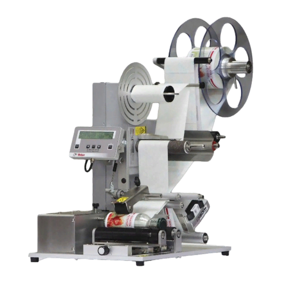
Page 24: Complete Overview
Chapter 4 Description of the labeling station 40020664 Geset 141 Complete overview Fig. 4-1: Overview of labeling station Description ALPHA COMPACT DISPLAY UNWINDER DANCER ARM UNWINDER REWINDER DANCER ARM REWINDER SWITCH- AND DRIVE GEAR BOX PEELER PLATE FOOT SWITCH Page 24 of 97... -
Page 25: Transport
Chapter 5 Transport 40020664 Geset 141 Transport Delivery The labeling station is normally delivered by a haulage contractor. Check the package for any damage. If you notice anything unusual, notify the haulage contractor immediately and note it on the delivery slip. - Page 26 Chapter 5 Transport 40020664 Geset 141 Requirements The labeling system is packed when delivered (with possible exceptions), that is: ¥ It is standing on a pallet ¥ It may be wrapped with stretch film ¥ It may be secured with additional straps and the plate feet may be screwed to the...
- Page 27 Chapter 5 Transport 40020664 Geset 141 Instruction Use the following procedure to transport the labeling system to its site of use . Step Procedure Transport the labeling system to its site of use (within 3 m). The labeling system is precisely positioned during installation by a Technician from the Bluhm Weber Group.
-
Page 28: Storage Conditions
Chapter 5 Transport 40020664 Geset 141 Storage conditions The conditions for storing a labeling station are the same as those of normal operation. For details see the chapter: "Specifications" on page 22. Instruction Store the labeling system securely as follows. -
Page 29: Installation And Initial Startup
Chapter 6 Installation and initial startup 40020664 Geset 141 Installation and initial startup Safety instructions Hazard from direct or indirect contact with voltage- conducting parts. DANGER TO LIFE! When individuals touch parts that conduct electricity arising from malfunctions can lead to death. -
Page 30: Installation
This required professional knowledge cannot be completely communicated by the operat- ing instructions; therefore a Technician from the Bluhm Weber Group needs to perform the installation or accept the labeling system in a final inspection. The warranty does not cover damage or consequential damage arising from improper installation lacking the necessary fine adjustments. -
Page 31: Setting Up The Labeling System
Chapter 6 Installation and initial startup 40020664 Geset 141 Setting up the labeling system Requirements ¥ The labeling system is unpacked and prepared (see the chapter: "Transport" on page 25) near the labeling site in the area of the installation site. -
Page 32: Overview Of The Connections
Chapter 6 Installation and initial startup 40020664 Geset 141 Overview of the connections The labeling station provides different electrical connections depending on machine confi- guration that are located laterally at the cabinet. Fig. 6-1 Electrical connections Description (X8) APPLICATOR DRIVE UNIT INSTALLED FIX (X6) ALARM LAMP (X2) PRODUCT SENSOR 1 ... -
Page 33: Connection To Supply Voltage
Chapter 6 Installation and initial startup 40020664 Geset 141 Connection to supply voltage Requirements ¥ Power supply according to "Specifications" is installed close (max. 1,5 m away) to the labeling site ¥ Power switch is OFF (in "0"-position) ¥ Power voltage cable is available Instruction The labeler is connected to supply voltage as follows . -
Page 34: Configuration Interfaces
Chapter 6 Installation and initial startup 40020664 Geset 141 Configuration interfaces (X7) Label Sensor The label sensor is used for label detection. Positioning and adjustment label sensor Information on positioning of label sensor If the detection of the label’s leading edge should be problematic during calibration , the sensor will be positioned on a possbily free (non-printed) area of the label. - Page 35 Chapter 6 Installation and initial startup 40020664 Geset 141 Information on balancing of label sensor to label If the Teach-In-button is pushed longer than 6 seconds, the bright/dark detection (NO/NC) is switched over at the sensor. For balancing of the label, push the Teach-In button only 2 seconds.
-
Page 36: Positioning And Adjustment Ultra Sonic Sensor (Usgt)
Chapter 6 Installation and initial startup 40020664 Geset 141 Positioning and adjustment Ultra Sonic Sensor (USGT) The optional ultra sonic sensor is used for transparent labels. Information on positioning of ultra sonic sensor The label web has to run about the surface of the sensor to ensure the sensor’s function. - Page 37 Chapter 6 Installation and initial startup 40020664 Geset 141 Information on balancing of label sensor to label Fig. 6-5 Balance label sensor USGT Description Specification Display Display of information The confirmation button has 2 functions: Call up of menus.
-
Page 38: (X2) Foot Switch (Product Sensor 1)
Chapter 6 Installation and initial startup 40020664 Geset 141 Arrange then a label calibration. Instruction How to teach the ultra sonic sensor by manual mode. Step Procedure Push 2x the button [].Firstly the main menu is displayed, then the automa- tic mode. -
Page 39: (X3) Low Label Sensor (Option)
Chapter 6 Installation and initial startup 40020664 Geset 141 (X3) Low Label Sensor (Option) The reflective sensor scans the label roll. A signal is fowarded, if the label roll under-runs a certain diameter. In connection with the 3-colored alarm option the signal is shown by the yellow lamp. -
Page 40: (X6) Alarm Lamp (Option)
Chapter 6 Installation and initial startup 40020664 Geset 141 Turn the headlights adjustment clockwise appr. 1 rotation until the label roll is safely detected by the sensor. Observe that no objects are detected in the background by the sensor. Loosen the adjustment screws (Pos. 1, Fig. 6-6) with the hexagon socket wrench. -
Page 41: (X9) I/O-Signal Interface (Option)
Chapter 6 Installation and initial startup 40020664 Geset 141 (X9) I/O-Signal interface (Option) The I/O interface serves for the connection of the labeling station with new machine op- tions or the customer`s controller. The PIN 4 is not used for the external trigger. It has the same function as the [Start] button of the HMI Panel. -
Page 42: Connection Examples
Chapter 6 Installation and initial startup 40020664 Geset 141 Connection examples Customer’s side PNP Alpha Compact PLC In: Ready Signal PLC In: Low label warning PLC In: Sync Signal +24VDC to customer’s side I/O Interface Internally connected with X2.1 Trigger Apply... - Page 43 Chapter 6 Installation and initial startup 40020664 Geset 141 Customer’s side PNP Alpha Compact PLC In: Ready Signal PLC In: Low label warning PLC In: Sync Signal +24VDC to customer’s side I/O Interface Internally connec- ted with X2.1 Trigger Apply...
- Page 44 Chapter 6 Installation and initial startup 40020664 Geset 141 Following graphics shows the correlation between the Start Trigger Signal and the SYNC-PULSE TIME depending on parameter setting 010 and 011 in configuration menu (see p 73). Start Tigger ( Label feed...
-
Page 45: Adjustment And Initial Operation
One or more sample products. ¥ Labels are loaded correctly. Instructions Please put the labeling system Geset 141 into operation as follows. Step Procedure Adjust labeler to label roll width (s. from page 46) Insert label roll in labeler (s. from page 47) Arrange label calibration (s. -
Page 46: Adjust Labeler To Label Roll Width
Chapter 7 Adjustment and initial operation 40020664 Geset 141 Adjust labeler to label roll width The labeler has to be adapted to the guiding of the web brake and to the dancer arm of the unwinding in the label roll’s width. For adjustment, only the guide ring (Pos. 1, Fig. 7-1) and the adjusting ring (Pos. -
Page 47: Label Loading
Chapter 7 Adjustment and initial operation 40020664 Geset 141 Label loading Requirement Power supply is off (in „0“-Position). Instruction Please insert the label web as follows. Step Procedure Open the clamp lever of the unwind disc and take it off. If there is still a label roll at the unwind mandrel remove it. -
Page 48: Arrange Label Calibration
Chapter 7 Adjustment and initial operation 40020664 Geset 141 Arrange label calibration Fig. 7-3 Calibrate labels Description LABEL PEELER BAR The labeler provides a calibration function. This function enables the labeler to detect in- dependently the label length and the application position. -
Page 49: Adjust 3-Roll System
Chapter 7 Adjustment and initial operation 40020664 Geset 141 Adjust 3-roll system The 3-roll system applies labels exactly onto cylindrical products. It possesses one fixed powered roll and two running rolls. It is the target that the product touches the drive roller completely in longitudinal direction. - Page 50 Chapter 7 Adjustment and initial operation 40020664 Geset 141 Fig. 7-5: Adjustment of 3-roll system Description KNURLED SCREW FOR HEIGHT ADJUSTMETN OF PUSHER ROLLER CLAMPING LEVER FOR AXIAL ADJUSTMENT OF PUSHER ROLLER ADJUSTMENT MANDREL TO TRANSPORT ROLLER FIXING PLATE TO LABELER Requirements ¥...
-
Page 51: Adjust Product Stop
Chapter 7 Adjustment and initial operation 40020664 Geset 141 Adjust product stop If the label material was properly inserted for the product to be labeled, the product stop can be adjusted. The product stop ensures a repeat accuracy position of the label on the product. -
Page 52: Adjust Parallelism To Product
Chapter 7 Adjustment and initial operation 40020664 Geset 141 Adjust parallelism to product The parallelism of the labeler (peeler plate) to the 3-roll system was adjusted optimally ex- factory. If the labeling should however result in a spiralization“ of the labels, i.e. label be- ginning- and end are shifted to each other (s. -
Page 53: Operation
Chapter 8 Operation 40020664 Geset 141 Operation Safety instructions Hazard from actively controlled movements. CRUSHING HAZARD! Movements of the labeling station are powered automatically by the controller in automatic operation. - Maintain a distance from moving parts. Entanglement hazard by rotating elements. -
Page 54: Start Labeling Operation
Chapter 8 Operation 40020664 Geset 141 Start labeling operation Requirements ¥ Labeling station is turned off. ¥ Labeling station is connected to power. ¥ Labeling station was adjusted correctly to the product (see chapter “Adjustment and initial operation“ from page 45). -
Page 55: Putting The System Out Of Service
Chapter 8 Operation 40020664 Geset 141 Putting the system out of service When turning off the system for several hours, the label web has to be removed from the applicator to prevent failures at restart. The label material running around the deflection rollers is curved which can cause prob- lems with the operation mode. -
Page 56: Operation Of The Display
Chapter 8 Operation 40020664 Geset 141 Operation of the Display Fig. 8-3: Display The display consists of a LC display and 5 buttons and 2 status-LEDs. It comprises a connection cable with a 5-pin M12 industry plug and it is connected at the labeler’s side (s. - Page 57 Chapter 8 Operation 40020664 Geset 141 Description Specification Entanglement hazard! Via [Jog] function an applying cy- cle is performed. Maintain a distance from moving parts. The [Enter] key has 3 functions: JOG-function: during labeling operation the Al- pha Compact can be triggered by this key.
-
Page 58: Program Menus
The PROGRAMMING MODE may only be operated by trained personnel! Wrong programmings may cause malfunctions! The display of the Geset 141 comprises three menu modes that can be reached and left by key combina- tions. Push in stand-by-condition the following buttons simultaneously to reach the following menu: Fig. -
Page 59: Indication Of Firmware Version
The current firmware version (firmware = operating system) of the controller is displayed. Current configuration set The Geset 141 provides the opportunity to store resp. call up in memory up to 9 different configuration sets. Each set can be used for an individual parameterization of the labeler (e.g. -
Page 60: Menu Diagram
Chapter 8 Operation 40020664 Geset 141 Menu diagram Page 60 of 97 Version: 30.01.15... -
Page 61: Functions Menu
Chapter 8 Operation 40020664 Geset 141 Functions menu The functions menu is reached by pressing the [] und [Enter] key simultaneously, as- suming the labeler is in emergency stop/standby condition (see above). This menu con- tains some basic settings of the labeler with following sub menus:... -
Page 62: Reset Label Counter
Chapter 8 Operation 40020664 Geset 141 RESET LABEL COUNTER The counter reading of the label counter will be reset by this function. FUNCTIONS-MENU RESET LABEL COUNTER Press either [] or [] key* to move to the next parameter ... -
Page 63: Event-Counter(Event-Counter)
Chapter 8 Operation 40020664 Geset 141 EVENT-COUNTER(EVENT-COUNTER) Using this function a number of different event counters can be called up. These provide useful statistic information about the events which are counted automatically during label- ing operation. Event Counter Information Number of all stopped applying cycles without failures... -
Page 64: Store Configuration (Config. Store)
Chapter 8 Operation 40020664 Geset 141 STORE CONFIGURATION (CONFIG. STORE) The Alpha Compact’s controller is able to store up to 9 different configurations. This fea- ture provides the opportunity to the user for a fast product change. Thus all topical set- tings (also the settings from configuration menu) are stored not only temporally. -
Page 65: Configuration-Menu
Chapter 8 Operation 40020664 Geset 141 CONFIGURATION-Menu The configuration menu can be reached by pushing the buttons [Enter] and [ ] at the same time assuming that the labeler is in stand-by. This menu includes parameter settings for the complete labeler configuration which de- termine the sequence of events during an applying cycle. -
Page 66: 000 Password
Chapter 8 Operation 40020664 Geset 141 000 PASSWORD If a configuration parameter is called up for editing by [Enter], you will have to enter a password in order to grant access only to authorized persons. The code is “123”, the access is valid for all parameters, but only as long as you do not push 2 times the [Stop]-button or switch off and on the labeler. -
Page 67: 102 Label Position (Lbl. Posit)
Chapter 8 Operation 40020664 Geset 141 102 LABEL POSITION (LBL. POSIT) Herewith the label position to the peeler bar is adjusted manually, i.e. the label stops flush with the peeler bar. The calibration function determines this value automatically (see p. - Page 68 Chapter 8 Operation 40020664 Geset 141 Adjusted and effective label speeds The label feed is subdivided in an acceleration ramp, a constant part and a delay ramp. clarifies how the effective value Fig. 8-6 ) or the originally adjusted speed (V ) is reduced.
-
Page 69: 104 Label Options (Label Options)
Chapter 8 Operation 40020664 Geset 141 104 LABEL OPTIONS (LABEL OPTIONS) These parameter can select functions that concern the label feed. If different functions should be combined, it is possible by addition of the single values. Example: doubled delay (brake ramp) and SE-function should be enabled. Please genera- te the arithmetic sum (of 004 + 064) and enter the parameter value = "068". -
Page 70: 105 Label Queue
Chapter 8 Operation 40020664 Geset 141 105 LABEL QUEUE Herewith the number of labels between peeler bar and label sensor is adjusted manually. Thus the labeler is able to compensate a missing label by feeding the gap to the next la- bel. -
Page 71: 107 Label Trigger (Label Trigger)
Chapter 8 Operation 40020664 Geset 141 107 LABEL TRIGGER (LABEL TRIGGER) Herewith it is determined which sensor input and what kind of signal generates the start signal for labeling. The functions are combined with each other with the help of arithmetic sum or are activated separately. -
Page 72: 108 Trigger Delay (Trigger Delay)
Chapter 8 Operation 40020664 Geset 141 108 TRIGGER DELAY (TRIGGER DELAY) With this parameter, the labeling procedure may be delayed. From trigger event on the la- bel will be applied onto the product according to the set distance (value x 1 mm) shifted. -
Page 73: 110 Sync Pulse Time (Sync Pulse Time)
Chapter 8 Operation 40020664 Geset 141 110 SYNC PULSE TIME (SYNC PULSE TIME) Herewith the duration of the synchronization output signal is determined. This signal serves for triggering further peripheries like rotating tamp, printer etc. The signal is acti- vated for the adjusted time at the end of an applying cycle. The time can be adjusted from 1 up to 255ms. -
Page 74: 112 Calibrate Label (Calibrate Label)
Chapter 8 Operation 40020664 Geset 141 112 CALIBRATE LABEL (CALIBRATE LABEL) This function is used to perform an automatic label calibration. An application of several labels takes place. Thereby parameters like label position and label length will be deter- mined. If a calibration is successfully finished, the values will be indicated in the second line. -
Page 75: 114 Vacuum Timeout
Chapter 8 Operation 40020664 Geset 141 114 VACUUM TIMEOUT This parameter determines the maximum time delay the Alpha Compact will try to detect label presence on tamp by sensing the vacuum in the tamp before generating an error message. This means the achievable vacuum has to be complete within the adjusted time, otherwise an error occurs. -
Page 76: 115 Extension Trigger (Extens. Trigger)
Chapter 8 Operation 40020664 Geset 141 115 EXTENSION TRIGGER (EXTENS. TRIGGER) Herewith the trigger signal for the extension of the applicator is parameterized. After the label was detected at the tamp, the date is in the labeling cycle at which the trigger is ex- pected. -
Page 77: 116 Extension Delay (Extension Delay)
Chapter 8 Operation 40020664 Geset 141 116 EXTENSION DELAY (EXTENSION DELAY) This parameter enables the programming of a delay value between trigger signal and ac- tual tamp movement. The delay starts with triggering (external or autom.). The EXTENS: DELAY will be ignored, if the parameter APPLICATOR TRIGGER has the value “000”. -
Page 78: 118 Time Out Variable Stroke (T.out Var. Stroke)
Chapter 8 Operation 40020664 Geset 141 118 TIME OUT VARIABLE STROKE (T.OUT VAR. STROKE) Any parameter value higher “000” activates the function “variable stroke” which requires an optional sensor at the tamp pad. The value you enter defines the maximum period the applicator waits during extension, in which the variable stroke sensor has to detect a product. -
Page 79: 120 Blow Delay (Blow Delay)
Chapter 8 Operation 40020664 Geset 141 CONFIGURATION BLOW-TRIGGER Press [Enter] to edit the configuration parameter. Push the *buttons [] or [] to increase or reduce the parameter value. (valid range: 000-032). Press [Enter] to save the value. -
Page 80: 122 Home Timeout
Chapter 8 Operation 40020664 Geset 141 122 HOME TIMEOUT This adjustment determines the maximum time the applicator waits for the signal of the home position sensor during retraction movement before an error message is indicated. This is also valid after switching on the labeler in case the tamp does not move to home position because e.g. -
Page 81: 124 Cycle Option
Chapter 8 Operation 40020664 Geset 141 124 CYCLE OPTION Pre-defined program processes can be selected here. The processes can be combined or activated separately with the help of arithmetic sums: Parameter Function No program sequence selected. Deactivates the timeout "variable stroke“ and generates an error if the label is lost dur- + 001 ing tamp movement (vacuum loss). -
Page 82: Parameter List Configuration
Chapter 8 Operation 40020664 Geset 141 Parameter list configuration Here all parameter of the configuration-menu can be entered. In total 9 parameter sets are available. Product / Charge Parameter LABEL LENGTH CM: LABEL POSIT CM: SPEED M/MIN LABEL OPTIONS LABELS QUEUE... -
Page 83: Programming
Chapter 8 Operation 40020664 Geset 141 PROGRAMMING Wrong parameters can lead to bugs and improper functions, also possibly leading to mechanical damage. This applies also in changes of reserved or undocumented pa- rameters as well as entering values outside the valid ranges. -
Page 84: Overview Chart
Chapter 8 Operation 40020664 Geset 141 Overview chart ALPHA.04 0000 STAND BY PROGRAMMING SEND CONFIG PROGRAMMING 016 PARAMETER VALUE 123 PROGRAMMING RECEIVE CONFIG. PROGRAMMING 017 PARAMETER VALUE 123 PROGRAMMING RESET PARAMETER PROGRAMMING 018 PROGRAMMING STORE PARAM. PROGRAMMING 255 PROGRAMMING 000... -
Page 85: Transmit Parameters (Transmit Parameters)
Chapter 8 Operation 40020664 Geset 141 TRANSMIT PARAMETERS (TRANSMIT PARAMETERS) This function allows the Alpha Compact to send its configuration parameters completely to an external PC linked to the USB port. By pushing the [Enter] button, the data will be transmitted to USB port. -
Page 86: Reset Parameter
Chapter 8 Operation 40020664 Geset 141 RESET PARAMETER This function allows to reset the operating parameters to default values that are initially pre-defined from factory, but that may also be later customized according to specific ap- plication requirements (s. "STORE PARAMETERS" on page 86). It is useful to restore a known and safe configuration in case of improper parameter modifications. -
Page 87: Maintenance And Service
Chapter 9 Maintenance and Service 40020664 Geset 141 Maintenance and Service Safety Instructions Hazard from direct or indirect contact with voltage- conducting parts. DANGER TO LIFE! When individuals touch parts that conduct electricity arising from malfunctions. - Before performing any work at the labeling station, disconnect it from electrical power. -
Page 88: Daily Maintenance/Service (After Approx. 8 Hours Of Operation)
Alcohol (*21800915) or roller solvent (*21800977) ¥ Lint-free cloth (*21800978) ¥ Label remover (*21800771) * Product recommendation! Can be ordered at the Bluhm Weber Group by 8-digit article number. Instruction Please arrange the daily maintenance/service as follows. Step Procedure Clean either daily or each time you change the label roll the drive rol- lers. -
Page 89: Weekly Maintenance/Service (After Approx. 40 Hours Of Operation)
Label remover (*21800771) Compressed air spray (*21800768) Soft brush (round or flat, appr. 100 mm) * Product recommendation! Can be ordered at the Bluhm Weber Group by 8-digit article number Instruction Please arrange the weekly maintenance/service as follows. Step Procedure Do not use aggressive detergents or scrubbing agents or hard or sharp- edged objects. -
Page 90: Cleaning Notes
Chapter 9 Maintenance and Service 40020664 Geset 141 Cleaning notes REINIGUNG NACH CLEANING AFTER EACH JEDEM ROLLENWECHSEL ! ROLL CHANGE ! BESTELL-NUMMERN / ORDER NUMBERS BESTELLANNAHME ORDER PROCESSING FRIKTIONSEINHEIT / FRICTION UNIT DRUCKKOPF / PRINTHEAD TISCHDRUCKER DESKTOP PRINTER SENSOREN/ SENSORS... -
Page 91: Spare Parts
- Only use original spare parts or parts that are specifically ap- proved by the Bluhm Weber Group. The (standard) spare parts of the labeling station are named in a separated documenta- tion that belongs to the scope of supply. -
Page 92: 10. Troubleshooting
Chapter 10 Troubleshooting 40020664 Geset 141 10. Troubleshooting Safety instructions Hazard from direct or indirect contact with voltage- conducting parts. DANGER TO LIFE! When individuals touch parts that conduct electricity arising from malfunctions. - Disconnect the labeler from power supply voltage before start- ing any work at electrical equipment. - Page 93 Chapter 10 Troubleshooting 40020664 Geset 141 Problem Possible cause Solution Wrong parameterization. Check the configuration para- meter for ramp values. Observe the influence of label length to feed speed or inquire Service- Technician by Hotline (s. page Improper label stop-position (to...
-
Page 94: Correcting Adjustments Based On Labeler Result
Chapter 10 Troubleshooting 40020664 Geset 141 Correcting adjustments based on labeler result Based on the labeler result you can draw conclusions from the necessary adjustments. Correct labeling If the labeling is performed correctly, the label is ¥ free from creases, ¥... -
Page 95: Error Messages By Display
Chapter 10 Troubleshooting 40020664 Geset 141 The label is beveled on the product. Fig. 10-3: Product with beveled label Correct the labeling result as follows: Step Procedure The inclination of the tamp plate may be adjusted incorrectly. Examine and correct the inclination of the tamp plate. -
Page 96: 11. Index
Chapter 11 Index 40020664 Geset 141 11. Index 3-roll system ............ 23 Label loading ........... 47 ACCESS CODE ........66, 84 Label Out ............10 Adjust label width ..........46 Label remover ..........88 Air Assist ............9 Label zero edge ..........51 Air Assist Tube .......... -
Page 97: 12. Ec Declaration Of Conformity
Chapter 12 EC Declaration of conformity 40020664 Geset 141 12. EC Declaration of conformity EG-KONFORMITÄTSERKLÄRUNG gemäß EG-Maschinenrichtlinie 2006/42/EG, Anhang II A EC-DECLARATION OF CONFORMITY according to EC Machinery Directive 2006/42/EC, Appendix II A DECLARATION DE CONFORMITE CE conforme à la directive machine 2006/42/CE, appendice II A...
Need help?
Do you have a question about the Geset 141 and is the answer not in the manual?
Questions and answers