Table of Contents
Advertisement
Quick Links
Original Instructions
Manual for Installation, Operation and Maintenance
ALPHA COMPACT
Part number of documentation 32708612
Copyright ©, Weber Marking Systems GmbH
Weber Marking Systems GmbH
Version: 14.12.12 /KWO
Maarweg 33
D-53619 Rheinbreitbach
E-Mail: info@webermarking.de
32708612
http://www.webermarking.de
Advertisement
Chapters
Table of Contents

Subscribe to Our Youtube Channel
Related Manuals for Weber ALPHA COMPACT


Summary of Contents for Weber ALPHA COMPACT
- Page 1 Original Instructions Manual for Installation, Operation and Maintenance ALPHA COMPACT Part number of documentation 32708612 Copyright ©, Weber Marking Systems GmbH Weber Marking Systems GmbH Version: 14.12.12 /KWO Maarweg 33 D-53619 Rheinbreitbach E-Mail: info@webermarking.de 32708612 http://www.webermarking.de...
- Page 2 Blank page...
-
Page 3: Table Of Contents
Tamp-Blow-Mode ......................... 27 Tamp-On-Mode ..........................27 Blow-On-Mode ..........................27 Complete Overview of the Alpha Compact ................ 28 Subdivision of the product range of the Alpha Compact ............ 28 Transport ......................29 Delivery ..........................29 Scope of Delivery ......................... 29 Transport and Unpackaging .................... - Page 4 Placing the Labeler ........................34 Positioning the Labeler ......................... 35 *² System for fixing at stands of the Bluhm Weber Group! ............36 Connecting the Labeler ...................... 37 Safety Instructions ........................37 Connection to Supply Voltage ...................... 37 ...
- Page 5 PASSWORD: 00000 ........................112 List of parameter PROGRAMMING ................. 112 Safety instructions ........................112 Firmware History ......................113 Hardware History ......................113 System Options ....................114 Subdivision of Alpha Compact Product Range ..............114 14.12.2012 page 5 of 135 Version:...
- Page 6 Contents Alpha Compact 32708612 Pre-configured Alpha Compact (Basis version) ................. 114 Retrofit Options (Field Installable) ....................114 Factory Installable Options (Factory Installable) ................ 114 Modular construction ........................115 Maintenance ...................... 116 Safety Instructions ........................116 ...
-
Page 7: General Information
Chapter 1 General Information Alpha Compact 32708612 General Information General Survey Congratulations! You have purchased a high-quality labeling system. Our concern is to make sure that you profit from this system to your entire satisfaction over many years. In order to en- sure this, we strongly recommend you to let our experienced specialists perform the installation (hints s. -
Page 8: Purpose And Scope Of This Operation Instruction
Chapter 1 General Information Alpha Compact 32708612 Purpose and Scope of this operation instruction These operating instructions will help you get to know the system and use it properly. They contain important instructions for the user on how to use the system safely and cor- rectly. -
Page 9: Service Hotline
Chapter 1 General Information Alpha Compact 32708612 Service Hotline The technical Service-Hotline is available from Mondays to Fridays 24 hours. In urgent cases spare parts can be dispatched until approx. 22:00 p.m. Tel : +49 (0)2224 - 7708 - 440... -
Page 10: Explanation Of Technical Terms
Chapter 1 General Information Alpha Compact 32708612 Explanation of Technical Terms Technical Term Explanation Adhesive Strings Leaked adhesive at the label edge may adhere the label at the label liner. The printed label adheres to the liner and can thus not be fed to the Tamp. - Page 11 Home Position The user interface (HMI) is the place where the user comes into contact with the system. The Alpha Compact can be equipped for selection either with HMI panel or HMI display. Mode in which a numeral value in the display can be adjusted Input-Mode higher or lower.
- Page 12 Chapter 1 General Information Alpha Compact 32708612 Shows the label format width x length (in feed direction of the Label Size label) in mm (millimeter). Leading Edge The front edge of the product/label that triggers the label applica- tion (see also Edge Detection).
- Page 13 Chapter 1 General Information Alpha Compact 32708612 Technical Term Explanation Roll holder (normally for 3 inch cardboard cores) for rewinding Rewinder the label web. The rewinder winds up the web coming from the print engine. It is triggered by a dancer arm (see dancer arm).
-
Page 14: Safety Regulations
Chapter 2 Safety Regulations Alpha Compact 32708612 Safety Regulations Behavior in Case of an Emergency The operating personnel have to be familiar with the operation and the location of safety, accident notification-, first aid- and rescue devices. What to do in Case of an Emergency? ... -
Page 15: Intended Use
Chapter 2 Safety Regulations Alpha Compact 32708612 Intended Use The working reliability of the labeler is ensured only with intended use. An Intended Use applies if … the labeler is used exclusively for automatic labeling of moved respectively stopped products. -
Page 16: Reasonably Forseeable Misuse
Chapter 2 Safety Regulations Alpha Compact 32708612 Reasonably Forseeable Misuse Another use as fixed in the „Intended Use“ or even more applies as not intended! For damages caused by not inteded use: the operator bears the complete responsibility, ... -
Page 17: Sources Of Danger At Labeler
Chapter 2 Safety Regulations Alpha Compact 32708612 Sources of Danger at Labeler Fig.: 2-1: Sources of Danger at Labeler The rollers of the unit that brings the objects forward rotate in the opposite direction so that objects may be detected and may be pulled between the rollers. A protective plate here protects the user from injuries. - Page 18 Chapter 2 Safety Regulations Alpha Compact 32708612 *²Labeler with optional applicator Fig.: 2-2: Sources of danger at the applicator Tamp Blow, rotating tamp and pneumatic peeler blade All applicators of labelers have been designed according to safety criteria. The arising forces at the Tamp are limited to 50 Newton for both movements of the stroke, which may be potential risks of injury to persons classified as low (usually reversible).
-
Page 19: Safety Instructions
Chapter 2 Safety Regulations Alpha Compact 32708612 Safety Instructions Danger caused by direct or indirect contact with live parts. DANGER TO LIFE! Contact of persons with live parts. ̶ Before performing any work on electrical equipment of the la- beler, separate from power source. -
Page 20: Remaining Risks
Chapter 2 Safety Regulations Alpha Compact 32708612 Health hazard caused by rough surfaces HEALTH HAZARD! The friction rollers have a rough surface. Long contact may cause abrasions. ̶ Do not grip in, at or between moving parts. Health Hazard due to inappropriate handling of lubricants and... -
Page 21: Warnings On The Labeler
Chapter 2 Safety Regulations Alpha Compact 32708612 Warnings on the labeler Special hazards arising from the labeler are identified with yellow stickers. The pictograms indicate hazards: Danger Life-threatening hazard by electrical power Crushing hazard Entanglement hazard Danger due to hot surface... -
Page 22: Protection Device
Chapter 2 Safety Regulations Alpha Compact 32708612 Protection device Machine cladding The fixed and screwed machine cladding (cover) protects the user from mechanical and electrical hazards. Authorized Personnel Work at the labeler should only be performed by reliable personnel. Please comply with the legal age! Only trained personnel are allowed to operate the labeler. -
Page 23: Personal Protective Equipment
Chapter 2 Safety Regulations Alpha Compact 32708612 Personal Protective Equipment Wear following protective equipment when performing work at the labeler: SAFETY SHOES Wear for protection against falling off parts and slipping. PROTECTIVE CLOTHING Are tight-fitting clothes with low tensile strength, with tight sleeve and without distant parts. -
Page 24: Technical Specifications
Chapter 3 Technical Specifications Alpha Compact 32708612 Technical Specifications Dimensions Labeler 715 x 310 x 590 (dependent on applicator version) (H x W x D in mm) Weight approx. 22 kg (without label roll) 100-240V / 47-63Hz (1~) with protective conductor... -
Page 25: Performance Data
Chapter 3 Technical Specifications Alpha Compact 32708612 Performance Data Application Accuracy (Wipe-On and Tamp-On- +/- 0,8 mm Applicators) Application Rate Wipe-On / Up to 600 labels per min. Blow Box Application Rate Tamp-On Up to120 labels per min. Applicators Application Performance Max. -
Page 26: Description Of The Labeler
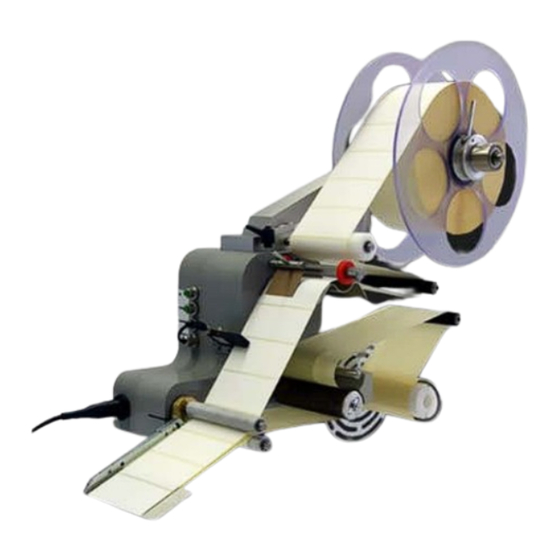
Description of the Labeler Application Field of the Labeler The ALPHA Compact is used for the automatically labeling of products. Depending on machine attitude the labeling can be arranged on the sides or on the top face or the bot- tom side onto the product without any interruption. -
Page 27: Application Modi
Alpha Compact. Wipe-On The label is peeled off from peeler blade and applied onto the passing product. This mode is the standard application mode of the Alpha Compact and it is possible without further mounting parts (applicators). Tamp-Blow-Mode The label is positioned by an optional applicator to a vacuum tamp and at triggering it is extended to the product and it is then blown off onto the product. -
Page 28: Complete Overview Of The Alpha Compact
DANCER ARM FOR REWINDING REWINDER FEEDING UNIT (FRICTION ROLLERS) CLAMPING FLANGE PEELER BAR (PEELER BLADE) LABEL SENSOR CONNECTORS BELT BRAKE Subdivision of the product range of the Alpha Compact See chapter [System Options] p.114. 14.12.2012 page 28 of 135 Version:... -
Page 29: Transport
Scope of Delivery The scope of delivery of the Alpha Compact depends on the ordered options and the cus- tomer’s application. Please control the scope of delivery when receiving the systems on the basis of the delivery note. - Page 30 Chapter 6 Installation and Initial Operation Alpha Compact 32708612 To avoid damaging the labeling during transport, do not overturn the labeler, avoid strong vibrations, protect it from humidity and rain. If it is supplied in cardboard boxes, please store at maximum three systems on top of each other.
- Page 31 Chapter 6 Installation and Initial Operation Alpha Compact 32708612 Fig. 5-1: Packaging Examples Pos. Description PACKAGING EXAMPLE WITH CARDBOARD BOX OR BOX PACKAGING EXAMPLE WITH PROTECTIVE CABINET STRETCH FOIL PALLET TRANSPORT SECURING SCREW RUBBER FEET STRAPS Instruction Please transport the labeler to the installation site as follows:...
- Page 32 Chapter 6 Installation and Initial Operation Alpha Compact 32708612 Fig. 5-2: Alpha Compact with Protective Cabinet from Pallet. Lift the labeler with a double hand fork lift truck resp. fork lift truck in shown way from the pallet (s.Fig. 5-2: ).
-
Page 33: Storage Conditions
Chapter 6 Installation and Initial Operation Alpha Compact 32708612 Storage Conditions The environmental conditions for storage of the labeler relate to them of the normal opera- tion. Details see chapter "Technical Data". Instruction Please store the labeler safety as follows:... -
Page 34: Installation And Initial Operation
Therefore the installation of the labeler must be made by a technician from the Bluhm Weber Group or examined by a final inspection. Damage or damages based on an incor- rect installation, represent no case of warranty. -
Page 35: Positioning The Labeler
MOUNTING POINT RIGHT SIDE MOUNTING POINT BOTTOM SIDE The Alpha Compact is equipped with four possible fixing positions at the cabinet. Depend- ing on the order there are four M8 or four M6 threads at one of the positions. The other 3 mounting points are marked. -
Page 36: ² System For Fixing At Stands Of The Bluhm Weber Group
Chapter 6 Installation and Initial Operation Alpha Compact 32708612 *² System for fixing at stands of the Bluhm Weber Group! If the system is fixed at a Stand of the Bluhm Weber Group, you will please follow the in- stallation instructions. Requirements ... -
Page 37: Connecting The Labeler
̶ Keep away from moving parts. Danger of property damage The Alpha Compact can be connected to 100V up to 240V / 47-63 Hz. A false adjustment of the input-voltage leads to a damage of the system and is no case of warranty! -
Page 38: Configuration Interfaces
Alpha Compact 32708612 Configuration Interfaces Dependent on machine configuration the ALPHA Compact has different connections. The connections are located laterally at the cabinet of ALPHA Compact. Belated extension of the interfaces is only allowed to be carried out by qualified personnel and is described in the service manual. -
Page 39: Configuration Product Sensor Wenglor Ld86Ptc (Option)
Chapter 6 Installation and Initial Operation Alpha Compact 32708612 Wenglor LD86PTC (Option) Configuration Product Sensor The functioning of the standard sensor Wenglor LD86PCT3 is adjusted directly at the sensor via teach-button. Fig.: 6-3 Wenglor LD86PTCT3 Description SENSOR-CONNECTION LINE TEACH-BUTTON LED RED DIRT STATUS DISPLAY... -
Page 40: Product Sensor Positioning
Chapter 6 Installation and Initial Operation Alpha Compact 32708612 Labeler is connected with supply voltage. Control of product supply and if necessary the customer`s conveying system. Instruction Please adjust the sensor LD86PCT3 to the adequate teach modes. Step... - Page 41 Chapter 6 Installation and Initial Operation Alpha Compact 32708612 Requirements Product supply is stopped. Labeler is switched-on. Labels are loaded. Instruction Please position the product sensor as follows. Step Procedure Please place a product below tamp in the way that a label would be applied on the desired position.
-
Page 42: Sensitivity Adjustment
Chapter 6 Installation and Initial Operation Alpha Compact 32708612 Sensitivity Adjustment The following description deals with a light barrier with reflector [type: Wenglor LD86NCT3] and a reflective light sensor [type: Wenglor HD12PTC ] (s. Fig.: 6-5 ). Please fix reflective light sensor or rather light barrier and reflector before you perform the follow- ing adjustments. - Page 43 Chapter 6 Installation and Initial Operation Alpha Compact 32708612 Instruction Please adjust the sensitivity of the light barrier or rather the reflective light sensor as fol- lows. Step Procedure Please place a product below tamp in the way that a label would be applied on the desired position.
-
Page 44: Test Run
Chapter 6 Installation and Initial Operation Alpha Compact 32708612 Test Run After you are finished with all adjustments, please check the repeated application accura- Requirements Control of product supply. Labeler is switched-on. Position of product sensor is adjusted. -
Page 45: Low Label Sensor (Option)
Chapter 6 Installation and Initial Operation Alpha Compact 32708612 Low Label Sensor (Option) The low label prewarning is used to display a pending end of the label roll. If a pending roll end was displayed, the user should insert a new label roll to keep the labeler ready for operation. - Page 46 Chapter 6 Installation and Initial Operation Alpha Compact 32708612 Requirements Product transport is stopped. Labeler is ready for operation. Required equipment: 4mm Hexagon socket wrench Philips screw driver Große 00 Instructions Please adjust the Low Label Sensor as follows.
-
Page 47: (X5) Encoder (Option)
For an optimum labeling result the label applying speed has to coincide with the product transportation speed. If the products are always fed with the same speed to the labeler Alpha Compact, a fixed adjustment of the applying speed is sufficient. If the product transportation speed varies, the label applying speed has to be synchronized by means of an optional encoder. - Page 48 Chapter 6 Installation and Initial Operation Alpha Compact 32708612 To be able to dimension the encoder and the transmission correctly, please find below the procedure for our standard encoder with 2000 pulses per rotation (article number 33003611). For the initial operation of the encoder, an HMI display or an *“USB- connection is required.
-
Page 49: (X6) Alarm Lamp (Option)
Chapter 6 Installation and Initial Operation Alpha Compact 32708612 (X6) Alarm Lamp (Option) The connection of an optional alarm lamp happens via M12, 8 pin plug. Fig.: 6-8: Pin Assignment Alarm Lamp Assignment + 24V DC RED LAMP + 24V DC YELLOW LAMP... -
Page 50: (X7) Label Sensor
Chapter 6 Installation and Initial Operation Alpha Compact 32708612 (X7) Label Sensor The connection of the label gap sensor happens via a short cable that is lead out laterally of the cabinet and that has a M8, 5 pin plug socket. This socket is suitable for the stand- ard provided label gap sensor. -
Page 51: Adjusting Label Sensor To Label
Chapter 6 Installation and Initial Operation Alpha Compact 32708612 Requirements Labels are loaded. Product supply is stopped. Labeler is separated from supply voltage and air pressure. Adjusting Label Sensor to Label Instruction Please adjust the label sensor position as follows. -
Page 52: Option Micro-Switch Scanning As Product Sensor
Chapter 6 Installation and Initial Operation Alpha Compact 32708612 Labeler is switch on. Instruction Please adjust the label sensor to the product as follows. Step Procedure Push the teach button not too long. You will misalign the basic settings of positive / negative edge. -
Page 53: (X8) Applicator (Option)
Chapter 6 Installation and Initial Operation Alpha Compact 32708612 Instruction micro-switch scanning Please adjust the as follows. Step Procedure Lead a label gab at the label scanning position. Turn the knurl wheel until the indicator light of the senosor goes straigt out. -
Page 54: (X9) I/O (Option)
Alpha Compact 32708612 (X9) I/O (Option) The I/O interface serves for the connection of the Alpha Compact with new machine op- tions or the customer`s controller. The PIN 4 is not used for the external trigger. It has the same function as the [Start] button of the Control Panel. A signal will be activated and maybe failure messages will be reset by pushing. - Page 55 Chapter 6 Installation and Initial Operation Alpha Compact 32708612 Following graphics shows the correlation between the Start Trigger Signal and the SYNC- PULSE TIME depending on parameter setting 010 and 011 in configuration menu (see p. 97). Start Tigger (...
-
Page 56: Connection Example
Chapter 6 Installation and Initial Operation Alpha Compact 32708612 Connection example Fig.: 6-16: Connection example 14.12.2012 page 56 of 135 Version:... -
Page 57: (X10) Hmi
A simple user panel or a display panel with a M12, 5 pin plug may be connected at the Al- pha Compact. Both controllers are connected with the Alpha Compact with the same con- nection. When using an optional USB-connection, the settings can also be configured by a PC. -
Page 58: Usb Connection (Option)
USB connection (Option) Fig.: 6-18: USB connection The Alpha Compact can optionally be equipped with an USB 2.0. The Alpha Compact will be programmed and operated with software and PC. Additionally extensive diagnosis and error detections can be evaluated. A controller is not necessary in this case. - Page 59 Chapter 6 Installation and Initial Operation Alpha Compact 32708612 Requirements Labeler is without power and compressed air Label rolls Required equipment 2mm Hexagon socket wrench Please adjust the labeler to the label liner’s width as follows. Step...
-
Page 60: Loading And Changing Label Material
Chapter 6 Installation and Initial Operation Alpha Compact 32708612 Loading and Changing Label Material Safety Instructions Danger of drawing in by rotating elements. DANGER OF DRAWING IN Rotating elements at labeler, rewinder, web brake and rollers of the friction unit. - Page 61 Chapter 6 Installation and Initial Operation Alpha Compact 32708612 Requirement The labeler has to be switched off when loading label web. Instruction Please load label web as follows. Step Procedure If label web is still loaded, cut it in region of the peeler blade.
-
Page 62: Dancer Arm Unwinder- Setting
Chapter 6 Installation and Initial Operation Alpha Compact 32708612 Dancer arm unwinder- setting Safety instructions Danger of drawing in by rotating elements. DANGER OF DRAWING IN Rotating elements at labeler, rewinder, web brake and rollers of the friction unit. ̶ Disconnect the labeler from supply voltage when performing any work. - Page 63 Chapter 6 Installation and Initial Operation Alpha Compact 32708612 The unwinding is used to support the label roll. The label material is peeled off by a draw- ing unit from the unwinder. To provide a constant label web tension, the unwinder axis slows down or loosens if applicable by two brake belts that are triggered by a dancer arm.
-
Page 64: Label Calibration
LABEL PEELER BAR The Alpha Compact provides a function to calibrate labels. This function enables the labe- ler to detect the label length and the position to the peeler bar. After the calibration, the la- bel is located flush with the peeler bar. For most applications, this is the correct label posi- tion. -
Page 65: Settings At Wipe-On System
Chapter 6 Installation and Initial Operation Alpha Compact 32708612 Instruction Please calibrate the labels via display controller as follows. Schritt Vorgehen Danger of drawing in by rotating elements. If you are not in the starting mode please push the [Start] button. - Page 66 Chapter 6 Installation and Initial Operation Alpha Compact 32708612 Fig.: 6-24 Wipe-On-Setting Description PEELER BLADE CLAMPING SCREW PUSHER ROLLER PRODUCT DISTANCE TO PEELER BAR DISTANCE BETWEEN PUSHER ROLLER AND PRODUCT A the distance between peeler bar and pusher roller. B the adjustment of the pusher roller to the product.
-
Page 67: Adjust Peeler Blade To The Deflection Rollers
Chapter 6 Installation and Initial Operation Alpha Compact 32708612 Instruction Please adjust the Wipe-On system as follows. Step Procedure Please put a product directly below the peeler bar. The conveying system has to be switched-off. Loosen the screw of the roller holder and adjust the roller approx.to product height. - Page 68 Chapter 6 Installation and Initial Operation Alpha Compact 32708612 Fig.: 6-26: Adjust extender bearing Description EXTENDER BEARING CLAMPING SCREWS Requirements Product feed is stopped. Disconnect labeler from voltage supply. Required equipment: 5mm Hexagon socket wrench Instruction Please adjust the distance of the peeler blade’s mounting to the deflection roller as fol- lows.
-
Page 69: Settings Coupling Rewinder
Chapter 6 Installation and Initial Operation Alpha Compact 32708612 Settings coupling rewinder Fig.: 6-27: Adjustment coupling Description DIRECTION OF ADJUSTMENT DANCER ARM CORE ADJUSTMENT SCREW CYLINDER BOLT SETSCREW (FIXING) AXIS TO COUPLING Danger of damage. The rewinder has a free-wheeling that impedes the unwinding of the liner material. - Page 70 Chapter 6 Installation and Initial Operation Alpha Compact 32708612 Please adjust the coupling as follows. Step Procedure Loosen the setscrew (Fig.: 6-27, Pos.6). Loosen the adjusting screw (Fig.: 6-27, Pos.4). Push the dancer arm (Fig.: 6-27, Pos.2) in direction of the adjustment (to the cover) and keep it pushed.
-
Page 71: ²Air Assist Setup-With Optional Applicator
Chapter 6 Installation and Initial Operation Alpha Compact 32708612 *²Air assist setup-with optional applicator Danger due to actively controlled movements. DANGER OF BEING CRUSHED! The movements of the applicator are driven by pneumatic cylin- ders. Maintain a distance from applicator. - Page 72 Chapter 6 Installation and Initial Operation Alpha Compact 32708612 Requirements Labeler is turned on No transportation of products Required equipment: Screw driver G00 Screw wrenchs 14 and 12 Instructions Please adjust the air assist as follows Step Procedure Check firstly if the air assist beams hits appr. 10 mm behind the leading edge of the tamp (see Fig.: 6-29).
-
Page 73: ²Adjust Angle Of Rotation At Optional Rotating Tamp
DANGER OF BEING CRUSHED! The movements of the applicator are driven by pneumatic cylin- ders. Maintain a distance from applicator. Fig. 6-3: Alpha Compact with rotating tamp Description SWING MODULE ROTATING TAMP The rotating angle of the rotating tamp has to be adjusted appropriate to the product. - Page 74 Chapter 6 Installation and Initial Operation Alpha Compact 32708612 Fig. 6-4: Alpha Compact with rotating tamp Description COUNTER NUT *² OPTIONAL SHOCK ABSORBER CLAMPING SCREW TO END STOP CLAMPING SCREW TO END STOP *² OPTIONAL SHOCK ABSORBER COUNTER NUT 1. END STOP AT LH / 2. END STOP AT RH 2.
- Page 75 Chapter 6 Installation and Initial Operation Alpha Compact 32708612 Instructions Please adjust the rotating angle at the swing arm as follows. Step Procedure Pull off the protective cap at the swing module. Loosen the clamping screw to the 1. end position by means of a hexagon socket wrench.
-
Page 76: Operation
Turn on and off labeler (without power supply) The labeler Alpha Compact is turned on and off by plugging in and out the power supply of the controller. Turn on and off labeler with optional power supply Fig. -
Page 77: Start Labeling Operation
Chapter 8 System Options Alpha Compact 32708612 The labeler Alpha Compact is turned on and off by the *² power supply. *² Only if labeler has the appropriate feature Start Labeling Operation Requirements The initial operation (s. chapter "Installation and Initial Operation") was finalized successfully. -
Page 78: Stop Labeling Operation
Chapter 8 System Options Alpha Compact 32708612 Stop Labeling Operation Safety Instructions When the system is stopped about several hours you have to take the label material off the labeler. The label material gets bent in the area of the deflection rollers that might lead to failures during operation mode. -
Page 79: Operation Of The Hmi Panel
Chapter 8 System Options Alpha Compact 32708612 Operation of the HMI Panel Fig. 7-2: HMI-Panel The HMI Panel consists of 4 buttons, 2 control dials and 2 control-LEDs. It comprises a connection cable with a 5-pin M12 industry plug and it is connected at the labeler’s side. - Page 80 Chapter 8 System Options Alpha Compact 32708612 Description Specification LED Stop If the red LED above the [Stop]-button lights, the "labeler’s standby status" is interrupted. The [Start]-button is used to start the labeler. The labeling operation is activated by pushing and resp. error messages are acknowledged.
-
Page 81: Operation Of The Hmi Display
Chapter 8 System Options Alpha Compact 32708612 Operation of the HMI Display Fig. 7-3:: Display-Controller The HMI Display consists of a LCD-Display and 5 buttons as well as 2 control-LEDs. It comprises a connection cable with a 5-pin M12 industry plug and is connected at the la- beler’s back side. - Page 82 Chapter 8 System Options Alpha Compact 32708612 Term Description The [Enter] key has 3 functions: JOG-function: during labeling operation the alpha Compact can be triggered by this key. In combination with further keys for calling up menus. ...
-
Page 83: Program-Menus
A false programming may cause failures! The display controller of the Alpha Compact includes three menu modes which can be reached and left via key combination. Push the following buttons together at the same time in stand-by status to get to the desired menu: Fig. -
Page 84: Failure Reset
(firmware-history on page 113). Current Configuration Dataset The Alpha Compact offers the opportunity to store up to 4 different sets of parameters. Each dataset can be used for an individual parameterization of the labeler (e.g. for differ- ent production conditions). -
Page 85: Menu-Diagram
Chapter 8 System Options Alpha Compact 32708612 Menu-Diagram 14.12.2012 page 85 of 135 Version:... -
Page 86: Function-Menu
Chapter 8 System Options Alpha Compact 32708612 FUNCTION-MENU You can reach the function menu by pushing [] and [Enter] at the same time assuming that the labeler is in stand-by (s.a.). This menu includes some basic settings of the labeler... -
Page 87: Reset Label Counter
Chapter 8 System Options Alpha Compact 32708612 RESET LABEL COUNTER The counter reading of the label counter will be reset by this function. FUNCTION-MENU RESET LABEL COUNTER Push the * buttons [] or [] to reach the next parameter. -
Page 88: Event Counter
Chapter 8 System Options Alpha Compact 32708612 EVENT COUNTER Using this function a number of different event counters can be called up. These provide useful statistic information about the events which are counted automatically during label- ing operation. Event Counter Information... -
Page 89: Save Configuration
Alpha Compact 32708612 SAVE CONFIGURATION The Alpha Compact’s controller is able to store up to 9 different configurations. This fea- ture provides the opportunity to the user for a fast product change. Thus all topical set- tings (also the settings from configuration menu) are stored e. g. speed, Encoder turned... -
Page 90: Configuration-Menu
Chapter 8 System Options Alpha Compact 32708612 CONFIGURATION-Menu The configuration menu can be reached by pushing the buttons [Enter] and [ ] at the same time assuming that the labeler is in stand-by. This menu includes parameter settings for the whole labeler configuration which deter- mine the sequence of events during an applying cycle. -
Page 91: Password: 000
Chapter 8 System Options Alpha Compact 32708612 PASSWORD: If a configuration parameter is called up for editing by [Enter], you will have to enter a password in order to grant access only to authorized persons. The code is “123”, the access is valid for all parameters, but only as long as you do not push 2 times the [Stop]-button or switch off and on the labeler. -
Page 92: Label Position (Label Pos.)
Chapter 8 System Options Alpha Compact 32708612 002 LABEL POSITION (LABEL POS.) Herewith the label position to the peeler bar is adjusted manually. There is the possibility of automatic label calibration. CONFIGURATION LABEL POSITION cm: 11,8 Push [Enter] to edit the configuration parameter (in case of password query see page 91). -
Page 93: Label Options
Chapter 8 System Options Alpha Compact 32708612 Detailed information on application rate Fig. 7-6 Label Feed Description START RAMP LABEL FEED SPEED STOP RAMP AVERAGE SPEED Acceleration (start ramp) and delay (stop ramp) of label feed speed are generally linear. -
Page 94: Label Options
Chapter 8 System Options Alpha Compact 32708612 004 LABEL OPTIONS Herewith the acceleration ramp for label application is adjusted. You can also select fur- ther functions. The functions are combined with each other with the help of arithmetic sum or are activated separately. -
Page 95: Labels Burst (Labels Burst)
Chapter 8 System Options Alpha Compact 32708612 006 LABELS BURST (LABELS BURST) Herewith the number of label application per start signal (trigger signal) is adjusted. If the parameter is set on 000, 1 label per start signal will be applied. -
Page 96: Trigger Delay (Trigger Delay)
Chapter 8 System Options Alpha Compact 32708612 008 TRIGGER DELAY (TRIGGER DELAY) Herewith a delay is adjusted between trigger and label application. The delay can be be- tween 0 up to app. 255 mm. The length of the pulse corresponding to each entered value x 1 mm. -
Page 97: Sync Pulse Time (Sync Pulse Time)
Chapter 8 System Options Alpha Compact 32708612 010 SYNC PULSE TIME (SYNC PULSE TIME) Herewith the duration of the synchronization output signal is determined. This signal serves for triggering further peripheries like rotating tamp, printer etc. The signal is acti- vated for the adjusted time at the end of an applying cycle. -
Page 98: Calibrate Label (Calibrate Label)
Chapter 8 System Options Alpha Compact 32708612 012 CALIBRATE LABEL (CALIBRATE LABEL) This function is used to perform an automatic label calibration. An application of several labels happens. Thereby parameters like label position and label length will be deter- mined. If a calibration is successfully finished, the values will be indicated in the second line. -
Page 99: Vacuum Timeout: 200
Alpha Compact 32708612 014 VACUUM TIMEOUT: 200 This parameter determines the maximum time delay the Alpha Compact will try to detect label presence on tamp by sensing the vacuum in the tamp before generating an error message. This means the achievable vacuum has to be complete within the adjusted time, otherwise an error occurs. -
Page 100: Applic-Trigger : 000
Chapter 8 System Options Alpha Compact 32708612 015 APPLIC-TRIGGER : 000 Herewith the trigger signal for the extension of the applicator is parameterized. Af- ter the label was detected at the stamps, the date is in the labeling cycle at which the trigger is expected. -
Page 101: Extension Delay
Chapter 8 System Options Alpha Compact 32708612 016 EXTENSION DELAY This parameter enables the programming of a delay between trigger signal and actual tamp movement. The delay starts with triggering (external or autom.). The EXTENS: DE- LAY will be ignored, if the parameter APPLICATOR TRIGGER has the value “000” (cp. -
Page 102: Time Out Variable Stroke
Chapter 8 System Options Alpha Compact 32708612 Push [Enter] to edit the configuration parameter (in case of password query see page 91). Push the *buttons [] or [] to increase or reduce the parameter value. (unit = value x 10ms, value "000" = Blow-On mode). -
Page 103: Blow Trigger
Depending on the configuration additionally the trigger can be used for the control of the external stop function or rather for starting the labeling operation. If the Alpha Compact operates with a variable stroke, the value has to be “000” according to factory setting. -
Page 104: Blow Delay: 000
Chapter 8 System Options Alpha Compact 32708612 020 BLOW DELAY: This configuration parameter delays the blow-off by the adjusted value. The adjustment will be ignored when the previous parameter „BLOW TRIGGER“ is set on “000“. CONFIGURATION BLOW DELAY. Push [Enter] to edit the configuration parameter (in case of password query see page 91). -
Page 105: Home Timeout
Chapter 8 System Options Alpha Compact 32708612 022 HOME TIMEOUT This adjustment determines the maximum time the applicator waits for the signal of the home position sensor during retract movement before an error message is indicated. This is also valid after switching on the labeler in case the tamp does not move to home posi- tion because e.g. -
Page 106: Cycle Option: 000
Chapter 8 System Options Alpha Compact 32708612 024 CYCLE OPTION: Pre-defined program processes can be selected here. The processes can be combined or activated separately with the help of arithmetic sums: deactivates the timeout "variable stroke“ and generates an error if the label is lost during tamp movement (vacuum loss);... -
Page 107: Programming
Chapter 8 System Options Alpha Compact 32708612 PROGRAMMING Wrong parameters can lead to bugs and improper functions, also possibly leading to mechanical damage. This applies also in changes of reserved or undocumented pa- rameters as well as entering values outside the valid ranges. -
Page 108: Overview Chart Programming
Chapter 8 System Options Alpha Compact 32708612 Overview chart PROGRAMMING ALPHA.04 0000 STAND BY PROGRAMMING TRANSMIT CONFIG PROGRAMMING 016 PARAMETER VALUE PROGRAMMING RECEIVE CONFIG: PROGRAMMING 017 PARAMETER VALUE PROGRAMMING RESET PARAMETER PROGRAMMING 018 PROGRAMMING STORE PARAM. PROGRAMMING 255 PROGRAMMING 000... -
Page 109: Call Up, Navigate And Edit Programming
To exit PROGRAMMING, push [Stop]. Provided that you are in PROGRAMMING mode, you will receive access to a sub menu with 4 more functions concerning the complete configuration of the Alpha Compact by pushing the buttons [] and []. PROGRAMMING TRANSMIT CONFIG. -
Page 110: Transmit Parameters
To clone the configuration of a master unit, the output may be stored as a text file and re- transmitted to other Alpha Compact machines. The text files can be edited on a PC and retransmitted to the labeler and thus an external service programming is possible. -
Page 111: Reset Parameter
To help recovering operation on a machine locked due to improper configuration, it is also possible to activate this function at switch-on the Alpha Compact by pressing simultane- ously the [Start] + [Stop] keys for at least 5 seconds. -
Page 112: Password: 00000
Chapter 8 System Options Alpha Compact 32708612 PASSWORD: 00000 If in programming a parameter is called up with [Enter] in order to change it, the machine asks for a PASSWORD to proceed, in order to limit access only to authorized personnel. -
Page 113: Firmware History
Chapter 8 System Options Alpha Compact 32708612 Firmware History The firmware is the ‘’operating system’’ of the Alpha Compact labeler’s control unit. Following is the chronological order of all firmware releases (including changes) until the publication of this Manual. Version Alpha 01 Creation date: 27. -
Page 114: System Options
Chapter 9 Maintenance Alpha Compact 32708612 System Options The labeler Alpha Compact can be equipped with many different options. The systems op- tions are subdivided into three groups. Additionally we offer many customized special solutions like protective cabinets, stands, special labeling stations and more. These options require a check and examination. -
Page 115: Modular Construction
Chapter 9 Maintenance Alpha Compact 32708612 Modular construction The Alpha Compact is assembled based on modules according to special requirements of the customers in modular construction. There are assembled in our factory according to the required configuration. The most important modules are: ... -
Page 116: Maintenance
Chapter 9 Maintenance Alpha Compact 32708612 Maintenance Safety Instructions Danger caused by direct or indirect contact to live parts DANGER TO LIFE! Contact of persons with live parts which are energized by failures. ̶ Disconnect the power from the machine before you perform any work at the labeler. - Page 117 Chapter 9 Maintenance Alpha Compact 32708612 Danger caused by icing. HEALTH HAZARD Compressed air spray (21800768) is filled with liquid CO ̶ Do not hold bin precipitate. Liquid CO can escape of bin and icing occurs. Damage to sensoric optic.
- Page 118 Chapter 9 Maintenance Alpha Compact 32708612 REINIGUNGSHINWEISE / CLEANING NOTES REINIGUNG NACH CLEANING AFTER EACH ROLL CHANGE ! JEDEM ROLLENWECHSEL ! BESTELL-NUMMERN / ORDER NUMBERS BESTELLANNAHME ORDER PROCESSING FRIKTIONSEINHEIT / FRICTION UNIT DRUCKKOPF / PRINTHEAD TISCHDRUCKER GUMMIWALZEN / PLATEN ROLLERS...
-
Page 119: Daily Maintenance (After Approx. 8 Hours Of Operation)
Lint-free cloth (*21800978) Label remover (*21800771) Soft brush (round or plain approx.. 10 mm) * Product recommendation! Can be ordered at the Bluhm Weber Group by 8-digit article number. Instruction Please arrange the daily maintenance as follows: Step Procedure Clean labeler according to the cleaning instructions. -
Page 120: Weekly Maintenance (After Approx. 40 Hours Of Operation)
Label remover (*21800771) Compressed air spray (*21800768) Soft brush (round or plain approx. 10 mm) * Product recommendation! Can be ordered at the Bluhm Weber Group by 8-digit article number. Instruction Please arrange the weekly maintenance as follows. Step Procedure Clean labeler according to the cleaning instructions. -
Page 121: Six Month Maintenance (After Approx. 1000 Hours Of Operation)
Chapter 9 Maintenance Alpha Compact 32708612 Six month Maintenance (After Approx. 1000 Hours of Operation) Requirements Labeler is free of energy (free of power and *²air pressure) No supply of products Required Resources Vacuum Cleaner Instruction Please arrange the six-month maintenance as follows. -
Page 122: Spare Parts
̶ Use only original spare parts or parts approved explicitly by the Bluhm Weber Group. The spare parts of the labeler ALPHA COMPACT are included in a separate documenta- tion (part number 32708614) and belong to the scope of supply. -
Page 123: Troubleshooting
Chapter 10 Troubleshooting Alpha Compact 32708612 10. Troubleshooting Safety Instructions Danger caused by direct or indirect contact to live parts. DANGER TO LIFE! Contact of persons with live parts which are energized by failures. ̶ Disconnect the power from the machine before you perform any work at the labeler. -
Page 124: Correcting Adjustments Based On Labeler Result
Chapter 10 Troubleshooting Alpha Compact 32708612 Correcting Adjustments based on Labeler Result Based on the labeler result you can draw conclusions from the necessary adjustments The following requirements have to be complied: One or several sample products. Control of product supply. - Page 125 Chapter 10 Troubleshooting Alpha Compact 32708612 Product with creases in the Label Fig. 10-2: Product with creases in the Label Description: The label has creases. Instruction Correct the labeler result as follows. Step Procedure Examine the application speed. The pressure of the pusher roller is too low. Adjust height of the pusher roller.
- Page 126 Chapter 10 Troubleshooting Alpha Compact 32708612 Product with Position Displacement of the Label Fig. 10-4: Product with Position Displacement of the Label Description: The position of the label changes from product to product. Instruction Correct the labeler result as follows.
- Page 127 Chapter 10 Troubleshooting Alpha Compact 32708612 Instruction Correct the labeler result as follows. Step Procedure Check the position of the product sensor. Check the height setting of the peeler blade. Check the product guiding of the conveying system regarding correct position and correct distance (guideline: approx.
-
Page 128: Error Description
Chapter 10 Troubleshooting Alpha Compact 32708612 Error Description PROBLEM POSSIBLE CAUSE SOLUTION Damage of label roll Label liner breaks Exchange label roll. Nicks or label-cutter die damage on liner Dents/damages at the side of the label roll ... - Page 129 Chapter 10 Troubleshooting Alpha Compact 32708612 PROBLEM POSSIBLE CAUSE SOLUTION Multiple labeling of the Start- or rather product- Sensor is defect and has to be product. trigger-signal is bouncing exchanged. (several impulses follow In case of PLC-triggering check the trigger-signal).
- Page 130 Chapter 10 Troubleshooting Alpha Compact 32708612 PROBLEM POSSIBLE CAUSE SOLUTION Label does not stop con- In case of label-stop-light barrier: Load label material once stantly at peeler bar. Label is detected incorrect. again if necessary or check position of the label-sensor.
-
Page 131: Error Messages Via Display
Alpha Compact 32708612 Error Messages via Display As soon as an error was detected at the labeler, the ALPHA COMPACT stops and both relay signals (READY and SYNC) fall (passive). In the second line of the display an error message is indicated. Its meaning is described as follows: NOT RESPONDING Reset error after troubleshooting by pushing any button. -
Page 132: Additional Information On Signal Action In The Labeler
Chapter 10 Troubleshooting Alpha Compact 32708612 Additional Information on Signal Action in the Labeler If the input signal of the product sensor changes from low (passive) to high (active), the following steps will proceed one after another: 1) Waiting for the adjusted time. (TRIGGER DELAY) ;... -
Page 133: Set The Labeler Back To Delivery Status
Chapter 10 Troubleshooting Alpha Compact 32708612 Set the labeler back to delivery status. The parameter set that is entered when the system is delivered, is continuously stored in the controller. If parameter should be adjusted by mistake, there is the possibility to re-establish the delivery status. -
Page 134: Index
Forseeable Misuse 16 Case of an Emergency 14 Gap 11 Cleaning 120 General Safety Regulations 14 Complete overview of the Alpha Compact 28 Hints for Use of this Manual 8 Configuration 90 Hotline 9 Configuration Menu 90 Incorrect Label Positioning 128... - Page 135 Chapter 11 Index Alpha Compact 32708612 Multiple Labeling 129 Software 113 Normal Mode 77 Sources of Danger at Labeler 17 Notes regarding Requirements to Label Material Spare Parts 122 Stand-by 84 Operation 76 Storage Conditions 33 Operator Personnel 22 Stress peaks 132 Operator’s Panel 79...
-
Page 136: Ec-Declaration Of Conformity
Chapter 12 EC-Declaration of Conformity Alpha Compact 32708612 12. EC-Declaration of Conformity 14.12.2012 page 136 of 135 Version:...
Need help?
Do you have a question about the ALPHA COMPACT and is the answer not in the manual?
Questions and answers
What drives the rewinder, is there a belt on step motor that’s drives the rewinder
добрый день! скажите пожалуйста срок эксплуатации данного оборудования