Huawei ECC800 User Manual
Data center controller
Hide thumbs
Also See for ECC800:
- User manual (321 pages) ,
- User manual (237 pages) ,
- User manual (274 pages)

Related Manuals for Huawei ECC800


Summary of Contents for Huawei ECC800
- Page 1 ECC800 Data Center Controller V100R001C41 User Manual Issue Date 2020-03-16 HUAWEI TECHNOLOGIES CO., LTD.
- Page 2 Notice The purchased products, services and features are stipulated by the contract made between Huawei and the customer. All or part of the products, services and features described in this document may not be within the purchase scope or the usage scope. Unless otherwise specified in the contract, all statements, information, and recommendations in this document are provided "AS IS"...
-
Page 3: About This Document
About This Document About This Document Purpose This document describes the ECC800 data center controller (ECC800 for short) in terms of features, devices, user interfaces (UIs), and power-on commissioning, as well as frequently asked questions (FAQ) and troubleshooting measures. This document describes all the functions of the ECC800. Certain functions are implemented by hardware such as the UPS and PDU, and may be unavailable if the hardware is not connected to the ECC800. - Page 4 Updated the air conditioner name to smart cooling product. Issue 03 (2018-04-21) Updated the maximum numbers of NetCol5000-A025 and NetCol5000-A011 units that can be connected in Devices Connected to the ECC800. Issue 02 (2018-01-08) Updated certain UI fields. Updated the context in 9.1.13 How Can I Synchronize Device Parameters?.
-
Page 5: Table Of Contents
3.2.5.1.5 Magnetic Lock .............................39 3.2.5.2 Cabinet Access Control System ........................39 3.2.6 AC Actuator...............................41 3.2.7 Skylight Actuator ...............................43 3.2.8 Multi-Functional Sensor ............................46 3.2.9 Smoke Detector ..............................49 3.2.10 Temperature Sensor ............................49 3.2.11 Alarm Beacon ..............................50 Issue 07 (2020-03-16) Copyright © Huawei Technologies Co., Ltd. - Page 6 5.3.14 How to Set and Add an ATS? ......................... 103 5.3.15 How to Set and Add a PMAC625 AC Meter? ....................104 5.3.16 How to Set and Add a PMAC615 AC Meter? ....................106 Issue 07 (2020-03-16) Copyright © Huawei Technologies Co., Ltd.
- Page 7 5.5.1 Commissioning a Multi-functional Sensor ......................113 5.5.2 Commissioning a Smoke Sensor ........................115 5.5.2.1 Commissioning a Smoke Sensor (connected to the AI/DI port on the ECC800) ..........115 5.5.2.2 Commissioning a Smoke Sensor (Connected to the AI/DI port on the skylight actuator) ......... 116 5.5.3 Commissioning a Water Sensor ........................
- Page 8 9.1.4 How to Install a Network Security Certificate? ....................189 9.1.5 How Can I Install a Device Access Certificate? ....................190 9.1.6 How Can I Change the ECC800 IP Address on the WebUI? ................191 9.1.7 How Should I Configure Alarm Parameters? ....................191 9.1.8 How Can I View Real-Time Monitoring Data, Active Alarms, Historical Alarms, Access Event, and Operation...
- Page 9 9.1.15 How to Associate an Alarm Severity with a DO Output?................. 196 9.1.16 How Can I Handle DO Association Failure? ....................197 9.1.17 What Do I Do If the ECC800 WebUI Display Language Changes from Chinese to English During Use? ..197 9.1.18 How Can I Rectify Camera Access Restriction?....................198 9.1.19 How Should I Add the Devices Accessed Through a Smart ETH Gateway over Modbus-TCP to the ECC800...
-
Page 10: Safety Information
The "NOTICE", "CAUTION", "WARNING", and "DANGER" statements in this document do not cover all the safety instructions. They are only supplements to the safety instructions. Huawei will not be liable for any consequence caused by the violation of general safety requirements or design, production, and usage safety standards. - Page 11 Keep irrelevant people away from the equipment. Only operators are allowed to access the equipment. Use insulated tools or tools with insulated handles, as shown in the following figure. Issue 07 (2020-03-16) Copyright © Huawei Technologies Co., Ltd.
- Page 12 To avoid electric shock, do not connect safety extra-low voltage (SELV) circuits to telecommunication network voltage (TNV) circuits. Issue 07 (2020-03-16) Copyright © Huawei Technologies Co., Ltd.
-
Page 13: Personnel Requirements
Do not power on the equipment before it is installed or confirmed by professionals. 1.2 Personnel Requirements Personnel who plan to install or maintain Huawei equipment must receive thorough training, understand all necessary safety precautions, and be able to correctly perform all operations. - Page 14 When selecting, connecting, and routing cables, follow local safety regulations and rules. The static electricity generated by human bodies may damage the electrostatic-sensitive components on boards, for example, the large-scale integrated (LSI) circuits. Issue 07 (2020-03-16) Copyright © Huawei Technologies Co., Ltd.
-
Page 15: Installation Environment Requirements
Ensure that the equipment room provides good heat insulation, and the walls and floor are dampproof. Install a rat guard at the door of the equipment room. Issue 07 (2020-03-16) Copyright © Huawei Technologies Co., Ltd. -
Page 16: Mechanical Safety
Before hoisting objects, ensure that hoisting tools are firmly secured onto a load-bearing object or wall. Ensure that the angle formed by two hoisting cables is no more than 90 degrees, as shown in the following figure. Issue 07 (2020-03-16) Copyright © Huawei Technologies Co., Ltd. - Page 17 Do not climb higher than the fourth rung of the ladder from the top. Ensure that your body's center of gravity does not shift outside the legs of the ladder. Issue 07 (2020-03-16) Copyright © Huawei Technologies Co., Ltd.
-
Page 18: Others
Metal shavings from drilling may short-circuit boards inside the equipment. Obtain the consent from the customer, subcontractor, and Huawei before drilling. Wear goggles and protective gloves when drilling holes. ... - Page 19 UPS output voltage level or frequency. Doing so may affect the power supply to equipment. Exercise caution when setting battery parameters. Incorrect settings will affect the power supply and battery lifespan. Issue 07 (2020-03-16) Copyright © Huawei Technologies Co., Ltd.
-
Page 20: Overview
Overview 2.1 Positioning The ECC800 is the core component for the smart module local management. It is intelligent, flexible in connection, easy to maintain, and reliable. It adopts the POE bus for expansion, and allows all intelligent monitoring devices to be flexibly laid out so that it can manage the devices in the smart module. - Page 21 − Supports a POE ring network, reducing networking fault points and providing high reliability. Supports interworking with the NetEco, supports the SNMP protocol, allowing − centralized management in various scenarios. Issue 07 (2020-03-16) Copyright © Huawei Technologies Co., Ltd.
-
Page 22: Device Description
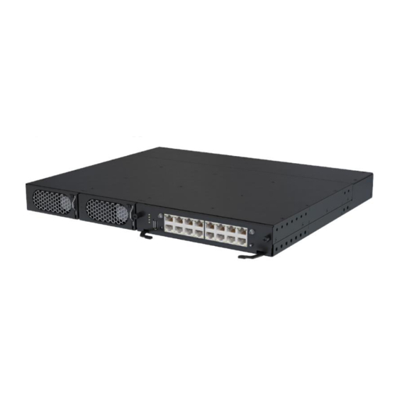
User Manual 3 Device Description Device Description 3.1 ECC800 The ECC800 consists of power supply units (PSUs) and an ECC800 main control module and monitors the equipment and environment in the smart module. Figure 3-1 ECC800 (front view) (1) PSU 1... - Page 23 3 Device Description Figure 3-2 ECC800 (rear view) (1) 53.5V DC_OUT1 (2) 53.5V DC_OUT2 (3) AC_INPUT1 (4) AC_INPUT2 Figure 3-3 ECC800 main control module (side view) (1) SIM card slot (2) Micro-SD card slot ECC800 Specifications Table 3-1 ECC800 environmental specifications Item Specifications –20°...
- Page 24 ECC800 Data Center Controller User Manual 3 Device Description Table 3-2 ECC800 structural specifications Item Specifications Dimensions (L x W x H) 442 mm x 330 mm x 43.6 mm Color Black Installation Can be installed in a 1 U space in a standard...
- Page 25 3G/4G Operation WCDMA BAND: 850 MHz–2100 Frequency GSM: 850 MHz–1900 MHz 3G/4G EIRP (max.) 36 dBm Software version V100 Indicators Table 3-5 Indicators on the ECC800 main control module Indicator Color Name Status Description Green Running status Steady on The power supply is normal, the...
- Page 26 0.5 Hz, on for 1s and then off for 1s). Blinking at The converter application program short intervals is being loaded (the indicator blinks at 4 Hz, on for 0.125s and then off Issue 07 (2020-03-16) Copyright © Huawei Technologies Co., Ltd.
- Page 27 In wireless network (802.15.4) The RF_Z indicator pairing mode, press and hold down is blinking at long the button for 1.2s to 5s to exit the intervals. pairing mode; or the system Issue 07 (2020-03-16) Copyright © Huawei Technologies Co., Ltd.
- Page 28 Then the IP addresses for the ECC800 WAN_1 and WAN_2 ports will restore to the default addresses. Communications Ports The ECC800 provides the following communications ports. Figure 3-4 shows the pins of the RJ45 port. Figure 3-4 RJ45 port pins Issue 07 (2020-03-16) Copyright ©...
- Page 29 Pin 6 Pin 7 Pin 8 Indicator Green Power output indicator indicator Steady on: The 12 V DC output is normal. Off: No 12 V DC output is provided. Issue 07 (2020-03-16) Copyright © Huawei Technologies Co., Ltd.
- Page 30 Table 3-11 DO port pin definitions Item Description Pin sequence Pin 1 Pin 2 Pin 3 12 V DC_OUT Pin 4 Pin 5 Pin 6 DO_NO Pin 7 DO_COM Pin 8 Issue 07 (2020-03-16) Copyright © Huawei Technologies Co., Ltd.
-
Page 31: Southbound Device Introduction
Pin 2 Pin 3 Pin 4 Power Ports The ECC800 provides four power ports, including two AC input ports (AC_INPUT1 and AC_INPUT2) and two DC output ports (DC_OUTPUT1 and DC_OUTPUT2). Table 3-13 provides the power port pin definitions. Table 3-13 Power port pin definitions... - Page 32 Two active 12 V DC, 200 mA AI/DI input ports Temperature Provides two RJ45 ports to connect to six temperature sensors, each RJ45 sensor port port connecting to three temperature sensors. BLINK Provides a BLINK function. button Issue 07 (2020-03-16) Copyright © Huawei Technologies Co., Ltd.
-
Page 33: Smart Eth Gateway
3.2.2 Smart ETH Gateway A smart ETH gateway allows the extension of the 53.5 V DC power supply and FE communication for the ECC800 and can be flexibly deployed in a smart module. Issue 07 (2020-03-16) Copyright © Huawei Technologies Co., Ltd. - Page 34 If you press the BLINK button, the RUN indicator blinks intermittently at button super short intervals (blinking at super short intervals for 0.5s and then off for 0.5s) for 10 seconds. Issue 07 (2020-03-16) Copyright © Huawei Technologies Co., Ltd.
-
Page 35: General Input Unit
Blinking at The smart ETH gateway long successfully registers with intervals the ECC800 and the software runs properly (the indicator blinks at 0.5 Hz, on for 1s and then off for 1s). Blinking at The smart ETH gateway does... - Page 36 BLINK button If you press the BLINK button, the RUN indicator blinks intermittently at super short intervals (blinking at super short intervals for 0.5s and then off for 0.5s) for 10s. Issue 07 (2020-03-16) Copyright © Huawei Technologies Co., Ltd.
-
Page 37: Power Distribution Unit
3.2.4 Power Distribution Unit The power distribution unit integrates the smart ETH gateway and power distribution functions. It provides external power ports for the bus system to collect, count, and report output electrical parameters. Issue 07 (2020-03-16) Copyright © Huawei Technologies Co., Ltd. - Page 38 BLINK button If you press the BLINK button, the RUN indicator blinks intermittently at super short intervals (blinking at super short intervals for 0.5s and then off for 0.5s) for 10s. Issue 07 (2020-03-16) Copyright © Huawei Technologies Co., Ltd.
-
Page 39: Access Control System
Blinking at long The power distribution unit intervals has successfully registered with the ECC800 and the software runs properly (the indicator blinks at 0.5 Hz, on for 1s and then off for 1s). Blinking at The power distribution unit... -
Page 40: Access Actuator
The access actuator is the control component for the aisle door in a smart module. It connects to the ECC800 controller over FE port, wireless networking (802.15.4). It opens the magnetic lock by detecting the card swiping information of the card reader, door open button information, and fire linkage information. - Page 41 One 12 V DC power output that controls magnetic locks, terminal DI input One DI input port for connecting to the door status switch RS485 serial port Two RS485 ports (one route) with the default communications rate of Issue 07 (2020-03-16) Copyright © Huawei Technologies Co., Ltd.
- Page 42 Blinking at long intervals: The access actuator successfully registers with the ECC800 and the software runs properly (the indicator blinks at 0.5 Hz, on for 1s and then off for 1s). Blinking at short intervals: The...
- Page 43 Table 3-25 lists the LOCK/GND/GATE/COM port pin definitions. Table 3-25 LOCK/GND/GATE/COM port pin definitions Item Description LOCK/GND (control LOCK 12 V_OUT magnetic locks) pin sequence GATE/COM (door status) GATE pin sequence Issue 07 (2020-03-16) Copyright © Huawei Technologies Co., Ltd.
-
Page 44: Fingerprint And Card Reader With A Keypad
Fingerprint reader The indicator blinks The indicator turns on (white). white twice and then turns on (red). Issue 07 (2020-03-16) Copyright © Huawei Technologies Co., Ltd. -
Page 45: Fingerprint And Card Reader
(2) LED indicator Table 3-28 Fingerprint and card reader Item Specifications Dimensions (L x W x H) 156 mm x 53 mm x 38 mm Rated operating voltage 12 V DC ± 5% Issue 07 (2020-03-16) Copyright © Huawei Technologies Co., Ltd. - Page 46 Card swiping LED indicator The indicator blinks The indicator blinks blue, red, and blue blue, red, and blue in order. in order. Buzzer sounds The buzzer sounds The buzzer sounds once. once. Issue 07 (2020-03-16) Copyright © Huawei Technologies Co., Ltd.
-
Page 47: Card Reader With A Keypad
12 V DC Operating current Static standby current 80 mA, dynamic operating current (card swiping, key pressing) 150 mA, minimum input current 12 V DC/300 mA Communications mode Wiegand communications port Issue 07 (2020-03-16) Copyright © Huawei Technologies Co., Ltd. -
Page 48: Magnetic Lock
Figure 3-15 Magnetic lock for a sliding door 3.2.5.2 Cabinet Access Control System The cabinet access control system applies to cabinets in the aisle containment to ensure data and device security. Issue 07 (2020-03-16) Copyright © Huawei Technologies Co., Ltd. - Page 49 The cabinet door can be opened with only the password and without the key. The user can set a password. A password should contain at least three digits. The password can be reset if the user forgot it. Issue 07 (2020-03-16) Copyright © Huawei Technologies Co., Ltd.
-
Page 50: Ac Actuator
Figure 3-18 AC actuator (1) AC OUT2 port (2) AC OUT1 port (3) AC IN port (4) Status indicator (5) BLINK button (6) AI/DI dry (7) COM1–2 RS485 contact port Issue 07 (2020-03-16) Copyright © Huawei Technologies Co., Ltd. - Page 51 Blinking at The AC actuator successfully long intervals registers with the ECC800 and the software runs properly (the indicator blinks at 0.5 Hz, on for 1s and then off for 1s). Blinking at The communication is...
-
Page 52: Skylight Actuator
The skylight actuator controls the rotating skylight on the aisle containment of the smart module through the alarm linkage information from the fire extinguishing system or the control information from the upper computer. The skylight actuator supports E-labels and wireless networking (802.15.4). Issue 07 (2020-03-16) Copyright © Huawei Technologies Co., Ltd. - Page 53 Hold down the button for less than 1 second to start blinking. Hold down the button for 1–5 seconds to search for a network and start networking. Hold down the button for more than 6 seconds to clear network Issue 07 (2020-03-16) Copyright © Huawei Technologies Co., Ltd.
- Page 54 Blinking at The skylight actuator long intervals successfully registers with the ECC800 and the software runs properly (the indicator blinks at 0.5 Hz, on for 1s and then off for 1s). Blinking at The communication fails or the...
-
Page 55: Multi-Functional Sensor
D pin sequence 3.2.8 Multi-Functional Sensor A multi-functional sensor integrates the temperature and humidity (T/H) sensor and smoke sensor. The multi-functional sensor can connect to the ECC800 over FE or wireless communication. Issue 07 (2020-03-16) Copyright © Huawei Technologies Co., Ltd. - Page 56 Hold down the button for 1–5 seconds to search for a network and start networking. Hold down the button for more than 6s to clear network parameters. Smoke sensor Supported test button Issue 07 (2020-03-16) Copyright © Huawei Technologies Co., Ltd.
- Page 57 Module running Blinking at The multi-functional sensor status indicator long intervals successfully registers with the ECC800 and the software runs properly (the indicator blinks at 0.5 Hz, on for 1s and then off for 1s). Blinking at The multi-functional sensor...
-
Page 58: Smoke Detector
< 95% RH (non-condensing) Dimensions Diameter: 112 mm, height: 41 mm 3.2.10 Temperature Sensor The temperature sensor (the code: 33010348) is used for the surface temperature measure, industrial process control, measurement instrument, etc. Issue 07 (2020-03-16) Copyright © Huawei Technologies Co., Ltd. -
Page 59: Alarm Beacon
Figure 3-23 Alarm beacon Table 3-41 Structural specifications of an alarm beacon Item Specifications Dimensions (L x W x H) 130 mm x 75 mm x 55 mm Issue 07 (2020-03-16) Copyright © Huawei Technologies Co., Ltd. -
Page 60: Water Sensor
A water sensor detects water on the floor in real time and generates an alarm when water is detected. 3.2.12.1 WLDS600 Water Sensor The WLDS600 water sensor with the BOM number of 33010465 consists of a water detection cable, a water detector, and a conversion cable. Issue 07 (2020-03-16) Copyright © Huawei Technologies Co., Ltd. - Page 61 Specification Detection cable 0–200 m Operating 12 V to 24 V DC voltage –20° C to 70° C Operating temperature –20° C to 80° C Storage temperature Humidity 10%–80% RH (non-condensing) Issue 07 (2020-03-16) Copyright © Huawei Technologies Co., Ltd.
-
Page 62: Wlds900 Water Sensor
Table 3-44 WLDS900 water sensor specifications Item Specification Operating 12 V DC (9–16 V DC) voltage –20° C to +70° C Operating temperature –40° C to +85° C Storage temperature Humidity 10%–80% RH (non-condensing) Issue 07 (2020-03-16) Copyright © Huawei Technologies Co., Ltd. -
Page 63: Electrode Water Sensor
10 years 3.2.13 WiFi Converter The WiFi converter is used in a smart module to convert POE signals into WiFi signals for communicating with devices such as the pad and mobile phone. Issue 07 (2020-03-16) Copyright © Huawei Technologies Co., Ltd. - Page 64 WPS function: If you choose Advanced settings > WPS connection on the WLAN of the intelligent device and press the WPS button on the WiFi converter at the same time, the intelligent device will quickly connect to the WiFi hotspot of the micro-module. Issue 07 (2020-03-16) Copyright © Huawei Technologies Co., Ltd.
-
Page 65: Wifi Module
Blinking at The WiFi converter long intervals status successfully registers with the indicator ECC800 and the software runs properly (the indicator blinks at 0.5 Hz, on for 1s and then off for 1s). Blinking at The WiFi converter fails to... -
Page 66: Eth Converter
5%–90% RH (non-condensing) Power < 0.8 W 3.2.15 ETH Converter The ETH converter is used to convert the Modbus–RTU protocol or CAN protocol to the Modbus-MAC protocol for connecting to the POE bus. Issue 07 (2020-03-16) Copyright © Huawei Technologies Co., Ltd. - Page 67 If you press the BLINK button, the RUN indicator blinks intermittently at super short intervals (blinking at super short intervals for 0.5s and then off for 0.5s) for 10 seconds. E-label Supported Issue 07 (2020-03-16) Copyright © Huawei Technologies Co., Ltd.
-
Page 68: Pad
1s). Blinking at The communication fails or short the ETH converter fails to intervals register with the ECC800 (the indicator blinks at 4 Hz, on for 0.125s and then off for 0.125s). Blinking The indicator blinks at super short intervals for 0.5s... - Page 69 Micro-USB port that supports charging and synchronization with PC data Battery Materials: Li-polymer Capacity: 4800 mAh WiFi connection/Web page browse time: about 6.5 hours Power adapter charge time: about 6 hours Issue 07 (2020-03-16) Copyright © Huawei Technologies Co., Ltd.
-
Page 70: T/H Sensor
The T/H sensor uses an RJ45 connector. Figure 3-32 Pins of an RJ45 connector Table 3-53 Pin description of an RJ45 connector Description Pin 1 Pin 2 Pin 3 Pin 4/5/6/7 Reserved Pin8 Issue 07 (2020-03-16) Copyright © Huawei Technologies Co., Ltd. -
Page 71: T/H Sensor (Bom Number:02310Nbs)
3.2.17.2 T/H Sensor (BOM number:02310NBS) Figure 3-33 Appearance (1) Status indicator (2) RS485_IN (3) RS485_OUT (4) Address DIP switch The RS485 communications ports of the T/H sensor use RJ11 (6P6C) connectors. Issue 07 (2020-03-16) Copyright © Huawei Technologies Co., Ltd. -
Page 72: Intelligent Battery Monitoring System
(SOC) and state of health (SOH) of batteries and battery strings and estimates the battery health status accordingly, supports battery tripping management, and uploads data to the management unit through COM or POE ports. Issue 07 (2020-03-16) Copyright © Huawei Technologies Co., Ltd. -
Page 73: Cim
CIM is a battery information collection module. It collects battery status data from the downstream BIM groups through wireless communication, and sends the data to the ECC, UPS, and the third-party network management system (NMS) through COM or POE ports. Issue 07 (2020-03-16) Copyright © Huawei Technologies Co., Ltd. - Page 74 (7) RF_Z antenna port (8) BCB_1–BCB_4 (9) BCB_OUT and BCB_IN ports ports (10) Networking switch (11) PWR indicator (12) RUN indicator (13) ALM indicator (14) RF_Z indicator (15) Delivered antenna Issue 07 (2020-03-16) Copyright © Huawei Technologies Co., Ltd.
- Page 75 Figure 3-39 Power port pins Table 3-57 12 V, 2 A port pin definitions Definition Description – In this scenario, an external power module is adopted to supply 12 V DC operating voltage. Issue 07 (2020-03-16) Copyright © Huawei Technologies Co., Ltd.
- Page 76 Table 3-59 POE port pin definitions Definition Description Supports power supply through the POE port. The TX– terminal is an RJ45 terminal with an indicator. 4, 5 P45_P1 RX– 7, 8 P78_P1 Issue 07 (2020-03-16) Copyright © Huawei Technologies Co., Ltd.
- Page 77 Initial Status Remarks Description Description Dry contact Open: The Open Dry contact input signal dry contact input and output – input is signal open. Closed: The dry contact input is Issue 07 (2020-03-16) Copyright © Huawei Technologies Co., Ltd.
- Page 78 Hall effect sensor is not enough, use multiple Hall effect sensors to monitor the current of one battery string. The CIM supports the sum of the monitoring results of multiple Hall effect sensors, which is set through Multi-Hall cur. setting. Issue 07 (2020-03-16) Copyright © Huawei Technologies Co., Ltd.
- Page 79 Grounded Disconnected Receives the BCB connects whether the : BCB to the signal output cascaded BCBs connected commands port. connect to the sent by the signal input UPS and Disconne Issue 07 (2020-03-16) Copyright © Huawei Technologies Co., Ltd.
- Page 80 Secondary side ground signal for tripping. 12 V: There is a driving signal for tripping. DIP Switch Table 3-65 DIP switch description Definition Description ADDR_1 RS485 communications address setting ADDR_2 ADDR_3 ADDR_4 Issue 07 (2020-03-16) Copyright © Huawei Technologies Co., Ltd.
- Page 81 Alarm indicator Steady on The actual number of Check the value of online devices is less than BIM number, the the value of BIM number. BIM cable connection, and the BIM indicators. Issue 07 (2020-03-16) Copyright © Huawei Technologies Co., Ltd.
- Page 82 10s but less than 20s. BIMs). Default Button Table 3-68 Default button description Name Definition Function Default button Hold down the button Reset to the default IP address (192.168.0.10) for more than 10 seconds. Issue 07 (2020-03-16) Copyright © Huawei Technologies Co., Ltd.
-
Page 83: Bim
The BIM is not faulty. Steady on The BIM is faulty. Communication with the CIM times out. No network is connected. (The BIM is waiting to connect to a Issue 07 (2020-03-16) Copyright © Huawei Technologies Co., Ltd. - Page 84 Initializes the network parameters if there is a network. Button holding Hold down the button Clears the current network and resets the down for more than 5 wireless module; disconnect the network. seconds. Issue 07 (2020-03-16) Copyright © Huawei Technologies Co., Ltd.
-
Page 85: Ui Description
Step 1 Connect a network cable between the PC network port and the WAN_1 port (protected by a security mechanism) on the ECC800. Table 4-1 Default IP addresses for the WAN and LAN ports on the ECC800 Port Default IP Address WAN_1 192.168.1.10... - Page 86 Step 3.3 Step 3.4. If the ECC800 connects to the Internet, and the PC in a LAN accesses the Internet over a proxy server, do not perform Step 3.3 Step 3.4. Otherwise, you will fail to access the ECC800.
-
Page 87: Webui Description
Then set the security level of the trusted site to the lowest. When switching between different versions of the ECC800 on your PC, you are advised to clear the historical Internet Explorer cache. Failing to do so may cause some information missed or exception after login. - Page 88 View and manage the layout view of devices. View the system PUE in a dashboard and the system trend curve. Active Alarms Query active alarms. Multi-Module View the status of each cascaded ECC800. Monitoring Issue 07 (2020-03-16) Copyright © Huawei Technologies Co., Ltd.
- Page 89 Monitor the device running information in real time, set device running parameters, and control the device running. For example, set smart cooling product parameters, delete devices failing in communication, and set AI/DI device parameters. Issue 07 (2020-03-16) Copyright © Huawei Technologies Co., Ltd.
- Page 90 Query and set device performance parameters. Configure multi-module settings to cascade up to three ECC800s. Maintenance Upgrade the software of the ECC800 and southbound devices and download the app. (App installation package 16.5 M) Query the version and e-labels. ...
-
Page 91: App Introduction
Figure 4-6 Mobile phone app menu hierarchy The actual menu hierarchy prevails. Table 4-4 Mobile phone app functions Screen Function Home View the device layout diagram, and tap a device icon in the layout Issue 07 (2020-03-16) Copyright © Huawei Technologies Co., Ltd. -
Page 92: Pad App
Upgrade software. Maintain the system. For example, import and export data, view network parameters, synchronize device parameters, and view the version information. Log out. 4.2.2 Pad App Figure 4-7 Home Issue 07 (2020-03-16) Copyright © Huawei Technologies Co., Ltd. - Page 93 View operation logs. Upgrade software. Maintain the system. For example, view the version information, import or export a configuration file, view network parameters, synchronize device parameters, and log out. Issue 07 (2020-03-16) Copyright © Huawei Technologies Co., Ltd.
-
Page 94: Power-On Commissioning
(Optional) If the system type is inconsistent with the type of the smart module, perform the following operations. The system type FusionModule2000 is used as an example. Issue 07 (2020-03-16) Copyright © Huawei Technologies Co., Ltd. -
Page 95: Setting And Adding Devices
Step 2 Choose System Info > Settings, enter the user name admin and password 000001, and then . In the displayed dialog box for confirming the password, tap OK. If you enter incorrect passwords for three consecutive times, you will be locked out for 5 minutes. Issue 07 (2020-03-16) Copyright © Huawei Technologies Co., Ltd. -
Page 96: How To Set And Add A Ups2000-G
Step 3 Choose Settings > Communication, and set IP address assign to Automatic(DHCP). Step 4 Tap to go back to the main menu screen. After setting parameters for the integrated UPS, the ECC800 discovers the access from the integrated UPS automatically. ----End 5.3.2 How to Set and Add a UPS2000-G? - Page 97 UPS2000-G based on the actual situation. Click Test Connect to check whether the UPS2000-G connects to the ECC800 properly. − If the UPS2000-G connects to the ECC800 properly, click Confirm. The connected devices are displayed in the Number of connected devices list.
-
Page 98: How To Set And Add A Ups5000-E
The section describes how to add a UPS2000-G in a single UPS scenario. In a parallel UPS scenario, if the common communications address of the Modbus card is added to the ECC800, all UPS2000-Gs can be connected to the ECC800. -
Page 99: How Do I Set And Add A Sunrise Scu-20K
UPS5000-E based on the actual situation. Click Test Connect to check whether the UPS5000-E connects to the ECC800 properly. If the UPS5000-E connects to the ECC800 properly, click Confirm. The connected −... - Page 100 In this example, Device address is set to 2. During actual configuration, set the device address based on the actual situation. Click Test Connect to check whether the SUNRISE-SCU-20K connects to the ECC800 properly. − If the SUNRISE-SCU-20K connects to the ECC800 properly, click Confirm. The connected devices are displayed in the Number of connected devices list.
-
Page 101: Setting Netcol5000-C030 Parameters (Over Modbus Tcp)
Choose Settings > Comm Settings > Modbus Settings, and set Connection mode to Server, Server encryption to Enable. After setting parameters for the NetCol5000-C030, the ECC800 discovers the access from the air conditioner automatically. The earlier version has Protocol setting on the screen. The actual screen prevails. - Page 102 In this example, Device address is set to 1. During actual configuration, set the device address for the NetCol5000-C030 based on the actual situation. Click Test Connect to check whether the NetCol5000-C030 connects to the ECC800 properly. − If the NetCol5000-C030 connects to the ECC800 properly, click Confirm. The connected devices are displayed in the Number of connected devices list.
-
Page 103: How To Set Netcol5000-A025 Parameters
Choose Settings > Comm Settings > Modbus Settings, and set Connection mode to Server and client, Server encryption to Enable. After the NetCol5000-A025 parameters are set, the ECC800 can automatically identify the automatic access of the NetCol5000-A025. Step 2 Set the running parameters and control parameters for the 25 kW smart cooling product on the ECC800 WebUI. -
Page 104: How Do I Set Netcol5000-A042 Parameters
Choose Settings > Comm Settings > Modbus Settings, and set Connection mode to Server and client, Server encryption to Enable. After the NetCol5000-A042 parameters are set, the ECC800 can automatically identify the automatic access of the NetCol5000-A042. Step 2 Set the running parameters and control parameters for the 42 kW smart cooling product on the ECC800 WebUI. -
Page 105: Setting And Adding A Pdu8000 Or Integrated Pdu (Over Modbus-Tcp)
Comm address based on site requirements. The earlier version has Protocol setting on the screen. The actual screen prevails. Step 2 Set the running parameters and control parameters for the NetCol5000-A035 on the ECC800 WebUI. The NetCol5000-A035 connects to the smart ETH gateway through the ETH converter to communicate with the ECC800. -
Page 106: How To Set And Add A Pdu8000 (Over Modbus Rtu)
ECC800 Data Center Controller User Manual 5 Power-On Commissioning Context The method of connecting the PDU8000 to the ECC800 is the same as that for the integrated PDU. Connecting the integrated PDU to the ECC800 by following the instructions in this section. Procedure Step 1 Set the PDU8000 monitoring parameters. - Page 107 If the PDU8000 connects to the ECC800 properly, click Confirm. The connected devices are displayed in the Number of connected devices list. − If the PDU8000 does not connect to the ECC800 properly, check whether the cable between the PDU8000 and the ECC800 is connected properly, whether the Issue 07 (2020-03-16)
-
Page 108: How To Set And Add A Pdu2000
One end of the straight-through cable has been connected to the COM 1 or COM 2 port on the PDU2000, and the other end has been connected to the COM port on the ECC800 collector, rack environment unit, or ETH converter. - Page 109 The display of a single-phase module is used as an example. After the PDU2000-M (H) is powered on, press MENU. The LCM displays − Press MENU again to access the device communications address screen. − Issue 07 (2020-03-16) Copyright © Huawei Technologies Co., Ltd.
- Page 110 Number of connected devices list. − If the PDU2000 does not connect to the ECC800 properly, check whether the cable between the PDU2000 and the ECC800 is connected properly, whether the PDU2000 and ECC800 are running properly, and whether the input parameters are consistent with the PDU2000 parameters.
-
Page 111: Commissioning The Smart Busway
If the smart busway is used, general input units and power distribution units communicate with the ECC800 using the Modbus-MAC protocol. After the general input units and power distribution units properly connect to the ECC800, the ECC800 automatically identifies the units. -
Page 112: How To Set And Add An Ats
5.3.14 How to Set and Add an ATS? Prerequisites One end of the straight-through cable has been connected to the COM port on the ATS, and the other end has been connected to the COM port on the ECC800 collector, rack environment unit, or ETH converter. Context The ATS (ABB) model is OMD800. -
Page 113: How To Set And Add A Pmac625 Ac Meter
Prerequisites One end of the straight-through cable has been connected to the RS485 port on the PMAC625 AC meter, and the other end has been connected to the COM port on the ECC800. Issue 07 (2020-03-16) Copyright © Huawei Technologies Co., Ltd. - Page 114 , modify the communications address value (ranging from 1 to 247) by pressing , and then press to save the setting. Figure 5-8 Communications address of the PMAC625 Step 2 Add a PMAC625. Issue 07 (2020-03-16) Copyright © Huawei Technologies Co., Ltd.
-
Page 115: How To Set And Add A Pmac615 Ac Meter
Prerequisites One end of the straight-through cable has been connected to the RS485 port on the PMAC615 AC meter, and the other end has been connected to the COM port on the ECC800. Context The model of the single-phase AC meter for the lighting control box is PMAC615. - Page 116 If the PMAC615 connects to the ECC800 properly, click Confirm. The connected − devices are displayed in the Number of connected devices list. If the PMAC615 does not connect to the ECC800 properly, check whether the cable − between the PMAC615 and the ECC800 is connected properly, whether the Issue 07 (2020-03-16) Copyright ©...
-
Page 117: How To Set And Add A Pdc Dc Meter
Prerequisites One end of the straight-through cable has been connected to the RS485 port on the PDC DC meter, and the other end has been connected to the COM port on the ECC800. Context The model of the PDC is PDU8000-0630DCV5-HVA002 and the BOM number is 02403121. -
Page 118: Setting And Adding An Independent Deployment Ai_Di Unit
Number of connected devices list. − If the PDC DC meter does not connect to the ECC800 properly, check whether the cable between the PDC DC meter and the ECC800 is connected properly, whether the PDC DC meter and ECC800 are running properly, and whether the input parameters are consistent with the PDC DC meter parameters. -
Page 119: Adding A Ip Device
----End 5.3.19 Adding a IP Device Prerequisites A IP device is connected to the ECC800 over a switch. The device and ECC800 have been powered on. You have obtained the IP address of the IP device. Issue 07 (2020-03-16) -
Page 120: Commissioning The Ac Actuator (Wireless Networking)
IP devices, such as ATMs, are devices with IP attributes in an equipment room or site. By adding a IP device, you connect the device to the ECC800 in the same network so that the ECC800 monitors the device status. If the IP device is offline, the ECC800 will report a disconnection alarm on its WebUI. - Page 121 That is, the RF_Z indicators on the ECC800 and AC actuator are both steady green. If the RF_Z indicator on the ECC800 is not steady green, hold down the SW button on the ECC800 for more than 6 seconds to make the ECC800 enter non-networking status. ...
-
Page 122: Commissioning Sensors
Start counting time immediately when smoke is smoky environment. entering the hole. After about 30 seconds, the red ALM indicator turns on, and the app or WebUI Smoke generation methods: Issue 07 (2020-03-16) Copyright © Huawei Technologies Co., Ltd. - Page 123 After the commissioning is complete, clean up dust. Issue 07 (2020-03-16) Copyright © Huawei Technologies Co., Ltd.
-
Page 124: Commissioning A Smoke Sensor
Procedure Step 1 Set smoke sensor parameters. In this example, the smoke sensor is connected to the AI/DI_3 port on the ECC800. Log in to the ECC800 WebUI as an administrator. Choose System Settings > Signal Name Modify. The Batch Signal Configuration page is displayed. -
Page 125: Commissioning A Smoke Sensor (Connected To The Ai/Di Port On The Skylight Actuator)
5 Power-On Commissioning On the query result tab page, set the new signal name of AI/DI_3 to Smoke and click Submit. Choose Monitoring > System > ECC800 > Running Parameters > AI/DI_3 Port Settings. Set Smoke sensor to Enable and click Submit. -
Page 126: Commissioning A Water Sensor
Step 1 Set water sensor parameters. In this example, the water sensor is connected to the AI/DI_1 port on the ECC800. The default alarm severity of the AI/DI port is Minor. If you want to change the alarm severity, see How Should I Configure Alarm Parameters. -
Page 127: Commissioning A Wlds600 Water Sensor
Step 1 The default communications address 1 of the water sensor is used for connecting to the ECC800. Step 2 Add a water sensor. In this example, the water sensor is connected to the COM1 port on the ECC800. Log in to the ECC800 WebUI as an administrator. Add the water sensor. -
Page 128: Commissioning A Electrode Water Sensor
Procedure Step 1 Set water sensor parameters. In this example, the water sensor is connected to the AI/DI_3 port on the ECC800. Log in to the ECC800 WebUI as an administrator. Choose System Settings > Signal Name Modify. The Batch Signal Configuration page is displayed. -
Page 129: Commissioning A Door Status Sensor
In this example, the door status sensor is connected to the AI/DI_1 port on the independent deployment AI_DI 1. Log in to the ECC800 WebUI as an administrator. Choose System Settings > Signal Name Modify. The Batch Signal Configuration page is displayed. -
Page 130: Commissioning A Door Status Sensor (Connected To The Ai/Di Port On The Rack Environment Unit)
In this example, the door status sensor is connected to the AI/DI_1 port on the rack environment unit 1. Log in to the ECC800 WebUI as an administrator. Choose Monitoring > IT Cabinet > IT Cabinet 1 > Cabinet Collector1 > Running Parameters >... -
Page 131: Commissioning A Temperature Sensor
Procedure Step 1 Set temperature sensor parameters. In this example, the temperature sensor is connected to the AI/DI_2 port on the ECC800. Log in to the ECC800 WebUI as the administrator. Choose System Settings > Signal Name Modify. The Batch Signal Configuration page is displayed. -
Page 132: Commissioning A Temperature Sensor (Connected To The Ntc Port On The Rack Environment Unit)
Go to the LCD screen of the T/H sensor. Press SET to go to the ADD screen, and set the device address to 1 by pressing + or –. Step 2 Add a T/H sensor. Log in to the ECC800 WebUI as an administrator. Add a T/H sensor. Table 5-31 Adding a T/H sensor... -
Page 133: Commissioning A T/H Sensor (Bom Number:02310Nbs)
Number of connected devices list. − If the T/H sensor does not connect to the ECC800 properly, check whether the cable between the T/H sensor and the ECC800 is connected properly, whether the T/H sensor and ECC800 are running properly, and whether the input parameters are consistent with the T/H sensor parameters. - Page 134 Number of connected devices list. − If the T/H sensor does not connect to the ECC800 properly, check whether the cable between the T/H sensor and the ECC800 is connected properly, whether the T/H sensor and ECC800 are running properly, and whether the input parameters are consistent with the T/H sensor parameters.
-
Page 135: Commissioning An Access Control Device And A Cabinet Electronic Lock
Access Right Management page. The added or modified user accounts and rights are saved only in the ECC800 main control module. The modified rights take effect in the access control device only after you click Synchronize Permission on the Access Right Management page. - Page 136 Click Add to enter the page for adding permissions. Click and select the user whose access permissions need to be set, and set the Door, Authorization mode, Cabinet lock, and the permission validity period. Issue 07 (2020-03-16) Copyright © Huawei Technologies Co., Ltd.
- Page 137 An authorized IC card can be used to open both the access control device and the cabinet magnetic lock. Figure 5-12 Adding access permissions In the displayed prompt box, click OK. Click Synchronize Permission, select the modified access control devices, and click Start Synchronization. Issue 07 (2020-03-16) Copyright © Huawei Technologies Co., Ltd.
- Page 138 If the access control system uses a Card and password reader, choose Monitoring > Aisle > Access Actuator Group > Access Actuator n on the ECC800 WebUI, click Running Parameters, and set Logical level configuration for reader removed of the corresponding card reader to High level alarm.
-
Page 139: Commissioning The Exit Button, Emergency Button, And Magnetic Lock
Normal Connection Status Attempt to open the door by pressing the The aisle door is opened successfully. exit button when the aisle door is closed. Step 2 Check functions of the emergency button. Issue 07 (2020-03-16) Copyright © Huawei Technologies Co., Ltd. -
Page 140: Commissioning An Emergency Door Release Button
NC and COM or terminals NC and COM or NO and COM on the NO and COM on the emergency door release button. emergency door release button. ----End Issue 07 (2020-03-16) Copyright © Huawei Technologies Co., Ltd. -
Page 141: Commissioning Cims And Bims
If CIMs and battery interface modules (BIMs) are installed, perform the following steps to commission. Procedure Step 1 Log in to the ECC800 WebUI as an administrator. Step 2 Choose Monitoring > Power Distribution > CIM > Running Parameters. Step 3 Set CIM single battery qty., Batt installation time, Battery string capacity, Current source, and Battery string No.. -
Page 142: Commissioning The Cameras And Vcn500 (Smart Eth Gateway Networking Scenario)
CIMs and BIMs. ----End 5.7 Commissioning the Cameras and VCN500 (Smart ETH Gateway Networking Scenario) A maximum of three cameras can be connected in the smart ETH gateway networking scenario. Issue 07 (2020-03-16) Copyright © Huawei Technologies Co., Ltd. -
Page 143: Configuring The Vcn500
To ensure the normal operating of the ECC800, avoid high data traffic, such as the concurrent display of dynamic monitoring of cameras and VCN500 video playback. To ensure the normal operating of the ECC800, you can view the videos from a maximum of two IPC6325-WD-VR cameras concurrently. 5.7.1 Configuring the VCN500 Prerequisites For details about the VCN500 hardware description and installation, see the "Quick Start"... - Page 144 After the first login, change the password in time to ensure account security and prevent unauthorized network attacks, such as data tampering. Huawei will not be liable for any security issues caused by your failure to change the preset password in time or password loss after changing.
-
Page 145: Commissioning Ipc6325 Cameras
(Dynamic Host Configuration Protocol). In the network, the IPC6325 camera automatically obtains an IP address in the same IP address segment as the ECC800 after the ECC800 and IPC6325 are powered on. Therefore, you need to reset the IPC6325 camera IP address before commissioning an IPC6325 camera. - Page 146 (Optional) In the scenario without the ring network of the smart ETH gateway, use a network cable to connect a PC to an idle POE port of the smart ETH gateway. Configure the PC IP address and IP address of the LAN port on the ECC800 in the same network segment.
- Page 147 Internal IP: Enter the internal IP address, that is, the IP address of the camera (for example, 192.168.248.50). Link: Enter the external IP address of the camera (for example, https://external IP address of the camera). Figure 5-19 Adding video information Issue 07 (2020-03-16) Copyright © Huawei Technologies Co., Ltd.
- Page 148 5.7.4 Commissioning IPC6325 Camera (SD Card Configured). Set camera stream type, primary stream, and secondary stream 1 parameters. Set coding protocol to H.264. Figure 5-20 Setting primary stream parameters Issue 07 (2020-03-16) Copyright © Huawei Technologies Co., Ltd.
-
Page 149: Adding A Camera On The Vcn
The version number is subject to the Quick Start delivered with the VCN. The description and link in this document are for reference only. Procedure Step 1 Install the Client/Server (C/S) client. Issue 07 (2020-03-16) Copyright © Huawei Technologies Co., Ltd. -
Page 150: Commissioning Ipc6325 Camera (Sd Card Configured)
After the first login, change the password in time to ensure account security and prevent unauthorized network attacks, such as data tampering. Huawei will not be liable for any security issues caused by your failure to change the preset password in time or password loss after changing. - Page 151 Table 5-45 Camera configuration parameters Condition Result Coding Resolution Frame Rate I-frame Minimum Supported Protocol Interval Required Bit Video Storage Rate Duration (h) H.265 1080P H.264 1080P H.265 720P 0.8M H.264 720P Issue 07 (2020-03-16) Copyright © Huawei Technologies Co., Ltd.
- Page 152 Step 3 Select Enable, add motion detection areas, set motion detection parameters, and click Save. Figure 5-24 Setting motion detection parameters Step 4 Set the deployment policy. Figure 5-25 Setting the deployment policy Step 5 Set the alarm linkage policy. Issue 07 (2020-03-16) Copyright © Huawei Technologies Co., Ltd.
-
Page 153: Commissioning Cameras And A Vcn (Lan Switch Networking Scenario)
Figure 5-27 Video system networked over a LAN switch 5.8.1 Configuring the VCN500 Prerequisites For details about the VCN500 hardware description and installation, see the "Hardware Guide" in the VCN500 V100R002C20 Product Documentation. For details about the VCN500 Issue 07 (2020-03-16) Copyright © Huawei Technologies Co., Ltd. - Page 154 After the first login, change the password in time to ensure account security and prevent unauthorized network attacks, such as data tampering. Huawei will not be liable for any security issues caused by your failure to change the preset password in time or password loss after changing.
-
Page 155: Commissioning Ipc6325 Cameras
Configure the PC IP address and the camera IP address in the same network segment. Enter the camera IP address (192.168.0.120 by default) in the address bar of the Internet Explorer and press Enter button. Issue 07 (2020-03-16) Copyright © Huawei Technologies Co., Ltd. - Page 156 Subnet mask, and Gateway IP address for the camera according to the site plan. Set camera stream type, primary stream, and secondary stream 1 parameters. Set coding protocol to H.264. Issue 07 (2020-03-16) Copyright © Huawei Technologies Co., Ltd.
- Page 157 ECC800 Data Center Controller User Manual 5 Power-On Commissioning Figure 5-30 Setting primary stream parameters Issue 07 (2020-03-16) Copyright © Huawei Technologies Co., Ltd.
-
Page 158: Adding A Camera On The Vcn500
Procedure Step 1 Install Client/Server (C/S) client. Obtain HW_IVS_Client.exe file from the CD-ROM delivered with the VCN50. You can also log in to http://support.huawei.com/enterprise/ and search Client Package.zip to download the corresponding version software. Issue 07 (2020-03-16) Copyright © Huawei Technologies Co., Ltd. -
Page 159: Commissioning Ipc6325 Camera (Sd Card Configured)
After the first login, change the password in time to ensure account security and prevent unauthorized network attacks, such as data tampering. Huawei will not be liable for any security issues caused by your failure to change the preset password in time or password loss after changing. - Page 160 Choose Settings > System Configuration > Storage Management. The Storage Management page is displayed, format the SD card. Figure 5-33 Format the SD card Set the camera stream type and primary stream parameters. Issue 07 (2020-03-16) Copyright © Huawei Technologies Co., Ltd.
- Page 161 (h) H.265 1080P H.264 1080P H.265 720P 0.8M H.264 720P H.265 720P 0.6M H.264 720P 0.8M Select Enable, add motion detection areas, set motion detection parameters, and click Save. Issue 07 (2020-03-16) Copyright © Huawei Technologies Co., Ltd.
- Page 162 5 Power-On Commissioning Figure 5-35 Setting motion detection parameters Set the deployment policy. Figure 5-36 Setting the deployment policy Set the alarm linkage policy. Figure 5-37 Setting the alarm linkage policy ----End Issue 07 (2020-03-16) Copyright © Huawei Technologies Co., Ltd.
-
Page 163: Creating A Smart Module Plan View
Hold down the BLINK button on a device for less than 1s to report the blinking status to the ECC800. The corresponding device icon in the WebUI plan view blinks. Drag a device in the WebUI plan view. The RUN indicator on the corresponding device blinks intermittently at super short intervals. - Page 164 Step 3 Hold down the BLINK button on a device such as a smart ETH gateway for less than 1s to report the blinking status to the ECC800. The corresponding device icon in the WebUI plan view blinks. Check that the device positions and types in the plan view are consistent with the actual situation by delivering the blinking command.
-
Page 165: Commissioning Alarm Notification
To implement alarm notification by email, the following conditions must be met: The ECC800 is connected to a network with n email server through a WAN port. Both the Internet and local area network (LAN) are supported. The ECC800 supports only SMS notification service but not data service by using the 3G module. - Page 166 Successfully to send the test short message. is displayed. If it is unavailable, Failed to send the test short message. is displayed. Check whether the receiver's mobile phone parameters for receiving short messages are correctly set. Issue 07 (2020-03-16) Copyright © Huawei Technologies Co., Ltd.
- Page 167 User Manual 5 Power-On Commissioning Figure 5-42 SMS setting page Step 9 Set the Alarm notification delay time and Add Alarm Notification parameters. Figure 5-43 Setting the Alarm notification delay time parameter Issue 07 (2020-03-16) Copyright © Huawei Technologies Co., Ltd.
- Page 168 Settings. Mobile Phone Number can be selected after it is added in SMS Settings. Step 10 Click Confirm to access the re-authentication page. Enter Login password and click Submit. ----End Follow-up Procedure To modify or delete the email parameter settings, click Modify or Delete. Issue 07 (2020-03-16) Copyright © Huawei Technologies Co., Ltd.
-
Page 169: Feature Description
6.1.1 Linking the Smoke Alarm with the Alarm Beacon Prerequisites The alarm beacon is connected to the DO port on the ECC800. Context This section describes how to set an alarm linkage by linking output dry contact of the smoke alarm on the multi-functional sensor to the DO2 port. -
Page 170: Linking The Ai/Di Alarm With The Alarm Beacon
Procedure Step 1 Choose System Settings > Alarm Parameter Settings > Alarm Linkage. Step 2 Select ECC800 for Device Type, select Device Type or Device for Linkage type, and click Confirm. Select ECC800 from the Device Name list if you have selected Device for Linkage type, and click Confirm. -
Page 171: Setting Ecc800 Cascading
Context A maximum of three ECC800s can be cascaded. After the IP addresses of other smart module ECC800s in the room are added to an ECC800, their active alarms and PUE data can be displayed and viewed. You can click links on the cascading management page of the master ECC800 to display the login pages of the other ECC800s. -
Page 172: Optional) Icooling Function
Step 5 Choose Home > Multi-Module Monitoring. The information about the cascaded ECC800s is displayed. Figure 6-2 ECC800 cascading page Step 6 (Optional) Click the alarm bubble in the Active alarms area in a smart module to view the corresponding active alarm information. - Page 173 Smart cooling product should be placed face to face. − An integrated UPS, integrated PDC, or precision PDC is deployed inside the smart module. The ECC800 can collect statistics on IT branch power information for each IT cabinet and network cabinet. −...
-
Page 174: Pue Configuration Management
In this case, the smart cooling product automatically exits the iCooling teamwork mode and enters the intelligent teamwork mode. When L1/L2 is enabled, the T/H threshold can only be set on the ECC800 WebUI. When L1/L2 is disabled, smart cooling products enter the intelligent teamwork control mode (teamwork controlof smart cooling products). -
Page 175: Configuring Pue Standard Mode
Step 4 Set the PUE configuration mode to Standard, and click Submit. Step 5 View the PUE. Choose Query > Performance Data and set Device to ECC800 from the drop-down list box. For other searching criteria such as Performance data, Statistics mode, Start time, and End time, select the item based on requirements and click Query. - Page 176 End time as required, and click Query. Record the increment in total electrical energy of system IT load output of the ECC800. Increment in total electrical energy of system IT load output = 56.0 kWh – 50.0 kWh = 6.0 kWh Figure 6-6 Querying the total electrical energy of system IT load output Calculate the PUE of the smart module.
-
Page 177: Configuring Pue User-Defined Mode
Deletes a parameter setting for the total power consumption or IT power consumption. Procedure Step 1 Log in to the ECC800 WebUI as an administrator. Step 2 Choose System Settings > PUE Configuration. Step 3 Ensure that PUE function is set to Enable. - Page 178 IT load output) Performance data source: The ECC800 obtains total electricity energy of branches from the power distribution devices. Step 6 You can also view the PUE in the dashboard or PUE Chart on the home page.
-
Page 179: Remote Management
Procedure Step 1 Apply for a fixed IP address to the equipment room network administrator. Step 2 Set the IP address, subnet mask, and default gateway on the ECC800 WebUI. Issue 07 (2020-03-16) Copyright © Huawei Technologies Co., Ltd. -
Page 180: Creating An Ecc800 On The Neteco
Default 192.168.1.1 Set this parameter based on the default gateway gateway address assigned by the network administrator. Step 3 Click Submit. Step 4 Set NetEco communications parameters on the ECC800 WebUI. Table 7-2 NetEco parameters Path Parameter Default Setting Value Server IP 192.168.8.1... -
Page 181: Setting The Transparent Transmission Function
Status, Start Time, End Time, and Information in the displayed Progress window. During binding of the ECC800 for the first time, the screen will be locked indefinitely when the progress bar reaches 30%, and displays Loading device profile. Please try it later. The actual operation results prevail. - Page 182 Step 10 In this example, a Polymer temperature and humidity (T/H) sensor is added in the equipment room of the root node. Select the device to be added and drag its icon to the management domain. Step 11 Set management attributes. Issue 07 (2020-03-16) Copyright © Huawei Technologies Co., Ltd.
- Page 183 Step 13 Choose Configuration > Transmission Channel Management > Energy Controller Transparent Channel Settings. Step 14 Click Modify after selecting the IP address of the ECC800 connected to the NMS. Issue 07 (2020-03-16) Copyright © Huawei Technologies Co., Ltd.
-
Page 184: Third-Party Nms Management (Over Snmp)
----End 7.2 Third-party NMS Management (over SNMP) 7.2.1 Connecting the Communications Cable Procedure Step 1 Connect the communications cable to the WAN_1 port on the ECC800. Figure 7-5 Connecting the communications cable ----End Issue 07 (2020-03-16) Copyright © Huawei Technologies Co., Ltd. -
Page 185: Setting Snmp Management Parameters
SNMPv3 as an example. Procedure Step 1 Apply to the equipment room network administrator for a fixed IP address. Step 2 Set the IP address, subnet mask, and default gateway on the ECC800 WebUI. Table 7-4 IP parameters Path... - Page 186 Trap port to the port defined by the user. 10. After setting the parameters, click Confirm. 11. Click Export in the Mib File pane, export the Mib file, and send to the development engineers of the NMS. ----End Issue 07 (2020-03-16) Copyright © Huawei Technologies Co., Ltd.
-
Page 187: Maintenance
The cable connection is Secure loose cables. connection secure. Cables are not damaged. Replace damaged cables. Table 8-2 Routine maintenance for the main control module in the ECC800 Check Item Expected Result Troubleshooting Indicator The green indicator is steady If the indicator is off or any abnormal on or blinking. -
Page 188: Common Faults And Troubleshooting
The ALM indicator (red) is Output overvoltage If the PSU is locked out, steady on. protection is triggered. disconnect the AC input from the PSU, and then power on the PSU again Issue 07 (2020-03-16) Copyright © Huawei Technologies Co., Ltd. - Page 189 ECC800 and independent AI_DI unit is abnormal. deployment AI_DI unit is normal. The RUN indicator is off. The contact between the Check whether the Issue 07 (2020-03-16) Copyright © Huawei Technologies Co., Ltd.
-
Page 190: Component Replacement
Submit to synchronize the configuration parameters of the failure device to the reserved device. On the Monitoring > System > ECC800 > Controls tab page, select Delete device with communication failure and click Submit, add the reserved device to the smart module view. - Page 191 Path: Maintenance > Configuration File > Back Up Current Settings If the main control module is damaged, you may fail to log in to the ECC800. In this case, you cannot back up the settings.
-
Page 192: Replacing A Psu
8 Maintenance Figure 8-2 Installing the Micro SD and SIM card Step 7 Install the spare ECC800 main control module in the ECC800 subrack and tighten the screws on both sides of the ECC800 main control module. Step 8 Connect the communications cables, WiFi module, and antennas to the ECC800 main control module. -
Page 193: Replacing Ecc800 Antennas
Tools: ESD wrist strap, ESD gloves Materials: Spare ECC800 antennas of the same model are available and functional. Procedure Step 1 Remove the 2.4G and 3G antenna cables connected to the ports on the ECC800, as shown in Figure 8-4. Figure 8-4 Removing antennas Step 2 Install the spare 2.4G antenna and 3G antenna in the original positions and connect them to... -
Page 194: Replacing A Sim Card And Micro Sd Card
Step 2 Loosen the screws on both sides of the ECC800 main control module. Step 3 Pull the handles on both sides of the ECC800 main control module, and to remove the main control module. - Page 195 Step 6 Install the ECC800 main control module in the card slot. Step 7 Tighten the screws on both sides of the ECC800 main control module. Step 8 Reconnect signal cables to the ECC800 main control module panel based on the recorded information.
-
Page 196: Faq
Step 1 Log in to the ECC800 WebUI as an administrator. Step 2 Click in the upper right corner of the home page and view the ECC800 version information. Step 3 Choose Maintenance > Version Information and view the version information of ECC800 and connected device. -
Page 197: How To Restore Factory Settings
9.1.3 How to Restore Factory Settings? Context Restoring factory settings will restore parameters to their default values. Perform this operation with caution. The following parameters will be reset to their default values: Issue 07 (2020-03-16) Copyright © Huawei Technologies Co., Ltd. -
Page 198: How To Install A Network Security Certificate
ECC800 WebUI. You need to apply to an organization authorized by the customer for a network security certificate and its key with the ECC800 IP address or domain name. This section describes how to import the certificate and key. Procedure Step 1 Log in to the ECC800 WebUI as an administrator. -
Page 199: How Can I Install A Device Access Certificate
You have obtained a device access certificate and the certificate key and have copied the certificate and key file to the PC. A preset certificate is provided for the ECC800 and its connected devices. If a higher security level is required, replace the certificate both on the ECC800 and the devices. ... -
Page 200: How Can I Change The Ecc800 Ip Address On The Webui
Step 2 Choose System Settings > Alarm Parameter Settings. Step 3 On the Basic Alm Para page, choose ECC800 from the Select a device type drop-down list box, choose the ECC800 to be set from the Device Name drop-down list box, and then click Confirm. -
Page 201: How Can I View Real-Time Monitoring Data, Active Alarms, Historical Alarms, Access Event, And Operation Logs
Step 5 On the Alarm Linkage page, set Device Type to ECC800, select Device Type or Device in the Linkage Type column, and click Confirm. Step 6 (Optional) If you select Device in the Linkage Type column, select the ECC800 to be set in the Device Name column. -
Page 202: How Can I Export Historical Data And Device Data
Encryption Password. Procedure Step 1 Log in to the ECC800 WebUI as an administrator. Step 2 Select Query > Export Data. Step 3 (Optional) Select Encryption password for export and enter an encryption password. -
Page 203: How Can I Export Fault Information
----End 9.1.12 How Can I Export Fault Information? Procedure Step 1 Log in to the ECC800 WebUI as an administrator. Step 2 Choose Maintenance > Fault Information. Step 3 (Optional) Select Encryption password for export and enter an encryption password. -
Page 204: How Can I Synchronize Device Parameters
Figure 9-2 Monitoring Procedure Step 1 Log in to the ECC800 WebUI as an administrator. Step 2 Choose Maintenance > Parameter Sync. Step 3 Select a value from the Device type drop-down list box. Step 4 Specify source device and target device, click Submit. -
Page 205: How To Associate An Alarm With A Do Output
Step 5 Choose Device type or Device from Linkage Type. Step 6 (Optional) Select ECC800 from Linked Device if you select Device for the Linkage Type. Step 7 Set DO1 or DO2 to Yes and click OK. Select a DO not used by other functions. Otherwise, the association setting fails. -
Page 206: How Can I Handle Do Association Failure
You have obtained the IP address of the ECC800 as well as the user name and password used for WebUI login. A PC with an IP address in the same network segment as that of the ECC800 is prepared, and the PC has connected to port WAN_1 on the ECC800. Context ... -
Page 207: How Can I Rectify Camera Access Restriction
----End 9.1.18 How Can I Rectify Camera Access Restriction? Prerequisites If Huawei S12700 series switch is used, refer to this section to rectify the fault. For more information, consult network engineers. Context The camera is inaccessible after the MAC address and IP address are bound in network configuration. -
Page 208: How Should I Add The Devices Accessed Through A Smart Eth Gateway Over Modbus-Mac To The Ecc800 Webui
9 FAQ Procedure Step 1 Ensure that the device communication mode has been set to DHCP. Step 2 Log in to the ECC800 WebUI as an administrator, and check whether the device exists on the Monitoring page. If the device exists, and communication status is normal, the device has accessed the ECC800 successfully. - Page 209 9 FAQ Figure 9-5 Network diagram Procedure Step 1 Log in to the ECC800 WebUI as an administrator, and check whether the device exists on the Monitoring page. The following is an example of confirming the access of a WiFi converter.
-
Page 210: How Should I Add Devices Accessed Through The Eth Converter To The Ecc800 Webui
Communications address This section uses 1 as an example. Set this parameter based on site requirements. Step 2 Add the device to the ECC800 WebUI. Log in to the ECC800 WebUI as the administrator. Add the device. Issue 07 (2020-03-16) -
Page 211: How Should I Add Devices Accessed Through The Ecc800 Com Port To The Ecc800 Webui
----End Follow-up Procedure Choose Home > Plan View on the ECC800 WebUI, and drag the device to the corresponding position in the Smart Module View pane based on the actual device layout. 9.1.22 How Should I Add Devices Accessed Through the ECC800... - Page 212 Select COM1 from the drop-down list box. are displayed. port NOTE The setting example indicates that the device connects to the COM1 port on the ECC800. If the device connects to Issue 07 (2020-03-16) Copyright © Huawei Technologies Co., Ltd.
-
Page 213: How Should I Add Devices Accessed Through The Ecc800 Ai/Di Port To The Ecc800 Webui
----End Follow-up Procedure Choose Home > Plan View on the ECC800 WebUI, and drag the device to the corresponding position in the Smart Module View pane based on the actual device layout. 9.1.23 How Should I Add Devices Accessed Through the ECC800... -
Page 214: How Should I Open Doors Remotely Over The Ecc800 Webui
----End Follow-up Procedure Choose Home > Plan View on the ECC800 WebUI, and drag the device to the corresponding position in the Smart Module View pane based on the actual device layout. 9.1.24 How Should I Open Doors Remotely over the ECC800... -
Page 215: How Should I Turn On Or Off Aisle Lights In The Smart Module Over The Ecc800 Webui
ECC800 WebUI. Procedure Step 1 Log in to the ECC800 WebUI as an administrator. Step 2 Turn on or off aisle lights. Table 9-7 Operations for turning on or off aisle lights... -
Page 216: How Should I Opening Skylights Remotely Over The Ecc800 Webui
9.1.26 How Should I Opening Skylights Remotely over the ECC800 WebUI? Context You can open skylights over the ECC800 WebUI in emergencies. Procedure Step 1 Log in to the ECC800 WebUI as an administrator. Step 2 Open skylights. Table 9-8 Operations for opening skylights Path Setting Monitoring >... -
Page 217: How Should I Turn On Or Off Smart Cooling Products Over The Ecc800 Webui
9.1.27 How Should I Turn On or Off Smart Cooling Products over the ECC800 WebUI? Context You can turn on or off smart cooling products over the ECC800 WebUI in emergencies. Procedure Step 1 Log in to the ECC800 WebUI as an administrator. -
Page 218: How Should I Open The Cabinet Electronic Lock Over The Ecc800 Webui
When O&M personnel need to open a cabinet for maintenance, you can open the cabinet electronic lock over the ECC800 WebUI. Procedure Step 1 Log in to the ECC800 WebUI as an administrator. Step 2 Open the cabinet electronic lock. Table 9-10 Operations for opening a cabinet electronic lock... -
Page 219: How Should I Modify Device Names Over The Ecc800 Webui
The following describes how to modify the name of the smart ETH gateway. Procedure Step 1 Log in to the ECC800 WebUI as an administrator. Step 2 Modify the device name. Table 9-11 Operations for modifying a device name... -
Page 220: App Operations
Procedure Step 1 Connecting to a WiFi network. Method 1: Insert a WiFi module into the USB port on the ECC800. Figure 9-16 Installing a WiFi module Method 2: Connect cables between the WiFi converter and a smart ETH gateway as well as between the smart ETH gateway and the ECC800. -
Page 221: How To Prepare And Login App
You have obtained the IP address of the ECC800 as well as the user name and password used for WebUI login. A PC with an IP address in the same network segment as that of the ECC800 is prepared, and the PC has connected to port WAN_1 on the ECC800. Procedure Step 1 Download and obtain the app installation package using any of the following three methods: ... - Page 222 Install the HUAWEI App Store. If the downloaded file exists in the drop-down list box, tap the file to install the HUAWEI App Store. If the downloaded file does not exist in the drop-down list box, choose File > Local on the desktop, find the Download folder, and click the HUAWEI App Store installation package.
-
Page 223: How To View Real-Time Data
It is recommended that you use different user names to log in to both the ECC800 WebUI and app at the same time. If you use the same user name to log in to the WebUI and app at the same time, either of them will be forcibly logged out. -
Page 224: How Can I Export And Import Data
9 FAQ 9.2.4 How Can I Export and Import Data Procedure Step 1 Log in to the ECC800 mobile phone or pad app as an administrator. Step 2 Export data. Choose More > System Maintenance > Export Data. Select Local or USB from the Select export location drop-down list box. -
Page 225: How Can I Handle App Login Failure
Step 1 If you have obtained the user name and password used in the previous successful login, perform the following operations: Check that the mobile phone or pad connects to the ECC800 over WiFi properly. Use the obtained user name and password to log in to the app and exit. -
Page 226: Plc Introduction
10 PLC Introduction PLC Introduction The ECC800 provides the flexible programmable logic controller (PLC) linkage function. You can set logic rules and control the DO output signal by collecting the signal value. You can select signals (such as the AI/DI device status signals) and perform logic operations such as AND, OR, NOT, GREATER THAN, LESS THAN, DELAY, and FILTER. - Page 227 Deactivate Used to deactivate a PLC linkage condition. Note that after a PLC linkage condition is deactivated, other PLC linkage conditions that use the output of this condition will be affected. Issue 07 (2020-03-16) Copyright © Huawei Technologies Co., Ltd.
-
Page 228: A Acronyms And Abbreviations
Advanced encryption standard analog input application battery control I/O board component object model direct current Data Encryption Standard digital input digital output energy control center equipment serial number Ethernet Issue 07 (2020-03-16) Copyright © Huawei Technologies Co., Ltd. - Page 229 Media Access Control message digest algorithm network address translation NetEco iManager NetEco data center infrastructure management system negative temperature coefficient power distribution unit power over Ethernet power supply unit power usage effectiveness Issue 07 (2020-03-16) Copyright © Huawei Technologies Co., Ltd.
- Page 230 Simple Mail Transfer Protocol SNMP Simple Network Management Protocol Secure Sockets Layer SSID service set identifier Transport Layer Security uninterruptible power system universal serial bus video cloud node WiFi wireless fidelity WiFi protected setup Issue 07 (2020-03-16) Copyright © Huawei Technologies Co., Ltd.
Need help?
Do you have a question about the ECC800 and is the answer not in the manual?
Questions and answers