Huawei ECC800 User Manual
Data center controller
Hide thumbs
Also See for ECC800:
- User manual (321 pages) ,
- User manual (274 pages) ,
- User manual (230 pages)

Related Manuals for Huawei ECC800


Summary of Contents for Huawei ECC800
- Page 1 ECC800 Data Center Controller V100R001C30 User Manual Issue Date 2020-01-02 HUAWEI TECHNOLOGIES CO., LTD.
- Page 2 Notice The purchased products, services and features are stipulated by the contract made between Huawei and the customer. All or part of the products, services and features described in this document may not be within the purchase scope or the usage scope. Unless otherwise specified in the contract, all statements, information, and recommendations in this document are provided "AS IS"...
-
Page 3: About This Document
About This Document About This Document Purpose This document describes the ECC800 data center controller (including the ECC800e) in terms of features, devices, user interfaces (UIs), and power-on commissioning, as well as frequently asked questions (FAQ) and troubleshooting measures. This document describes all the functions of the ECC800. Certain functions are implemented by hardware such as the UPS and PDU, and may be unavailable if the hardware is not connected to the ECC800. - Page 4 Optimized the description of 3G module functions in the section "Setting Alarm Notification by Email and SMS", and replaced "communications cables of COM ports" with "straight-through cables". Issue 01 (2017-06-13) This issue is used for first office application (FOA). Issue 06 (2020-01-02) Copyright © Huawei Technologies Co., Ltd.
-
Page 5: Table Of Contents
3.3.7.3 Electrode Water Sensor ...........................44 3.3.8 WiFi Converter ..............................45 3.3.9 WiFi Module ..............................46 3.3.10 ETH Converter ..............................48 3.3.11 Access Control Device .............................49 3.3.12 Pad ..................................53 3.3.13 T/H Sensor ..............................55 3.3.13.1 T/H sensor (BOM number:33010346) ......................55 Issue 06 (2020-01-02) Copyright © Huawei Technologies Co., Ltd. - Page 6 5.3.13 Setting and Adding a PMAC615 AC Meter ....................106 5.3.14 Setting and Adding a PDC DC Meter ......................107 5.3.15 Adding an AI/DI Sensor ..........................108 5.3.16 Setting and Adding a Water Sensor (WLDS600) ..................... 108 Issue 06 (2020-01-02) Copyright © Huawei Technologies Co., Ltd.
- Page 7 5.11.3 Commissioning IPC6321 Cameras ......................... 141 5.11.4 Adding a Camera on the VCN500 ........................142 5.11.5 Setting and Viewing Videos on the ECC800 WebUI..................143 5.12 Commissioning Cameras and a VCN500 (LAN Switch Networking Scenario) ........... 144 5.12.1 Configuring the VCN500 ..........................144 5.12.2 Commissioning IPC6325 Cameras .........................
- Page 8 9.1.1 How to Install a Network Security Certificate? ....................184 9.1.2 How Can I Install a Device Access Certificate? ....................185 9.1.3 How Can I Change the ECC800 IP Address on the WebUI? ................185 9.1.4 How to Set Parameters for Alarm Enable, Severity, and Loudspeaker? .............. 186 9.1.5 How Can I View Real-Time Monitoring Data, Active Alarms, Historical Alarms, Access Event, and Operation...
- Page 9 9.2.3 How Can I Synchronize Device Parameters? ....................192 9.2.4 How Can I Handle App Login Failure? ......................193 A Installation Appendix ......................194 B Devices Connected to the ECC800 ..................196 C Acronyms and Abbreviations .................... 199 Issue 06 (2020-01-02) Copyright ©...
-
Page 10: Safety Information
The "NOTICE", "WARNING", and "DANGER" statements in this document do not cover all the safety instructions. They are only supplements to the safety instructions. Huawei will not be liable for any consequence caused by the violation of general safety requirements or design, production, and usage safety standards. - Page 11 Keep irrelevant people away from the equipment. Only operators are allowed to access the equipment. Use insulated tools or tools with insulated handles, as shown in the following figure. Issue 06 (2020-01-02) Copyright © Huawei Technologies Co., Ltd.
- Page 12 To avoid electric shock, do not connect safety extra-low voltage (SELV) circuits to telecommunication network voltage (TNV) circuits. Issue 06 (2020-01-02) Copyright © Huawei Technologies Co., Ltd.
-
Page 13: Personnel Requirements
Do not power on the equipment before it is installed or confirmed by professionals. 1.2 Personnel Requirements Personnel who plan to install or maintain Huawei equipment must receive thorough training, understand all necessary safety precautions, and be able to correctly perform all operations. - Page 14 When selecting, connecting, and routing cables, follow local safety regulations and rules. The static electricity generated by human bodies may damage the electrostatic-sensitive components on boards, for example, the large-scale integrated (LSI) circuits. Issue 06 (2020-01-02) Copyright © Huawei Technologies Co., Ltd.
-
Page 15: Installation Environment Requirements
Ensure that the equipment room provides good heat insulation, and the walls and floor are dampproof. Install a rat guard at the door of the equipment room. Issue 06 (2020-01-02) Copyright © Huawei Technologies Co., Ltd. -
Page 16: Mechanical Safety
Before hoisting objects, ensure that hoisting tools are firmly secured onto a load-bearing object or wall. Ensure that the angle formed by two hoisting cables is no more than 90 degrees, as shown in the following figure. Issue 06 (2020-01-02) Copyright © Huawei Technologies Co., Ltd. - Page 17 Do not climb higher than the fourth rung of the ladder from the top. Ensure that your body's center of gravity does not shift outside the legs of the ladder. Issue 06 (2020-01-02) Copyright © Huawei Technologies Co., Ltd.
-
Page 18: Others
Metal shavings from drilling may short-circuit boards inside the equipment. Obtain the consent from the customer, subcontractor, and Huawei before drilling. Wear goggles and protective gloves when drilling holes. ... - Page 19 UPS output voltage level or frequency. Doing so may affect the power supply to equipment. Exercise caution when setting battery parameters. Incorrect settings will affect the power supply and battery lifespan. Issue 06 (2020-01-02) Copyright © Huawei Technologies Co., Ltd.
-
Page 20: Overview
The ECC800 data center intelligent controller system is an intelligent equipment room environment and device monitoring system which features flexible layout, easy maintenance, and high reliability. The ECC800 is the core component for the smart module local management. It adopts the PoE bus for expansion, and all intelligent monitoring devices can be flexibly laid out to manage the devices in the smart module, it applies to the FusionModule2000, FusionModule1000 and FusionModule800 smart modular data center. - Page 21 In the figure, RF_Z indicates wireless networking. RF_Z(1) devices can communicate with the ECC800 in wireless mode. The RF_Z(2) BIM and CIM communicate with each other in wireless mode. RF_Z(1) and RF_Z(2) devices use different protocols and are isolated from each other.
-
Page 22: Features
ECC800 Data Center Controller User Manual 2 Overview Figure 2-5 ECC800 system network diagram (FusionModule1000) Figure 2-6 ECC800 system network diagram (FusionModule800) 2.2 Features Efficient − Supports access of wireless devices and provides backup routes, reducing cable layout workload and enhancing reliability. - Page 23 − Supports connection of monitoring devices to the PoE bus in plug-and-play mode for auto-discovery and auto-registration requiring no configuration. This feature enables fast delivery and higher maintainability. Supports quick connection to the ECC800 for devices. − Reliable −...
-
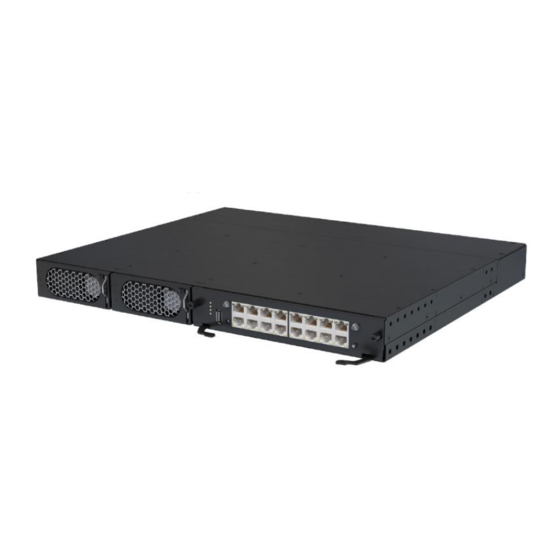
Page 24: Device Description
User Manual 3 Device Description Device Description 3.1 ECC800 The ECC800 consists of power supply units (PSUs) and an ECC800 main control module and monitors the equipment and environment in the smart module. Figure 3-1 ECC800 (front view) (1) PSU 1... - Page 25 ECC800 Data Center Controller User Manual 3 Device Description The ECC800 shown in the figure is fully configured with PSUs. PSUs 1 and 2 are optional depending on the application scenario. Figure 3-2 ECC800 (rear view) (1) 53.5 V DC_OUT1 (2) 53.5 V DC_OUT2...
- Page 26 5%–95% RH (non-condensing) Altitude 0–4000 m (When the altitude is between 3000 m and 4000 m, the temperature decreases by 1° C for each additional 200 m.) Table 3-2 ECC800 structural specifications Item Specifications Dimensions (L x W x H) 442 mm x 330 mm x 43.6 mm...
- Page 27 WCDMA BAND: 850 MHz–2100 MHz GSM: 850 MHz–1900 MHz 3G/4G E.I.R.P.Power 36 dBm (Max.) Driver version V100 Indicators Table 3-5 Indicators on the ECC800 main control module Indicator Color Name Status Description Green Running status Steady on The power supply is normal, the Issue 06 (2020-01-02) Copyright ©...
- Page 28 The power supply is abnormal. Blinking at long The software runs properly (the intervals indicator blinks at 0.5 Hz, on for 1s and then off for 1s) or the ECC800 registers with the NetEco successfully. Blinking at The ECC800 does not register with...
- Page 29 1s). Fault indicator Steady on The converter locks out due to output overvoltage. The converter delivers no output due to internal faults. The converter is working properly. Issue 06 (2020-01-02) Copyright © Huawei Technologies Co., Ltd.
- Page 30 None 3s. Then the IP address for the ECC800 WAN_1 port will restore to the default address 192.168.1.10. Communications Ports The ECC800 provides the following communications ports. Figure 3-4 shows the pins of the RJ45 port. Issue 06 (2020-01-02) Copyright © Huawei Technologies Co., Ltd.
- Page 31 RS485 port pin definitions. Table 3-9 RS485 port pin definitions Item Description Pin sequence Pin 1 RS485+ Pin 2 RS485– Pin 3 12 V DC_OUT Pin 4 RS485+ Pin 5 RS485– Issue 06 (2020-01-02) Copyright © Huawei Technologies Co., Ltd.
- Page 32 Off: No 12 V DC output is provided. There are two DO dry contact outputs (DO_1 and DO_2). Table 3-11 provides the DO port pin definitions. Table 3-11 DO port pin definitions Item Description Issue 06 (2020-01-02) Copyright © Huawei Technologies Co., Ltd.
- Page 33 Pin 2 Pin 3 Pin 4 Power Ports The ECC800 provides four power ports, including two AC input ports (AC_INPUT1 and AC_INPUT2) and two DC output ports (DC_OUTPUT1 and DC_OUTPUT2). Table 3-13 provides the power port pin definitions. Table 3-13 Power port pin definitions...
-
Page 34: Ecc800E
450 mA. NOTE The Pin 1, Pin 2, Pin 4, and Pin 5 in the COM4 port provide the RS485 signal. These four pins are shared with the COM3 port. Issue 06 (2020-01-02) Copyright © Huawei Technologies Co., Ltd. - Page 35 NetEco successfully. Blinking The ECC800e does not at short register with the NetEco (the intervals indicator blinks at 4 Hz, on for 0.125s and then off for 0.125s). Issue 06 (2020-01-02) Copyright © Huawei Technologies Co., Ltd.
-
Page 36: Southbound Device Introduction
(2) 48 V DC power input (3) PoE port (4) COM1/12V port port (5) COM2/12V (6) COM3 port (7) COM4 port (8) NTC1-3 port (9) NTC4-6 (10) AI/DI_1 port (11) AI/DI_2 port (12) 12V_1 port Issue 06 (2020-01-02) Copyright © Huawei Technologies Co., Ltd. - Page 37 There is no power input. indicator Green Module The power is abnormal or running the board program is loading. status indicator Blinking at The software runs properly long (the indicator blinks at 0.5 Issue 06 (2020-01-02) Copyright © Huawei Technologies Co., Ltd.
-
Page 38: Smart Eth Gateway
3.3.2 Smart ETH Gateway A smart ETH gateway allows the extension of the 53.5 V DC power supply and FE communication for the ECC800 and can be flexibly deployed in a smart module. Figure 3-7shows a smart ETH gateway. - Page 39 Blinking at The smart ETH gateway long successfully registers with intervals the ECC800 and the software runs properly (the indicator blinks at 0.5 Hz, on for 1s and then off for 1s). Blinking at The smart ETH gateway does...
-
Page 40: Access Actuator
The access actuator is the control component for the aisle door in a smart module. It connects to the ECC800 controller over FE port, wireless networking (802.15.4). It opens the magnetic lock by detecting the card swiping information of the card reader, door open button information, and fire linkage information. - Page 41 Table 3-22 Access actuator indicator description Indicato Color Name Status Description Green Power input Steady on The power input is normal. status indicator There is no power input. Issue 06 (2020-01-02) Copyright © Huawei Technologies Co., Ltd.
- Page 42 Blinking at The access actuator long intervals successfully registers with the ECC800 and the software runs properly (the indicator blinks at 0.5 Hz, on for 1s and then off for 1s). Blinking at The communication is...
-
Page 43: Ac Actuator
(disabled by default), or signals from the light button. It also provides a charging port for the pad. The AC actuator can connect to the ECC800 controller by wireless networking (802.15.4). - Page 44 (the indicator blinks at 0.5 Hz, on for 1s and then off for 1s). Blinking at The communication is short intervals disconnected or the AC actuator fails to register Issue 06 (2020-01-02) Copyright © Huawei Technologies Co., Ltd.
-
Page 45: Skylight Actuator
The skylight actuator supports E-labels and wireless networking (802.15.4). Figure 3-10 shows a skylight actuator. Issue 06 (2020-01-02) Copyright © Huawei Technologies Co., Ltd. - Page 46 One DI input port for connecting to the window open button BLINK button Hold down the button for less than 1 second to start blinking. Hold down the button for 1–5 seconds to search for a network and Issue 06 (2020-01-02) Copyright © Huawei Technologies Co., Ltd.
- Page 47 Blinking at The skylight actuator long intervals successfully registers with the ECC800 and the software runs properly (the indicator blinks at 0.5 Hz, on for 1s and then off for 1s). Blinking at The communication fails or...
-
Page 48: Multi-Functional Sensor
BUTTON/GND pin sequence BUTTON 3.3.6 Multi-Functional Sensor A multi-functional sensor integrates the temperature and humidity (T/H) sensor and smoke sensor. The multi-functional sensor can connect to the ECC800 over FE or wireless communication. Issue 06 (2020-01-02) Copyright © Huawei Technologies Co., Ltd. - Page 49 Hold down the button for 1–5 seconds to search for a network and start networking. Hold down the button for more than 6 seconds to clear network parameters. Smoke sensor test Supported button Issue 06 (2020-01-02) Copyright © Huawei Technologies Co., Ltd.
- Page 50 0.5 Hz, on for 1s and then off for 1s). Blinking at The multi-functional short intervals sensor fails to register with the ECC800 or the communication fails (the indicator blinks at 4 Hz, on for 0.125s and then off for 0.125s). Blinking...
-
Page 51: Water Sensor
(1) Conversion (2) Conversion cable end B, (3) Water detection cable end A, cable connected to the water detection connected to the conversion cable cable (4) Water (5) Communications/Power cable detection cable Issue 06 (2020-01-02) Copyright © Huawei Technologies Co., Ltd. -
Page 52: Wlds900 Water Sensor
(3) Conversion cable to the water detector (4) Conversion cable (5) Water detection cable end A, (6) Water detection end B, connected to connected to the conversion cable cable the water detection cable Issue 06 (2020-01-02) Copyright © Huawei Technologies Co., Ltd. -
Page 53: Electrode Water Sensor
–40° C to +80° C Operating temperature –40° C to +85° C Storage temperature Humidity 0–100% RH (non-condensing) Insulation resistance > 500 megohms Reliability test Failure rate: 800 fits Power consumption < 1 W Issue 06 (2020-01-02) Copyright © Huawei Technologies Co., Ltd. -
Page 54: Wifi Converter
One PoE port, complying with IEEE802.3at, 25.5 W Reset button Press and hold down the button for more than 5s to restore the factory settings of the WiFi converter. WPS button Support fast WiFi access by WPS Issue 06 (2020-01-02) Copyright © Huawei Technologies Co., Ltd. -
Page 55: Wifi Module
Blinking at The WiFi converter long intervals status successfully registers with the indicator ECC800 and the software runs properly (the indicator blinks at 0.5 Hz, on for 1s and then off for 1s). Blinking at The WiFi converter fails to... - Page 56 5.0 V DC± 5% Operating -20° C to +70° C temperature Storage -40° C to +90° C temperature Relative humidity 10%–90% RH (non-condensing) Storage humidity 5%–90% RH (non-condensing) Power < 0.8 W Issue 06 (2020-01-02) Copyright © Huawei Technologies Co., Ltd.
-
Page 57: Eth Converter
If you press the BLINK button, the RUN indicator blinks intermittently at button super short intervals (blinking at super short intervals for 0.5s and then off for 0.5s) for 10 seconds. Issue 06 (2020-01-02) Copyright © Huawei Technologies Co., Ltd. -
Page 58: Access Control Device
1s). Blinking at The communication fails or short the ETH converter fails to intervals register with the ECC800 (the indicator blinks at 4 Hz, on for 0.125s and then off for 0.125s). Blinking The indicator blinks at super short intervals for 0.5s... - Page 59 Operating mode Standby: The blue indicator is on, and the green indicator for the fingerprint reader is steady on. Fingerprint collection: The red indicator for the fingerprint reader is on. Issue 06 (2020-01-02) Copyright © Huawei Technologies Co., Ltd.
- Page 60 Rated voltage 12 V DC ± 5% Operating current Rated current 300 mA ± 5% Card type supported IC card Authorized storage A maximum of 1000 authorized users, with a maximum of 3000 fingerprints Issue 06 (2020-01-02) Copyright © Huawei Technologies Co., Ltd.
- Page 61 Table 3-41 Specifications for the card reader with a keypad Item Specifications Dimensions (L x W x H) 114 mm x 63 mm x 25 mm Operating voltage Operating voltage range: 10.8–13.2 V DC; rated voltage: 12 V DC Issue 06 (2020-01-02) Copyright © Huawei Technologies Co., Ltd.
-
Page 62: Pad
3.3.12 Pad The pad allows the wireless access from the data center management system. You can monitor the equipment in the data center and environmental parameters in real time over the APP. Issue 06 (2020-01-02) Copyright © Huawei Technologies Co., Ltd. - Page 63 Extension card: microSD, a maximum of 64 GB supported Button/Port Power switch and volume button 3.5 mm stereo headphones port Micro SD card port Micro-USB port that supports charging and synchronization Issue 06 (2020-01-02) Copyright © Huawei Technologies Co., Ltd.
-
Page 64: T/H Sensor
The BOM number for Polymer T/H sensors is 33010346. The BOM number for Ambient T/H sensors is 02310NBS. 3.3.13.1 T/H sensor (BOM number:33010346) Figure 3-23 Appearance The T/H sensor uses an RJ45 connector. Issue 06 (2020-01-02) Copyright © Huawei Technologies Co., Ltd. - Page 65 0%–100% RH ≤ ±5% RH (25°C, 30%–80% RH) Humidity accuracy Operating temperature -20° C to 70° C Operating voltage 9–16 V DC Storage temperature -40° C to 80° C (non-condensing) Output RS485 Issue 06 (2020-01-02) Copyright © Huawei Technologies Co., Ltd.
-
Page 66: T/Ht/H Sensor (Bom Number:02310Nbs)
RS485- Pin 4 RS485+ Pin 5 or Pin 6 Table 3-48 Temperature and humidity sensor specifications Item Specifications –20° C to +70° C Temperature measuring range Temperature accuracy ± 1° C Issue 06 (2020-01-02) Copyright © Huawei Technologies Co., Ltd. -
Page 67: Infrared Remote Control Module
Infrared emission distance Power supply 9–16 V DC ≤ 350 mA Power –10° C to +50° C Operating temperature Operating humidity 5%–95% RH Protection level IP20 Indicator Communication indicator and Run indicator Issue 06 (2020-01-02) Copyright © Huawei Technologies Co., Ltd. -
Page 68: Sms Module
SMS after an alarm is generated or eliminated. Sends an active alarm after the ECC800 powers off and restarts. − The SMS function of the 3G module in the ECC800 cannot coexist with the external SMS module connected to the USB port. 3.3.16 Smoke Detector Smoke detectors are used to detect the smoke concentration. -
Page 69: Temperature Sensor
Ambient humidity Dimensions Diameter: 112 mm, height: 41 mm 3.3.17 Temperature Sensor The temperature sensor (the code: 33010348) is used for the surface temperature measure, industrial process control, measurement instrument, etc. Issue 06 (2020-01-02) Copyright © Huawei Technologies Co., Ltd. -
Page 70: Alarm Beacon
Figure 3-30 shows an alarm beacon. Figure 3-30 Alarm beacon Table 3-53 lists the structural specifications of an alarm beacon. Issue 06 (2020-01-02) Copyright © Huawei Technologies Co., Ltd. -
Page 71: Intelligent Battery Monitoring System
In the scenario with battery cabinets, the CIM is installed inside a smart module battery cabinet and the CIM communications cable connects to a smart ETH gateway. Figure 3-31 shows the CIM and BIM networking in the scenario with battery cabinets. Issue 06 (2020-01-02) Copyright © Huawei Technologies Co., Ltd. -
Page 72: Cim
Accurately identifies weak batteries in a battery string. Identifies loose battery terminals and battery terminal overtemperature, and controls battery switch tripping. Supports WebUI display, northbound communication over FE and RS485, and a third-party NMS. Issue 06 (2020-01-02) Copyright © Huawei Technologies Co., Ltd. - Page 73 (7) RF_Z antenna port (8) BCB_1–BCB_4 (9) BCB_OUT and BCB_IN ports ports (10) Networking switch (11) PWR indicator (12) RUN indicator (13) ALM indicator (14) RF_Z indicator (15) Delivered antenna Issue 06 (2020-01-02) Copyright © Huawei Technologies Co., Ltd.
- Page 74 Figure 3-35 Power port pins Table 3-55 12 V, 2 A port pin definitions Definition Description – In this scenario, an external power module is adopted to supply 12 V DC operating voltage. Issue 06 (2020-01-02) Copyright © Huawei Technologies Co., Ltd.
- Page 75 Table 3-57 PoE port pin definitions Definition Description Supports power supply through the PoE port. The TX– terminal is an RJ45 terminal with an indicator. 4, 5 P45_P1 RX– 7, 8 P78_P1 Issue 06 (2020-01-02) Copyright © Huawei Technologies Co., Ltd.
- Page 76 Open: The dry Open Dry contact input signal contact input is input and – open. output signal Closed: The dry contact input is closed. Dry contract Open: The dry Open Issue 06 (2020-01-02) Copyright © Huawei Technologies Co., Ltd.
- Page 77 The value of Multi-Hall cur. setting equals the number of positive or negative Hall effect sensors in a single battery string and should be greater than or equal to 1. Issue 06 (2020-01-02) Copyright © Huawei Technologies Co., Ltd.
- Page 78 Grounded: Disconnected Receives whether whether the connected. the BCB cascaded commands connects BCBs sent by the Disconnec to the connect to UPS and ted: BCB signal the signal supports Issue 06 (2020-01-02) Copyright © Huawei Technologies Co., Ltd.
- Page 79 Secondary side ground tripping. 12 V: There is a driving signal for tripping. DIP Switch Table 3-63 DIP switch description Definition Description ADDR_1 RS485 communications address setting ADDR_2 ADDR_3 ADDR_4 Issue 06 (2020-01-02) Copyright © Huawei Technologies Co., Ltd.
- Page 80 If yes, minutes.) reconnect communic ation cable. If no, go to the next step. 2. Check whether the device is malfunctionin If yes, replace the device. If no, Issue 06 (2020-01-02) Copyright © Huawei Technologies Co., Ltd.
- Page 81 Button holding down Press and hold the Clears the current network (including button for more than the network parameters of all the online 10s but less than 20s. BIMs). Issue 06 (2020-01-02) Copyright © Huawei Technologies Co., Ltd.
-
Page 82: Bim
Table 3-67 Indicator description Indicator Color Silk Status Description Screen Running Green Power consumption is low or the BIM is not powered on. Blinking at The networking has started but not super short completed. Issue 06 (2020-01-02) Copyright © Huawei Technologies Co., Ltd. - Page 83 Initializes the network parameters if there is a network. Button holding Hold down the button Clears the current network and resets the down for more than 5 wireless module; disconnect the network. seconds. Issue 06 (2020-01-02) Copyright © Huawei Technologies Co., Ltd.
-
Page 84: Ui Description
Step 1 Connect a network cable between the PC network port and the WAN_1 port (protected by a security mechanism) on the ECC800. Table 4-1 lists the default IP addresses for the WAN and LAN ports on the ECC800. Table 4-1 Default IP addresses for the WAN and LAN ports on the ECC800 Port... - Page 85 Step 3.3 Step 3.4. If the ECC800 connects to the Internet, and the PC in a LAN accesses the Internet over a proxy server, do not perform Step 3.3 Step 3.4. Otherwise, you will fail to access the ECC800.
-
Page 86: Webui Description
An account is logged out due to timeout if no operation is performed within 10 minutes after system login. ----End 4.1.2 WebUI Description For data transmission security, the ECC800 supports WebUI access through SSL. This section uses the WebUI for the FusionModule500 system type as an example. Table 4-2 describes the... - Page 87 ECC800 Data Center Controller User Manual 4 UI Description Figure 4-2 WebUI menu hierarchy (FusionModule500) Issue 06 (2020-01-02) Copyright © Huawei Technologies Co., Ltd.
- Page 88 ECC800 Data Center Controller User Manual 4 UI Description Figure 4-3 WebUI menu hierarchy (FusionModule2000) Issue 06 (2020-01-02) Copyright © Huawei Technologies Co., Ltd.
- Page 89 ECC800 Data Center Controller User Manual 4 UI Description Figure 4-4 WebUI menu hierarchy (FusionModule1000) Figure 4-5 WebUI menu hierarchy (FusionModule800) Issue 06 (2020-01-02) Copyright © Huawei Technologies Co., Ltd.
-
Page 90: Common Operations And Settings
You have obtained the IP address of the ECC800 as well as the user name and password used for WebUI login. A PC with an IP address in the same network segment as that of the ECC800 is prepared, and the PC has connected to port WAN_1 on the ECC800. Context When you are setting key parameters for the monitoring system, the system will require second authentication. -
Page 91: How Can I View Version Information
Step 1 Log in to the ECC800 WebUI as an administrator. Step 2 Click in the upper right corner of the home page and view the ECC800 version information. Step 3 Choose Maintenance > Version Information and view the version information of ECC800 and connected device. -
Page 92: How To Restore Factory Settings
The value of Advance expiration notification (days) must not be greater than the value of Password validity period. The WebUI supports a maximum of 16 users and a maximum of five concurrent online users. ----End 4.1.3.3 How to Restore Factory Settings? Context Issue 06 (2020-01-02) Copyright © Huawei Technologies Co., Ltd. - Page 93 Parameters in System, Power Distribution, Aisle, Air Conditioner, and IT Cabinet under Monitoring will be restored to default values. For example, on the AI/DI_1–AI/DI_6 setting tab page (displayed after you choose System > ECC800 > Running Parameters), AI/DI_1 sensor-AI/DI_6 sensor will be restored to Disable. On the site device number tab page, Site device num will be restored to 0.
-
Page 94: App Introduction
You have obtained the IP address of the ECC800 as well as the user name and password used for WebUI login. A PC with an IP address in the same network segment as that of the ECC800 is prepared, and the PC has connected to port WAN_1 on the ECC800. Procedure Step 1 Download the app installation package using any of the following three methods: ... -
Page 95: Mobile Phone App
It is recommended that you use different user names to log in to both the ECC800 WebUI and app at the same time. If you use the same user name to log in to the WebUI and app at the same time, either of them will be forcibly logged out. - Page 96 IT equipment, smart cooling products, lights, and other devices) and PUE change curves. NOTE The Power screen is displayed only when Enable PUE function is set to Yes on the WebUI. Issue 06 (2020-01-02) Copyright © Huawei Technologies Co., Ltd.
-
Page 97: Pad App
Allows you to maintain the system. For example, you can import and export data, view network parameters, synchronize device parameters, and view the version information. 4.2.3 Pad APP Figure 4-10 Pad app menu hierarchy(FusionModule2000/FusionModule1000) Figure 4-11 Pad app menu hierarchy(FusionModule800) Issue 06 (2020-01-02) Copyright © Huawei Technologies Co., Ltd. - Page 98 Allows you to upgrade software. Allows you to maintain the system. For example, view the version information, import or export a configuration file, view network parameters, synchronize device parameters. Issue 06 (2020-01-02) Copyright © Huawei Technologies Co., Ltd.
-
Page 99: Power-On Commissioning
If the system type is not consistent with the type of the current micro-module, please choose the follows operates, in this example, the system type is changed to FusionModule1000A. Issue 06 (2020-01-02) Copyright © Huawei Technologies Co., Ltd. -
Page 100: Setting And Adding Devices
If you enter incorrect passwords for three consecutive times, you will be locked out for 5 minutes. Step 2 Tap to go to the Settings screen. Step 3 Choose Settings > Communication, and set IP address assign to Automatic(DHCP). Issue 06 (2020-01-02) Copyright © Huawei Technologies Co., Ltd. -
Page 101: Setting And Adding A Ups2000-G
User Manual 5 Power-On Commissioning Step 4 Tap to go back to the main menu screen. After setting parameters for the integrated UPS, connect the integrated UPS to the ECC800. ----End 5.3.2 Setting and Adding a UPS2000-G Procedure Step 1 Set monitoring parameters for the 3 kVA UPS2000-G. -
Page 102: Setting And Adding A Ups5000-E
The section describes how to add a UPS2000-G in a single UPS scenario. In a parallel UPS scenario, if the common communications address of the Modbus card is added to the ECC800, all UPS2000-Gs can be connected to the ECC800. - Page 103 Ensure that the baud rate of the UPS5000-E is consistent with that of the COM port on the ETH converter. Figure 5-3 UPS5000-E communication settings Step 2 Add a UPS5000-E. Log in to the ECC800 WebUI as an administrator. Add the UPS5000-E. Table 5-3 Adding a UPS5000-E Path...
-
Page 104: Adding And Setting A Sunrise-Scu-20K
ECC800 Data Center Controller User Manual 5 Power-On Commissioning Click Connect Test to check whether the UPS5000-E connects to the ECC800 properly. − If the UPS5000-E connects to the ECC800 properly, click Add Device. − If the UPS5000-E does not connect to the ECC800 properly, check whether the... -
Page 105: Setting Netcol5000-C030 Parameters (Over Modbus Tcp)
Choose Settings > Comm Settings > Modbus Settings, and set Connection mode to Server, Server encryption to Enable. After setting parameters for the NetCol5000-C030, the ECC800 discovers the access from the smart cooling product automatically. The earlier version has Protocol setting on the screen. The actual screen prevails. -
Page 106: Setting And Adding A Netcol5000-C030 (Over Modbus Rtu)
Table 5-5. The setting example indicates that the NetCol5000-C030 is connected to the COM1 port on the ECC800. If the NetCol5000-C030 is connected to another port, set the number of the connected port. Table 5-5 Adding NetCol5000-C030 parameters Parameter Name... -
Page 107: Setting The Netcol5000-A025 Or Netcol5000-A010 Parameters(Over Mac-Modbus)
User Manual 5 Power-On Commissioning − If the NetCol5000-C030 does not connect to the ECC800 properly, check whether the cable between the NetCol5000-C030 and the ECC800 is connected properly, whether the NetCol5000-C030 and ECC800 are running properly, and whether the input parameters are the consistent with the NetCol5000-C030 parameters. -
Page 108: Setting And Adding A Netcol5000-A035 (Over Modbus Rtu)
The NetCol5000-A035 connects to the smart ETH gateway through the ETH converter to communicate with the ECC800. The NetCol5000-A035 can also be directly connected to a COM port of the ECC800. After NetCol5000-A035 parameters are set, the ECC800 can automatically identify the access of the smart cooling product. -
Page 109: Setting And Adding A Pdu8000
ECC800. If the PDU8000 is connected to another port, set the number of the connected port. Ensure that the baud rate of the PDU8000 is consistent with that of the COM2 port on the ECC800. Ensure that the baud rate of the PDU8000 is consistent with that of the COM2 port on the ECC800. -
Page 110: Setting And Adding An Ats
Log in to the ECC800 WebUI as an administrator. Add an ATS. By default, an ATS is connected to port COM1 on the ECC800. If the ATS is connected to another port, set the COM port to the ECC800 port connected to the ATS. -
Page 111: Setting And Adding A Pdu2000-M(C)
− If the ATS device connects to the ECC800 properly, click Add Device. If the ATS device does not connect to the ECC800 properly, check whether the − cable between the ATS device and the ECC800 is connected properly, whether the ATS device and ECC800 are running properly, and whether the input parameters are the consistent with the ATS device parameters. - Page 112 Follow the instructions in the following table to add the PDU2000-M(C). The setting example indicates that the PDU2000-M(C) is connected to the COM1 port on the ECC800. If the PDU2000-M(C) is connected to another port, set the number of the connected port.
-
Page 113: Setting And Adding A Pmac625 Ac Meter
User Manual 5 Power-On Commissioning − If the PDU2000-M(C) does not connect to the ECC800 properly, check whether the cable between the PDU2000-M(C) and the ECC800 is connected properly, whether the PDU2000-M(C) and ECC800 are running properly, and whether the input parameters are consistent with the PDU2000-M(C) parameters. - Page 114 If the PMAC625 connects to the ECC800 properly, click Add Device. − If the PMAC625 does not connect to the ECC800 properly, check whether the cable between the PMAC625 and the ECC800 is connected properly, whether the PMAC625 and ECC800 are running properly, and whether the input parameters are consistent with the PMAC625 parameters.
-
Page 115: Setting And Adding A Pmac615 Ac Meter
Ensure that the baud rate of the PMAC615 (the default baud rate is 9600) is consistent with that of the COM3 port on the ECC800. Step 2 Add a PMAC615. Log in to the ECC800 WebUI as an administrator. Follow the instructions in the following table to add the PMAC615. Table 5-10 Adding a PMAC615... -
Page 116: Setting And Adding A Pdc Dc Meter
The communications address is 1 by default, and the baud rate is 9600 by default. Ensure that the baud rate of the DC meter is consistent with that of the COM2 port on the ECC800. Step 2 Add a PDC DC meter. -
Page 117: Adding An Ai/Di Sensor
If the PDC DC meter connects to the ECC800 properly, click Add Device. − If the PDC DC meter does not connect to the ECC800 properly, check whether the − cable between the PDC DC meter and the ECC800 is connected properly, whether the PDC DC meter and ECC800 are running properly, and whether the input parameters are consistent with the PDC DC meter parameters. -
Page 118: Setting And Adding An Independent Deployment Ai/Di Unit
WLDS600 water sensor based on the actual situation. Step 3 Click Connect Test to check whether the WLDS600 water sensor connects to the ECC800 properly. If the WLDS600 water sensor connects to the ECC800 properly, click Add Device. - Page 119 5-14. The setting example indicates that the independent deployment AI/DI unit is connected to the COM3 port on the ECC800. If the independent deployment AI/DI unit is connected to another port, enter the number of the connected port. ...
-
Page 120: Setting And Adding An Smart Cooling Product
Add the smart cooling product. The setting example indicates that the smart cooling product is connected to the COM1 port on the ECC800. If the smart cooling product is connected to another port, set the number of the connected port. -
Page 121: Setting And Adding A 48 V Dc Power Supply Device
Add the 48 V DC power supply device. The setting example indicates that the 48 V DC power supply device is connected to the COM3 port on the ECC800. If the device is connected to another port, set the number of the connected port. -
Page 122: Setting And Adding An Ac Or Dc Meter
Add the AC meter. The setting example indicates that the AC meter is connected to the COM2 port on the ECC800. If the AC meter is connected to another port, set the number of the connected port. Table 5-17 Setting parameters for the AC meter... -
Page 123: Setting And Adding A Hydrogen Detection System
If the AC meter connects to the ECC800 properly, click Add Device. − If the AC meter does not connect to the ECC800 properly, check whether the cable between the AC meter and the ECC800 is connected properly, whether the AC meter and ECC800 are running properly, and whether the input parameters are the consistent with the AC meter parameters. -
Page 124: Setting And Adding A Temperature And Humidity Sensor
If the hydrogen detection system connects to the ECC800 properly, click Add Device. − If the hydrogen detection system does not connect to the ECC800 properly, check whether the cable between the hydrogen detection system and the ECC800 is connected properly, whether the hydrogen detection system and ECC800 are running properly, and whether the input parameters are the consistent with the hydrogen detection system parameters. - Page 125 Add a T/H sensor. The setting example indicates that the T/H sensor is connected to the COM4 port on the ECC800. If the T/H sensor is connected to another port, set the number of the connected port. Table 5-21 Setting T/H sensor parameters...
-
Page 126: Adding A Networked Device
Networked devices, such as ATMs, are devices with IP attributes in an equipment room or site. By adding a networked device, you connect the device to the ECC800 in the same network so that the ECC800 monitors the device status. If the networked device is offline, the ECC800 will report a disconnection alarm on its WebUI. -
Page 127: Creating A Micro-Module Plan View
ECC800. The corresponding device icon in the WebUI plan view blinks. You can also drag a device on the ECC800 WebUI to report the blinking status to the device. Check that the device positions and types in the plan view are consistent with the actual situation by delivering the blinking command. -
Page 128: Checking Smart Module Plan Overview
Choose Home > Plan Overview > Page Configuration. Select 24 U cabinet or 42 U cabinet under Cabinet type. Click OK. Check the running information of ECC800, PDU, or UPS based on the requirements. Figure 5-11 Checking smart module configuration information ----End Issue 06 (2020-01-02) Copyright ©... -
Page 129: Creating A Container Plan View
You have obtained the IP address of the ECC800 as well as the user name and password used for WebUI login. A PC with an IP address in the same network segment as that of the ECC800 is prepared, and the PC has connected to port WAN_1 on the ECC800. ... -
Page 130: Setting Alarm Notification By Email And Sms
Prerequisites To implement alarm notification by SMS, the following conditions must be met: The ECC800 is configured with a 3G module into which a GSM or WCDMA SIM card is inserted. The SMS module is inserted into the USB port on the ECC800e and the SIM card is inserted into the SMS module. -
Page 131: Commissioning An Ac Actuator
To modify or delete the email parameter settings, click Modify or Delete button, the re-authentication page is displayed. Enter Login password and click Submit. 5.8 Commissioning an AC Actuator If an AC actuator is installed, perform the following steps to configure it. Issue 06 (2020-01-02) Copyright © Huawei Technologies Co., Ltd. - Page 132 The ECC800 exits the wireless networking (802.15.4) pairing status. If two or more ECC800 controllers need to be networked in wireless (802.15.4) mode, only one system can be networked at one time. During the networking, ensure that the RF_Z indicators on the ECC800 main control modules of other systems are blinking at long intervals or steady on.
-
Page 133: Commissioning Sensors
ALM indicator turns from the smoke compartment, and let off and the smoke sensor alarm smoke enter the smoke compartment disappears. through the hole in the side of the Issue 06 (2020-01-02) Copyright © Huawei Technologies Co., Ltd. - Page 134 (2) ALM indicator Step 3 (Optional) Set the audible and visual alarm linkage function for the multi-functional sensor as required. For the operation details, see 7.3 Linking Alarms with an Alarm Beacon. ----End Issue 06 (2020-01-02) Copyright © Huawei Technologies Co., Ltd.
-
Page 135: Commissioning A Smoke Sensor
The actual value prevails. Only the method of the parameter settings is described. Scenario 1: Connect the smoke sensor to the AI/DI port on the ECC800 (AI/DI_1 is used as an example). On the WebUI, choose Monitoring > System > ECC800 > Running Parameters >... - Page 136 The actual value prevails. Only the method of the parameter settings is described. Connect the WLDS900 water sensor to the AI/DI port on the ECC800 (AI/DI_4 is used as an example). On the WebUI, choose Monitoring > System > ECC800 > Running Parameters >...
-
Page 137: Commissioning A Temperature Sensor
The actual value prevails. Only the method of the parameter settings is described. Scenario 1: Connect the temperature sensor to the AI/DI port on the ECC800 (AI/DI_2 is used as an example). On the WebUI, choose Monitoring > System > ECC800 > Running Parameters >... -
Page 138: Commissioning A Door Status Sensor
WebUI. Scenario 2: If the Front door open or Rear door open alarm is enabled, Front door open or Rear door open Issue 06 (2020-01-02) Copyright © Huawei Technologies Co., Ltd. -
Page 139: Commissioning An Access Control Device And A Cabinet Electronic Lock
Access Right Management page. The added or modified user accounts and rights are saved only in the ECC800 main control module. The modified rights take effect in the access control device only after you click Synchronize Permission on the Access Right Management page. - Page 140 IT Cabinet1 > E–LOCK1. − Permission validity period: Set Start date, Expiration date, and Allow door open period. You do not have to set a validity period for the cabinet lock. Issue 06 (2020-01-02) Copyright © Huawei Technologies Co., Ltd.
- Page 141 If the access control system uses a Card and password reader, choose Monitoring > Aisle > Access Actuator Group > Access Actuator n on the ECC800 WebUI, click Issue 06 (2020-01-02) Copyright © Huawei Technologies Co., Ltd.
- Page 142 For method 2: After you choose Query > n > E-LOCK n, and click Controls to open Access Event on the WebUI, you can view the door remotely. the type of this access control event. ----End Issue 06 (2020-01-02) Copyright © Huawei Technologies Co., Ltd.
-
Page 143: Commissioning An Exit Button And An Emergency Button
If CIMs and battery interface modules (BIMs) are installed, perform the following steps to commission. Procedure Step 1 Log in to the ECC800 WebUI as an administrator. Step 2 Choose Monitoring > Power Distribution > CIM > Running Parameters. Step 3 Set CIM single battery qty., Batt installation time, Battery string capacity, Current source, and Battery string No. - Page 144 Press the CIM networking switch for 2 seconds. When the RF_Z indicator on the CIM turns from blinking green at super short intervals to blinking green at long intervals, the networking is complete. Issue 06 (2020-01-02) Copyright © Huawei Technologies Co., Ltd.
-
Page 145: Commissioning Cameras And A Vcn500 (Smart Eth Gateway Networking Scenario)
Table 5-36 IP address plan Device Internal IP address External IP address Camera Example: 192.168.248.50; range: Camera external IP 192.168.248.50–192.168.248.99 address VCN500 Example: 192.168.248.55; range: VCN500 external IP 192.168.248.50–192.168.248.99 address Issue 06 (2020-01-02) Copyright © Huawei Technologies Co., Ltd. -
Page 146: Configuring The Vcn500
To ensure the normal operating of the ECC800, avoid high data traffic, such as the concurrent display of dynamic monitoring of cameras and VCN500 video playback. To ensure the normal operating of the ECC800, you can view the videos from a maximum of two IPC6325-WD-VR cameras concurrently. 5.11.1 Configuring the VCN500 Prerequisites For details about the VCN500 hardware description and installation, see the "Quick Start"... -
Page 147: Commissioning Ipc6325 Cameras
Set NAT IP to VCN500 external IP address, which is the same as the external IP address mapped from the VCN500 internal IP address displayed on the ECC800. Configure the NTP synchronization. After setting The NTP clock source server to Yes, set the IP address of the NTP server. - Page 148 (Dynamic Host Configuration Protocol). In the network, the IPC6325 camera automatically obtains an IP address in the same IP address segment as the ECC800 after the ECC800 and IPC6325 are powered on. Therefore, you need to reset the IPC6325 camera IP address before commissioning an IPC6325 camera.
- Page 149 ECC800 Data Center Controller User Manual 5 Power-On Commissioning Set coding protocol to H.264. Figure 5-22 Setting primary stream parameters Issue 06 (2020-01-02) Copyright © Huawei Technologies Co., Ltd.
-
Page 150: Commissioning Ipc6321 Cameras
Enter the camera IP address (192.168.0.120 by default) in the address bar of the Internet Explorer and press Enter button. Enter the preset user name admin and the preset password HuaWei123, and click Log Issue 06 (2020-01-02) Copyright © Huawei Technologies Co., Ltd. -
Page 151: Adding A Camera On The Vcn500
The version number is subject to the Quick Start delivered with the VCN500. The description and link in this document are for reference only. Procedure Step 1 Install Client/Server (C/S) client. Issue 06 (2020-01-02) Copyright © Huawei Technologies Co., Ltd. -
Page 152: Setting And Viewing Videos On The Ecc800 Webui
----End 5.11.5 Setting and Viewing Videos on the ECC800 WebUI Context After adding a video link on the ECC800 WebUI, you can access the linked camera page on the WebUI. Procedure Step 1 Log in to the ECC800 WebUI as an administrator. -
Page 153: Commissioning Cameras And A Vcn500 (Lan Switch Networking Scenario)
The version number is subject to the Quick Start delivered with the VCN500. The description and link in this document are for reference only. Issue 06 (2020-01-02) Copyright © Huawei Technologies Co., Ltd. - Page 154 Set NAT IP to VCN500 external IP address, which is the same as the external IP address mapped from the VCN500 internal IP address displayed on the ECC800. Configure the NTP synchronization. After setting The NTP clock source server to Yes, set the IP address of the NTP server.
-
Page 155: Commissioning Ipc6325 Cameras
Enter the preset user name admin and the preset password HuaWei123, and click Log Step 2 Preview the site situation in real time and check the camera coverage through videos. Adjust the lens if necessary. Issue 06 (2020-01-02) Copyright © Huawei Technologies Co., Ltd. -
Page 156: Commissioning Ipc6321 Cameras
If multiple cameras are accessed, retain the connection of one camera and disconnect connections from other cameras. After commissioning the connected camera, commission other cameras in the same way. Issue 06 (2020-01-02) Copyright © Huawei Technologies Co., Ltd. -
Page 157: Adding A Camera On The Vcn500
Step 1 Install Client/Server (C/S) client. Obtain HW_IVS_Client.exe file from the CD-ROM delivered with the VCN50. You can also log in to http://support.huawei.com/enterprise/ and search Client Package.zip to download the corresponding version software. Double-click HW_IVS_Client.exe, adopt the default installation mode, and wait until the installation is complete. - Page 158 (Optional) Group the cameras and click Next after grouping. Click Finish to finish adding a camera. Step 3 Set recording parameters. For details, see Verifying Platform Recording or the documents delivered with the VCN500. ----End Issue 06 (2020-01-02) Copyright © Huawei Technologies Co., Ltd.
-
Page 159: Remote Management
When the smart module can be connected to the NetEco, perform the following steps to configure parameters. Procedure Step 1 Apply for a fixed IP address to the equipment room network administrator. Step 2 Set the IP address, subnet mask, and default gateway on the ECC800 WebUI. Table 6-1 IP parameters Path Parameter... -
Page 160: Creating An Ecc800 On The Neteco
Data Center Planning window to switch to the Uncreated Device Information window. Click in the Uncreated Device Information window to switch to the Add Device window. You can add an ECC800 device to the specified modular in the Add Device window. For detailed operations, see Figure 6-1. -
Page 161: Third-Party Nms Management (Over Snmp)
Status, Start Time, End Time, and Information in the displayed Progress window. During binding of the ECC800 for the first time, the screen will be locked indefinitely when the progress bar reaches 30%, and displays Loading device profile. Please try it later. The actual operation results prevail. - Page 162 SNMPv3 as an example. Procedure Step 1 Apply to the equipment room network administrator for a fixed IP address. Step 2 Set the IP address, subnet mask, and default gateway on the ECC800 WebUI. Table 6-4 IP parameters Path...
- Page 163 ECC800 Data Center Controller User Manual 6 Remote Management 11. Click Export in the Mib File pane, export the Mib file, and send to the development engineers of the NMS. ----End Issue 06 (2020-01-02) Copyright © Huawei Technologies Co., Ltd.
-
Page 164: Feature Description
7.1 PLC Function 7.1.1 PLC Introduction The ECC800 provides the flexible programmable logic controller (PLC) linkage function. You can set logic rules and control the DO output signal by collecting the signal value. You can select signals (such as the AI/DI device status signals) and perform logic operations such as AND, OR, NOT, GREATER THAN, LESS THAN, DELAY, and FILTER. -
Page 165: Plc Configuration Examples
The PLC linkage logic has been configured before delivery. You do not have to compile the logic program. Before adding or modifying PLC linkage logic, consult Huawei engineers. This section describes how to start a civil smart cooling product remotely and illustrates the configuration of the PLC logic program. - Page 166 User Manual 7 Feature Description Procedure Step 1 Log in to the ECC800 WebUI as an administrator. Step 2 Choose System Settings > PLC. Step 3 Ensure that Enable PLC Function is set to Yes. Step 4 (Optional) If Enable PLC Function is set to No, select Yes from the drop-down list box and click Submit.
-
Page 167: Linking Alarms With An Alarm Beacon
Follow-up Procedure You can use the configuration file import and export functions to export the PLC linkage rules configured for an ECC800 to a local PC and then import the rules to another ECC800. These functions achieve quick configuration. 7.2 Linking Alarms with an Alarm Beacon You can link alarms, namely the smoke alarm and AI/DI alarm, with the alarm beacon based on site requirements. -
Page 168: Fire Linkage
You have obtained the IP address of the ECC800 as well as the user name and password used for WebUI login. A PC with an IP address in the same network segment as that of the ECC800 is prepared, and the PC has connected to port WAN_1 on the ECC800. ... -
Page 169: Linking The Emergency Fan
7.4 Linking the Emergency Fan Prerequisites You have obtained the ECC800 IP address as well as the user name and password used for logging in to the WebUI. You have prepared a PC with an IP address in the same network segment as that of the ECC800, and the PC has connected to port WAN_1 on the ECC800. -
Page 170: Battery Shallow Discharge Test
7 Feature Description Procedure Step 1 Log in to the ECC800 WebUI as an administrator. Step 2 Choose System Settings > PLC. Step 3 Check that Enable PLC Function is Yes. If Enable PLC Function is No, choose Yes from the drop-down list box, and then click Submit. -
Page 171: Control Management Of The Infrared Remote Control Module
3. During a battery shallow discharge test, if the mains outage occurs, the backup capacity may be inconsistent with the rated capacity. Procedure Step 1 Log in to the ECC800 WebUI as an administrator. Step 2 Choose System Settings > PLC. Step 3 Set Enable PLC function to Yes and click Submit. -
Page 172: Setting And Adding An Infrared Remote Control Module
By default, an infrared remote control module is connected to port COM2 on the ECC800. If the infrared remote control module is connected to another port, set the COM port to the ECC800 port connected to the infrared remote control module. -
Page 173: Control Function Of An Infrared Remote Control Module
Click Connect Test to check whether the infrared remote control module connects to the ECC800 properly. If the infrared remote control module connects to the ECC800 properly, click Add Device. If the infrared remote control module does not connect to the ECC800 properly,... -
Page 174: Icooling Function
If you do not press on the button within 20s, the smart cooling product remote control will exit the learning mode due to a timeout. You can click Learning the startup instruction on the ECC800 WebUI and start the learning mode again. - Page 175 ECC800 are placed in the proper position in the plan view. There must be an smart cooling product host in the smart module, and the host is connected to the ECC800 properly. The teamwork control of smart cooling products is set. ...
-
Page 176: Pue Configuration Management
When L1/L2 is enabled, smart cooling products enter the iCooling teamwork control mode. When L1/L2 is enabled, the T/H threshold can only be set on the ECC800 WebUI. When L1/L2 is disabled, smart cooling products enter the intelligent teamwork control mode (teamwork controlof smart cooling products). -
Page 177: Configuring Pue Standard Mode
NOTE When the configuration mode is set to Standard, the ECC800 can automatically calculate the PUE of multiple devices connected in the N+1 and 2N scenarios. When the configuration mode is set to User-defined, the devices whose total power consumption... - Page 178 Step 5 Set the PUE configuration mode to Standard, and click Submit. Step 6 View the PUE. Choose Query > Performance Data and set Device to ECC800 from the drop-down list box. For other searching criteria such as Performance data, Statistical period, Start time, and End time, select the item based on requirements and click Query.
-
Page 179: Configuring Pue User-Defined Mode
Deletes a parameter setting for the total power consumption or IT power consumption. Procedure Step 1 Log in to the ECC800 WebUI as an administrator. Step 2 Choose System Settings > PUE Configuration. Step 3 Ensure that PUE function is set to Enable. - Page 180 Figure 7-6 IT cabinet power consumption configuration Under Total Power Consumption Configuration and IT Cabinet Power Consumption Configuration, click the edit icon on the right to modify the multiple for calculating indicators, as shown in Figure 7-7. Issue 06 (2020-01-02) Copyright © Huawei Technologies Co., Ltd.
- Page 181 IT load output) Performance data source: The ECC800 obtains total electricity energy of branches from the power distribution devices. Step 7 You can also view the PUE in the dashboard or curve on the home page.
-
Page 182: Maintenance
The cable connection is Secure loose cables. connection secure. The cable is not damaged. Replace damaged cables. Table 8-2 Routine maintenance for the main control module in the ECC800 Check Item Expected Result Troubleshooting Indicator The green indicator is steady If the indicator is off or any abnormal on or blinking. -
Page 183: Common Faults And Troubleshooting
8.2 Common Faults and Troubleshooting Table 8-4 Common faults and troubleshooting for PSUs Symptom Possible Cause Measure The PWR indicator (green) There is no AC input. Check whether the AC input Issue 06 (2020-01-02) Copyright © Huawei Technologies Co., Ltd. - Page 184 The RUN indicator (green) The main control module Register the main control is blinking at 4 Hz. module with the NetEco. does not register with the Issue 06 (2020-01-02) Copyright © Huawei Technologies Co., Ltd.
- Page 185 The RUN indicator is off. The contact between the Check whether the independent deployment independent deployment AI/DI unit and the ECC800 AI/DI unit is faulty and is abnormal, or the whether the cable independent deployment connection between the AI/DI unit is faulty.
-
Page 186: Component Replacement
Step 3 Remove cables, the WiFi module, and antennas from the ECC800 main control module. Step 4 Loosen the screws on both sides of the ECC800 main control module and pull the handles on both sides of the ECC800 main control module to remove the main control module. -
Page 187: Replacing A Psu
ECC800 main control module. Figure 8-2 Installing the Micro SD and SIM cards Step 7 Install the spare ECC800 main control module in the ECC800 subrack and screw the screws on both sides of the ECC800 main control module. Step 8 Connect the communications cables, WiFi module, and antennas to the ECC800 main control module. -
Page 188: Replacing Ecc800 Antennas
Tools: ESD wrist strap, ESD gloves Materials: Spare ECC800 antennas of the same model are available and functional. Procedure Step 1 Remove the 2.4G and 3G antenna cables connected to the ports on the ECC800, as shown in Figure 8-4. Issue 06 (2020-01-02) -
Page 189: Replacing A Sim Card And Micro Sd Card
Step 2 Loosen the screws on both sides of the ECC800 main control module. Step 3 Pull the handles on both sides of the ECC800 main control module, and to remove the main control module. - Page 190 ECC800 Data Center Controller User Manual 8 Maintenance Figure 8-5 Removing the ECC800 main control module Step 4 Remove the SIM card and micro SD card from the card slot. Figure 8-6 Removing a SIM card and a micro SD card For the ECC800e, you only need to remove the spare micro SD card into the card slot.
-
Page 191: Replacing The Sim Card Inside The Sms Module
Step 6 Install the ECC800 main control module in the card slot. Step 7 Tighten the screws on both sides of the ECC800 main control module. Step 8 Reconnect signal cables to the ECC800 main control module panel based on the recorded information. - Page 192 The interval between pulling out and inserting the SMS module should exceed 20s. If no SMS module is displayed or the status indicates that the SMS module is not present, pull out and insert the SMS module again. ----End Issue 06 (2020-01-02) Copyright © Huawei Technologies Co., Ltd.
-
Page 193: Faq
WebUI login. A PC with an IP address in the same network segment as that of the ECC800 is prepared, and the PC has connected to port WAN_1 on the ECC800. 9.1.1 How to Install a Network Security Certificate? Context ... -
Page 194: How Can I Install A Device Access Certificate
You have obtained a device access certificate and the certificate key and have copied the certificate and key file to the PC. A preset certificate is provided for the ECC800 and its connected devices. If a higher security level is required, replace the certificate both on the ECC800 and the devices. ... -
Page 195: How To Set Parameters For Alarm Enable, Severity, And Loudspeaker
Step 2 Click Monitoring, select the device to be viewed, and select Running Info to view the real-time data of the device. Step 3 Choose Home > Active Alarms to view the active alarms of the ECC800. Click Details in the Alarm Details area to view alarm details of devices. -
Page 196: How Can I View Performance Data
9.1.6 How Can I View Performance Data? Procedure Step 1 Log in to the ECC800 WebUI as an administrator. Step 2 Choose Query > Performance Data. Step 3 Set Device, Performance data, Statistical period, Start time, and End time, and click Query. -
Page 197: How Can I Export Or Import A Configuration File
----End 9.1.9 How Can I Export Fault Information? Procedure Step 1 Log in to the ECC800 WebUI as an administrator. Step 2 Choose Maintenance > Fault Information. Step 3 (Optional) Select Encryption password for export and enter an encryption password. -
Page 198: How Can I Synchronize Device Parameters
Source Device: device before replacement Target Device: device after replacement If communication between the ECC800 and the device is interrupted during parameter synchronization, the synchronization fails. Ensure that the ECC800 and the device communicate properly and synchronize parameters again. -
Page 199: How To Associate An Alarm With A Do Output
Step 5 Choose Device type or Device from Linkage Type. Step 6 (Optional) Select ECC800 from Linked Device if you select Device for the Linkage Type. Step 7 Set DO1 or DO2 to Yes and click OK. Select a DO not used by other functions. Otherwise, the association setting fails. -
Page 200: How To Handle Do Association Failure
You can use the APP software to view the smart module data center layout, active alarms, historical alarms, asset details, performance data, operation logs, system parameters, and version information. Procedure Step 1 Log in to the ECC800 mobile phone or pad app as an administrator. Issue 06 (2020-01-02) Copyright © Huawei Technologies Co., Ltd. -
Page 201: How Can I Export And Import Data
----End 9.2.2 How Can I Export and Import Data? Procedure Step 1 Log in to the ECC800 mobile phone or pad app as an administrator. Step 2 Export data. Choose More > System Maintenance > Export Data. Select Local or USB from the Select export location drop-down list box. -
Page 202: How Can I Handle App Login Failure
User Manual 9 FAQ Procedure Step 1 Log in to the ECC800 mobile phone or pad app as an administrator. Step 2 Choose More > System Maintenance > Parameter Sync. Step 3 Select the source device and target device. ... -
Page 203: A Installation Appendix
Management System Wiring Diagram (FusionModule800) If no smart ETH gateway is configured onsite, connect the third smart cooling product to the WAN_2 port on the ECC800. Issue 06 (2020-01-02) Copyright © Huawei Technologies Co., Ltd. - Page 204 A Installation Appendix Figure A-1 Cable connections to the management system See the wiring diagram delivered with the FusionModule500. Management System Wiring Diagram (FusionModule500) See the wiring diagram delivered with the FusionModule500. Issue 06 (2020-01-02) Copyright © Huawei Technologies Co., Ltd.
-
Page 205: B Devices Connected To The Ecc800
ECC800 Data Center Controller User Manual B Devices Connected to the ECC800 Devices Connected to the ECC800 The following table lists the devices managed on the ECC800 WebUI. Table B-1 Table A-1 Device list Device Model Software Version Remarks Smart ETH gateway... - Page 206 ECC800 Data Center Controller User Manual B Devices Connected to the ECC800 Device Model Software Version Remarks UPS2000-G(6-10K) UPS2000 Modbus-RTU V100R001C00SPC6 UPS2000-G(15-20K UPS2000 Modbus-RTU V100R001C10SPC8 Integrated UPS(2.0) UPS5000 Modbus-TCP V100R002C41SPC3 UPS5000-E UPS5000 Modbus-RTU V100R003C01SPC2 PDU8000 Integrated PDU PDU8000 Modbus-TCP V100R002C41SPC4...
- Page 207 ECC800 Data Center Controller User Manual B Devices Connected to the ECC800 Device Model Software Version Remarks PMAC615 AC PMAC615 Modbus-RTU meter PMAC625 AC PMAC625 Modbus-RTU meter Infrared remote UT-H884 Modbus-RTU control module Water sensor WLDS600 Modbus-RTU WLDS900 AI/DI Electrode type...
-
Page 208: C Acronyms And Abbreviations
C Acronyms and Abbreviations Acronyms and Abbreviations alternating current analog input application Battery Interface Module Communication Interface Module direct current digital input digital output energy control center equipment serial number Ethernet fast Ethernet Issue 06 (2020-01-02) Copyright © Huawei Technologies Co., Ltd. - Page 209 Power Distribution Unit Programmable Logic Controller Power Over Ethernet power supply unit power usage effectiveness Radio Frequency Relative Humidity Registered Jack Restriction of the use of certain Hazardous RoHs Substances Issue 06 (2020-01-02) Copyright © Huawei Technologies Co., Ltd.
- Page 210 C Acronyms and Abbreviations Secure Digital Subscriber Identity Module SSID Service Set Identifier Transport Layer Security Uninterruptible Power System Universal Serial Bus Video Cloud Node WiFi Wireless Fidelity WiFi Protected setup Issue 06 (2020-01-02) Copyright © Huawei Technologies Co., Ltd.
Need help?
Do you have a question about the ECC800 and is the answer not in the manual?
Questions and answers