Huawei ECC800 User Manual
Data center controller
Hide thumbs
Also See for ECC800:
- User manual (321 pages) ,
- User manual (210 pages) ,
- User manual (230 pages)
Table of Contents
Advertisement
Quick Links
See also:
User Manual
Advertisement
Table of Contents

Related Manuals for Huawei ECC800


Summary of Contents for Huawei ECC800
- Page 1 ECC800 Data Center Controller V100R001C40 User Manual Issue Date 2019-02-28 HUAWEI TECHNOLOGIES CO., LTD.
- Page 2 Notice The purchased products, services and features are stipulated by the contract made between Huawei and the customer. All or part of the products, services and features described in this document may not be within the purchase scope or the usage scope. Unless otherwise specified in the contract, all statements, information, and recommendations in this document are provided "AS IS"...
-
Page 3: About This Document
About This Document About This Document Purpose This document describes the ECC800 data center controller (including the ECC800e) in terms of features, devices, user interfaces (UIs), and power-on commissioning, as well as frequently asked questions (FAQ) and troubleshooting measures. This document describes all the functions of the ECC800. Certain functions are implemented by hardware such as the UPS and PDU, and may be unavailable if the hardware is not connected to the ECC800. - Page 4 This issue is used for first office application (FOA). Change points: Optimized the scenario-based commissioning description for certain components. Added some FAQ. Issue Draft A (2017-02-15) This issue is used for first application. Issue 02 (2019-02-28) Copyright © Huawei Technologies Co., Ltd.
-
Page 5: Table Of Contents
2 Overview ..........................3 2.1 Positioning ..................................... 3 2.2 Application Scenarios ................................4 2.2.1 ECC800 system network diagram (FusionModule5000) ....................4 2.2.2 ECC800 system network diagram (FusionModule2000) ....................4 2.2.3 ECC800 system network diagram (FusionModule1000) ....................5 2.2.4 ECC800 system network diagram (FusionModule800) ....................6 2.2.5 ECC800e system network diagram (FusionModule500) .................... - Page 6 5.3.8 Setting and Adding a NetCol5000-A035 (over Modbus RTU) ..................101 5.3.9 Setting and Adding a PDU8000 or integrated PDU (over Modbus-TCP) ..............102 5.3.10 Setting and Adding a PDU8000 (over Modbus-RTU) ....................102 5.3.11 Setting and Adding a PDU2000-M(C) ........................104 Issue 02 (2019-02-28) Copyright © Huawei Technologies Co., Ltd.
- Page 7 5.7.1 Commissioning a Multi-functional Sensor ........................125 5.7.2 Commissioning a Smoke Sensor ..........................127 5.7.2.1 Commissioning a Smoke Sensor (connected to the AI/DI port on the ECC800) ...........127 5.7.2.2 Commissioning a Smoke Sensor (Connected to the AI/DI port on the skylight actuator) ........128 5.7.3 Commissioning a Water Sensor ............................129...
- Page 8 6.1 NetEco Management ................................165 6.1.1 Connecting the Communications Cable ........................165 6.1.2 Setting NetEco Parameters............................165 6.1.3 Creating an ECC800 on the NetEco ..........................166 6.2 Third-party NMS Management (over SNMP) ........................167 6.2.1 Connecting the Communications Cable ........................167 6.2.2 Setting SNMP Management Parameters ........................168 7 Feature Description ......................
- Page 9 9.1.15 How to Associate an Alarm Severity with a DO Output? ..................206 9.1.16 How Can I Handle DO Association Failure? ......................206 9.1.17 What Do I Do If the ECC800 WebUI Display Language Changes from Chinese to English During Use? ..207 9.1.18 How Can I Rectify Camera Access Restriction? .......................207 9.1.19 How Should I Add the Devices Accessed Through a Smart ETH Gateway over Modbus-TCP to the ECC800...
-
Page 10: Safety Precautions
Ensure that the product is used in environments that meet its design specifications to avoid causing malfunctions or damaging components and voiding the warranty. Personnel who plan to install or maintain Huawei equipment must receive a thorough training, understand all necessary safety precautions, and be able to correctly perform all operations. - Page 11 Wear goggles and protective gloves when drilling holes. After drilling, clean up metal shavings immediately. Moving heavy objects − Be cautious to avoid injury when moving heavy objects. − Wear protective gloves when moving sharp objects. Issue 02 (2019-02-28) Copyright © Huawei Technologies Co., Ltd.
-
Page 12: Overview
Overview 2.1 Positioning The ECC800 is an intelligent data center environment and device management system which features flexible layout, easy maintenance, and high reliability. The ECC800 is the core component for the smart module local management. It adopts the PoE bus for expansion, and allows all intelligent monitoring devices to be flexibly laid out so that it can manage the devices in the smart module. -
Page 13: Application Scenarios
In the figure, RF_Z indicates wireless networking. RF_Z(1) devices can communicate with the ECC800 in wireless mode. The RF_Z(2) BIM and CIM communicate with each other in wireless mode. RF_Z(1) and RF_Z(2) devices use different protocols and are isolated from each other. -
Page 14: Ecc800 System Network Diagram (Fusionmodule1000)
In the figure, RF_Z indicates wireless networking. RF_Z(1) devices can communicate with the ECC800 in wireless mode. The RF_Z(2) BIM and CIM communicate with each other in wireless mode. RF_Z(1) and RF_Z(2) devices use different protocols and are isolated from each other. -
Page 15: Ecc800 System Network Diagram (Fusionmodule800)
In the figure, RF_Z indicates wireless networking. RF_Z(1) devices can communicate with the ECC800 in wireless mode. The RF_Z(2) BIM and CIM communicate with each other in wireless mode. RF_Z(1) and RF_Z(2) devices use different protocols and are isolated from each other. -
Page 16: Ecc800E System Network Diagram (Fusionmodule500)
ECC800 Data Center Controller User Manual 2 Overview Figure 2-6 ECC800 system network diagram (FusionModule800) In the figure, RF_Z indicates wireless networking. The RF_Z BIM and CIM communicate with each other in wireless mode. 2.2.5 ECC800e system network diagram (FusionModule500) The system network diagram uses FusionModule500 V100R001 as an example. -
Page 17: Features
Supports intelligent battery monitoring management, which allows monitoring of individual cell voltage and internal resistance for discovery of failed cells. − Supports interworking with the NetEco, supports the SNMP protocol, allowing centralized management in various scenarios. Issue 02 (2019-02-28) Copyright © Huawei Technologies Co., Ltd. -
Page 18: Device Description
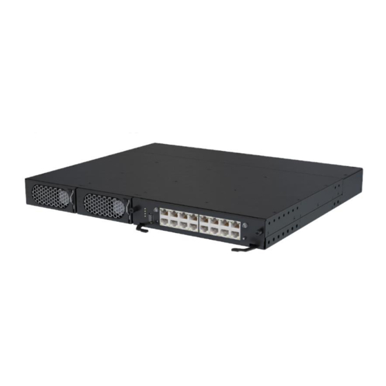
User Manual 3 Device Description Device Description 3.1 ECC800 The ECC800 consists of power supply units (PSUs) and an ECC800 main control module and monitors the equipment and environment in the smart module. Figure 3-1 ECC800 (front view) (1) PSU 1... - Page 19 ECC800 Data Center Controller User Manual 3 Device Description The ECC800 shown in the figure is fully configured with PSUs. PSUs 1 and 2 are optional depending on the application scenario. Figure 3-2 ECC800 (rear view) (1) 53.5 V DC_OUT1 (2) 53.5 V DC_OUT2...
- Page 20 Specifications Altitude 0–4000 m (When the altitude is between 3000 m and 4000 m, the temperature decreases by 1° C for each additional 200 m.) Table 3-2 ECC800 structural specifications Item Specifications Dimensions (L x W x H) 442 mm x 330 mm x 43.6 mm...
- Page 21 Button SW: wireless network pairing button Default: restores the default IP address Table 3-4 ECC800 RF parameters Model Name Specifications ECC800 RF_Z operation frequency 2405 MHz–2480 MHz RF_Z E.I.R.P.Power (Max.)
- Page 22 ECC800 Data Center Controller User Manual 3 Device Description Indicators Table 3-5 Indicators on the ECC800 main control module Indicator Color Name Status Description Green Running status Steady on The power supply is normal, indicator the program is being loaded, or WiFi WPS is pairing.
- Page 23 Power input overvoltage or undervoltage protection Reverse DC input connection Slight current imbalance Output overvoltage Hibernation The converter generates no protection alarms. Issue 02 (2019-02-28) Copyright © Huawei Technologies Co., Ltd.
- Page 24 30 minutes without pressing the button. Press and hold down the button for The RF_Z indicator more than 6s to clear network is on. parameters. Issue 02 (2019-02-28) Copyright © Huawei Technologies Co., Ltd.
- Page 25 ECC800 WAN_1 port will restore to the default address 192.168.1.10. Communications Ports The ECC800 provides the following communications ports. Figure 3-4 shows the pins of the RJ45 port. Figure 3-4 RJ45 port pins There are four FE ports, that is, two WAN ports (WAN_1 and WAN_2) and two LAN ports (LAN_1 and LAN_2).
- Page 26 There are six AI/DI dry contact inputs (AI/DI_1–6). Table 3-10 provides the AI/DI port pin definitions. Pins 1, 2, 4, and 5 identify sensor types. Pin 3 and Pin 8 are power output ports. Issue 02 (2019-02-28) Copyright © Huawei Technologies Co., Ltd.
- Page 27 DO_NO Pin 7 DO_COM Pin 8 Indicator Green Power output indicator indicator Steady on: The 12 V DC output is normal. Off: No 12 V DC output is provided. Issue 02 (2019-02-28) Copyright © Huawei Technologies Co., Ltd.
-
Page 28: Ecc800E
Pin 3 Pin 4 Power Ports The ECC800 provides four power ports, including two AC input ports (AC_INPUT1 and AC_INPUT2) and two DC output ports (DC_OUTPUT1 and DC_OUTPUT2). Table 3-13 provides the power port pin definitions. Table 3-13 Power port pin definitions... - Page 29 20 W, maximum withstand voltage of 60 V DC, and rated current of 0.5 A. Supports active DO port with the output voltage of 12 V DC and output current of 450 mA. Issue 02 (2019-02-28) Copyright © Huawei Technologies Co., Ltd.
- Page 30 A system failure alarm is generated. The system is normal. Green Power indicator Steady on The power supply for the system is normal. The power supply for the system is abnormal. Issue 02 (2019-02-28) Copyright © Huawei Technologies Co., Ltd.
-
Page 31: Southbound Device Introduction
(9) NTC4-6 (10) AI/DI_1 port (11) AI/DI_2 port (12) 12V_1 port (13) 12V_2 port (14) BLINK button (15) Status indicator Specifications Table 3-17 Technical specifications for the rack environment unit Item Specifications Issue 02 (2019-02-28) Copyright © Huawei Technologies Co., Ltd. - Page 32 Hz, on for 1s and then off for 1s). Blinking at PoE communication fails short (the indicator blinks at 4 Hz, intervals on for 0.125s and then off for 0.125s). Issue 02 (2019-02-28) Copyright © Huawei Technologies Co., Ltd.
-
Page 33: Smart Eth Gateway
3.3.2 Smart ETH Gateway A smart ETH gateway allows the extension of the 53.5 V DC power supply and FE communication for the ECC800 and can be flexibly deployed in a smart module. Figure 3-7 Smart ETH gateway (1) PWR_IN (2) FE_1 cascading (3) PoE_1–2 ports... - Page 34 Blinking at The smart ETH gateway long successfully registers with intervals the ECC800 and the software runs properly (the indicator blinks at 0.5 Hz, on for 1s and then off for 1s). Blinking at The smart ETH gateway does...
-
Page 35: General Input Unit
Specifications Power input PWR_IN power input terminal, for power cascading, input voltage range: 45–55 V DC. Power output PWR_OUT power output terminal, for power cascading, output voltage range: 45–55 V DC. Issue 02 (2019-02-28) Copyright © Huawei Technologies Co., Ltd. - Page 36 (blinking at 10 Hz, on for 0.05s and then off for 0.05s) for 0.5s, and then turns off for 0.5s. The cycle lasts for 10s. Alarm indicator Steady on A system failure alarm is generated. Issue 02 (2019-02-28) Copyright © Huawei Technologies Co., Ltd.
-
Page 37: Power Distribution Unit
Specifications Power input PWR_IN power input terminal, for power cascading, input voltage range: 45–55 V DC Power output PWR_OUT power output terminal, for power cascading, output voltage range: 45–55 V DC Issue 02 (2019-02-28) Copyright © Huawei Technologies Co., Ltd. - Page 38 Blinking at long The power distribution unit intervals has successfully registered with the ECC800 and the software runs properly (the indicator blinks at 0.5 Hz, on for 1s and then off for 1s). Blinking at The power distribution unit...
-
Page 39: Access Control System
The access actuator is the control component for the aisle door in a smart module. It connects to the ECC800 controller over FE port, wireless networking (802.15.4). It opens the magnetic lock by detecting the card swiping information of the card reader, door open button information, and fire linkage information. - Page 40 One DI input port for connecting to the door status switch RS485 serial Two RS485 ports (one route) with the default communications rate of port expansion 9600 bit/s, physical port cascading supported (reserved function) Issue 02 (2019-02-28) Copyright © Huawei Technologies Co., Ltd.
- Page 41 Indicators Table 3-27 Access actuator indicator description Indicator Color Name Status Green Power input status Steady on: The power indicator input is normal. Off: There is no power input. Issue 02 (2019-02-28) Copyright © Huawei Technologies Co., Ltd.
- Page 42 0.05s) and then turns off for 0.5s. The cycle lasts for 10s. Alarm indicator Steady on: A system failure alarm is generated. Off: No system alarm is generated. Issue 02 (2019-02-28) Copyright © Huawei Technologies Co., Ltd.
- Page 43 The access actuator provides one DO port (LOCK/GND) and one DI port (GATE/GND). Table 3-28 lists the LOCK/GND/GATE/GND port pin definitions. Table 3-28 LOCK/GND/GATE/GND port pin definitions Item Description LOCK/GND LOCK 12V_OUT (control magnetic locks) pin sequence GATE/GND GATE (door status) pin sequence Issue 02 (2019-02-28) Copyright © Huawei Technologies Co., Ltd.
-
Page 44: Fingerprint And Card Reader With A Keypad
Fingerprint reader The indicator blinks The indicator turns white twice and then on (white). turns on (red). Issue 02 (2019-02-28) Copyright © Huawei Technologies Co., Ltd. -
Page 45: Fingerprint And Card Reader
(2) LED indicator Table 3-31 Fingerprint and card reader Item Specifications Dimensions (L x W x H) 156 mm x 53 mm x 38 mm Rated operating voltage 12 V DC ± 5% Issue 02 (2019-02-28) Copyright © Huawei Technologies Co., Ltd. - Page 46 Card swiping LED indicator The indicator blinks The indicator blinks blue, red, and blue blue, red, and blue in order. in order. Buzzer sounds The buzzer sounds The buzzer sounds once. once. Issue 02 (2019-02-28) Copyright © Huawei Technologies Co., Ltd.
-
Page 47: Card Reader With A Keypad
12 V DC Operating current Static standby current 80 mA, dynamic operating current (card swiping, key pressing) 150 mA, minimum input current 12 V DC/300 mA Communications mode Wiegand communications port Issue 02 (2019-02-28) Copyright © Huawei Technologies Co., Ltd. -
Page 48: Magnetic Lock
Figure 3-16 Magnetic lock for a sliding door 3.3.5.2 Cabinet Access Control System The cabinet access control system applies to cabinets in the aisle containment to ensure data and device security. Issue 02 (2019-02-28) Copyright © Huawei Technologies Co., Ltd. - Page 49 The cabinet door can be opened with only the password and without the key. The user can set a password. A password should contain at least three digits. The password can be reset if the user forgot it. Issue 02 (2019-02-28) Copyright © Huawei Technologies Co., Ltd.
-
Page 50: Ac Actuator
The AC actuator is used in a smart module to control the lighting inside the smart module by receiving commands from the access control system or host, infrared linkage information (disabled by default), or signals from the light button. It also provides a charging port for the pad. Issue 02 (2019-02-28) Copyright © Huawei Technologies Co., Ltd. - Page 51 Press the button for less than 1 second to start blinking. Hold down the button for 1–5 seconds to search for a network and start networking. Hold down the button for more than 10 seconds to clear network parameters. Issue 02 (2019-02-28) Copyright © Huawei Technologies Co., Ltd.
- Page 52 Blinking at The AC actuator successfully long intervals registers with the ECC800 and the software runs properly (the indicator blinks at 0.5 Hz, on for 1s and then off for 1s). Blinking at The communication is...
-
Page 53: Skylight Actuator
Two AI/DI ports for detecting fire extinguishing linkage signals; smoke detection signals also supported DO output One 12 V DC power output for controlling the skylight magnetic lock; driving six skylight magnetic locks simultaneously Issue 02 (2019-02-28) Copyright © Huawei Technologies Co., Ltd. - Page 54 Blinking at The skylight actuator long intervals successfully registers with the ECC800 and the software runs properly (the indicator blinks at 0.5 Hz, on for 1s and then off for 1s). Blinking at The communication fails or the...
-
Page 55: Multi-Functional Sensor
D pin sequence 3.3.8 Multi-Functional Sensor A multi-functional sensor integrates the temperature and humidity (T/H) sensor and smoke sensor. The multi-functional sensor can connect to the ECC800 over FE or wireless communication. Issue 02 (2019-02-28) Copyright © Huawei Technologies Co., Ltd. - Page 56 Hold down the button for 1–5 seconds to search for a network and start networking. Hold down the button for more than 6s to clear network parameters. Smoke sensor Supported test button Issue 02 (2019-02-28) Copyright © Huawei Technologies Co., Ltd.
- Page 57 Blinking at The multi-functional sensor running status long successfully registers with indicator intervals the ECC800 and the software runs properly (the indicator blinks at 0.5 Hz, on for 1s and then off for 1s). Blinking at The multi-functional sensor short...
-
Page 58: Smoke Detector
< 95% RH (non-condensing) Dimensions Diameter: 112 mm, height: 41 mm 3.3.10 Temperature Sensor The temperature sensor (the code: 33010348) is used for the surface temperature measure, industrial process control, measurement instrument, etc. Issue 02 (2019-02-28) Copyright © Huawei Technologies Co., Ltd. -
Page 59: Alarm Beacon
Figure 3-24 Alarm beacon Table 3-44 Structural specifications of an alarm beacon Item Specifications Dimensions (L x W x H) 130 mm x 75 mm x 55 mm Issue 02 (2019-02-28) Copyright © Huawei Technologies Co., Ltd. -
Page 60: Water Sensor
A water sensor detects water on the floor in real time and generates an alarm when water is detected. 3.3.12.1 WLDS600 Water Sensor The WLDS600 water sensor with the BOM number of 33010465 consists of a water detection cable, a water detector, and a conversion cable. Issue 02 (2019-02-28) Copyright © Huawei Technologies Co., Ltd. -
Page 61: Wlds900 Water Sensor
Humidity 10%–80% RH (non-condensing) 3.3.12.2 WLDS900 Water Sensor The WLDS900 water sensor with the BOM number of 33010352 consists of a water detection cable, a water detector, and a conversion cable. Issue 02 (2019-02-28) Copyright © Huawei Technologies Co., Ltd. -
Page 62: Electrode Water Sensor
–40° C to +85° C Storage temperature Humidity 10%–80% RH (non-condensing) 3.3.12.3 Electrode Water Sensor The electrode water sensor with the BOM number of 33010444 contains electrode probes and cables. Issue 02 (2019-02-28) Copyright © Huawei Technologies Co., Ltd. -
Page 63: Wifi Converter
3.3.13 WiFi Converter The WiFi converter is used in a smart module to convert PoE signals into WiFi signals for communicating with devices such as the pad and mobile phone. Issue 02 (2019-02-28) Copyright © Huawei Technologies Co., Ltd. - Page 64 WPS function: If you choose Advanced settings > WPS connection on the WLAN of the intelligent device and press the WPS button on the WiFi converter at the same time, the intelligent device will quickly connect to the WiFi hotspot of the micro-module. Issue 02 (2019-02-28) Copyright © Huawei Technologies Co., Ltd.
-
Page 65: Wifi Module
Blinking at The WiFi converter status long intervals successfully registers with the indicator ECC800 and the software runs properly (the indicator blinks at 0.5 Hz, on for 1s and then off for 1s). Blinking at The WiFi converter fails to... -
Page 66: Eth Converter
5%–90% RH (non-condensing) Power < 0.8 W 3.3.15 ETH Converter The ETH converter is used to convert the Modbus–RTU protocol or CAN protocol to the Modbus-MAC protocol for connecting to the PoE bus. Issue 02 (2019-02-28) Copyright © Huawei Technologies Co., Ltd. - Page 67 (blinking at super short intervals for 0.5s and then off for 0.5s) for 10 seconds. E-label Supported Indicators Table 3-53 ETH converter indicators Indicator Color Name Status Description Issue 02 (2019-02-28) Copyright © Huawei Technologies Co., Ltd.
-
Page 68: Pad
1s). Blinking at The communication fails or short the ETH converter fails to intervals register with the ECC800 (the indicator blinks at 4 Hz, on for 0.125s and then off for 0.125s). Blinking The indicator blinks at super short intervals for 0.5s... - Page 69 Extension card: microSD, a maximum of 64 GB supported Button/Port Power switch and volume button 3.5 mm stereo headphones port Micro SD card port Micro-USB port that supports charging and synchronization with PC data Issue 02 (2019-02-28) Copyright © Huawei Technologies Co., Ltd.
-
Page 70: T/H Sensor
Operating system Android 4.4 (KitKat)+EMUI 3.0 3.3.17 T/H Sensor 3.3.17.1 T/H sensor (BOM number:33010346) Figure 3-32 Appearance The T/H sensor uses an RJ45 connector. Figure 3-33 Pins of an RJ45 connector Issue 02 (2019-02-28) Copyright © Huawei Technologies Co., Ltd. -
Page 71: T/H Sensor (Bom Number:02310Nbs)
3.3.17.2 T/H Sensor (BOM number:02310NBS) Figure 3-34 Appearance (1) Status indicator (2) RS485_IN (3) RS485_OUT (4) Address DIP switch The RS485 communications ports of the T/H sensor use RJ11 (6P6C) connectors. Issue 02 (2019-02-28) Copyright © Huawei Technologies Co., Ltd. - Page 72 –20° C to +70° C Temperature measuring range Temperature accuracy ± 1° C –10° C to +55° C Operating temperature Operating voltage 9–16 V DC –40° C to +70° C Storage temperature Output RS485 Issue 02 (2019-02-28) Copyright © Huawei Technologies Co., Ltd.
-
Page 73: Infrared Remote Control Module
Supports Modbus address setting 3.3.19 SMS Module Before using the SMS module, ensure that GSM/WCDMA signals must be available in the equipment room, and a SIM card needs to be prepared. Issue 02 (2019-02-28) Copyright © Huawei Technologies Co., Ltd. -
Page 74: Intelligent Battery Monitoring System
SMS after an alarm is generated or eliminated. − Sends an active alarm after the ECC800 powers off and restarts. The SMS function of the 3G module in the ECC800 cannot coexist with the external SMS module connected to the USB port. 3.3.20 Intelligent Battery Monitoring System The intelligent battery monitoring system consists of the CIM (CIM01C2) and BIM (BIM01C3). -
Page 75: Cim
An external Hall effect sensor is connected to monitor the current of each battery string. Calculates the SOC and SOH of batteries and battery strings. Accurately identifies weak batteries in a battery string. Issue 02 (2019-02-28) Copyright © Huawei Technologies Co., Ltd. - Page 76 (7) RF_Z antenna port (8) BCB_1–BCB_4 (9) BCB_OUT and BCB_IN ports ports (10) Networking switch (11) PWR indicator (12) RUN indicator (13) ALM indicator (14) RF_Z indicator (15) Delivered antenna Issue 02 (2019-02-28) Copyright © Huawei Technologies Co., Ltd.
- Page 77 Figure 3-41 Power port pins Table 3-62 12 V, 2 A port pin definitions Definition Description – In this scenario, an external power module is adopted to supply 12 V DC operating voltage. Issue 02 (2019-02-28) Copyright © Huawei Technologies Co., Ltd.
- Page 78 Table 3-64 PoE port pin definitions Definition Description Supports power supply through the PoE port. The TX– terminal is an RJ45 terminal with an indicator. 4, 5 P45_P1 RX– 7, 8 P78_P1 Issue 02 (2019-02-28) Copyright © Huawei Technologies Co., Ltd.
- Page 79 Open: The dry Open Dry contact input signal contact input is input and – open. output signal Closed: The dry contact input is closed. Dry contract Open: The dry Open Issue 02 (2019-02-28) Copyright © Huawei Technologies Co., Ltd.
- Page 80 The value of Multi-Hall cur. setting equals the number of positive or negative Hall effect sensors in a single battery string and should be greater than or equal to 1. Issue 02 (2019-02-28) Copyright © Huawei Technologies Co., Ltd.
- Page 81 BCB tripping. Secondary side ground Table 3-69 BCB_IN and BCB_OUT cascading port pin definitions Defini BCB_IN BCB_OUT Status Initial Description tion Signal Signal Description Status Descripti Descriptio Issue 02 (2019-02-28) Copyright © Huawei Technologies Co., Ltd.
- Page 82 Secondary side ground tripping. 12 V: There is a driving signal for tripping. DIP Switch Table 3-70 DIP switch description Definition Description ADDR_1 RS485 communications address setting ADDR_2 ADDR_3 ADDR_4 Issue 02 (2019-02-28) Copyright © Huawei Technologies Co., Ltd.
- Page 83 Green Northbound Blinking Requires no communication at long communication handling. status intervals is normal. Blinking Blinking, lasting Requires no intermitt for 10s. handling. ently at super short intervals Issue 02 (2019-02-28) Copyright © Huawei Technologies Co., Ltd.
- Page 84 If an indicator blinks at short intervals, it is blinking at 4 Hz, that is, on for 0.125s and then off for 0.125s. If an indicator blinks at super short intervals, it is blinking at 10 Hz, that is, on for 0.05s and then off for 0.05s. Issue 02 (2019-02-28) Copyright © Huawei Technologies Co., Ltd.
-
Page 85: Bim
Monitors the voltages, internal resistances, and pole temperatures of 12 V batteries. Supports the hibernation function. (When it detects that the battery voltage is low, it will enter the low-power mode.) Communicates with the CIM wirelessly. Issue 02 (2019-02-28) Copyright © Huawei Technologies Co., Ltd. - Page 86 If an indicator blinks at long intervals, it is blinking on for 1s and then off for 1s. If an indicator blinks at super short intervals, it is blinking at 10 Hz, that is, on for 0.05s and then off for 0.05s. Issue 02 (2019-02-28) Copyright © Huawei Technologies Co., Ltd.
- Page 87 Initializes the network parameters if there is a network. Button holding Hold down the button Clears the current network and resets the down for more than 5 wireless module; disconnect the network. seconds. Issue 02 (2019-02-28) Copyright © Huawei Technologies Co., Ltd.
-
Page 88: Ui Description
Step 1 Connect a network cable between the PC network port and the WAN_1 port (protected by a security mechanism) on the ECC800. Table 4-1 Default IP addresses for the WAN and LAN ports on the ECC800 Port Default IP Address WAN_1 192.168.1.10... - Page 89 Step 3.3 Step 3.4. If the ECC800 connects to the Internet, and the PC in a LAN accesses the Internet over a proxy server, do not perform Step 3.3 Step 3.4. Otherwise, you will fail to access the ECC800.
- Page 90 Then set the security level of the trusted site to the lowest. When switching between different versions of the ECC800 on your PC, you are advised to clear the historical Internet Explorer cache. Failing to do so may cause some information missed or exception after login.
-
Page 91: Webui
It is recommended that a maximum of three users log in to the ECC WebUI at the same time. ----End 4.1.2 WebUI For data transmission security, the ECC800 supports WebUI access through TLS. Figure 4-3 Home page Issue 02 (2019-02-28) - Page 92 View and manage the layout view of devices. View the system PUE in a dashboard and the system trend curve. Active Alarms Query active alarms. Multi-Module View the status of each cascaded ECC800. Monitoring Figure 4-4 WebUI menu hierarchy The actual menu hierarchy prevails. ...
-
Page 93: App Introduction
Set PUE parameters. Configure multi-module settings to cascade up to three ECC800s. Maintenance Upgrade the software of the ECC800 and southbound devices and download the app. Query the version and e-labels. Query and export fault information. - Page 94 Procedure Step 1 Connecting to a WiFi network. Method 1: Insert a WiFi module into the USB port on the ECC800. Figure 4-5 Installing a WiFi module Method 2: Connect cables between the WiFi converter and a smart ETH gateway as well as between the smart ETH gateway and the ECC800.
-
Page 95: Preparations And App Login
You have obtained the IP address of the ECC800 as well as the user name and password used for WebUI login. A PC with an IP address in the same network segment as that of the ECC800 is prepared, and the PC has connected to port WAN_1 on the ECC800. Procedure Step 1 Download and obtain the app installation package using any of the following three methods: ... - Page 96 It is recommended that you use different user names to log in to both the ECC800 WebUI and app at the same time. If you use the same user name to log in to the WebUI and app at the same time, either of them will be forcibly logged out.
-
Page 97: Mobile Phone App
Table 4-4 Mobile phone app functions Screen Function Home View the device layout diagram, and tap a device icon in the layout diagram to view the information configured for the device. Issue 02 (2019-02-28) Copyright © Huawei Technologies Co., Ltd. -
Page 98: Pad App
Upgrade software. Maintain the system. For example, import and export data, view network parameters, synchronize device parameters, and view the version information. Log out. 4.2.4 Pad App Figure 4-9 Home Issue 02 (2019-02-28) Copyright © Huawei Technologies Co., Ltd. - Page 99 View operation logs. Upgrade software. Maintain the system. For example, view the version information, import or export a configuration file, view network parameters, synchronize device parameters, and log out. Issue 02 (2019-02-28) Copyright © Huawei Technologies Co., Ltd.
-
Page 100: Power-On Commissioning
You have obtained the ECC800 IP address as well as the user name and password used for WebUI login. A PC with an IP address in the same network segment as the ECC800 IP address is prepared, and the PC has connected to the WAN_1 port on the ECC800. Context After installing or replacing the device or ECC800, set monitoring parameters and add the device. -
Page 101: Checking The System Type And Setting The Smart Module Name
Log in to the WebUI again to check that the system type has been changed. Step 2 Choose System Settings > Smart Module Settings, modify Smart module name, and click Submit in the Site ID area. Issue 02 (2019-02-28) Copyright © Huawei Technologies Co., Ltd. -
Page 102: Setting And Adding Devices
Step 3 Choose Settings > Communication, and set IP address assign to Automatic(DHCP). Step 4 Tap to go back to the main menu screen. After setting parameters for the integrated UPS, the ECC800 discovers the access from the integrated UPS automatically. ----End 5.3.2 Setting and Adding a UPS2000-G... - Page 103 Select COM2 from the drop-down list box. port NOTE The setting example indicates that the UPS2000-G is connected to the COM2 port on the ECC800. If the UPS2000-G is connected to another port, enter the number of the connected port. Issue 02 (2019-02-28)
-
Page 104: Setting And Adding A Ups5000-E
The section describes how to add a UPS2000-G in a single UPS scenario. In a parallel UPS scenario, if the common communications address of the Modbus card is added to the ECC800, all UPS2000-Gs can be connected to the ECC800. - Page 105 In this example, Device address is set to 1. During actual configuration, set the device address for the UPS5000-E based on the actual situation. Click Connect Test to check whether the UPS5000-E connects to the ECC800 properly. − If the UPS5000-E connects to the ECC800 properly, click Add Device.
-
Page 106: Adding And Setting A Sunrise-Scu-20K
In this example, Device address is set to 1. During actual configuration, set the device address based on the actual situation. Click Connect Test to check whether the SUNRISE-SCU-20K connects to the ECC800 properly. − If the SUNRISE-SCU-20K connects to the ECC800 properly, click Add Device. -
Page 107: Setting Netcol5000-C030 Parameters (Over Modbus Tcp)
Choose Settings > Comm Settings > Modbus Settings, and set Connection mode to Server, Server encryption to Enable. After setting parameters for the NetCol5000-C030, the ECC800 discovers the access from the smart cooling product automatically. The earlier version has Protocol setting on the screen. The actual screen prevails. -
Page 108: Setting And Adding A Netcol5000-C030 (Over Modbus Rtu)
In this example, Device address is set to 1. During actual configuration, set the device address for the NetCol5000-C030 based on the actual situation. Click Connect Test to check whether the NetCol5000-C030 connects to the ECC800 properly. − If the NetCol5000-C030 connects to the ECC800 properly, click Add Device. -
Page 109: Setting The Netcol5000-A025 Or Netcol5000-A010 Parameters(Over Mac-Modbus)
ECC800 Data Center Controller User Manual 5 Power-On Commissioning whether the NetCol5000-C030 and ECC800 are running properly, and whether the input parameters are consistent with the NetCol5000-C030 parameters. Step 3 Set the running parameters and control parameters for the NetCol5000-C030 on the WebUI. -
Page 110: Setting And Adding A Netcol5000-A035 (Over Modbus Rtu)
Comm address based on site requirements. The earlier version has Protocol setting on the screen. The actual screen prevails. Step 2 Set the running parameters and control parameters for the NetCol5000-A035 on the ECC800 WebUI. The NetCol5000-A035 connects to the smart ETH gateway through the ETH converter to communicate with the ECC800. -
Page 111: Setting And Adding A Pdu8000 Or Integrated Pdu (Over Modbus-Tcp)
PoE port on the smart ETH gateway. Context The method of connecting the PDU8000 to the ECC800 is the same as that for the integrated PDU. Connecting the integrated PDU to the ECC800 by following the instructions in this section. - Page 112 If the PDU8000 connects to the ECC800 properly, click Add Device. − If the PDU8000 does not connect to the ECC800 properly, check whether the cable between the PDU8000 and the ECC800 is connected properly, whether the PDU8000 and ECC800 are running properly, and whether the input parameters are consistent with the PDU8000 parameters.
-
Page 113: Setting And Adding A Pdu2000-M(C)
If you do not press MENU, the PDU2000-M(C) buzzes and restarts automatically after 30s and the setting parameters are not saved. Step 2 Add a PDU2000-M(C). Log in to the ECC800 WebUI as an administrator. Add a PDU2000-M(C). Table 5-8 Adding a PDU2000-M(C) -
Page 114: Setting Parameters For The Smart Busway
If the smart busway is used, general input units and power distribution units communicate with the ECC800 using the MAC-Modbus protocol. After the general input units and power distribution units properly connect to the ECC800, the ECC800 automatically identifies the units. - Page 115 Path: Maintenance > Parameter Sync Step 2 Set parameters for power distribution units on the ECC800 WebUI. (Optional) To modify the branch signal name of the power distribution unit, choose Monitoring > Power Distribution > Power Distribution Unit 1 > Running Parameters >...
-
Page 116: Setting And Adding An Ats
Choose Maintenance > Parameter Sync. ----End 5.3.13 Setting and Adding an ATS Prerequisites An ATS (automatic transfer switch) has connected to the COM port on the ECC800. Context After replacing an ATS or an ECC800, add an ATS on the ECC800 WebUI. Procedure Step 1 Set the ATS device address. -
Page 117: Setting And Adding A Pmac625 Ac Meter
If the ATS connects to the ECC800 properly, click Add Device. − If the ATS does not connect to the ECC800 properly, check whether the cable between the ATS and the ECC800 is connected properly, whether the ATS and ECC800 are running properly, and whether the input parameters are consistent with the ATS parameters. - Page 118 , modify the communications address value (ranging from 1 to 247) by pressing , and then press to save the setting. Figure 5-7 Communications address of the PMAC625 Step 2 Add a PMAC625. Log in to the ECC800 WebUI as an administrator. Add a PMAC625. Table 5-12 Adding a PMAC625 Path Parameter...
-
Page 119: Setting And Adding A Pmac615 Ac Meter
If the PMAC625 connects to the ECC800 properly, click Add Device. − If the PMAC625 does not connect to the ECC800 properly, check whether the cable between the PMAC625 and the ECC800 is connected properly, whether the PMAC625 and ECC800 are running properly, and whether the input parameters are consistent with the PMAC625 parameters. -
Page 120: Setting And Adding A Pdc Dc Meter
If the PMAC615 connects to the ECC800 properly, click Add Device. − If the PMAC615 does not connect to the ECC800 properly, check whether the cable between the PMAC615 and the ECC800 is connected properly, whether the PMAC615 and ECC800 are running properly, and whether the input parameters are consistent with the PMAC615 parameters. -
Page 121: Setting And Adding An Independent Deployment Ai/Di Unit
If the PDC DC meter connects to the ECC800 properly, click Add Device. − If the PDC DC meter does not connect to the ECC800 properly, check whether the cable between the PDC DC meter and the ECC800 is connected properly, whether the PDC DC meter and ECC800 are running properly, and whether the input parameters are consistent with the PDC DC meter parameters. - Page 122 The setting example indicates that the independent deployment AI/DI unit is connected to the COM3 port on the ECC800. If the independent deployment AI/DI unit is connected to another port, set the COM port to the ECC800 port connected to the independent deployment AI/DI unit. Device In this example, Device address is set to 1.
-
Page 123: Setting And Adding An Smart Cooling Product
----End 5.3.18 Setting and Adding an Smart Cooling Product Context In this example, the smart cooling product is connected to the COM1 port on the ECC800. Procedure Step 1 Set monitoring parameters for the smart cooling product. Set the communications address on the controller screen of the smart cooling product. -
Page 124: Setting And Adding A 48 V Dc Power Supply Device
In this example, set Device address to 1. Set the actual device address of the smart cooling product during operations. Click Connect Test to check whether the smart cooling product connects to the ECC800 properly. − If the smart cooling product connects to the ECC800 properly, click Add Device. -
Page 125: Setting And Adding An Ac Or Dc Meter
This section describes how to set and add an AC meter, and provides a reference for how to set and add a DC meter. In this example, the AC meter is connected to the COM2 port on the ECC800. Issue 02 (2019-02-28) -
Page 126: Setting And Adding A Hydrogen Detection System
If the AC meter connects to the ECC800 properly, click Add Device. − If the AC meter does not connect to the ECC800 properly, check whether the cable between the AC meter and the ECC800 is connected properly, whether the AC meter and ECC800 are running properly, and whether the input parameters are the consistent with the AC meter parameters. - Page 127 If the hydrogen detection system connects to the ECC800 properly, click Add Device. − If the hydrogen detection system does not connect to the ECC800 properly, check whether the cable between the hydrogen detection system and the ECC800 is connected properly, whether the hydrogen detection system and ECC800 are running properly, and whether the input parameters are the consistent with the hydrogen detection system parameters.
-
Page 128: Adding A Networked Device
Networked devices, such as ATMs, are devices with IP attributes in an equipment room or site. By adding a networked device, you connect the device to the ECC800 in the same network so that the ECC800 monitors the device status. If the networked device is offline, the ECC800 will report a disconnection alarm on its WebUI. -
Page 129: Creating A Smart Module Plan View
Hold down the BLINK button on a device for less than 1s to report the blinking status to the ECC800. The corresponding device icon in the WebUI plan view blinks. Drag a device in the WebUI plan view. The RUN indicator on the corresponding device blinks intermittently at super short intervals. - Page 130 Step 3 Hold down the BLINK button on a device such as a smart ETH gateway for less than 1s to report the blinking status to the ECC800. The corresponding device icon in the WebUI plan view blinks. Check that the device positions and types in the plan view are consistent with the actual situation by delivering the blinking command.
-
Page 131: Setting Alarm Notification By Email And Sms
Prerequisites To implement alarm notification by SMS, the following conditions must be met: The ECC800 is configured with a 3G module into which a GSM or WCDMA SIM card is inserted. The SMS module is inserted into the USB port on the ECC800e and the SIM card is inserted into the SMS module. -
Page 132: Commissioning The Ac Actuator (Wireless Networking)
That is, the RF_Z indicators on the ECC800 and AC actuator are both steady green. If the RF_Z indicator on the ECC800 is not steady green, hold down the SW button on the ECC800 for more than 6 seconds to make the ECC800 enter non-networking status. ... - Page 133 The ECC800 exits the wireless networking (802.15.4) pairing status. If two or more ECC800 controllers need to be networked in wireless (802.15.4) mode, only one system can be networked at one time. During the networking, ensure that the RF_Z indicators on the ECC800 main control modules of other systems are blinking at long intervals or steady on.
-
Page 134: Commissioning Sensors
Table 5-24 Function commissioning Check Method Normal Connection Status Temperature and humidity You can view the current ambient temperature and detection: View the running humidity. information about the multi-functional sensor on the WebUI. Issue 02 (2019-02-28) Copyright © Huawei Technologies Co., Ltd. - Page 135 After the commissioning is complete, clean up dust. Issue 02 (2019-02-28) Copyright © Huawei Technologies Co., Ltd.
-
Page 136: Commissioning A Smoke Sensor
Procedure Step 1 Set smoke sensor parameters. In this example, the smoke sensor is connected to the AI/DI_1 port on the ECC800. Log in to the ECC800 WebUI as an administrator. Choose Monitoring > System > ECC800 > Running Parameters > AI/DI_1 Port Settings. -
Page 137: Commissioning A Smoke Sensor (Connected To The Ai/Di Port On The Skylight Actuator)
The smoke sensor is connected to the AI/DI_1 on the FusionModule800 and AI/DI_1 sensor type needs to be set to NO because of the cables configuration and that the ECC800 cannot identify the sensor type. Step 2 Check the monitoring functions of smoke sensor. -
Page 138: Commissioning A Water Sensor
Step 1 Set water sensor parameters. In this example, the water sensor is connected to the AI/DI_4 port on the ECC800. The default alarm severity of the AI/DI port is Minor. If you want to change the alarm severity, see 9.1.7 How to Set Parameters for Alarm Enable, Severity, and Loudspeaker?. - Page 139 User Manual 5 Power-On Commissioning Step 2 Add a water sensor. In this example, the water sensor is connected to the COM1 port on the ECC800. Log in to the ECC800 WebUI as an administrator. Add a water sensor. Table 5-28 Adding a water sensor...
-
Page 140: Commissioning A Electrode Water Sensor
Procedure Step 1 Set water sensor parameters. In this example, the water sensor is connected to the AI/DI_3 port on the ECC800. Log in to the ECC800 WebUI as an administrator. Choose Monitoring > System > ECC800 > Running Parameters > AI/DI_3 Port Settings. -
Page 141: Commissioning A Temperature Sensor (Connected To The Ntc Port On The Rack Environment Unit)
User Manual 5 Power-On Commissioning In this example, the temperature sensor is connected to the AI/DI_2 port on the ECC800. Log in to the ECC800 WebUI as an administrator. Choose Monitoring > System > ECC800 > Running Parameters > AI/DI_2 Port Settings. - Page 142 If the T/H sensor connects to the ECC800 properly, click Add Device. − If the T/H sensor does not connect to the ECC800 properly, check whether the cable between the T/H sensor and the ECC800 is connected properly, whether the T/H sensor and ECC800 are running properly, and whether the input parameters are consistent with the T/H sensor parameters.
-
Page 143: Commissioning A T/H Sensor (Bom Number:02310Nbs)
Switch 1 Switch 2 Switch 3 Switch 4 Switch 5 Switch 6 Step 2 Add a T/H sensor. Log in to the ECC800 WebUI as an administrator. Add a T/H sensor. Table 5-36 Adding a T/H sensor Path Parameter Setting Name... - Page 144 If the T/H sensor connects to the ECC800 properly, click Add Device. − If the T/H sensor does not connect to the ECC800 properly, check whether the cable between the T/H sensor and the ECC800 is connected properly, whether the T/H sensor and ECC800 are running properly, and whether the input parameters are consistent with the T/H sensor parameters.
-
Page 145: Commissioning A Door Status Sensor
In this example, the door status sensor is connected to the AI/DI_1 port on the independent deployment AI/DI unit. Log in to the ECC800 WebUI as an administrator. Choose Monitoring > System > Independent Deployment AI_DI Group > Independent Deployment AI_DI 1 > Running Parameters > AI/DI_1 Port Settings. -
Page 146: Commissioning An Access Control Device And A Cabinet Electronic Lock
Access Right Management page. The added or modified user accounts and rights are saved only in the ECC800 main control module. The modified rights take effect in the access control device only after you click Synchronize Permission on the Access Right Management page. - Page 147 Choose System Settings > Access Right Management to display the access permission setting page. On the page, you can modify and delete user access permissions and set access permissions for new users. Issue 02 (2019-02-28) Copyright © Huawei Technologies Co., Ltd.
- Page 148 An authorized IC card can be used to open both the access control device and the cabinet magnetic lock. Figure 5-16 Adding access permissions In the displayed prompt box, click OK. Click Synchronize Permission, select the modified access control devices, and click Start Synchronization. Issue 02 (2019-02-28) Copyright © Huawei Technologies Co., Ltd.
- Page 149 If the access control system uses a Card and password reader, choose Monitoring > Aisle > Access Actuator Group > Access Actuator n on the ECC800 WebUI, click Running Parameters, and set Logical level configuration for reader removed of the corresponding card reader to High level alarm.
-
Page 150: Commissioning The Exit Button, Emergency Button, And Magnetic Lock
The aisle door is opened successfully. exit button when the aisle door is closed. Step 2 Check functions of the emergency button. Table 5-44 Function commissioning Check Method Normal Connection Follow-up Procedure Status Issue 02 (2019-02-28) Copyright © Huawei Technologies Co., Ltd. -
Page 151: Commissioning An Emergency Door Release Button
NC and COM or terminals NC and COM or NO and COM on the NO and COM on the emergency door release emergency door release button. button. ----End Issue 02 (2019-02-28) Copyright © Huawei Technologies Co., Ltd. -
Page 152: Commissioning Cims And Bims
If CIMs and battery interface modules (BIMs) are installed, perform the following steps to commission. Procedure Step 1 Log in to the ECC800 WebUI as an administrator. Step 2 Choose Monitoring > Power Distribution > CIM > Running Parameters. Step 3 Set CIM single battery qty., Batt installation time, Battery string capacity, Current source, and Battery string No.. -
Page 153: Commissioning The Cameras And Vcn500 (Smart Eth Gateway Networking Scenario)
CIMs and BIMs. ----End 5.9 Commissioning the Cameras and VCN500 (Smart ETH Gateway Networking Scenario) A maximum of three cameras can be connected in the smart ETH gateway networking scenario. Issue 02 (2019-02-28) Copyright © Huawei Technologies Co., Ltd. -
Page 154: Configuring The Vcn500
To ensure the normal operating of the ECC800, avoid high data traffic, such as the concurrent display of dynamic monitoring of cameras and VCN500 video playback. To ensure the normal operating of the ECC800, you can view the videos from a maximum of two IPC6325-WD-VR cameras concurrently. 5.9.1 Configuring the VCN500 Prerequisites For details about the VCN500 hardware description and installation, see the "Quick Start"... - Page 155 Set NAT IP to VCN500 external IP address, which is the same as the external IP address mapped from the VCN500 internal IP address displayed on the ECC800. Configure the NTP synchronization. After setting The NTP clock source server to Yes, set the IP address of the NTP server.
-
Page 156: Commissioning Ipc6325 Cameras
(Dynamic Host Configuration Protocol). In the network, the IPC6325 camera automatically obtains an IP address in the same IP address segment as the ECC800 after the ECC800 and IPC6325 are powered on. Therefore, you need to reset the IPC6325 camera IP address before commissioning an IPC6325 camera. - Page 157 5 Power-On Commissioning If the communications cable between the smart ETH gateway and the ECC800 is disconnected before the camera is powered on for the first time, the camera IP address is not automatically allocated by the ECC800. Therefore, you do not have to perform Step 1.1...
- Page 158 ECC800 Data Center Controller User Manual 5 Power-On Commissioning Figure 5-21 Setting primary stream parameters Issue 02 (2019-02-28) Copyright © Huawei Technologies Co., Ltd.
-
Page 159: Adding A Camera On The Vcn
Step 1 Install the Client/Server (C/S) client. Obtain HW_IVS_Client.exe file from the CD-ROM delivered with the VCN50. You can also log in to http://support.huawei.com/enterprise/ and search Client Package.zip to download the corresponding version software. Double-click HW_IVS_Client.exe, adopt the default installation mode, and wait until the installation is complete. -
Page 160: Setting And Viewing Videos On The Ecc800 Webui
----End 5.9.4 Setting and Viewing Videos on the ECC800 WebUI Context After adding a video link on the ECC800 WebUI, you can access the linked camera page on the WebUI. Procedure Step 1 Log in to the ECC800 WebUI as an administrator. -
Page 161: Commissioning Ipc6325 Camera (Sd Card Configured)
The Storage Management page is displayed. Format the SD card. Figure 5-23 Formatting the SD card Step 2 Set the camera stream type and primary stream parameters. Figure 5-24 Setting audio and video parameters Issue 02 (2019-02-28) Copyright © Huawei Technologies Co., Ltd. - Page 162 0.6M H.264 720P 0.8M Step 3 Select Enable, add motion detection areas, set motion detection parameters, and click Save. Figure 5-25 Setting motion detection parameters Step 4 Set the deployment policy. Issue 02 (2019-02-28) Copyright © Huawei Technologies Co., Ltd.
-
Page 163: Commissioning Cameras And A Vcn (Lan Switch Networking Scenario)
Figure 5-27 Setting the alarm linkage policy ----End 5.10 Commissioning Cameras and a VCN (LAN Switch Networking Scenario) It is recommended that cameras be allocated to each VCN equally if multiple smart modules share a VCN. Issue 02 (2019-02-28) Copyright © Huawei Technologies Co., Ltd. -
Page 164: Configuring The Vcn500
After modifying the password, keep it properly. Choose Local Configuration > Server configuration, and set the service IP address (VCN500 IP address), NAT IP address, Timezone and Time according to the site requirements. Issue 02 (2019-02-28) Copyright © Huawei Technologies Co., Ltd. - Page 165 Set NAT IP to VCN500 external IP address, which is the same as the external IP address mapped from the VCN500 internal IP address displayed on the ECC800. Configure the NTP synchronization. After setting The NTP clock source server to Yes, set the IP address of the NTP server.
-
Page 166: Commissioning Ipc6325 Cameras
Choose Settings > Network Configuration > Network Parameters, and set IP address, Subnet mask, and Gateway IP address for the camera according to the site plan. Set camera stream type, primary stream, and secondary stream 1 parameters. Issue 02 (2019-02-28) Copyright © Huawei Technologies Co., Ltd. - Page 167 ECC800 Data Center Controller User Manual 5 Power-On Commissioning Set coding protocol to H.264. Figure 5-31 Setting primary stream parameters Issue 02 (2019-02-28) Copyright © Huawei Technologies Co., Ltd.
-
Page 168: Adding A Camera On The Vcn500
Procedure Step 1 Install Client/Server (C/S) client. Obtain HW_IVS_Client.exe file from the CD-ROM delivered with the VCN50. You can also log in to http://support.huawei.com/enterprise/ and search Client Package.zip to download the corresponding version software. Issue 02 (2019-02-28) Copyright © Huawei Technologies Co., Ltd. -
Page 169: Commissioning Ipc6325 Camera (Sd Card Configured)
Preview the site situation in real time and check the camera coverage through videos. Adjust the lens if necessary. Set IP address, Subnet mask, and Gateway IP address to the planned values. Issue 02 (2019-02-28) Copyright © Huawei Technologies Co., Ltd. - Page 170 Choose Settings > System Configuration > Storage Management. The Storage Management page is displayed, format the SD card. Figure 5-34 Format the SD card Set the camera stream type and primary stream parameters. Issue 02 (2019-02-28) Copyright © Huawei Technologies Co., Ltd.
- Page 171 H.265 1080P H.264 1080P H.265 720P 0.8M H.264 720P H.265 720P 0.6M H.264 720P 0.8M Select Enable, add motion detection areas, set motion detection parameters, and click Save. Issue 02 (2019-02-28) Copyright © Huawei Technologies Co., Ltd.
- Page 172 5 Power-On Commissioning Figure 5-36 Setting motion detection parameters Set the deployment policy. Figure 5-37 Setting the deployment policy Set the alarm linkage policy. Figure 5-38 Setting the alarm linkage policy ----End Issue 02 (2019-02-28) Copyright © Huawei Technologies Co., Ltd.
-
Page 173: Setting Ecc800 Cascading
Context A maximum of three ECC800s can be cascaded. After the IP addresses of other smart module ECC800s in the room are added to an ECC800, their active alarms and PUE data can be displayed and viewed. You can click links on the cascading management page of the master ECC800 to display the login pages of the other ECC800s. -
Page 174: Remote Management
When the smart module can be connected to the NetEco, perform the following steps to configure parameters. Procedure Step 1 Apply for a fixed IP address to the equipment room network administrator. Step 2 Set the IP address, subnet mask, and default gateway on the ECC800 WebUI. Table 6-1 IP parameters Path Parameter... -
Page 175: Creating An Ecc800 On The Neteco
IP > WAN_1 Default 192.168.1.1 Set this parameter based on the default gateway gateway address assigned by the network administrator. Step 3 Set NetEco communications parameters on the ECC800 WebUI. Table 6-2 NetEco parameters Path Parameter Default Setting Value System Server IP 192.168.0.1... -
Page 176: Third-Party Nms Management (Over Snmp)
Status, Start Time, End Time, and Information in the displayed Progress window. During binding of the ECC800 for the first time, the screen will be locked indefinitely when the progress bar reaches 30%, and displays Loading device profile. Please try it later. The actual operation results prevail. -
Page 177: Setting Snmp Management Parameters
SNMPv3 as an example. Procedure Step 1 Apply to the equipment room network administrator for a fixed IP address. Step 2 Set the IP address, subnet mask, and default gateway on the ECC800 WebUI. Table 6-4 IP parameters Path... - Page 178 Trap port to the port defined by the user. 10. After setting the parameters, click Confirm. 11. Click Export in the Mib File pane, export the Mib file, and send to the development engineers of the NMS. ----End Issue 02 (2019-02-28) Copyright © Huawei Technologies Co., Ltd.
-
Page 179: Feature Description
7.1 PLC Function 7.1.1 PLC Introduction The ECC800 provides the flexible programmable logic controller (PLC) linkage function. You can set logic rules and control the DO output signal by collecting the signal value. You can select signals (such as the AI/DI device status signals) and perform logic operations such as AND, OR, NOT, GREATER THAN, LESS THAN, DELAY, and FILTER. -
Page 180: Plc Configuration Examples
PLC configuration from another ECC800, use the PLC configuration import and export function. The ECC800 supports the PLC linkage function, which controls the DO output signal based on the collected signal value, for example, controlling the emergency fan based on the temperature and smart cooling product status. - Page 181 Select Register and Register1 for Output. Click Submit. Step 5 Compile the second logic program line. Set scenario 1 in which fans turn on: The ECC800 detects that its communication with the smart cooling product is abnormal and the equipment room temperature is above 27°...
- Page 182 You can use the configuration file import and export function to export the PLC linkage rules configured for an ECC800 to a local PC and then import the rules to another ECC800. This function achieves quick configuration for the PLC.
-
Page 183: Linking Alarms With An Alarm Beacon
Step 3 Click Select for AI/DI_1 DI alarm and the Set Dry Contact Outputs page is displayed. Select Device type or Device for Linkage Type. Set DO2 to Yes and click OK. (Optional) Select ECC800 from the Linked Device list if you select Device for Linkage Type. Issue 02 (2019-02-28) -
Page 184: Fire Linkage
You have obtained the IP address of the ECC800 as well as the user name and password used for WebUI login. A PC with an IP address in the same network segment as that of the ECC800 is prepared, and the PC has connected to port WAN_1 on the ECC800. ... -
Page 185: Linking The Emergency Fan
7.4 Linking the Emergency Fan Prerequisites You have obtained the ECC800 IP address as well as the user name and password used for logging in to the WebUI. You have prepared a PC with an IP address in the same network segment as that of the ECC800, and the PC has connected to port WAN_1 on the ECC800. - Page 186 3. During a battery shallow discharge test, if the mains outage occurs, the backup capacity may be inconsistent with the rated capacity. Procedure Step 1 Log in to the ECC800 WebUI as an administrator. Step 2 Choose System Settings > PLC. Step 3 Set Enable PLC function to Yes and click Submit.
-
Page 187: Control Management Of The Infrared Remote Control Module
PC has connected to port WAN on the ECC800e. Context If an infrared remote control module is replaced, you need to add the infrared remote control module to the ECC800 WebUI. Procedure Step 1 Set monitoring parameters for the infrared remote control module. -
Page 188: Control Function Of An Infrared Remote Control Module
Click Connect Test to check whether the infrared remote control module connects to the ECC800 properly. If the infrared remote control module connects to the ECC800 properly, click Add Device. If the infrared remote control module does not connect to the ECC800 properly,... - Page 189 If you do not press on the button within 20s, the smart cooling product remote control will exit the learning mode due to a timeout. You can click Learning the startup instruction on the ECC800 WebUI and start the learning mode again.
-
Page 190: Optional) Icooling Function
− An integrated UPS, integrated PDC, or precision PDC is deployed inside the smart module. The ECC800 can collect statistics on IT branch power information for each IT cabinet and network cabinet. −... - Page 191 After L1/L2 linkage is enabled, if the preceding conditions are not met, an L1/L2 linkage alarm is generated. In this case, the smart cooling product automatically exits the iCooling teamwork mode and enters the intelligent teamwork mode. When L1/L2 is enabled, the T/H threshold can only be set on the ECC800 WebUI. ...
-
Page 192: Pue Configuration Management
IT load output NOTE When the configuration mode is set to Standard, the ECC800 can automatically calculate the PUE of multiple devices connected in the N+1 and 2N scenarios. 7.8.1 Configuring PUE Standard Mode Procedure Step 1 Log in to the ECC800 WebUI as an administrator. - Page 193 User Manual 7 Feature Description Step 6 View the PUE. Choose Query > Performance Data and set Device to ECC800 from the drop-down list box. For other searching criteria such as Performance data, Statistics period, Start time, and End Time, select the item based on requirements and click Query. You can also view the PUE in the dashboard or curve on the home page.
-
Page 194: Configuring Pue User-Defined Mode
Deletes a parameter setting for the total power consumption or IT power consumption. Procedure Step 1 Log in to the ECC800 WebUI as an administrator. Step 2 Choose System Settings > PUE Configuration. Step 3 Ensure that PUE function is set to Enable. - Page 195 Figure 7-9 IT cabinet power consumption configuration Under Total Power Consumption Configuration and IT Cabinet Power Consumption Configuration, click the edit icon on the right to modify the multiple for calculating indicators, as shown in Figure 7-10. Issue 02 (2019-02-28) Copyright © Huawei Technologies Co., Ltd.
- Page 196 IT load output) Performance data source: The ECC800 obtains total electricity energy of branches from the power distribution devices. Step 6 You can also view the PUE in the dashboard or PUE Chart on the home page.
-
Page 197: Maintenance
The cable connection is Secure loose cables. connection secure. Cables are not damaged. Replace damaged cables. Table 8-2 Routine maintenance for the main control module in the ECC800 Check Item Expected Result Troubleshooting Indicator The green indicator is steady If the indicator is off or any abnormal on or blinking. -
Page 198: Common Faults And Troubleshooting
Communication with the the rear of the faulty is blinking. PSU is interrupted. PSU. Communication with the 2. If the fault persists, main control module is replace the ECC800 interrupted. subrack. Issue 02 (2019-02-28) Copyright © Huawei Technologies Co., Ltd. - Page 199 An alarm is generated. View active alarms on the steady on. WebUI and clear them one by one. Table 8-5 Common faults and troubleshooting for the independent deployment AI_DI unit Symptom Possible Cause Measure Issue 02 (2019-02-28) Copyright © Huawei Technologies Co., Ltd.
-
Page 200: Component Replacement
Submit to synchronize the configuration parameters of the failure device to the reserved device. On the Monitoring > System > ECC800 > Controls tab page, select Delete device with communication failure and click Submit, add the reserved device to the smart module view. -
Page 201: Replacing An Ecc800 Main Control Module
Path: Maintenance > Configuration File > Back Up Current Settings If the main control module is damaged, you may fail to log in to the ECC800. In this case, you cannot back up the settings. -
Page 202: Replacing A Psu
8 Maintenance Figure 8-2 Installing the Micro SD and SIM card Step 7 Install the spare ECC800 main control module in the ECC800 subrack and tighten the screws on both sides of the ECC800 main control module. Step 8 Connect the communications cables, WiFi module, and antennas to the ECC800 main control module. -
Page 203: Replacing Ecc800 Antennas
Materials: Spare ECC800 antennas of the same model are available and functional. Procedure Step 1 Remove the 2.4G and 3G antenna cables connected to the ports on the ECC800, as shown in Figure 8-4. Figure 8-4 Removing antennas Step 2 Install the spare 2.4G antenna and 3G antenna in the original positions and connect them to the ECC800. -
Page 204: Replacing A Sim Card And Micro Sd Card
Step 2 Loosen the screws on both sides of the ECC800 main control module. Step 3 Pull the handles on both sides of the ECC800 main control module, and to remove the main control module. - Page 205 Step 6 Install the ECC800 main control module in the card slot. Step 7 Tighten the screws on both sides of the ECC800 main control module. Step 8 Reconnect signal cables to the ECC800 main control module panel based on the recorded information.
-
Page 206: Faq
Step 1 Log in to the ECC800 WebUI as an administrator. Step 2 Click in the upper right corner of the home page and view the ECC800 version information. Step 3 Choose Maintenance > Version Information and view the version information of ECC800 and connected device. -
Page 207: How To Restore Factory Settings
The value of Advance expiration notification (days) must not be greater than the value of Password validity period. The WebUI supports a maximum of 16 users and a maximum of five concurrent online users. ----End 9.1.3 How to Restore Factory Settings? Context Issue 02 (2019-02-28) Copyright © Huawei Technologies Co., Ltd. -
Page 208: How To Install A Network Security Certificate
Parameters in System, Power Distribution, Aisle, Air Conditioner, and IT Cabinet under Monitoring will be restored to default values. For example, on the AI/DI_1–AI/DI_6 setting tab page (displayed after you choose System > ECC800 > Running Parameters), AI/DI_1 sensor-AI/DI_6 sensor will be restored to Disable.On the site device number tab page, Site device num will be restored to 0. -
Page 209: How Can I Install A Device Access Certificate
You have obtained a device access certificate and the certificate key and have copied the certificate and key file to the PC. A preset certificate is provided for the ECC800 and its connected devices. If a higher security level is required, replace the certificate both on the ECC800 and the devices. ... -
Page 210: How Can I Change The Ecc800 Ip Address On The Webui
You can set parameters under Enable Alarm, Severity, and Loudspeaker based on requirements. When an alarm is set to Disable, the ECC800 will not report this alarm. If an alarm is associated with the loudspeaker and Loudspeaker is set to Enable, the loudspeaker produces sound when the alarm is generated. -
Page 211: How Can I View Real-Time Monitoring Data, Active Alarms, Historical Alarms, Access Event, And Operation Logs
Step 2 Click Monitoring, select the device to be viewed, and select Running Info to view the real-time data of the device. Step 3 Choose Home > Active Alarms to view the active alarms of the ECC800. Click Details in the Alarm Details area to view alarm details of devices. -
Page 212: How Can I Export Or Import A Configuration File
Record the password for importing a configuration file. Click Back Up Current Settings. Step 4 Import a configuration file. The ECC800_2 will restart after you import the configuration file. Log in to the ECC800_2 WebUI as an administrator. Issue 02 (2019-02-28) Copyright © Huawei Technologies Co., Ltd. -
Page 213: How Can I Export Fault Information
----End 9.1.12 How Can I Export Fault Information? Procedure Step 1 Log in to the ECC800 WebUI as an administrator. Step 2 Choose Maintenance > Fault Information. Step 3 (Optional) Select Encryption password for export and enter an encryption password. -
Page 214: How To Associate An Alarm With A Do Output
After an alarm and a DO output are associated, the device connected to the DO port will act if the alarm is generated. This section describes how to associate an ECC800 alarm with a DO output. Procedure Step 1 Log in to the ECC800 WebUI as an administrator. -
Page 215: How To Associate An Alarm Severity With A Do Output
You have obtained the IP address of the ECC800 as well as the user name and password used for WebUI login. A PC with an IP address in the same network segment as that of the ECC800 is prepared, and the PC has connected to port WAN_1 on the ECC800. Context ... -
Page 216: What Do I Do If The Ecc800 Webui Display Language Changes From Chinese To English During Use
----End 9.1.18 How Can I Rectify Camera Access Restriction? Prerequisites If Huawei S12700 series switch is used, refer to this section to rectify the fault. For more information, consult network engineers. Context The camera is inaccessible after the MAC address and IP address are bound in network configuration. -
Page 217: How Should I Add The Devices Accessed Through A Smart Eth Gateway Over Modbus-Tcp To The Ecc800 Webui
Figure 9-3 Network diagram Procedure Step 1 Ensure that the device communication mode has been set to DHCP. Step 2 Log in to the ECC800 WebUI as an administrator, and check whether the device exists on the Monitoring page. ... -
Page 218: How Should I Add The Devices Accessed Through A Smart Eth Gateway Over Modbus-Mac To The Ecc800 Webui
The device that supports Modbus-MAC can be automatically identified by the ECC800. Figure 9-5 Network diagram Procedure Step 1 Log in to the ECC800 WebUI as an administrator, and check whether the device exists on the Monitoring page. The following is an example of confirming the access of a WiFi converter. -
Page 219: How Should I Add Devices Accessed Through The Eth Converter To The Ecc800 Webui
----End Follow-up Procedure Choose Home > Plan View on the ECC800 WebUI, and drag the device to the corresponding position in the Smart Module View pane based on the actual device layout. 9.1.21 How Should I Add Devices Accessed Through the ETH... -
Page 220: How Should I Add Devices Accessed Through The Ecc800 Com Port To The Ecc800 Webui
----End Follow-up Procedure Choose Home > Plan View on the ECC800 WebUI, and drag the device to the corresponding position in the Smart Module View pane based on the actual device layout. 9.1.22 How Should I Add Devices Accessed Through the ECC800... - Page 221 NOTE The setting example indicates that the device connects to the COM1 port on the ECC800. If the device connects to another port, enter the number of the connected port. Issue 02 (2019-02-28) Copyright © Huawei Technologies Co., Ltd.
-
Page 222: How Should I Add Devices Accessed Through The Ecc800 Ai/Di Port To The Ecc800 Webui
----End Follow-up Procedure Choose Home > Plan View on the ECC800 WebUI, and drag the device to the corresponding position in the Smart Module View pane based on the actual device layout. 9.1.23 How Should I Add Devices Accessed Through the ECC800... -
Page 223: How Should I Open Doors Remotely Over The Ecc800 Webui
----End Follow-up Procedure Choose Home > Plan View on the ECC800 WebUI, and drag the device to the corresponding position in the Smart Module View pane based on the actual device layout. 9.1.24 How Should I Open Doors Remotely over the ECC800... -
Page 224: How Should I Turn On Or Off Aisle Lights In The Smart Module Over The Ecc800 Webui
ECC800 WebUI. Procedure Step 1 Log in to the ECC800 WebUI as an administrator. Step 2 Turn on or off aisle lights. Table 9-7 Operations for turning on or off aisle lights... -
Page 225: How Should I Opening Skylights Remotely Over The Ecc800 Webui
9.1.26 How Should I Opening Skylights Remotely over the ECC800 WebUI? Context You can open skylights over the ECC800 WebUI in emergencies. Procedure Step 1 Log in to the ECC800 WebUI as an administrator. Step 2 Open skylights. Table 9-8 Operations for opening skylights Path Setting Monitoring >... -
Page 226: How Should I Turn On Or Off Smart Cooling Products Over The Ecc800 Webui
9.1.27 How Should I Turn On or Off Smart Cooling Products over the ECC800 WebUI? Context You can turn on or off smart cooling products over the ECC800 WebUI in emergencies. Procedure Step 1 Log in to the ECC800 WebUI as an administrator. -
Page 227: How Should I Open The Cabinet Electronic Lock Over The Ecc800 Webui
When O&M personnel need to open a cabinet for maintenance, you can open the cabinet electronic lock over the ECC800 WebUI. Procedure Step 1 Log in to the ECC800 WebUI as an administrator. Step 2 Open the cabinet electronic lock. Table 9-10 Operations for opening a cabinet electronic lock... -
Page 228: How Should I Modify Device Names Over The Ecc800 Webui
The following describes how to modify the name of the smart ETH gateway. Procedure Step 1 Log in to the ECC800 WebUI as an administrator. Step 2 Modify the device name. Table 9-11 Operations for modifying a device name... -
Page 229: App Operations
Procedure Step 1 Log in to the ECC800 mobile phone or pad app as an administrator. Step 2 To view the smart module data center layout, tap Home. Step 3 To view active alarms and historical alarms, choose Alarms > Active Alarms or Alarms >... -
Page 230: How Can I Synchronize Device Parameters
After a device is replaced, you can synchronize the parameters of the original device to the new device. Procedure Step 1 Log in to the ECC800 mobile phone or pad app as an administrator. Step 2 Choose More > System Maintenance > Parameter Sync. Step 3 Select the source device and target device. - Page 231 Step 1 If you have obtained the user name and password used in the previous successful login, perform the following operations: Check that the mobile phone or pad connects to the ECC800 over WiFi properly. Use the obtained user name and password to log in to the app and exit.
-
Page 232: A Devices Connected To The Ecc800
ECC800 Data Center Controller User Manual A Devices Connected to the ECC800 Devices Connected to the ECC800 The following table lists the devices managed on the ECC800 WebUI. Table A-1 Device list Model Maximum Communica Number of Software tions Connected... - Page 233 ECC800 Data Center Controller User Manual A Devices Connected to the ECC800 Model Maximum Communica Number of Software tions Connected Device Version Protocol Devices NetCol5000-C03 ACC_V100R002C Modbus-RT 00SPC700 U/Modbus-T SUNRISE-SCU SCU250IBE3-R- V1.8 Modbus-RT -20K smart cooling product Envicool smart Modbus-RT...
- Page 234 ECC800 Data Center Controller User Manual A Devices Connected to the ECC800 Model Maximum Communica Number of Software tions Connected Device Version Protocol Devices ATS (ABB) OMD800 Modbus-RT Independent MUE06A V102 Modbus-RT deployment AI/DI unit Hydrogen ZYT-HMU Modbus-RT Detection System...
-
Page 235: B Acronyms And Abbreviations
I/O board component object model communication interface module direct current Data Encryption Standard digital input digital output energy control center equipment serial number Ethernet Issue 02 (2019-02-28) Copyright © Huawei Technologies Co., Ltd. - Page 236 Media Access Control network address translation NetEco iManager NetEco data center infrastructure management system negative temperature coefficient power distribution unit programmable logic controller power over Ethernet power supply unit power usage effectiveness Issue 02 (2019-02-28) Copyright © Huawei Technologies Co., Ltd.
- Page 237 Simple Mail Transfer Protocol SNMP Simple Network Management Protocol Secure Sockets Layer SSID service set identifier Transport Layer Security uninterruptible power system universal serial bus video cloud node WiFi wireless fidelity WiFi protected setup Issue 02 (2019-02-28) Copyright © Huawei Technologies Co., Ltd.
Need help?
Do you have a question about the ECC800 and is the answer not in the manual?
Questions and answers