Table of Contents
Advertisement
Quick Links
Advertisement
Table of Contents

Subscribe to Our Youtube Channel
Related Manuals for Yamabiko ECHO Robotics Turfmow 1000

Summary of Contents for Yamabiko ECHO Robotics Turfmow 1000
- Page 1 Turfmow 1000 Technician's Manual Software version 3.5 Familiarity with the contents of this manual is required before operating the robot. Turfmow 2000® and Turfmow 1000® are registered trademarks of Yamabiko Europe. Avenue Lavoisier 35 • 1300 Wavre • Belgium www.belrobotics.com...
- Page 2 Yamabiko Europe S.A./N.V. can accept no responsibility for damages, resulting from the operation of the equipment, its accessories and peripherals, or any related software. Yamabiko Europe S.A./N.V. reserves the right to amend this document at any time without prior notice.
-
Page 3: Table Of Contents
Contents 1 What's New................... 7 2 Introduction..................8 3 Conventions used in the manual............9 4 Turfmow 1000 description..............10 4.1 The robot.........................11 4.2 The charging station....................15 4.3 The station positioning beacon................17 5 Sensors....................18 6 How Turfmow 1000 works..............21 6.1 Autonomous mission state.................. - Page 4 7.5 Slopes........................71 7.6 Installing the wheel brushes................... 72 7.7 Configuration......................73 7.7.1 Configuration using the wizard..............73 7.7.2 Configuration using the menus..............78 7.8 Installation examples....................82 7.8.1 Football fields..................... 82 7.8.2 Mono-field with two start zones..............87 7.8.3 Return to station with a station loop............88 7.8.4 Complex garden and with station loop............90 8 Using your robot................93 8.1 Safety measures.....................
- Page 5 9.4.1 Unable to find the working area............... 137 9.4.2 Station not found while doing border............137 9.4.3 Failed to dock to station................138 9.4.4 Head {0} is blocked!................. 138 9.4.5 Head {0} did not start!................138 9.4.6 Motor blocked when going {0} to {1}mm..........139 9.4.7 STOP button issue detected..............
- Page 6 12.3 Bumper........................ 189 12.4 Replace the smartbox..................189 12.5 Cutting head......................189 12.6 Front wheel and axle..................189 12.7 Correcting lid closure problems................189 13 Notices.................... 192 14 Declaration of conformity............. 193 15 Technical specifications Turfmow 1000........194 16 Winter service check list...............196 17 Glossary..................
-
Page 7: What's New
Chapter 1 What's New 1 What's New Release 3.5 - The release number of the manual has been adjusted to match the software version to which it relates. Note: This implies that there are no manuals with release numbers 3.2, 3.3 or 3.4 - Update to the troubleshooting section (page 130). -
Page 8: Introduction
Chapter 2 Introduction 2 Introduction This manual is intended for technicians responsible for the operation, installation, servicing and repair of Turfmow 1000. This manual contains the original instructions. Technical developments are taking place constantly, so the information contained in this document is provided as an indication and is in no way contractual. -
Page 9: Conventions Used In The Manual
Chapter 3 Conventions used in the manual 3 Conventions used in the manual Indicates the start of a procedure to be followed. To charge the battery blue text (page 9) A link to another section of the manual. green text (page 9) A link to a word in the glossary. -
Page 10: Turfmow 1000 Description
Chapter 4 Turfmow 1000 description 4 Turfmow 1000 description All the elements of the robot system are shown in the figure below. This chapter describes all the mechanical characteristics of the robot, the charging station and the positioning beacon for the robot to locate the charging station. The peripheral wire is part of the complete installation. -
Page 11: The Robot
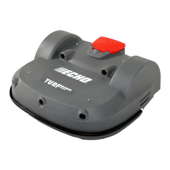
Chapter 4 Turfmow 1000 description 4.1 The robot Turfmow 1000 components Figure 2: Top view of robot components (1) STOP button Hitting this button will stop the robot at any point. It is also a lid that provides access to the so-called smart box that contains the on board computer that controls the operation of the robot. - Page 12 Chapter 4 Turfmow 1000 description Figure 3: Bottom view of robot components (8) Cutting heads The robot is fitted with 3 rotating cutting heads. Each cutting head is equipped with three cutting blades, which are rotated on the head and which cut the grass. Figure 4: Detail of the cutting head (A) Bracket (B) Cable entry...
- Page 13 Chapter 4 Turfmow 1000 description The cutting blades need to be replaced on a regular basis to ensure optimal mowing performance. The height of the cutting head determines the length of grass that is cut. This can be adapted to match the required conditions. See setting the cutting height (page 105).
- Page 14 Chapter 4 Turfmow 1000 description Options The wheel brushes are an optional extra that are installed behind the rear wheels to clean them. Installing the wheel brushes (page 72) Dimensions Figure 7: Rear view dimensions Figure 8: Side view dimensions Turfmow 1000 Technician's Manual Version: Release 3.5 Last updated: 2018-12-20...
-
Page 15: The Charging Station
Chapter 4 Turfmow 1000 description Figure 9: Bottom view dimensions Technical details For detailed technical specifications see Technical specifications Turfmow 1000 (page 194). Sound level: The A-weighted emission sound pressure level at the operator position does not exceed 70 dB(A). Mass in kilograms: This can be seen on the identification label. - Page 16 Chapter 4 Turfmow 1000 description (3) Occupation sensor. This is an optional feature indicating that the charging station is occupied in charging a robot. This is useful when there are multiple robots in the field. Figure 11: Rear view of the charging station (4) LED display which indicates the current state of the station: •...
-
Page 17: The Station Positioning Beacon
Chapter 4 Turfmow 1000 description Warning: Always unplug the charging station before opening it. In those situations where there is no plug, remove the fuse from the charging station. 4.3 The station positioning beacon The station positioning beacon is a device that emits a UWB (Ultra Wide Band) signal, which is detected by the robot. -
Page 18: Sensors
Chapter 5 Sensors 5 Sensors Turfmow 1000 is equipped with a comprehensive set of sensors that ensure its safe operation. These sensors ensure that the robot can detect, and react if an obstacle lies in its path or if a small object is in danger of being damaged by the cutting blades. Stop button The stop button is easily visible, situated on the top of the robot (see Figure 2: Top view of... - Page 19 Chapter 5 Sensors Lift and body displacement sensors Figure 14: Location of the lift sensor attachments Figure 15: Lift sensors Lift sensors are attached to the body of the robot at 4 points. If the robot touches a low object which pushes the bodywork up or if someone tries to lift the body work, the lift sensors will react.
- Page 20 Chapter 5 Sensors The location of the coil can be seen as item (11) in Figure 3: Bottom view of robot components (page 12). Station positioning beacon The station positioning beacon is a transceiver that emits an Ultra Wide Band (UWB) signal. A receiver is located in the robot.
-
Page 21: How Turfmow 1000 Works
Chapter 6 How Turfmow 1000 works 6 How Turfmow 1000 works The robot works in a number of 'states'. Within these states it is programmed to operate in a number of 'modes'. Figure 16: Operating states Autonomous mission (page 22): In this state the robot operates in cycles in which it works, (cutting the grass), or is in the charging station to charge the battery or for a rest period. -
Page 22: Autonomous Mission State
Chapter 6 How Turfmow 1000 works 6.1 Autonomous mission state Figure 17: Autonomous mission state Work In this mode the robot mows the grass in a random fashion. For more details see Work mode (page 23). Go to station At a certain moment, which depends on the program and the current conditions, the robot will make the decision to move to the charging station. -
Page 23: Work Mode
Chapter 6 How Turfmow 1000 works 6.1.1 Work mode rect 102,19,183,61 Go zone mode (page 31) Figure 18: Work mode When in work mode mows the grass in the field (inside the peripheral wire). It executes a random movement over the field to ensure that the whole field is covered and that the robot's wheels do not leave traces on the grass. - Page 24 Chapter 6 How Turfmow 1000 works continue in a new direction. This angle is typically between 108° and 172°, and will depend on the settings defined in the software. The minimum and maximum bounce angles are set in the Technician's menu (page 114) in the user interface.
-
Page 25: Go To Charging Station Mode
Chapter 6 How Turfmow 1000 works 6.1.2 Go to charging station mode Figure 21: Go to station mode Whilst working, the robot checks the current conditions and its programmed instructions. These conditions could be: • The battery needs charging, • The programmed mowing time has ended, (In the case of multi-field installations, this corresponds to the mowing schedule for the parcel in which the robot is currently mowing.) •... - Page 26 Chapter 6 How Turfmow 1000 works At a certain point (A), the robot will decide it needs to return to the charging station. It will then proceed to the nearest point B that lies within the "track border" (page 201). The robot then follows the track border until it reaches point C where it is at a certain distance from the charging station.
- Page 27 Chapter 6 How Turfmow 1000 works At point A, the robot decides it needs to return to the charging station. It moves towards the track border in "Parcel R" and then follows "Track border R" until it reaches point B, which is where the two fields overlap.
- Page 28 Chapter 6 How Turfmow 1000 works Figure 22: Return to station using a station loop At point A, the robot decides to return to the charging station. It then moves towards the track border (page 201) and follows the track border of the single mowing field until it reaches point B, which is where the two wires overlap.
-
Page 29: Charge Mode
Chapter 6 How Turfmow 1000 works At point A, the robot decides it needs to return to the charging station. It moves towards the track border in "Parcel R" and then follows "Track border R" until it reaches point B, which is where the two fields overlap. -
Page 30: Wait In Charging Station Mode
Chapter 6 How Turfmow 1000 works 6.1.4 Wait in charging station mode Figure 24: Wait in station mode Decisions C The robot will stay in the charging station once the battery has been charged until: • the normal program needs to commence, •... -
Page 31: Go Zone Mode
Chapter 6 How Turfmow 1000 works When the robot is operating in border mode, it moves directly over the peripheral wire. The robot may well be programmed to operate in border mode after it has left the charging station and before it starts mowing with the random movements of the work mode. The number of times per week the border mode is implemented is set as an operating parameter... - Page 32 Chapter 6 How Turfmow 1000 works The robot leaves the station and follows the wire (trackwire movement (page 202)) until it reaches point A. At point A it executes the loopstep (page 200) move, turning through 90 and moving into the trackborder (page 201).
- Page 33 Chapter 6 How Turfmow 1000 works In all cases the robot will leave the station and follow the wire for a certain distance until it reaches point A. It will then execute the loopstep and turn through a right angle and take up its position in the track border of the first parcel (point B).
- Page 34 Chapter 6 How Turfmow 1000 works When the robot leaves the station it follows the station loop wire, until it reaches point A. This is a pre-defined distance within the main field peripheral wire. At this point it will turn and follow the track border of the field to be mowed until it reaches point B, when it will turn into the field and start mowing.
-
Page 35: Inactive State
Chapter 6 How Turfmow 1000 works When the robot leaves the station it follows the station loop wire, until it reaches point A. This is a pre-defined distance within the main field peripheral wire. At this point it will turn and follow the track border of the field connected to the station loop until it reaches point B, which is where the two mowing fields overlap. -
Page 36: Service State
Chapter 6 How Turfmow 1000 works • Case 2: the mission has been manually stopped and the robot will enter the Standby mode (page 36). Case 1: Alarm mode When the robot encounters a problem, such as a cutting head that is blocked, it will register alarm (page 130) and enter the inactive state. - Page 37 Chapter 6 How Turfmow 1000 works Maintenance test A set of maintenance tests are available from the Service menu (page 121) in the Technician's menu (page 114). Install Wizard This is used to set installation parameters. See Configuration (page 73). Note: The Installation Wizard can only be used for a mono-field installation using a positioning beacon.
-
Page 38: Installation
Chapter 7 Installation 7 Installation The figure below illustrates the basic components of an installation. Figure 28: Components of an installation An area to be mowed (parcel), which is contained within the complete site, is defined by a peripheral wire. There can be more than one peripheral wire, thus defining multiple fields as shown in the example below. -
Page 39: The Charging Station
Chapter 7 Installation General installation procedure The general installation procedure consists of the following steps: Choose the best location for the charging station and position it. Decide how the peripheral wire is to be laid taking into account the characteristics of the site and the obstacles. -
Page 40: Station Return And Exit With A Positioning Beacon
Chapter 7 Installation Note: The charging station may only be connected to a supply circuit protected by a residual current device (RCD) with a tripping current of not more than 30mA, 7.1.2 Station return and exit with a positioning beacon An overview of the return to station manoeuvres for different types of installation can be found in return to station in a single mowing field... -
Page 41: Return To Station With A Station Loop
Chapter 7 Installation The robot then moves along the trackborder to point F where it turns into the field to start mowing. The distance between points E and F is set by the > parameter. Start Zone Distance The limits on the angle taken to turn into the field is set by the >... -
Page 42: Dimensions Associated With The Charging Station
Chapter 7 Installation 7.1.4 Dimensions associated with the charging station Figure 31: Distance between the charging station and the peripheral wire Distance between the charging station and the peripheral wire: 0.57m Figure 32: Dimensions associated with the charging station 7.1.5 Critical distances for a straight wire Note: These distances apply to the situation where a positioning beacon is used to detect the charging station. - Page 43 Chapter 7 Installation Minimum distance between peripheral wires. Critical distances for an S-Shaped wire (Case 1) The figure below illustrates the case where the robot can not detect the positioning signal until after it has passed point A. Point A represents the minimum distance on the vertical section of the wire required for the robot to perform the loopstep manoeuvre.
-
Page 44: Placement Of The Charging Station
Chapter 7 Installation 7.1.6 Placement of the charging station The position of the charging station must ensure that when the robot is in place: • The height of the arms has been set to make good contact between the charging station and the contacts on the robot. - Page 45 Chapter 7 Installation Figure 36: Components on the charging station board (1) JLED Pilot LED (2) JREL Relay connection (optional) (3) JDET Presence detection (optional) (4) JSERIAL PC interface for updates (5) JWIRE Peripheral wire (6) JTR1 DC supply (-) (7) JTR2 DC supply (+) (8) JCHRG...
-
Page 46: Installing A Channel Board Outside Of The Charging Station
Chapter 7 Installation - Channel 9 is reserved for a station used for charging only and which does not generate a signal. 7.1.8 Installing a channel board outside of the charging station When using multiple wires (fields), if a wire is located at a significant distance from the charging station, it may be necessary to install a channel board closer to the field rather than in the charging station. -
Page 47: Selection Of Charging Station Type (On The Positioning Beacon Board)
Chapter 7 Installation Figure 38: Inductor The inductor must be placed in series with the peripheral wire. One end must be connected to the station board. The other end is connected to the peripheral wire. 7.1.10 Selection of charging station type (on the positioning beacon board) The figure below shows the bank of 8 switches on the positioning beacon board, and the direction used for ON and OFF. -
Page 48: Installing The Peripheral Wire
Chapter 7 Installation Switch Always Never TM2000 Ball TM1000 Never accepted Picker accepted accepted Never Always TM2000 Ball TM1000 Always Picker accepted accepted accepted 7.2 Installing the peripheral wire This chapter describes the installation requirements and considerations for the peripheral wire. - Page 49 Chapter 7 Installation Minimum length Minimum length of the peripheral wire: 200m Note: If a minimum length of 200m is not possible, it is necessary to add an inductor in series with the wire (page 46). Maximum length Maximum length of the peripheral wire: 1200m A second charging station is recommended: •...
- Page 50 Chapter 7 Installation Distances between the peripheral wire and boundary of the area to be mowed The peripheral wire is set within the boundary of the area to be mowed (field) as shown in Figure 28: Components of an installation (page 38).
- Page 51 Chapter 7 Installation Figure 47: Site with narrow strait There is a required minimum width of the strait, the value of which depends on the length of the strait. If this minimum width is not available, when the robot is in Zone B it will not be able to pass through the strait and return to the charging station.
-
Page 52: Dealing With Obstacles
Chapter 7 Installation Wire installation good practice Note: It is essential to use the wire supplied by Echo EU. Begin setting up the wire from the charging station. It is recommended to lay the main wire in a clockwise direction and the wire of an island in the opposite (counter-clockwise) direction. - Page 53 Chapter 7 Installation - the distance between the obstacles (3), - the size of the obstacle (4). These distances are illustrated in the figure below. Figure 50: Location of obstacles (1) Distance between the obstacle and the charging station when this is MORE than 15m -> use an island (page 58).
- Page 54 Chapter 7 Installation 7.2.1.1 Types of obstacles Obstacles that must be accommodated include: - Trees and other planted areas (flowerbeds). - Sculptures. - Garden items such as swings, climbing frames, trampolines... - Paths and terraces. - Ponds and swimming pools. Trees Figure 52: Trees with roots that go straight down into the ground Large trees with roots that go straight down into the ground, without surface roots, can...
- Page 55 Chapter 7 Installation Figure 54: Large trees with surface roots Important: When the trees have surface roots, an island (page 58) or pseudo island (page 59) must be used. Figure 55: Sapling Trees with very small trunks need to be protected with poles that the sensors can detect. Turfmow 1000 Technician's Manual Version: Release 3.5 Last updated: 2018-12-20...
- Page 56 Chapter 7 Installation Garden items Figure 56: Swing The sonar waves from swing supports are likely to be reflected to the sky. Protection poles would be too dangerous for children, so the solution is to use an island or pseudo-island. Figure 57: Trampoline The robot can detect the horizontal mattress on a trampoline if it is at a height of more than 400mm.
- Page 57 Chapter 7 Installation If the sonar sensors cannot detect the sculpture from some directions, put protection poles around the sculpture. If this is not acceptable for aesthetic reasons, the sculptures should be treated as an island or a pseudo-island depending on their location. Water The treatment of water features such as ponds or pools requires special considerations.
- Page 58 Chapter 7 Installation 7.2.1.2 Islands Islands are loops in the peripheral wire around permanent obstacles. Note: A maximum of 5 islands can be installed! This is to save time while returning to the charging station AND to avoid bouncing off from island to island.
- Page 59 Chapter 7 Installation Figure 60: Wiring for an island The robot will move across the pair of wires. Figure 61: Robot route 7.2.1.3 Pseudo-islands Pseudo-islands are loops in the peripheral wire around permanent obstacles. Pseudo-islands can be created when the obstacle is: - less than 5m from the peripheral wire - less than 15m from the charging station - less than 5m from another island or pseudo-island...
-
Page 60: Installing Multi-Fields
Chapter 7 Installation Figure 62: Route of the peripheral wire around a pseudo-island Note: The wire must be laid around a pseudo-island in the opposite direction to which it is laid around the field. It is recommended that, the peripheral wire is laid around the field in a clockwise direction from the charging station. - Page 61 Chapter 7 Installation • Each pair of wires/parcels which overlap must be designated as neighboring parcels. Multi-fields can be used - to manage large complex mowing areas, - to provide a means to return the robot to the charge station without the need for the positioning beacon.
- Page 62 Chapter 7 Installation Figure 65: Dimensions of overlaps • The length of the overlap must be more than 3m. • The width of the overlap must be more than 2.5m. Installing the peripheral wires Important: The installation of the peripheral wire should take into account all the principles set out in Installing the peripheral wire (page 48).
-
Page 63: Installing The Positioning Beacon
Chapter 7 Installation 7.4 Installing the positioning beacon The positioning beacon is a device that emits an UWB (Ultra Wide Band) signal, which is detected by the robot, and which enables it to locate the charging station to a high degree of accuracy. -
Page 64: Installing The Positioning Board In The Charging Station
Chapter 7 Installation 7.4.1 Installing the positioning board in the charging station The positioning beacon board is most commonly installed inside the charging station, as shown in the figure below. Figure 67: Location of the positioning board in the charging station To install a positioning beacon board in the charging station Disconnect the power from the charging station. - Page 65 Chapter 7 Installation Verify that all the LEDs indicate that there is no power connected. The board must be located on the three supports shown in Figure 66: Components on the positioning signal board (page 63). Note: One of these should be a metal grounded support. See Upgrade the positioning board supports (page 69).
-
Page 66: Installing The Positioning Board Outside Of The Charging Station
Chapter 7 Installation 7.4.2 Installing the positioning board outside of the charging station Depending on the layout of the site, there are situations when the positioning beacon inside a station might not be seen properly by the robot. In such situations the problems can be resolved by locating the positioning beacon outside of the charging station. - Page 67 Chapter 7 Installation Locate the positioning board in the box, by gently pressing it onto the four plastic spacers. Pass the cable through the cable gland. Make sure that the cable gland is properly tightened. Connect the cable to the socket on the positioning board. Turfmow 1000 Technician's Manual Version: Release 3.5 Last updated: 2018-12-20...
-
Page 68: Changing The Positioning Board And Components
Chapter 7 Installation Attach the box to its support using the appropriate screw. (Diam. 4.0-4.5mm / head 7.5-8.0mm) Connect the other end of the cable to the power supply. Configure the settings. (Use the technician's menu (page 114) > Infrastructure Stations 7.4.3 Changing the positioning board and components This document describes how to upgrade the positioning board and its components. - Page 69 Chapter 7 Installation To change the positioning beacon board Disconnect the power cable from the positioning board. Gently press the locking guard, then pull the cable out of the socket. Remove the three plastic braces by gently pressing them with your fingers and unscrewing the socket cap hex screw (3mm, nut 7mm).
- Page 70 Chapter 7 Installation (1) Hex M/F spacer screw (P/N: YB-012-00009-0A) (2) Locking washer (P/N: YB-701-04000-0A). (3) Hex cap socket screw (P/N: YB-506-04006-0A) Remove the bottom left plastic support; and replace it with a metallic connection. Replace the power cable between the positioning board and the wire board The power cable connects power from the connection on the wire board to the connection on the positioning board.
-
Page 71: Slopes
Chapter 7 Installation Connect the new cable to the wire board. Ensure the wire is properly screwed and secured. Take the cable behind the wire and positioning boards and connect the other end into the socket on the positioning board. 7.5 Slopes Note: A situation where the entire site is on a severe slope is not suitable for Echo EU robots. -
Page 72: Installing The Wheel Brushes
Chapter 7 Installation Figure 69: Longitudinal slope of the charging station The transversal slope should be a maximum of 10% (6 °). Figure 70: Transversal slope of the charging station 7.6 Installing the wheel brushes The wheel brushes are fixed to the body behind the rear wheels. The installation kit contains the following items. -
Page 73: Configuration
Chapter 7 Installation Position the brushes on the brackets as shown in the figure below, aligning the slots in the brush with the screw holes in the bracket. Screw the brushes onto the bracket, inserting the flat washer next to the brush and the crinkled washer below the screw head. - Page 74 Chapter 7 Installation Configuration parameters set by the wizard The installation parameters that can be detected and set are: • The positioning beacon parameters so that the robot can communicate with the station where it needs to go to be charged. •...
- Page 75 Chapter 7 Installation The first stage of the process is to search for the signal on the peripheral wire as set using the rotating switch inside the charging station. It will request confirmation that the robot has been positioned inside the wire. With highlighted, press Next The next stage is to search for the positioning beacon in the installed charging station.
- Page 76 Chapter 7 Installation Figure 72: Minimum and Maximum distances for the trackwire movement leaving the station 10. Edit the values if necessary, then highlight and press Confirm 11. The wizard will then ask you on which side of the robot the charging station is located. Press the Left or the Right button accordingly the press 12.
- Page 77 Chapter 7 Installation The movements are illustrated in the figure below. Figure 74: Movement of the robot back to the starting point - The robot moves out of the station along the wire for about 50cm. - It then turns through a right angle away from the wire. - It turns through another right angle to go in the direction of the starting point.
-
Page 78: Configuration Using The Menus
Chapter 7 Installation 7.7.2 Configuration using the menus Once the peripheral wire(s) and the station have been set in place, the installation needs to be configured. All configuration settings are defined in the Technician's menu (page 114). General configuration procedure using a positioning beacon •... - Page 79 Chapter 7 Installation Note: Access parameters only need to be defined if the robot is using a positioning beacon to return to the charging station. Note: A set of access parameters must be defined for each station and each wire. Wire The id of the peripheral wire to which the parameters apply.
- Page 80 Chapter 7 Installation Figure 77: Minimum and Maximum Exit Distances 7.7.2.2 Start zones Start zones define where and how the robot starts mowing. • A start zone is defined for a parcel. • A start zone can be defined for a station that contains a positioning beacon. •...
- Page 81 Chapter 7 Installation Figure 78: Start zone direction from station with positioning beacon When the robot leaves the station, it follows the station loop until it for a pre-defined distance until it arrives in the track border of a mowing field. It then takes the specified direction.
-
Page 82: Installation Examples
Chapter 7 Installation If the start zone is located in a different parcel than the one containing the charging station, the distances are measured from the entry point into the parcel. This is shown in the figure below. Figure 80: Minimum and Maximum Start zone distances from entry into parcel Angle Min. - Page 83 Chapter 7 Installation 7.8.1.1 Peripheral wire Wire around the whole field In the example shown below the peripheral wire surrounds the entire field. This configuration requires that the goal nets are lifted up before mowing. Figure 82: Wire around whole field Peripheral wire in front of goals In the example shown below, the peripheral wire loops in front of the goals.
- Page 84 Chapter 7 Installation Note: In this example it is assumed that the charging station contains a positioning beacon. The return to the station will be S-shaped and can be clockwise or counter-clockwise. Figure 84: Charging station beside the field without a handrail Configuration parameters This example assumes the use of a positioning beacon.
- Page 85 Chapter 7 Installation 14. Set the station exit distances. Select > . Recommended Access param. Min / Max exit dist values are 5m min and 10m max. 7.8.1.3 Charging station behind panels/ fence With positioning beacon In this case the charging station is located behind the fence in a large enclosure. The figure below shows the layout of the peripheral wire and the route taken by the robot to enter and leave the station.
- Page 86 Chapter 7 Installation With station loop Figure 86: Charging station in behind fence with station loop 7.8.1.4 Charging station in an enclosure sheltered by the field fence An illustration of this situation is shown in the figure below. The lower part of the fence has been cut to allow the robot to enter the enclosure.
-
Page 87: Mono-Field With Two Start Zones
Chapter 7 Installation Figure 88: Critical dimensions for a small enclosure 7.8.2 Mono-field with two start zones This is an example of an installation that might be used in a large garden with two areas. Even though it is set up as a single field, two start zones are used to ensure that the robot starts mowing in both areas on a regular basis. -
Page 88: Return To Station With A Station Loop
Chapter 7 Installation Select > > Infrastructure Peripheral wires Wire CH{X} Set the signal channel. Select . Enter the number of the switch set using the rotating switch in the Signal channel charging station (page 44). Check the distance value displayed at the top of the screen. This value should be positive. - Page 89 Chapter 7 Installation The wire "Lawn" is configured for the robot to mow normally. When it returns to the charging station it will follow the trackborder until it reaches the station "Loop" wire. It will then follow the wire until it reaches the station. Figure 90: Dimensions of the station loop •...
-
Page 90: Complex Garden And With Station Loop
Chapter 7 Installation Configuration Configuration of this installation must be done using the menus. The instructions given below are the minimum set of configuration parameters that must be set for this type of installation. For information on all the configuration parameters available see the Technician's menu (page 114). - Page 91 Chapter 7 Installation Figure 93: Multi-field installation for a complex garden The details of this installation are listed below: • The station is connected to a station return loop. • The station return loop overlaps with Wire 1 and Wire 2. •...
- Page 92 Chapter 7 Installation 10. Select Parcels 11. Select the parcel associated with the LOOP wire. 12. Select and check the button OFF. This ensures that when the robot is in Use trackborder this field, it will just follow the wire to reach the station. 13.
-
Page 93: Using Your Robot
Chapter 8 Using your robot 8 Using your robot Before using the robot refer to the Safety measures (page 93). There are a number of security icons (page 94) on the robot and it is important that you understand what each of them means and respect all of them. To ensure optimal operation of your robot, it is important that it is well maintained and serviced... -
Page 94: Safety Notices
Chapter 8 Using your robot • Take care of your footing on slopes. • Always walk, never run. Important: Always wear substantial footwear and long trousers while operating the machine. Note: The operator or user is responsible for accidents or hazards occurring to other people or their property. - Page 95 Chapter 8 Using your robot Handling the machine: Never place hands or feet under or near the machine when it is operation. Stop the machine: Always stop the machine and wait for the cutting blades to stop before handling the machine. Operate the disabling device (ON/OFF switch) before working on or lifting the machine.
-
Page 96: The User Interface
Chapter 8 Using your robot Lock: The robot is equipped with an anti-theft system. 8.3 The user interface A smart box, which contains the on-board computer to manage the operations of your robot, is located under the Stop button lid. Note: The robot needs to switched ON before you can use any of the functions available from the interface. - Page 97 Chapter 8 Using your robot Figure 94: Components of the user interface The configuration interface consists of the following components: (1) The numeric buttons These are used to select menu choices and enter numeric values. (2) LED screen Displays current situation. See The LED screen (page 98).
-
Page 98: Using The Interface
Chapter 8 Using your robot The LED screen Name The name of the robot. To change the robot name (page 111). WiFi /Mobile connection indicates that the robot is connected as WiFi client. When it is blinking it is trying to connect. -
Page 99: The Actions Menu
Chapter 8 Using your robot To connect the robot as a WiFi client (page 110). This operation allows you to monitor the state of the robot and to upload new software. To setup the robot as a WiFi network Access Point. (page 120) Settings To set the time zone and the language used for the menus... -
Page 100: The Settings Menu
Chapter 8 Using your robot Note: If the lid is not closed within 10 seconds, the operation is canceled and you will need to repeat this procedure. Note: If the operation does not start even if the lid appears to the closed see Correcting lid closure problems (page 189). - Page 101 Chapter 8 Using your robot Cutting heads Enable/disable specific cutting heads (page 103). Border Sets the number of times the border mode is used each week (page 104). Note: This option is only available for a single field installation which uses a positioning beacon to locate the charging station.
- Page 102 Chapter 8 Using your robot To edit the schedule, highlight the parcel and press Use the left and right arrows to select the required day of the week, then press Use the down arrows to select the required period in the day, and press Use the numeric keyboard to enter the start and end time values where the cursor is flashing then press Press the down arrow key to select the active check box.
- Page 103 Chapter 8 Using your robot 12. Use the arrows to select . Press to check the button ON to ensure that the Follow sched. robot follows the defined schedule. When unchecked, the robot will ignore the timetable and work continuously. To copy the schedule from one day to another Follow the procedure above to define the mowing schedule for one day.
- Page 104 Chapter 8 Using your robot This figure indicates that all the cutting heads are enabled. Press the number key(s) that corresponds to the cutting head(s) you wish to enable/ disable. Note: Pressing on the numeric keypad will select all the cutting heads. Press Press to return to the main menu.
- Page 105 Chapter 8 Using your robot Press Press to return to the main menu. Cutting height This command sets the height of the blades. When using the robot for the first time in the season or after being switched off for several days, the grass may be too dense or too high. In this case it is recommended that you increase the mowing height for a few days before gradually reducing it again.
- Page 106 Chapter 8 Using your robot System locking This command enables you to block the use of the robot. This is useful if the field area is in use during the time when the robot is scheduled to be mowing. The robot will remain inactive until the system is unblocked.
-
Page 107: The Service Settings Menu
Chapter 8 Using your robot Press the right arrow buttons to change the contrast Press the up and down arrows to highlight . When this option Temperature Auto Adj is checked ON, the LCD contrast is automatically adjusted according to the ambient temperature. - Page 108 Chapter 8 Using your robot Press to accept the time zone. Press to exit the menu. Language To set the language Press Press the arrow keys to highlight then press Regional parameters Press the down arrow to highlight Language Press Use the left and right arrow keys to highlight the required language.
- Page 109 Chapter 8 Using your robot IP address This displays the current IP address of the robot, depending on the mode in which the robot is operating. Modes can be mobile, vpn, wifi (image01) Mode Allows you to set the mode in which the robot is to operate. This can be: The robot will not be connected to a network.
- Page 110 Chapter 8 Using your robot Using the robot as a client For normal operation it is recommended that you set up the robot as a WiFi client. This will enable it to communicate with the portal on the web-server. To set up the robot as a client Press Highlight and press...
- Page 111 Chapter 8 Using your robot Robot Name By default the name of the robot corresponds to the serial number. To change the name of the robot Press Press the arrow keys to highlight then press Device info Highlight and press Robot name Highlight the back arrow to delete the current name.
- Page 112 Chapter 8 Using your robot Radius Current radius of the Geofence security zone (page 113) Dist. to beacon Current distance in meters between the robot and the positioning beacon. A message is displayed if no positioning beacon is installed. If this field displays "infinity", it means it is not able to detect the beacon. Magnetic distance The distance between the robot and the peripheral wire.
- Page 113 Chapter 8 Using your robot Enable pin code Highlight the check box. Press to toggle the setting. Enable PIN code OFF Enable PIN code ON Press to accept the new setting. From now on certain commands will require the PIN code to be entered before they can be executed.
-
Page 114: Technician's Menu
Chapter 8 Using your robot to highlight , then press Radius value Use the numeric keypad to enter the required value. 10. Press to return to the main menu. 8.4 Technician's menu To access this menu, press 9 for a number of seconds. The following menus are provided: Infrastructure (page 115) -
Page 115: Infrastructure
Chapter 8 Using your robot 8.4.2 Infrastructure The operations available from this menu are used to configure the robot's installation in the field. See also: Installation examples (page 82) • Peripheral wires (page 115) • Parcels (page 116) • Stations (page 118) 8.4.2.1 Peripheral wires This schedules the "Wires Setting"... - Page 116 Chapter 8 Using your robot 8.4.2.1.2 Create a new wire To create a new wire Select > > Infrastructure Peripheral wires Create new wire Select to confirm that you want to create the new wire. The new wire and its associated parcel will appear in the wire settings list. Select the new wire and click on Select the required channel number.
- Page 117 Chapter 8 Using your robot Figure 95: Return direction parameter The current return direction is indicated in the list of parcels. The figure below illustrates the advantage of setting different return directions in different parcels to facilitate the most efficient way for the robot to return to the charging station. Figure 96: Parcel return directions Use trackborder This parameter defines whether the robot uses the...
- Page 118 Chapter 8 Using your robot Note: A general rule is that the maximum value of the track border = distance between the peripheral wires / 5m. If the distance between the wires is less than 15m, the maximum value of the track border must be accordingly reduced. Min.
- Page 119 Chapter 8 Using your robot Existing stations If stations have already been defined a list of them is presented. For stations associated with a positioning beacon, selecting the station enables you to view the properties of the station (page 119) and to configure the way that the robot enters and leaves the station.
-
Page 120: Mobile Connection
Chapter 8 Using your robot Distance Displays the distance between the robot and the selected station. Charge Defines whether the station is used to charge the robot or not. Software version The current version of the software for the station. Connected to parcels This defines to which of the defined parcels the station is connected. -
Page 121: Demonstration
Chapter 8 Using your robot Displays the current id of the Access Point Name of the SIM card. Click on to edit the name. The alphanumeric keyboard is scheduled from which you can delete the current id and enter a new one. Select each character in turn, press "V", then press to accept it. - Page 122 Chapter 8 Using your robot - a cutting head has been replaced, - the belt lifting the cutting heads has been modified or replaced. During the calibration procedure the cutting heads are lifted until they reach their maximum height. Their position during this movement is termed the "raw position" and when the maximum height is reached, it is termed the "homing position"...
- Page 123 Chapter 8 Using your robot Detect This displays whether the robot can detect a voltage on the left and right sides. KO means it can not detect a voltage on the left or right side. OK means that it can detect a voltage.
- Page 124 Chapter 8 Using your robot To test the Smartbox Follow each of the instructions as they appear on the screen. Press to answer Yes to a question and to answer NO. If the item being tested is operating correctly it will disappear from the list. If there is a problem with any of the items, the Smartbox should be replaced.
- Page 125 Chapter 8 Using your robot The following information is shown. X/Y BACK_SENSORS X represents the current test in the current sequence. Y represents the total number of tests to be performed in the current sequence. BACK_SENSORS is the name of the current test. Activate sensors The number of sensors that need to be tested by activating them.
- Page 126 Chapter 8 Using your robot Close the lid when requested. The robot will move forward a short distance then stop and beep. Open the lid. If the robot moved forward, answer Yes to the question by clicking If the robot moved backwards answer No to the question by clicking .
- Page 127 Chapter 8 Using your robot When the 2mm gauge is in place, close the lid and press down gently to ensure that the lid is touching the gauge. At the end of the test, if the test failed, the problems are indicated through the following messages: •...
-
Page 128: Technician Settings Advanced Parameters
Chapter 8 Using your robot - Relay NO (Normally Open) must be placed on the top. This relay is indicated by the digit 1 in the reference number on the relay. - Relay NC (Normally Closed) must be placed on the bottom. This relay is indicated by the digit 4 in the reference number on the relay. - Page 129 Chapter 8 Using your robot Wire CH# A list of currently defined peripheral wires. For each wire the following is displayed: - the current magnetic distance between the robot and the wire. - An indication of the shape of the pulse emitted on this signal channel, or whether a this channel is connected.
-
Page 130: Troubleshooting (Error Messages)
Chapter 9 Troubleshooting (Error messages) 9 Troubleshooting (Error messages) An alphabetical list of error messages. • Bad battery connection (page 131) • Bad battery measure (page 132) • Battery over voltage (page 131) • Battery temperature issue (page 131) • BMS communication wire is not connected (page 132) •... -
Page 131: Battery
Chapter 9 Troubleshooting (Error messages) • Unlock system : bad pin code (page 137) • Wait for 5 Seconds of full contact (page 141) • Wait for no collision (page 145) • Waiting for signal (page 141) • Waiting for station contact (page 141) •... -
Page 132: Bad Battery Measure
Chapter 9 Troubleshooting (Error messages) Check that the screws indicated are properly tight. Or: Change the battery. 9.1.4 Bad battery measure Scenario Occurs when the values displayed for the battery on the GUI screen do not correspond to the actual values. Solution Take a photo of the GUI screen and report the problem to your dealer. -
Page 133: Shutdown In 2Min / Inhibit Shutdown Principal / Unblock Brakes
Chapter 9 Troubleshooting (Error messages) Take a photo of the GUI screen and report the problem to your dealer. (Note the date, time and robot S/N). 9.1.6 Shutdown in 2min / inhibit shutdown principal / unblock brakes Symptoms / Observations - The GUI screen displays the alarm- and asks if you want to inhibit the shutdown, - The LED is blinking very fast (~5x/s) - The brakes are deactivated. -
Page 134: Station Contact Lost For {0}S
Chapter 9 Troubleshooting (Error messages) Check that the installation of the peripheral wire is correct. If all of the above conditions are met, and the robot still fails to detect the positioning beacon, consider installing a "return to station loop". See Installing multi-fields (page 60). -
Page 135: The Robot Has No Parcel To Mow. Please Configure Least One Parcel
Chapter 9 Troubleshooting (Error messages) Meaning / Reason At least one wire, defining a field to be mowed, must be configured. Solution Check the installation configuration settings. See Configuration using the menus (page 78). 9.2.6 The robot has no parcel to mow. Please configure least one parcel. -
Page 136: No Station Found In Any Field
Chapter 9 Troubleshooting (Error messages) Solution Check there is no obstacle between the point where the robot performed the loopstep and the station. Check the charging station power supply. Check the DC voltage on station arms (should be 32V). Check station alignment to the wire. The charging station arms should be approximately at right angles to the direction of the peripheral wire. -
Page 137: Interface
Chapter 9 Troubleshooting (Error messages) 9.3 Interface 9.3.1 Unlock system : bad pin code Scenario "System blocking" is set and must be unblocked by entering a pin code. An incorrect code has been entered. Solution Enter the correct code. If this is not known, contact technical support. 9.4 Operational 9.4.1 Unable to find the working area Scenario... -
Page 138: Failed To Dock To Station
Chapter 9 Troubleshooting (Error messages) Check and clean contacts. 9.4.3 Failed to dock to station Scenario The machine has tried to return to station but failed. Solution Check there is no obstacle next to the station. Check station power supply. Check DC voltage on station arms (should be 32V). -
Page 139: Motor Blocked When Going {0} To {1}Mm
Chapter 9 Troubleshooting (Error messages) - the motor 9.4.6 Motor blocked when going {0} to {1}mm Scenario Occurs after a command to change the cutting height has been issued, but the cutting head can not move. Meaning / Reason The motor lifting the cutting head is not working. Solution Remove the cover on the motor. -
Page 140: The {L/R} Fuse Is Blown Or The {L/R} Motor Is Not Connected
Chapter 9 Troubleshooting (Error messages) 9.4.9 The {L/R} fuse is blown or the {L/R} motor is not connected. Scenario Occurs if the robot can not detect any current in either the Left or the Right wheel motor. Meaning / Reason Either a fuse or a connection is faulty. -
Page 141: Waiting For Station Contact
Chapter 9 Troubleshooting (Error messages) parameter in the Technician's menu (page 114) . > . If the Infrastructure Parcels phase on the loop circuit is incorrect, the robot will turn in the wrong direction to enter and exit the station. Check the area around the charging station and remove any obstacles. -
Page 142: Obstacles
Chapter 9 Troubleshooting (Error messages) 9.5 Obstacles 9.5.1 Noise on bumper Scenario Occurs when the electrical (background) noise level on the bumper is high enough to impair the proper operation. Solution This only occurs when the robot is at the charging station. Check that the station is properly grounded. -
Page 143: Unhandled Collision Event
Chapter 9 Troubleshooting (Error messages) Solution Remove the obstacles. If this error continues to appear, re-consider the installation and create islands/ pseudo islands around the obstacles. See Dealing with obstacles (page 52). 9.5.4 Unhandled collision event ! Scenario Occurs when the robot has encountered small obstacles . Meaning / Reason The robot has detected small obstacles in the mowing field, which are not large enough to trigger the operation of the lift sensors. -
Page 144: Dma Error, On Sonars : {0
Chapter 9 Troubleshooting (Error messages) Meaning / Reason Obstacle too close to the charging station. Solution Remove any obstacles If a "return to station" loop is being used, check that the robot is turning in the correct direction in order to enter the station. The direction is set as a configuration parameter in the Technician's menu (page 114) . -
Page 145: Wait For No Collision
Chapter 9 Troubleshooting (Error messages) 9.5.11 Wait for no collision Scenario Occurs after a collision. The robot moves backwards and then checks if the obstacle is still there. It will then wait until the obstacle has been removed. This message appears while it is waiting. -
Page 146: Connecting To Robots
Chapter 10 Connecting to robots 10 Connecting to robots Communication with a robot is available through: • Hands-on human-machine interaction (page 146) • Remote access via the web server (page 146). Hands-on human-machine interaction Figure 100: Human Machine Interaction This type of communication refers to the direct operation of the robot using the user interface provided. -
Page 147: Entities, Users And Robots
"FAQ" page. - Monitor the performance of the robot. - Implement automatic software updates under the control of Yamabiko. 10.1.1 Entities, users and robots Figure 104: Entities users and robots Turfmow 1000 Technician's Manual Version: Release 3.5... -
Page 148: Creating Accounts
Chapter 10 Connecting to robots There are 5 entities in the example above that are related in a hierarchical structure. The parent entity is the "City Authority". It has 4 child entities ("Sports Field 1", "Sports Field 2", "Park West" and "Park East"). The entity "Park West" has a child entity "Golf Course". An entity is a group of users and robots associated with a "site". - Page 149 Chapter 10 Connecting to robots Enter a description if necessary. This is optional. Enter the "Street", "Number", "City", "Postcode" and "Country" fields. All of these are required. Click A message will appear to show that the new entity has been created. To see the new entity Click on Management.
- Page 150 Chapter 10 Connecting to robots Search for robots. Click on the "Robots" tab. Select the robot to be transferred. Click on [Change Parent Entity]. Search for the entity to which the robot is to be transferred. Click on the entity. The robot will be transferred and the information updated on the screen.
- Page 151 Chapter 10 Connecting to robots To add the robot to your account Copy the link in the email into the address bar of your browser and press the <Enter> key. On the Home page click on "Add 1st Robot". Enter the Serial number for the robot (see the registration card). Enter the validation code (see the registration card).
-
Page 152: Accessing The Web Server
Chapter 10 Connecting to robots Enter the password defined in the creation of the account. Click [Login]. You will be able to request an activation email to be sent to your address. You can then follow the instructions given above to activate the account. 10.1.3 Accessing the web server Note: Before you can access the web server you need to have set up an account. - Page 153 Chapter 10 Connecting to robots Click on the gear wheel next to your user name. Click on Profile Scroll down to the Password panel. Enter your current password. (If you have forgotten the password, click on the gear wheel, and logout. Enter your email address and then click on "Forgotten password". An email will be sent, with a link which will allow you to enter a new password.) Enter the new password in the two fields provided.
- Page 154 Chapter 10 Connecting to robots To view the current status and issue a command Click on the robot in the Favourites list. Click on the "Report and Commands" tab. Click on the required command. Note: This functionality is not fully supported in the current version. To view the robot history Click on the robot in the Favourites list.
- Page 155 Chapter 10 Connecting to robots Different states are shown in different colors. Information about the colors used is available online on the "FAQ" page. To view the alarm history of a robot If the robot is in an alarm state, this will be indicated in the Favourites list. Click on the robot in the Favourites list.
- Page 156 Chapter 10 Connecting to robots To view identification information for a robot Click on the robot in the Favourites list. Click on the "Information" tab. 10.1.3.2 Management Note: This section is only available to users who have the "Manage Entities" role. This section allows you to search for and manage Entities, users and robots (page 147).
- Page 157 Chapter 10 Connecting to robots To view information about your entity and its child entities Click on Enter the name of the entity or part of it in the search field. (Enter * to search for all entities). Set the filter to Entities Click Click on an entity to see the details.
- Page 158 Chapter 10 Connecting to robots To view the robots in an entity Enter the name or part of it in the search field. (Enter * to search for all robots). Set the filter to Robots Click The list of robots and their parent entity will be displayed. To view the properties of a robot Click on the robot in the list.
- Page 159 Chapter 10 Connecting to robots Note: The properties of a user cannot be modified here. This must be done by the user adapting his profile (page 152). To create a new user Select the parent entity to which the user is to be added. Click [Create user].
-
Page 160: Using The App
Chapter 10 Connecting to robots To modify a notification Click Modify the notification. Click To delete a notification Click 10.1.3.4 Documentation Provides access to the documentation available. 10.1.4 Using the app You can view information about your robots using an app that can be downloaded onto a tablet or a smartphone. - Page 161 Chapter 10 Connecting to robots To see the location of the robot: tap on Turfmow 1000 Technician's Manual Version: Release 3.5 Last updated: 2018-12-20...
-
Page 162: Service And Maintenance
Chapter 11 Service and Maintenance 11 Service and Maintenance This section deals with regular maintenance and servicing of your Turfmow 1000 robot. Maintenance refers to regular operations that should be carried out regularly throughout the mowing season. Service refers to the (annual) check carried out by authorized technicians. All machines should be regularly serviced! 11.1 Maintenance Maintenance refers to a set of tasks that should be carried out regularly throughout the... -
Page 163: Maintenance Procedures
Chapter 11 Service and Maintenance guarantee for any resulting damage. Echo EU declines all liability in case of accident due to the use of non-OEM parts. Table 1: Maintenance tasks for Turfmow 1000 Component Weekly 6 months Annual Station charge contacts (page 164) Inspect /Clean Body... - Page 164 Chapter 11 Service and Maintenance Check the wiring (page 167). Replace the cutting blades (page 166) At the end of the season Battery (page 167). Wintering (page 168) Regular cleaning (during wet weather) During periods of wet weather it is necessary to ensure that mud and grass do not accumulate on the moving parts: the wheels and the cutting heads.
- Page 165 Chapter 11 Service and Maintenance The sonar sensors need to be kept clean if they are to operate properly. All need to work properly. If any of the sensors are not operating properly an alarm is issued. Remove any mud, grass or dirt and wipe with a damp cloth. Note: Do NOT use water.
- Page 166 Chapter 11 Service and Maintenance See also: adjusting the height of the cutting head (page 98). Clean the cutting disk This procedure should be performed weekly. Clean the cutting disc using a brush. If compressed air is available, this is preferable. Check that it rotates smoothly.
- Page 167 Chapter 11 Service and Maintenance Undo the screw to remove the blade. Note: Use a flat-headed screw driver with a blade width of 8mm and a thickness of 1.2mm. Position the new blade and tighten the screw. Note: After any intervention on the cutting heads: - Rotate each of them independently.
-
Page 168: Service
Chapter 11 Service and Maintenance This procedure should be performed at the end of the mowing season. Make sure that the battery is fully charged before winter, then switch the machine OFF. Figure 3: Bottom view of robot components (page 12) to see the location of the switch. Wintering In addition to charging the battery (see above) •... -
Page 169: Service Procedures
Chapter 11 Service and Maintenance Chassis (page 171) Coil (page 171) Suspension (page 172) Front wheels (page 172) Front axle (page 172) Front lift sensor (page 172) Front silentblocs (page 173) Cutting head (page 174) Pantograph (page 174) Cutting disk (page 174) Blades (page 174) - Page 170 Chapter 11 Service and Maintenance Lift the body off. Clean away the mud and the grass using the brush and/or a spatula such as the ones shown below. If compressed air is available this is more effective. When the service is complete: Replace body onto the chassis.
- Page 171 Chapter 11 Service and Maintenance Replace any defective sonar sensors (page 189). Check the wiring under the body Visually inspect all of the cabling. If there is slight damage, cover with tape. If there is serious damage revealing wires, replace the cable (page 189) Smart box Visually inspect of the base of the smart box and of the screen for any damage.
- Page 172 Chapter 11 Service and Maintenance Inspect suspension Visually inspect and clean the suspension. Inspect and clean the front wheels Clean the wheels of mud and grass with a brush and/or a cloth. If compressed air is available this is more effective. Inspect that they turn easily and that there is not too much play.
- Page 173 Chapter 11 Service and Maintenance Replace Front silentblocs Undo the sensor using the bolt underneath and remove it. Place the new silentbloc in place in the position as shown below. Fix the new silentbloc in place using the bolt underneath. Use a torque of 6Nm. Turfmow 1000 Technician's Manual Version: Release 3.5 Last updated: 2018-12-20...
- Page 174 Chapter 11 Service and Maintenance Cutting head Clean the cutting head using a brush and/or a brush. If compressed air is available, this is more effective. Check that the entire cutting head moves smoothly backward and forwards as shown by the arrow in the figure below.
- Page 175 Chapter 11 Service and Maintenance Undo the screw on the axle shown below. Undo the nut to remove the axle. Separate the two discs. Replace the blades Unscrew the blades. Turfmow 1000 Technician's Manual Version: Release 3.5 Last updated: 2018-12-20...
- Page 176 Chapter 11 Service and Maintenance Replace the blades. Use a torque of 2Nm to tighten the screws. Aluminum anti-friction disk Check that it turns smoothly. Unscrew the 4 screws to remove the white plastic ring shown below. Remove the axle. Inspect and clean the disc.
- Page 177 Chapter 11 Service and Maintenance Add some glue to hold the washer on the threaded axle. 10. Replace the hexagonal washer. Tighten it to 20Nm. 11. Set the screw in the axle. 12. Place the disc assembly back onto the cutting head axle. Make sure that the screw shown above touches the flat surface of the cutting head axle as shown below.
- Page 178 Chapter 11 Service and Maintenance 13. Tighten the screw onto the axle using 6Nm. Wiring cutting disk Visually inspect the wiring for the cutting discs. Repair any damage to the sheathing with tape. Replace clips if necessary. Replace the cable (page 189) if damaged.
- Page 179 Chapter 11 Service and Maintenance Un-clip the electrical connections. Visually inspect the interior of the motor. Check for dampness and dry it out if necessary. Visually inspect the electronic board. Re-connect the electrical connections. Place the new green gasket in position. 10.
- Page 180 Chapter 11 Service and Maintenance Repair any minor damage to the sheathing with tape. Replace clips if necessary. Replace the cable (page 189) if damaged. Rear silentblocs Replace the rear sensor silentblocs. Check the movement of the bracket to ensure the correct rear lift detection. Check the movement of the bracket to ensure the correct reverse detection.
- Page 181 Chapter 11 Service and Maintenance Replace the cable (page 189) if damaged. Rear wheels Undo the screw. Remove the wheel. Undo the 6 screws that hold the rear plate in place. Remove the cables. The upper one is the power, the lower one is the control. Undo the nuts on the motor housing.
- Page 182 Chapter 11 Service and Maintenance Remove the motor. Remove plastic covers. See the video on YouTube for the greasing. Replace plastic covers. 10. Replace the motor. 11. Replace the housing - correct orientation is assured by the position of the screw holes. 12.
-
Page 183: Torque References
Chapter 11 Service and Maintenance 18. Put the wheel back on the axle. Make sure the inner conical sleeve can rotate independently within the outer sleeve so that it can tighten on the wheel axle. 19. Push the complete sleeve firmly into place. 20. - Page 184 Chapter 11 Service and Maintenance (1) 2 Nm (2) 2 Nm (3) 2 Nm (4) 7 Nm (5) 2 Nm (6) 2 Nm (7) 2 Nm (8) 7.5 Nm + Loctite 2701 (9) 1.5 Nm + Loctite 243 (10) 6 Nm + Loctite 243 (11) 3 Nm (12) (13) 3 Nm + Loctite 243...
- Page 185 Chapter 11 Service and Maintenance (20) 10 Nm (21) 6 Nm (20) 3 Nm + Loctite 243 (21) 6 Nm + Loctite 2701 (24) 6 Nm (25) 2 Nm + Loctite 243 (26) 20 Nm + Loctite 243 Turfmow 1000 Technician's Manual Version: Release 3.5 Last updated: 2018-12-20...
-
Page 186: Lift Sensor Raiser Kits
Chapter 11 Service and Maintenance (27) 2 Nm (28) 1.5 Nm 11.2.3 Lift sensor raiser kits Instructions for installing raiser kits on front and rear lift sensors. Figure 106: Install raiser kit on a front lift sensor Turfmow 1000 Technician's Manual Version: Release 3.5 Last updated: 2018-12-20... -
Page 187: Peripheral Board Replacement
Chapter 11 Service and Maintenance Figure 107: Install raiser kit on a rear lift sensor 11.2.4 Peripheral board replacement Check the version of the peripheral board. If the version is V2.3B, make sure that you can see a blue or white mark, as shown below. Figure 108: Colored mark on a V2.3B board If the version is V2.3B but there is no colored mark, you must replace it. - Page 188 Chapter 11 Service and Maintenance Turfmow 1000 Technician's Manual Version: Release 3.5 Last updated: 2018-12-20...
-
Page 189: Repair
Chapter 12 Repair 12 Repair Warning: Always unplug the charging station before opening it. In those situations where there is no plug, remove the fuse from the charging station. If the charging station supply cord is damaged, it must be replaced by a special cord or assembly available from Echo EU or your service agent. - Page 190 Chapter 12 Repair In order for the robot to be able to execute its missions the lid needs to be shut, and to form a closed circuit between magnets on the lid and relays on the body. This circuit needs to be open when the lid is open and when the lid is pressed down and acts as the stop button.
- Page 191 Chapter 12 Repair When installing a replacement reed cable set, visually examine the position to ensure that the relays align correctly. Run the service test to check whether spacers need to be inserted or removed. Figure 111: Positioning of magnets and the reed relays Magnets The magnets must be fixed to the lid as shown below.
-
Page 192: Notices
Chapter 13 Notices 13 Notices Your robot meets European standards. Recycle: Waste electrical and electronic equipment is subject to selective collection. Please recycle your robot according to the standards in force. Icons on the battery Make sure you are familiar with the documentation before handing and using the battery. -
Page 193: Declaration Of Conformity
Chapter 14 Declaration of conformity 14 Declaration of conformity Turfmow 1000 Technician's Manual Version: Release 3.5 Last updated: 2018-12-20... -
Page 194: Technical Specifications Turfmow 1000
Chapter 15 Technical specifications Turfmow 1000 15 Technical specifications Turfmow 1000 Capacity Maximum mowable area (page 194)) 12,000m Recommended mowable area (page 195)) 10,000m Number of sports fields per robot Mowing width 633mm Speed 2.8km/h Maximum slope Cutting Number of cutting heads Number of cutting blades Low cut (minimum) 22mm... - Page 195 Chapter 15 Technical specifications Turfmow 1000 GPS positioning (Geo-fence) In a future release APP robot management Standard Intelligence Sonar detection of obstacles Multiple. Height 400mm, diameter 70mm. Adaptive cut This will be available in a future version Return to station via GPS This will be available in a future version Multiple starting zone Multi field (optional)
-
Page 196: Winter Service Check List
Chapter 16 Winter service check list 16 Winter service check list Test information Client Technician Serial number Field Date Installation date Tests before service OK/NOK If NOK, indicate why Software version 3.5 Height of cutting head (mm) Check history on Myrobot Perform Service tests, Select >... - Page 197 Chapter 16 Winter service check list Service tests before service Noise:report any abnormal noise from the cutting height motors Checks during service OK/NOK If NOK, indicate why Body Body fixing screws: check for rust. Replaced by A4 type screw during the first service.
- Page 198 Chapter 16 Winter service check list Checks during service Front suspension: check for splits Front lift sensors: check grease and cable Front silentbloc: replace if necessary or at least every 2 years. If the robot is equipped with an raiser (page 186), be sure to use the latest version.
- Page 199 Chapter 16 Winter service check list Tests after service OK/NOK If NOK, indicate why Software version 3.5 Height of cutting head (mm) Check history on Myrobot Service tests after service OK/NOK If NOK, indicate why Charge Bumper Smartbox Lift Sensors Backward Sensors Signal Sensors Drive Motor...
-
Page 200: Glossary
Chapter 17 Glossary 17 Glossary Access parameters Access parameters define how the robot enters and leaves the station. They only need to be defined for robots returning to stations that use a positioning beacon. They define the direction taken to return to the station and the distances used for the maneuvers. See Access parameters (page 78). - Page 201 Chapter 17 Glossary Obstacle An object in the field that the robot must avoid. Obstacles can be permanent (e.g.. trees, furniture) or transitory, (e.g.. animals). Obstacles are detected by sensors. Permanent obstacles can be avoided by making loops in the peripheral wire to form "islands" or "pseudo-islands". Parcel An area to be mowed within a peripheral wire.
- Page 202 Chapter 17 Glossary that the robot does not repeatedly move along the same path and so create ruts in the field. If the robot encounters an obstacle whilst in the track border, the sensors will cause it to reverse and then rotate through a random angle in order to proceed. This may be repeated a number of times if necessary.
-
Page 203: Abbreviations
Chapter 18 Abbreviations 18 Abbreviations APN: Access Point Name (GSM) BMS: Battery Management System LFP: Lithium Ferrous Phosphorous UWB: Ultra Wide Band CPU: Central Processing Unit GPS: Global Positioning System AP: Access Point (WiFi) Turfmow 1000 Technician's Manual Version: Release 3.5 Last updated: 2018-12-20... -
Page 204: Robot Registration Details
Chapter 19 Robot registration details 19 Robot registration details Each robot should be registered on the portal. You can note here the Serial Number and the Email address used in the registration. Serial Number ............Email address ............. Turfmow 1000 Technician's Manual Version: Release 3.5 Last updated: 2018-12-20... - Page 205 Turfmow 2000® and Turfmow 1000® are registered trademarks of Yamabiko Europe.
Need help?
Do you have a question about the ECHO Robotics Turfmow 1000 and is the answer not in the manual?
Questions and answers