ADTRAN Atlas 550 System Manual
Adtran atlas 550: user guide
Hide thumbs
Also See for Atlas 550:
- User manual (262 pages) ,
- Q&a (22 pages) ,
- Configuration manual (11 pages)
Chapters
Table of Contents

Related Manuals for ADTRAN Atlas 550


Summary of Contents for ADTRAN Atlas 550
- Page 1 1200305L2 ATLAS 550 Chassis - AC Power (Domestic Version) 1200306L2 ATLAS 550 Chassis - AC Power (International Version) 1200550L2 ATLAS 550 Chassis - DC Power (Domestic Version) 61200305L2-1B August 2004 ATLAS 550 System Manual...
-
Page 2: About This Manual
To the Holder of the Manual The contents of this manual are current as of the date of publication. ADTRAN reserves the right to change the contents without prior notice. In no event will ADTRAN be liable for any special, incidental, or consequential damages or for commercial losses even if ADTRAN has been advised thereof as a result of issue of this publication. -
Page 3: Revision History
ATLAS 550 System Manual Revision History Document Date Revision June 2003 August 2004 Conventions Notes provide additional useful information. Cautions signify information that could prevent service interruption. Warnings provide information that could prevent damage to the equipment or endangerment to human life. -
Page 4: Save These Important Safety Instructions
4. Use only the power cord, power supply, and/or batteries indicated in the manual. 5. Do not dispose of batteries in a fire. They may explode. Check with local codes for special disposal instructions. Save These Important Safety Instructions © 2004 ADTRAN, Inc. ATLAS 550 System Manual 61200305L2-1B... -
Page 5: Compliance Information
Advance notification and the opportunity to maintain uninterrupted service are given. 4. If experiencing trouble with this equipment, please contact ADTRAN for repair and warranty information. The telephone company may require this equipment to be disconnected from the network until the problem is been corrected or it is certain the equipment is not malfunctioning. -
Page 6: Fcc Radio Frequency Interference Statement
Shielded cables must be used with this unit to ensure compliance with Class A FCC limits. Changes or modifications to this unit not expressly approved by the party responsible for compliance could void the user’s authority to operate the equipment. © 2004 ADTRAN, Inc. ATLAS 550 System Manual 61200305L2-1B... -
Page 7: Industry Canada Compliance Information
ATLAS 550 System Manual Industry Canada Compliance Information Industry Canada Compliance Information Notice: The Industry Canada label applied to the product (identified by the Industry Canada logo or the “IC:” in front of the certification/registration number) signifies that the Industry Canada technical specifications were met. - Page 8 CPE to a 1.544 Mbps or subrate digital service. • Until such time as subrate digital terminal equipment is registered for voice applications, the affidavit requirements for subrate services are waived. © 2004 ADTRAN, Inc. ATLAS 550 System Manual 61200305L2-1B...
- Page 9 ATLAS 550 System Manual Affidavit for Connection Of Customer Premises Equipment to 1.544 Mbps And/or Subrate Digital Services For the work to be performed in the certified territory of ___________________(telco name) State of ________________ County of ________________ I, _______________________ (name), _____________________________(business address),...
- Page 10 Affidavit for Connection Of Customer Premises Equipment ATLAS 550 System Manual I agree to provide ______________________ (telco’s name) with proper documentation to demonstrate compliance with the information as provided in the preceding paragraph, if so requested. _________________________________Signature _________________________________Title _________________________________ Date...
-
Page 11: Warranty And Customer Service
ATLAS 550 System Manual Warranty and Customer Service ADTRAN will replace or repair this product within the warranty period if it does not meet its published specifications or fails while in service. Warranty information can be found at: (Click on Warranty and Repair Information, under Support.) Product Registration Registering your product helps ensure complete customer satisfaction. -
Page 12: Post-Sale Support
Your reseller should serve as the first point of contact for support. If additional pre-sales support is needed, the ADTRAN Support web site provides a variety of support services such as a searchable knowledge base, latest product documentation, application briefs, case studies, and a link to submit a question to an Applications Engineer. - Page 13 These courses include overviews on product features and functions while covering applications of ADTRAN's product lines. ADTRAN provides a variety of training options, including customized training and courses taught at our facilities or at your site. For more information about training, please contact your Territory Manager or the Enterprise Training Coordinator.
- Page 14 Customer Service, Product Support Information, and Training ATLAS 550 System Manual © 2004 ADTRAN, Inc. 61200305L2-1B...
-
Page 15: Table Of Contents
DLP-12 Connecting the ATLAS 550 to an External Modem ......339 DLP-13 Using the ADTRAN Utility Syslog (Event Log) ......341 DLP-14 Connecting the Alarm Contacts . - Page 16 Table of Contents ATLAS 550 System Manual © 2004 ADTRAN, Inc. 61200305L2-1B...
-
Page 17: Section 1 System Description
Provides an overview of the ATLAS 550 System. System Overview..............16 Features and Benefits . -
Page 18: Section 1 System Description
PPP (point-to-point protocol). The ATLAS 550 architecture also includes a packet and circuit switching bussing scheme. The result is a system capable of supporting bandwidth requirements of up to nine T1 circuits or five Primary Rate ISDN (PRI) circuits. -
Page 19: Dedicated Connection Maps
• Passes Systems Network Architecture (SNA), Bisync, and other legacy protocols between a public or private frame relay network and an external DTE running Frame Relay to the ATLAS 550 • Performs voice compression/decompression (G.723.1) and interfaces to either a Private Branch Exchange (PBX) or the Public Switched Telephone Network (PSTN) (requires an additional option module, the VCOM Module—P/N 1200312Lx) -
Page 20: Option Modules
The T1/PRI Network Interface Module provides one channelized T1 or PRI interface. This interface operates in DS-1 or DSX-1 mode and can deliver timing for the system. The ATLAS 550 domestic system (P/N 1200305L2) ships with one installed T1/PRI Network Interface Module. -
Page 21: Modem Management Network Module (P/N 1200341L1)
The Modem Management Network Module provides a single analog interface (RJ-11) for dial-up remote management of the ATLAS 550 System. The internal modem supports connection rates from 2400 bps to 33.6 kbps and performs standard data modulation, error correction, and data compression. -
Page 22: Octal/Quad Fxo Option Module (P/N 1200310L1/1200329L1)
4, 8, 16, 24 Channel Voice Compression Resource Modules (P/N 1200312Lx) The Voice Compression Module (VCOM Module) combines with other ATLAS 550 components to implement Voice over Frame Relay (VoFR). The Voice Compression Resource Modules support 4, 8, 16, or 24 simultaneous compressed calls using G.723.1 or Netcoder compression algorithms. -
Page 23: Nx 56/64 Bonding Resource Module (P/N 1200326L1)
The Nx 56/64 BONDing Resource Option Module supports multiple, independent BONDing sessions with each session capable of using from two to thirty-two channels of 56K or 64K data. The Nx 56/64 BONDing Resource Module combines with other ATLAS 550 components to provide a flexible disaster recovery system. - Page 24 Section 1 System Description ATLAS 550 System Manual © 2004 ADTRAN, Inc. 61200305L2-1B...
-
Page 25: Leds, And At-A-Glance Specifications
ATLAS 550 (AC System) Back Panel ........ - Page 26 ATLAS 550 Front Panel Description ........
-
Page 27: Equipment Dimensions
ATLAS 550 System Manual EQUIPMENT DIMENSIONS The ATLAS 550 base unit dimensions are 17.08” W x 11.67” D x 3.47” H. The option modules fit inside the base unit. POWER REQUIREMENTS The ATLAS 550 has a maximum power consumption of 60 W and a maximum current draw of 2 A (AC System) or 5 A (DC System) regardless of the configuration of option modules installed in the base unit. -
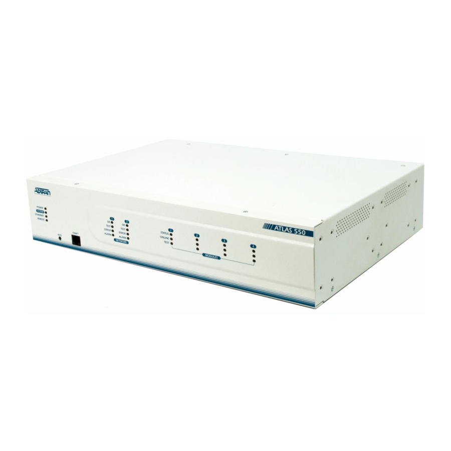
Page 28: Front Panel Leds
With the ATLAS 550 powered-up, the front panel LEDs provide visual information about the status of the ATLAS 550 and any option modules that may be installed. Table 2 provides a brief description of the front panel features, and Table 3 on page 29 provides detailed information about the LEDs. -
Page 29: Table 3. Description Of Atlas 550 Leds
ATLAS 550 System Manual Table 3. Description of ATLAS 550 LEDs For these LEDs... This color light... System Status Green Power Green (solid) Green (fast blink) Yellow (solid) System Red (solid) Red (fast blink) Green (solid) Ethernet Green (flashing) Yellow... - Page 30 Section 2 Engineering Guidelines Table 3. Description of ATLAS 550 LEDs (Continued) For these LEDs... This color light... Option Modules Status Status Green (solid) Green (fast blink) Red (solid) Red (fast blink) Red (slow blink) Online Green (solid) Green (fast blink)
-
Page 31: Reviewing The Back Panel Design
REVIEWING THE BACK PANEL DESIGN AC System The ATLAS 550 (AC System) back panel contains four slots for housing option modules which provide a variety of additional resources and data ports. All slots are functionally identical. The ATLAS 550 also contains two slots for housing network modules (see Figure 2). -
Page 32: Admin Port (Usoc Rj-48C)
(EIA-232) connects to a computer or modem (see Table 4 for the pinout) and provides the ADMIN following functions: • Accepts EIA-232 input from a PC or a modem for controlling the ATLAS 550. • Operates at 2400, 9600, 19200, or 38400 bps. •... -
Page 33: External Alarm Relay Monitor Connection
This connection alerts the user when a selected external alarm condition exists. This connection could be used to monitor a UPS with dry contacts or another ATLAS 550. The 2-pin, removable terminal block connects with external wiring. Refer to DLP-14, Connecting the Alarm Contacts, for detailed instructions. -
Page 34: Test Interface
The T1/PRI Network Interface Module ® Name Description Receive data from the network Receive data from the network ––––– Unused Transmit data toward the network Transmit data toward the network ––––– Unused © 2004 ADTRAN, Inc. ATLAS 550 System Manual 61200305L2-1B... -
Page 35: Modem Management Network Module (P/N 1200341L1), Usoc Rj-11C
ATLAS 550 System Manual Table 9. E1/PRA Network Interface 15-pin Female D-connector Pinout TXDATA-RING (R) 2,4,5,7 FRAME GROUND (FG) RXDATA-RING (R1) 6,8,10,12-15 TXDATA-TIP (T) RXDATA-TIP (T1) Test Interface This module contains two test interfaces: jacks provide intrusive test capability for the incoming E1. By connecting test equipment to these jacks, the E1 connection breaks and the test equipment terminates the incoming E1. -
Page 36: Bri Dbu Network Module (P/N 1200327L1), Usoc Rj-49C
Table 11. BRI DBU Network Module RJ-49C Pinout 1, 2, 3, 6, 7, 8 OPTION MODULE INTERFACES The ATLAS 550 contains four option slots that hold a variety of modules. This sections provides a brief description of these modules and their pinouts, as follows: •... -
Page 37: Octal/Quad Fxo Option Module (P/N 1200310L1/1200329L1), 8-Pin Modular Jack
ATLAS 550 System Manual Octal/Quad FXO Option Module (P/N 1200310L1/1200329L1), 8-Pin Modular Jack Each port of the Octal/Quad FXO Option Module has a single 8-pin modular jack. Table 13 shows the pinout. Table 13. FXO 8-Pin Modular Jack Pinout 1, 2, 3, 6, 7, 8 Dual Nx 56/64 Option Module (P/N 1200311L1), V.35 Winchester... -
Page 38: Dual Ussi Option Module (P/N 1200754L1), Db-78
Note: A signal description followed by a 1 or a 2 indicates the port on the USSI Module. Table 15. DB-78 Connector Pinout 43—48 UNUSED 62—68 UNUSED © 2004 ADTRAN, Inc. ATLAS 550 System Manual Signal Description MOD2 MOD0 EXT-TXC-A 1 DTR-B 1... -
Page 39: Table 16. Eia-530 Connector Pinout (System P/N 4200754L2)
ATLAS 550 System Manual Table 16. EIA-530 Connector Pinout (System P/N 4200754L2) Signal Description Shield (Ground) Transmit Data (A) Received Data (A) Request to Send (A) Clear to Send (A) DCE Ready (A) Signal Ground Carrier Detect (A) Received Clock (B) Carrier Detect (B) Ext. -
Page 40: Table 18. Rs-449/V.36 Connector Pinout (P/N 4200754L1)
Terminal in Service * DCE Ready (B) DTE Ready (B) Carrier Detect (B) Select Standby * Signal Quality * New Signal * Ext. Transmit Clock (B) Standby/Indicator * Send Common * © 2004 ADTRAN, Inc. ATLAS 550 System Manual 61200305L2-1B... -
Page 41: Table 19. Rs-232 Connector Pinout (P/N 4200754L4)
ATLAS 550 System Manual Table 19. RS-232 Connector Pinout (P/N 4200754L4) Signal Description Shield (Ground) Transmit Data Received Data Request to Send Clear to Send Data Set Ready Signal Ground Received Line Signal Detector + Voltage * - Voltage * Unused Sec. -
Page 42: Octal E&M Option Module (P/N 1200313L1), 8-Pin Modular Jack
VF output (4W mode, 600 Ω nominal) Trunk Circuit Connections Pin 6 Pin 6 Pin 4 Pin 6 Pin 4 Pin 6 Pin 4 Pin 6 © 2004 ADTRAN, Inc. ATLAS 550 System Manual Pin 5 Pin 5 Use Frame Ground 61200305L2-1B... -
Page 43: Dual/Quad T1/Pri Option Module (P/N 1200314L1/L2 And 1200755L1/L2), Usoc Rj-48C
ATLAS 550 System Manual Dual/Quad T1/PRI Option Module (P/N 1200314L1/L2 and 1200755L1/L2), USOC RJ-48C Each port of the Dual/Quad T1/PRI Option Module uses a single, 8-position modular jack for connection to the T1 or PRI circuit. Table 23 gives the pinout for this jack. -
Page 44: Nxt1 Hssi Option Module (P/N 1200346L1), 50-Pin Scsi-Ii
TT - Terminal Timing NxT1 HSSI/V.35 Option Module (P/N 1200346L2) V.35 is possible with the NxT1 HSSI Option Module with an appropriate adapter cable (ADTRAN P/N 3125I081@A); however, some HSSI menu options will be unavailable in this mode (for details, see the User Interface Guide section). -
Page 45: Table 28. T1 Network Connection Pinout
ATLAS 550 System Manual Table 27. HSSI/V.35 Connection Pinout (Continued) Pin# Pin# (+ side) (- side) — — 17-18 — Table 28. T1 Network Connection Pinout RXDATA-RING (R1) RXDATA-TIP (T1) TXDATA-RING (R) TXDATA-TIP (T) 3,6,7,8 ––––– 61200305L2-1B Direction Description HSSI SD - Send Data HSSI LB - Loopback Circuit B —... -
Page 46: Legacy Data Option Module (P/N 1200342L1), Eia-232 And V.35
Transmitted data (TD-B) from DTE TX clock (TC-A) to DTE TX clock (TC-B) to DTE External TX clock (ETC-A) from DTE External TX clock (ETC-B) from DTE Test mode (TM) to DTE © 2004 ADTRAN, Inc. ATLAS 550 System Manual Description 61200305L2-1B... -
Page 47: Octal Ethernet Switch Option Module (P/N 1200766L1), Usoc Rj-48C
ATLAS 550 System Manual Octal Ethernet Switch Option Module (P/N 1200766L1), USOC RJ-48C The Octal Ethernet Switch Option Module provides eight RJ-48C interfaces that can operate as 10BaseT or 100BaseTX. Table 30 gives the pinout for the Ethernet connection. 4, 5... -
Page 48: At-A-Glance Specifications
Section 2 Engineering Guidelines AT-A-GLANCE SPECIFICATIONS Table 31 lists the specifications for the ATLAS 550 system. Table 31. ATLAS 550 System Specifications Application TDM Applications TDM bandwidth Dedicated map connections Switching Applications ISDN signaling types T1 signaling types DSP Features... -
Page 49: Specification
ATLAS 550 System Manual Table 31. ATLAS 550 System Specifications (Continued) Application Frame Relay Packet throughput Management signaling interfaces Management signaling types Encapsulation PVC support Congestion control Quality of service (QOS) Testing (ADTRAN proprietary) PVC loopback SNMP support Connection support... - Page 50 Section 2 Engineering Guidelines Table 31. ATLAS 550 System Specifications (Continued) Application Voice Compression Algorithm Number of channels PCM coding Fax support Modem Support (ADPCM-32 Module only) The rates shown at the right are maximum rates. Under certain conditions, these rates may not be realized.
-
Page 51: Section 3 Network Turnup Procedure
ATLAS 550 Slot Designation (Rear Panel) ........ -
Page 52: Section 3 Network Turnup Procedure
UNPACK AND INSPECT THE SYSTEM The ATLAS 550 is shipped in its own cardboard shipping carton. Open the carton carefully and avoid deep penetration into the carton with sharp objects. After unpacking the unit, inspect it for possible shipping damage. If the equipment has been damaged in transit, immediately file a claim with the carrier, and then contact ADTRAN Customer Service (see the contact information in the front of this manual). -
Page 53: Grounding Instructions
MOUNTING OPTIONS The ATLAS 550 unit may be used on a tabletop or installed in a 19-inch or 23-inch rackmount or wallmount configuration. ADTRAN includes 19-inch rackmount ears with the ATLAS 550 shipment (23-inch rackmount ears are sold separately). For a rackmount installation, the ATLAS 550 allows flush-face mount, face-forward mount, center mount, and rear mount. - Page 54 Disconnect all four rubber feet from the bottom of the chassis. (Remove screws using a Phillips-head screwdriver.) Decide on a location for the ATLAS 550. Keep in mind that the unit needs to be mounted at or below eye-level so that the LEDs are viewable.
- Page 55 © 2004 ADTRAN, Inc. Section 3 Network Turnup Procedure Step 4: Wall mount the ATLAS 550 chassis using four #6 to #10 (1 1/2" or greater in length) wood screws.
-
Page 56: Dc-Powered Systems
The AC-powered ATLAS 550 comes equipped with a detachable 6-foot power cord with a 3-prong plug for connecting to a grounded power receptacle. As shipped, the ATLAS 550 is set to factory default conditions. To power-up the unit, ensure that the unit is properly connected to an appropriate power source and turn on the unit using the on/off switch on the back panel. -
Page 57: Instructions For Installing The Atlas 550 Network And Option Modules
Instructions for Installing the ATLAS 550 Network and Option Modules 1. Remove the cover plate from the appropriate slot of the ATLAS 550 back panel. 2. Slide the module into the slot until the module is firmly seated against the front of the chassis. -
Page 58: Bri Dbu Network Module (P/N 1200327L1)
Two T1 crossover cables (RJ-48C to RJ-48C), ADTRAN P/N 3125M010 Dual Nx 56/64 Option Module (P/N 1200311L1) Shipping Contents The ADTRAN shipment of the Dual Nx 56/64 Option Module includes the following items: • Dual Nx 56/64 Option Module •... -
Page 59: Quad Basic Rate Isdn (U-Interface) Option Module (P/N 1200315L1)
Four RJ-45-to-RJ-11 cables, ADTRAN P/N 3125M007 Quad Basic Rate ISDN (S/T Interface) Option Module (P/N 1200764L1) Shipping Contents The ADTRAN shipment of the Quad Basic Rate ISDN (S/T Interface) Option Module includes the following items: • Quad Basic Rate ISDN (S/T Interface) Option Module •... -
Page 60: Legacy Data Option Module (P/N 1200342L1)
Section 3 Network Turnup Procedure Legacy Data Option Module (P/N 1200342L1) Shipping Contents The ADTRAN shipment of the Legacy Data Option Module includes the following items: • Legacy Data Option Module • Legacy Data Option Module Quick Start Guide •... -
Page 61: Channel Voice Compression Resource Modules (P/N 1200312Lx)
• 4,8,16,24 Channel Voice Compression Resource Modules Quick Start Guide 32 Channel ADPCM Resource Module (P/N 1200752L1) Shipping Contents The ADTRAN shipment of the 32 Channel ADPCM Resource Module includes the following items: • 32 Channel ADPCM Resource Module •... - Page 62 Section 3 Network Turnup Procedure ATLAS 550 System Manual © 2004 ADTRAN, Inc. 61200305L2-1B...
-
Page 63: Provides Detailed Descriptions Of All Menu Options And Configuration Parameters Available For The Atlas
Provides detailed descriptions of all menu options and configuration parameters available for the ATLAS 550. This section of ADTRAN’s ATLAS 550 System Manual is designed for use by network administrators and others who will configure and provision the system. It contains information about navigating the VT100 user interface, configuration information, and menu descriptions. - Page 64 ATLAS 550 System Controller Self-Test Log ....... . . 95...
-
Page 65: Window Panes
Section 4 User Interface Guide NAVIGATING THE TERMINAL MENU To access the terminal menus and management features of the ATLAS 550, connect the unit to a VT100 terminal (or VT100 terminal emulator) via the interface on the front panel or the... - Page 66 More items are available when selected More items are available when selected An action is to be taken, such as activating a test You can enter data in this field The field contains read-only information © 2004 ADTRAN, Inc. ATLAS 550 System Manual 61200305L2-1B...
-
Page 67: Additional Terminal Menu Window Features
ATLAS 550 System Manual Additional Terminal Menu Window Features • SYS - displays status information about the system controller • Tool Tip - provides a brief description of the currently selected (highlighted) command • Network Status - displays status information, such as OK, WARN, or ALRM about network slots 1-2 •... -
Page 68: Session Management Keystrokes
ODULES # field in the connection list by pressing <I> EDICATED connection list by pressing EDICATED © 2004 ADTRAN, Inc. ATLAS 550 System Manual Press this key... CTRL+L CTRL+S CTRL+R CTRL+V Press this key... >... -
Page 69: Getting Help
PPP endpoints Define, configure, and monitor all ATLAS 550 Router functions Assign dedicated connections between any two ports in the ATLAS 550 D Access Dial Backup functions including monitoring the status of backup links, manually forcing a backup switch, and restoring a primary... -
Page 70: Security Levels
MENU DESCRIPTIONS The remainder of this section describes ATLAS 550 menu and submenu options. To help you follow the terminal menu hierarchy, the following notations are used: > S ENUS UBMENUS Table 1. -
Page 71: System Info
Write security: 3; Read security: 5 Provides a user-configurable text string for the location of the ATLAS 550. This field is to help you keep track of the physical location of the unit. You can enter up to 40 alphanumeric characters in this field, including spaces and special characters (such as an underbar). - Page 72 YSTEM YSTEM PTIME Read security: 5 Displays the length of time the ATLAS 550 system has been running. Each time you reset the system, this value resets to 0 days, 0 hours, 0 min and 0 secs. > S YSTEM...
-
Page 73: System Status
ATLAS 550 System Manual YSTEM TATUS menu provides the user with status information about the ATLAS 550 operational YSTEM TATUS parameters including logged system events and timing. Figure 4 displays the submenus and data fields that are available when you select this menu item. -
Page 74: Clear System Led
Write security: 3; Read security: 3 Changes the color of the SYSTEM green (OK). The LED turns red if the ATLAS 550 detects a major system failure. If the failure SYSTEM condition clears, the LED turns yellow to warn of the past failure. > E... - Page 75 ATLAS 550 System Manual > E YSTEM TATUS THERNET Read security: 5 Indicates the current status of the > E YSTEM TATUS THERNET Read security: 5 Indicates the number of frames transmitted from the > E YSTEM TATUS THERNET Read security: 5 Indicates the number of frames received on the >...
- Page 76 Indicates which timing source (primary or backup) is currently being used by ATLAS 550 and whether the system is locked onto this source. If the display does not indicate locked, the ATLAS 550 does not have a valid source of timing and cannot reliably transfer data. Review the current setting for system timing source in the menu.
- Page 77 ATLAS 550 System Manual > R YSTEM TATUS ESOURCE Read security: 5 Displays types of dynamically allocated resources being tracked throughout the system. Examples are (analog modem resource), NALOG compression resource). > R YSTEM TATUS ESOURCE Read security: 5 Shows the number of resources available (not in use) and the total number of resources. If a resource is taken offline, it is not included in the total.
- Page 78 > D > A SAGE ABLES VERAGE > D > M SAGE ABLES > D > 0 (Z SAGE ABLES © 2004 ADTRAN, Inc. ATLAS 550 System Manual ETWORK (Primary Rate ISDN circuits (T1/RBS trunks configured as (T1/RBS ETWORK VAIL 61200305L2-1B...
- Page 79 ATLAS 550 System Manual > T YSTEM TATUS RUNK Read security: 5 Displays the usage data broken down by slots and ports. > T YSTEM TATUS RUNK Write security: 4; Read security: 5 Activates the reset of all accumulated availability statistics.
-
Page 80: System Config
Please refer to the specific module information to determine if a port can provide timing for the system. The ATLAS 550 uses the backup timing source if the primary timing source goes into alarm. The ACKUP for the most reliable operation. - Page 81 (four decimal numbers, each in the range of 0 to 255, separated by periods). This value is set to 255.255.255.0 by default. This part of the destination IP address is used along with the ATLAS 550 IP address to determine which nodes must be reached through the default IP gateway.
- Page 82 10 or 100 Mbps. > E YSTEM ONFIG THERNET Read security: 5 Displays the current status of the DHCP client in the ATLAS 550. The following states are possible (per RFC 2131): ELECTING EQUESTING > E YSTEM ONFIG...
- Page 83 ARDWARE > SNMP YSTEM ONFIG Write security: 3; Read security: 5 Provides a way to configure SNMP access for the ATLAS 550. The following options are available for review and editing: > SNMP > SNMP A YSTEM ONFIG Write security: 3; Read security: 5 Defines whether SNMP access to the ATLAS 550 is for your application.
- Page 84 YSTEM ONFIG Write security: 3; Read security: 5 Enables and disables the authentication failure trap. The authentication failure trap is sent (when each time authenticated access to the ATLAS 550 fails. > SNMP > T YSTEM ONFIG Write security: 3; Read security: 5 Defines the destination for SNMP traps as follows: >...
- Page 85 Defines performance threshold values for DS1 Line and Path statistics recorded in a 15-minute interval. Refer to the ADTRAN Enterprise MIB and the DS1 Extension MIB (These MIB listings are available on the documentation CD or the ADTRAN website at Click Service/Support >Technical Support >...
- Page 86 ONFIG Write security: 3; Read security: 5 Defines performance threshold values for DS1 Line and Path statistics. Refer to the ADTRAN Enterprise MIB and DS1 Extension MIB (available on the ADTRAN website at www.adtran.com) for more MIB specific information. If a statistic value exceeds its threshold value, then the corresponding Alert Trap will be sent if the Alert Event is armed and Alert Traps are enabled.
- Page 87 Write security: 0; Read security: 0 Configures the ADLP list used when accepting incoming traps from remote ADTRAN TSU 100 Series or ISU 512 units. For a trap to be recognized and sent to the network management station (NMS) listed in the...
- Page 88 Write security: 0; Read security: 0 Enables or disables trap polling through the ATLAS 550 to remote ADTRAN TSU 100 Series or ISU 512 units. When enabled, this feature allows the ATLAS 550 to forward any traps received from remote units...
- Page 89 Specifies the facility destination of log events. Facilities are located on the host and are managed by the Syslog host daemon running on either a UNIX machine or a PC. For details on the ADTRAN syslog server host facilities, please refer to Section 8, ADTRAN Utilities.
- Page 90 > L YSTEM ONFIG ICENSES Write security: 0; Read security: 0 (Not currently used.) Provides menus to enable the optional ATLAS 550 feature upgrades. Names the ATLAS 550 feature upgrade. EATURE Displays the license key of the feature upgrade. ICENSE Displays the serial number of the feature upgrade.
- Page 91 > A YSTEM ONFIG LARM Write security: 3; Read security: 5 Clears the Alarm Relay located on the back panel of the ATLAS 550. Activating the software Alarm Relay Reset functions the same as manually pressing the > A YSTEM ONFIG LARM Write security: 3;...
-
Page 92: System Utility
PDATE Write security: 1; Read security: 5 Updates firmware when ATLAS 550 enhancements are released. Two transfer methods are available for use in updating any modules that contain Flash memory—including the ATLAS 550 system controller. The first transfer method uses the ATLAS 550 serial protocol. - Page 93 Write security: 1; Read security: 5 (Available for TFTP transfers only.) Configures the IP address of the TFTP Server on which the update file resides. The ATLAS 550 uses this field to locate the network server on which the update file resides. > U...
- Page 94 ONFIG Write security: 3; Read security: 5 Allows configuration files to be saved and shared among ATLAS 550 units. Two transfer methods are available for use when transferring configuration files to or from the unit. The first transfer method uses...
- Page 95 ATLAS 550 System Manual To support these TFTP transfers, ADTRAN delivers a TFTP Server (as part of ADTRAN Utilities) on the ATLAS 550 documentation CD. You can install the ADTRAN Utilities software on any PC running Microsoft Windows, and use the TFTP server for TFTP transfers to/from the ATLAS 550.
- Page 96 DDRESS > S YSTEM TILITY YSTEM Write security: 0; Read security: 0 Displays statistics related to the ATLAS 550 internal operating system. Please check with ADTRAN Technical Support before attempting to use this menu. > S YSTEM TILITY YSTEM Write security: 3; Read security: 5 Initiates a system self-test.
- Page 97 ATLAS 550 port number. Event description. VENT Show P ESULT The tests associated with the system controller are shown in Table 2. Table 2. ATLAS 550 System Controller Self-Test Log HIS EVENT OGS THIS RESULT Flash Flash memory checksum verified BootRom...
- Page 98 Read security: 5 Displays the average round trip time of the ping request/reply of the current set of pings. > C ELFTEST LEAR ELFTEST DDRESS OUNT YTES IMEOUT OUND OUND © 2004 ADTRAN, Inc. ATLAS 550 System Manual interface. ETHERNET 61200305L2-1B...
- Page 99 Write security: 5; Read security: 5 Allows a user to remotely configure ADTRAN TSUs using ADLP over the inband management channel on a V.35 port. This feature only allows for remote sessions through the ATLAS 550 to the TSUs – not vice versa.
- Page 100 TILITY EBOOT Write security: 0; Read security: 0 Reboots the ATLAS 550 system. When you select this command, the following message displays: ** WARNING ** This will reboot the entire system and service will be interrupted! Press to reboot the system or >...
-
Page 101: Modules
Resets the entire system to the factory default settings. To reset the system, press command, press . When you select this command, the following message displays: This will delete all configuration settings. ADTRAN recommends making a backup copy of the configuration before defaulting the system. ODULES Write security: 3;... - Page 102 Read security: 5 Identifies the slot number. Slot 0 refers to the ATLAS 550 Base Unit. The ATLAS 550 has three types of slots: network slots, option module slots, and resource module slots. The two network slots are designated through , and the four resource module slots are designated installed onto any option module, but not onto network modules.
-
Page 103: Modules Menu (E1/Pra Network Interface Module)
ODULES TATE Read security: 5 Displays whether the ATLAS 550 controller or selected module is online or offline. Even though a module is physically installed, it must be marked parameter allows an installed module to be marked troubleshooting. If you choose . - Page 104 LARM Read security: 5 Displays an alarm condition on the ATLAS 550 unit. Press <Enter> to access this menu item. Indicates a loss of signal detected on port interface. Indicates inability to frame data received on the port. Alternately referred to as Out of Frame (OOF).
- Page 105 ATLAS 550 System Manual (T1/PRI-1) > DS0 S ODULES Read security: 5 The DS0 status indicates usage on a DS0 basis. These options are read-only: Unallocated Inactive Signaling mismatch Active B Channel Active D Channel Maintenance Dedicated (nailed) Off hook - originate (RBS) Ringing (RBS);...
- Page 106 All of the following configurable parameters apply to whether the port is connected to a Primary Rate ISDN circuit or a channelized T1 circuit. (T1/PRI-1) > C ODULES ONFIGURATION Read security: 5 Displays the port number. > P © 2004 ADTRAN, Inc. ATLAS 550 System Manual 61200305L2-1B...
- Page 107 Write security: 2; Read security: 5 Selects the Line Build Out (LBO) for the network interface. When connecting an ATLAS 550 port to a DSX-1 interface, this parameter is typically set to match the distance (in feet) between the ATLAS 550 and the device with which it is connecting.
- Page 108 ODULES ONFIGURATION Write security: ADTRAN Use Only; Read security: 5 The ADTRAN Data Link Protocol (ADLP) provides a communications link between ADTRAN equipment over point-to-point or multidrop connections that can be used for configuring and monitoring remote ADTRAN devices. Choose (T1/PRI-1) >...
- Page 109 ATLAS 550 System Manual (T1/PRI-1) > T ODULES Write security: 4; Read security: 5 Sends loopback code to remote CSU. The following options are available: Selection Framing AT&T I ESF/D4 NBAND LINE ANSI FDL L ANSI FDL P ESF/D4 NBAND (T1/PRI-1) >...
-
Page 110: Modules Menu (Modem Management Network Module)
ODULES This section provides detailed information on the Interface Module. The ATLAS 550 system controller automatically detects the presence of the E1/PRA Network Interface Module when it is installed in the system (listed as E1/PRA Network Interface Module via the terminal menu, use the arrow keys to scroll to the menu and press <Enter>... - Page 111 (E1/PRA-1) > S ODULES Read security: 5 Displays the state of the A/B/C/D signaling bits for the E1/PRA Network Interface Module. Dashes indicate TS0s where signaling is not being transferred by the ATLAS 550. 61200305L2-1B LARMS TATUS Dedicated (nailed) TS0...
- Page 112 Write security: 5; Read security: 5 All of the following configurable parameters apply whether the port is connected to a Primary Rate Access circuit or a channelized E1 circuit. URRENT © 2004 ADTRAN, Inc. ATLAS 550 System Manual or greater 61200305L2-1B...
- Page 113 ATLAS 550 System Manual (E1/PRA-1) > C ODULES ONFIGURATION Write security: 3; Read security: 5 Displays the port number. (E1/PRA-1) > C ODULES ONFIGURATION Write security: 3; Read security: 5 Accepts any alpha-numeric name up to 16 characters long, to uniquely identify the E1/PRA port.
- Page 114 Figure 10. E1/PRA Network Loopback Test Diagram > TS16 S PARE > I > L UILD Ω ( ALANCED > P > L E1/PRA Line Loopback © 2004 ADTRAN, Inc. ATLAS 550 System Manual Ω ( ) or NBALANCED ALANCED 61200305L2-1B...
-
Page 115: Modules Menu (Bri Dbu Network Interface Module)
ODULES ODEM The ATLAS 550 system controller automatically detects the presence of the Modem Management Network Module when it is installed in the system (listed as Modem Management Network Module via the terminal menu, use the arrow keys to scroll to the menu and press <Enter>... - Page 116 TATUS YTES > R TATUS YTES > O TATUS VERRUN > F TATUS RAMING > C TATUS LEAR OUNTERS > H TATUS ANGUP ODEM > C TATUS ONNECT © 2004 ADTRAN, Inc. ATLAS 550 System Manual (Clear To Send), 61200305L2-1B...
-
Page 117: Modules Menu (Dual/Quad T1/Pri Option Modules)
(BRI DBU N ODULES The ATLAS 550 system controller automatically detects the presence of the BRI DBU Network Interface Module when it is installed in the system (listed as Interface Module via the terminal menu, use the arrow keys to scroll to the <Enter>... - Page 118 A single channel is connected and negotiating the BONDING call for a EGOTIATING particular BONDING session. The initial BONDING negotiation was successful, and the ATLAS 550 is in HANNELS the process of adding channels to the BONDING session. BONDING The remaining channels were brought up successfully, and the BONDING session is now ready to pass data.
- Page 119 ATLAS 550 System Manual ) > B ODULES ONDING Read security: 5 Displays the number of bearer channels used in this BONDING session. When the number is displayed in the format X/Y, Y is the number of BONDING resources reserved for this session, and X is the number of calls belonging to this session that are up.
- Page 120 Read security: 5 Indicates the port number. > TANULL T ONFIGURATION > TCID T ONFIGURATION IMER > C ONFIGURATION TAGGER , and TAGGER > P HYSICAL LARM TATUS > P TATUS © 2004 ADTRAN, Inc. ATLAS 550 System Manual IMER 61200305L2-1B...
- Page 121 ATLAS 550 System Manual ) > B ODULES HANNEL Read security: 5 (Channel) Displays the status of individual channels. The following symbols may display: Unallocated channel Inactive channel Active B channel Active D channel ) > P ODULES ERFORMANCE Write security: 3; Read security: 5 The performance field provides status on key performance measures for the BRI interface.
-
Page 122: Modules Menu (Dual Nx56/64 Option Module)
OOPBACK ODULES This section provides detailed information on the Option Modules. The ATLAS 550 system controller automatically detects the presence of the Dual/Quad T1/PRI Option Modules when they are installed in the system (Dual is listed as listed as ). All menus detailed in this section that apply to both modules are listed as... - Page 123 LARM Read security: 5 Displays an alarm condition on the ATLAS 550 unit. Press <Enter> to access this menu item. Indicates a loss of signal detected on port interface. Indicates inability to frame data received on the port. Alternately referred to as Out of Frame (OOF).
- Page 124 Read-only field that indicates signaling of all 24 DS0s. The A/B bits for Rx (receive) and Tx (transmit) DS0s are shown. Dashes display for those DS0s where robbed bit signaling (RBS) is not being transferred by the ATLAS 550. (T1/PRI-2/4) > P...
- Page 125 ATLAS 550 System Manual Path Code Violation is a received error in the frame synchronization bit (for SF framing) or a CRC error (ESF framing). Line Errored Second is a second in which an error was received on the T1.
- Page 126 Write security: 2; Read security: 5 Selects the Line Build Out (LBO) for the network interface. When connecting an ATLAS 550 port to a DSX-1 interface, this parameter is typically set to match the distance (in feet) between the ATLAS 550 and the device with which it is connecting.
- Page 127 ATLAS 550 System Manual Figure 11. T1/PRI Loopback Test Diagram (T1/PRI-2/4) > T ODULES Write security: 4; Read security: 5 Sends loopback code to remote CSU. The following options are available: Selection Framing AT&T I ESF/D4 NBAND LINE ANSI FDL L...
-
Page 128: Modules Menu (Dual Ussi Option Module)
Injects errors into transmitted test pattern. ODULES The ATLAS 550 system controller automatically detects the presence of the Dual Nx 56/64 Option Module when it is installed in the system (listed as Module via the terminal menu, use the arrow keys to scroll to the access the module choices. - Page 129 ODULES LARM Read security: 5 Displays an alarm condition on the ATLAS 550 unit. A rate mismatch exists between the DTE clock and the network-side clock (as set by DS0 assignment). The Nx port is not able to lock onto the clock provided by the network interface.
- Page 130 Displays the Phase Lock Loop (PLL) and FIFO status. > P > R TATS > P TATS > R TATS RAMES > T TATS RAMES > R TATS YTES > T TATS YTES > R TATS ESET TATS © 2004 ADTRAN, Inc. ATLAS 550 System Manual 61200305L2-1B...
- Page 131 ONFIGURATION Write security: 3; Read security: 5 Controls the clock used by the ATLAS 550 to accept the transmit (TX) data from the DTE. This is usually set to . If the interface cable is long, causing a phase shift in the data, the clock can be set to ORMAL .
- Page 132 Creates an inband management channel by robbing 8 kbps bandwidth from the port’s allocated bandwidth. This channel can be used for management for ADTRAN products that are not co-located with the ATLAS. Consult the manual for ADTRAN T1 equipment for details on using this feature.
- Page 133 ATLAS 550 System Manual (V35N -2) > C ODULES ONFIGURATION Write security: 3; Read security: 5 Sends the state of the DTE leads to the remote unit whenever any of the leads change state. If any leads on the remote unit are set to track a remote signal, this option must be enabled. The DTE lead states are conveyed using the Inband control channel, which must be enabled.
- Page 134 Number of seconds with at least one bit error. > P > L OOPBACK > L OOPBACK TATUS EMOTE AILED OOPED OOPBACK CTIVE > 511 > 511 R ESULT © 2004 ADTRAN, Inc. ATLAS 550 System Manual EMOTE OURCE 61200305L2-1B...
-
Page 135: Modules Menu (Quad/Octal Fxs Option Module)
Clears error counters on test pattern results menu. ODULES The ATLAS 550 system controller automatically detects the presence of the Dual USSI Option Module when it is installed in the system (listed as via the terminal menu, use the arrow keys to scroll to the module choices. - Page 136 ODULES LARM Read security: 5 Displays an alarm condition on the ATLAS 550 unit. A rate mismatch exists between the DTE clock and the network-side clock (as set by DS0 assignment). The USSI port is not able to lock onto the clock provided by the network interface.
- Page 137 ATLAS 550 System Manual (USSI-2) > D ODULES Read security: 5 Displays operating port. There are 2 available interfaces on the Dual USSI Option Module. (USSI-2) > D ODULES Read security: 5 Displays the data rate of the selected port.
- Page 138 ONFIGURATION Write security: 3; Read security: 5 Controls the clock used by the ATLAS 550 to accept the transmit (TX) data from the DTE. This is usually set to . If the interface cable is long, causing a phase shift in the data, the clock can be set to ORMAL .
- Page 139 Creates an inband management channel by robbing 8 kbps bandwidth from the port’s allocated bandwidth. This channel can be used for management for ADTRAN products that are not co-located with the ATLAS. Consult the manual for ADTRAN T1 equipment for details on using this feature.
- Page 140 These options initiate different types of tests and display test results. (USSI-2) > T ODULES Write security: 5; Read security: 5 Displays the port number. UMBER > P © 2004 ADTRAN, Inc. ATLAS 550 System Manual NTERFACE section of NTERFACE ONFIGURATION 61200305L2-1B...
- Page 141 ATLAS 550 System Manual (USSI-2) > T ODULES Write security: 4; Read security: 5 Test pattern to be transmitted out the port. The following options are available: No active loopback. OOPBACK Activates both a local loopback (back toward the DTE) and a port...
- Page 142 Displays the current configuration of the Dual USSI Module DTE Interface. ODULES The ATLAS 550 system controller automatically detects the presence of the Quad BRI (U Interface) Option Module when it is installed in the system (listed as (U Interface) Option Module via the terminal menu, use the arrow keys to scroll to the press <Enter>...
- Page 143 ATLAS 550 System Manual (U-BRI-4) > I ODULES Read security: 5 Provides information about the module part number, serial number, and assembly revision. (U-BRI-4) > I ODULES Read security: 5 Displays the part number of the module. (U-BRI-4) > I...
- Page 144 Write security: 5; Read security: 5 Displays the port number. There are 4 available interfaces on the Quad BRI-U Option Module. > C TATUS URRENT > P > P > P © 2004 ADTRAN, Inc. ATLAS 550 System Manual 61200305L2-1B...
- Page 145 ATLAS 550 System Manual (U-BRI-4) > T ODULES Write security: 4; Read security: 5 Activates a local loopback of the U interface toward the network. The following options are available: OOPBACK OOPBACK B1 & B2 OOPBACK 2B+D OOPBACK ODULES The ATLAS 5500 system controller automatically detects the presence of the Quad BRI (S/T Interface)
- Page 146 Accepts any alpha-numeric name up to 16 characters long, to uniquely identify each port on the Octal BRI S/T Option Module. > A LARMS > C HANNEL SAGE > P SAGE > C SAGE > P > P © 2004 ADTRAN, Inc. ATLAS 550 System Manual ) indicates – 61200305L2-1B...
- Page 147 ONFIGURATION Write security: 3; Read security: 5 The ATLAS 550 is capable of providing 1W (at 40 V) power on each BRI S/T interface to provide line power (phantom power) to TE equipment. Set this parameter to the S/T interface requires line power.
-
Page 148: Modules Menu (Quad /Octal Fxs Option Module )
Section 4 User Interface Guide ODULES The ATLAS 550 system controller automatically detects the presence of the Quad/Octal FXS Option Modules when they are installed in the system (Quad is listed as All menus in this section that apply to both modules are listed as Quad/Octal FXS Option Module via the terminal menu, use the arrow keys to scroll to the and press <Enter>... - Page 149 Ringing test is currently running, but an off hook condition is detected. (FXS-4/8) > S ODULES TATUS Read security: 5 Receive Signaling bits have local significance only, and represent signaling between the ATLAS 550 Controller and the voice port if the port is configured in the (FXS-4/8) > S ODULES TATUS...
- Page 150 Write security: 3; Read security: 5 Sends a 1kHz tone into the following locations, based on test selection: port, while sends the tone into the digital PCM stream of the ATLAS 550 controller. These tests are useful for verifying a voice path. > P >...
- Page 151 ATLAS 550 System Manual (FXS-4/8) > T ODULES Write security: 3; Read security: 5 Activates loopback tests on a per-port basis. Normal operation. Loops the 2W test on itself. NALOG Loops digital data entering the FXS from the ATLAS controller on itself.
-
Page 152: Modules Menu (Quad /Octal Fxo Option Module )
Displays the current PCM coding scheme. Currently only ODULES The ATLAS 550 system controller automatically detects the presence of the Octal/Quad FXO Option Module when they are installed in the system (Quad is listed as All menus in this section that apply to both modules are listed as Octal/Quad FXO Option Module via the terminal menu, use the arrow keys to scroll to the and press <Enter>... - Page 153 OLLED (FXO-4/8) > S ODULES TATUS Read security: 5 Receive Signaling bits have local significance only, and represent signaling between the ATLAS 550 Controller and the voice port if the port is configured in the 61200305L2-1B > P > S...
- Page 154 Write security: 3; Read security: 5 Sends a 1kHz tone into the following locations, based on test selection: FXO port, while sends the tone into the digital PCM stream of the ATLAS 550 controller. These tests are useful for verifying a voice path. > T ABCD >...
- Page 155 ATLAS 550 System Manual (FXO-4/8) > T ODULES Write security: 3; Read security: 5 Activates loopback tests on a per-port basis. Normal operation. Loops the 2W test on itself. NALOG Loops digital data entering the FXO from the ATLAS controller on itself.
- Page 156 Displays the current PCM coding scheme. Currently only ODULES CTAL The ATLAS 550 system controller automatically detects the presence of the Octal E&M Option Module when it is installed in the system (listed as via the terminal menu, use the arrow keys to scroll to the module choices.
- Page 157 NKNOWN (E&M-8) > S ODULES TATUS Read security: 5 Receive Signaling bits have local significance only, and represent signaling between the ATLAS 550 Controller and the voice port if the port is configured in the (E&M-8) > S ODULES TATUS...
- Page 158 Sends a 1kHz tone into the following locations, based on test selection: VF port, while sends the tone into the digital PCM stream of the ATLAS 550 controller. These tests are useful for verifying a voice path. (E&M-8) > T >...
- Page 159 ATLAS 550 System Manual (E&M-8) > C ODULES ONFIG Read security: 5 Displays the port number. (E&M-8) > C ODULES ONFIG Write security: 3; Read security: 5 Accepts any alpha-numeric name up to 16 characters long, to uniquely identify each port on the Octal E&M Option Module.
- Page 160 Section 4 User Interface Guide ODULES EGACY The ATLAS 550 system controller automatically detects the presence of the Legacy Data Option Module when they are installed in the system (listed as Module via the terminal menu, use the arrow keys to scroll to the access the module choices.
- Page 161 ATLAS 550 System Manual -4) > P ODULES EGACY Write security: 5; Read security: 5 Shows statistics for each port of the Legacy Data Option Module including a frame count of transmitted and received frames, errors, and async/sync statistics. -4) > P...
- Page 162 Enabling this test will disrupt data flow on the selected port. T1 HSSI ODULES The ATLAS 550 system controller automatically detects the presence of the NxT1 HSSI and NxT1 HSSI/V.35 Option Modules when they are installed in the system (NxT1 HSSI listed as NxT1 HSSI/V.35 listed as HSSV35 HSSI and NxT1 HSSI/V.35 Option Modules unless otherwise specified.To see the menus for the NxT1...
- Page 163 ATLAS 550 System Manual T1 HSSI) > I ODULES Read security: 5 Displays the serial number of the module. T1 HSSI) > I ODULES Read security: 5 Displays the assembly revision of the installed module. T1 HSSI) > I ODULES Read security: 5 Displays the firmware revision of the installed module.
- Page 164 Write security: 3; Read security: 5 All of the following configurable parameters apply to whether the port is connected to a Primary Rate ISDN circuit or a channelized T1 circuit. URRENT © 2004 ADTRAN, Inc. ATLAS 550 System Manual 61200305L2-1B...
- Page 165 Write security: 2; Read security: 5 Selects the Line Build Out (LBO) for the network interface. When connecting an ATLAS 550 port to a DSX-1 interface, this parameter is typically set to match the distance (in feet) between the ATLAS 550 and the device with which it is connecting.
- Page 166 The T1 data stream is not mapped to the HSSI interface. NACTIVE > L T1/PRI NI CSU Payload Loopback Line Loopback ENUS > S ENUS TATUS > S > P ENUS TATUS > S > L ENUS TATUS © 2004 ADTRAN, Inc. ATLAS 550 System Manual EDICATED 61200305L2-1B...
- Page 167 ODULES Enabling the option configures the NxT1 HSSI Module to prevent ones density violations when CRAMBLE transmitting ADTRAN IMUX headers on a T1 circuit with AMI line coding. Use extreme caution when disabling the enabling the CRAMBLE T1HSSI) > HSSI M...
- Page 168 A remote line loopback occurs at the T1 interface and is used to test functionality between the DTE and the T1 interfaces. Local Line Loopback NxT1 HSSI IMUX > S > CA ENUS TATUS © 2004 ADTRAN, Inc. ATLAS 550 System Manual Local DTE Loopback 61200305L2-1B...
- Page 169 ATLAS 550 System Manual T1HSSI) > HSSI M ODULES Read security: 5 Displays the status of the loopback circuit A and B signals. LA and LB are asserted by the DTE to enable a loopback on the DCE and its associated data communications channel. There are four loopback options: T1HSSI) >...
- Page 170 , DSR will generally be asserted when the interface is ORMAL , DSR will always be asserted. If set to ORCED > C > I ENUS ONFIG ORCED © 2004 ADTRAN, Inc. ATLAS 550 System Manual , the value EMOTE EACT (data (Data Carrier 61200305L2-1B...
- Page 171 ATLAS 550 System Manual T1HSSI) > HSSI M ODULES Write security: 5; Read security: 5 (Available only on the NxT1 HSSI/V.35 Option Module - P/N 1200346L2.) Determines the behavior of the Data Carrier Detect (DCD) signal (also called RLSD on some interfaces). If se tot Normal, DCD will generally be asserted when the interface is capable of passing data.
-
Page 172: Modules Menu (Quad/Octal Fxo Option Module)
DCE equipment. ODULES THERNET The ATLAS 550 system controller automatically detects the presence of the Ethernet Switch Module when it is installed in the system (listed as terminal menu, use the arrow keys to scroll to the choices. -
Page 173: Modules Menu (Octal E&M Option Module)
Module are capable of 10BaseT (listed as ODULES ESOURCE The ATLAS 550 system controller automatically detects the presence of the Resource Host Module when it is installed in the system (listed as terminal menu, use the arrow keys to scroll to the choices. - Page 174 (VCOM- ) > S ODULES TATUS Read security: 5 Indicates the resource number of the packet voice device listed. On the ATLAS 550, packet voice devices are numbered 1-24. PTION ODULE VCOM- for 1200312L4). To see the menus for the VCOM Resource >...
- Page 175 Denotes the voice compression algorithm being used by the packet voice device. Any packet voice device can use any available compression algorithm. When ATLAS 550 chooses a packet voice device for a particular call, the voice compression algorithm is set to match the dial plan endpoint configuration. Refer to the Frame Relay menu section of this manual for more information.
- Page 176 2100 HZ tone. After completing the 2100 Hz, both FAX endpoints repeat a V.21 cycle for each page of the FAX document. Each packet the ATLAS 550 receives from its connected frame relay endpoint is classified into one of the following groups:...
- Page 177 ATLAS 550 System Manual (VCOM- ) > C ODULES ONFIG Read security: 5 Indicates the resource number of the packet voice device listed. On the ATLAS 550, packet voice devices are numbered 1-24. (VCOM- ) > C ODULES ONFIG Write security: 4; Read security: 5 Controls the configuration state of the individual packet voice device.
- Page 178 These options initiate different types of tests and display test results. (VCOM- ) > S ODULES TATISTICS Read security: 5 Indicates the resource number of the packet voice device listed. On the ATLAS 550, packet voice devices are numbered 1-24. (VCOM- ) > S ODULES TATISTICS...
- Page 179 TATISTICS Read security: 5 Counts every frame successfully sent to or received from the ATLAS 550 system controller. This is an indication of activity but does not indicate the actual amount of packet data exchanged. The following equation gives the total number of frames handled for this packet voice device by the ATLAS 550:...
- Page 180 Displays the status of each of the packet voice resources. (ADPCM-32) > S ODULES Read security: 5 Indicates the resource number of the packet voice device listed. On the ATLAS 550, packet voice devices are numbered 1-24. ADPCM R ESOURCE ADPCM-32 >...
- Page 181 The codec for an individual call is selected when the connection is configured. When ATLAS 550 assigns a packet voice device to a particular call, the that packet voice devise is switched to the proper codec. Refer to the Frame Relay menu section of this manual for more information.
- Page 182 Section 4 User Interface Guide (ADPCM-32) > C ODULES Read security: 5 Indicates the resource number of the packet voice device listed. On the ATLAS 550, packet voice devices are numbered 1-24. (ADPCM-32) > C ODULES Write security: 3; Read security: 5 Controls the configuration state of the individual packet voice device.
- Page 183 ODULES Read security: 5 (ATLAS Frames) Counts every frame that the ATLAS 550 sends to or receives from the packet voice device. This count indicates activity but does not indicate the actual amount of frame relay data exchanged. The total number of frames handled by the packet voice device is given by the following equation:...
- Page 184 56/64 BOND ODULES The ATLAS 550 system controller automatically detects the presence of the Nx 56/64 BONDing Resource Module when it is installed in the system (listed as BONDing Resource Module via the terminal menu, use the arrow keys to scroll to the press <Enter>...
- Page 185 A single channel is connected and negotiating the BONDING call for a EGOTIATING particular BONDING session. The initial BONDING negotiation was successful, and the ATLAS 550 is in HANNELS the process of adding channels to the BONDING session. BONDING The remaining channels were brought up successfully, and the BONDING session is now ready to pass data.
- Page 186 BONDING call has failed. > TXINIT T IMER > TXFA T IMER > TXADD01 T IMER > TXDEQ T IMER > TANULL T IMER > TCID T IMER © 2004 ADTRAN, Inc. ATLAS 550 System Manual TXADD01 61200305L2-1B...
-
Page 187: Packet Manager
ATLAS 550 System Manual (BONDING) > C ODULES ONFIGURATION Write security: 3; Read security: 5 Specifies the amount of delay between placing calls for outgoing BONDING sessions. The following call stagger values are available: There is no delay between the call dialing of a BONDING session. - Page 188 NDPNTS > S > P NDPNTS TATUS ROTOCOL indicates this packet endpoint is configured for > S > S NDPNTS TATUS > S > S NDPNTS TATUS © 2004 ADTRAN, Inc. ATLAS 550 System Manual menu. ONFIG indicates SDLC 61200305L2-1B...
- Page 189 ATLAS 550 System Manual > P ACKET ANAGER ACKET Read security: 5 (Valid only for Frame Relay endpoints.) Indicates the frame relay signaling state on this packet endpoint. The possible states are defined below. > P ACKET ANAGER ACKET Read security: 5 (Valid only for PPP endpoints.) Indicates the status of the PPP negotiation.The possible states are defined...
- Page 190 ERFORMANCE indicates this packet endpoint is configured for > P > L NDPNTS ERFORMANCE in the ACKET NDPTS ONFIG © 2004 ADTRAN, Inc. ATLAS 550 System Manual NDPNT menu (see also Packet ONFIG indicates SDLC TATS RAME ELAY menu. 61200305L2-1B...
- Page 191 ATLAS 550 System Manual Number of link integrity polls transmitted by this packet endpoint. NTEGRITY TATUS Number of link integrity polls received by this packet endpoint. NTEGRITY TATUS Clears all values in this submenu. LEAR OUNTERS > P ACKET ANAGER ACKET Write security: 3;...
- Page 192 Total number of frame relay user data packets transmitted over this PVC. CKTS Write security: 3; Read security: 5 Total number of frame relay user data packets received over this PVC. > P > S NDPNTS ERFORMANCE © 2004 ADTRAN, Inc. ATLAS 550 System Manual UBLINK TATS RAME ELAY 61200305L2-1B...
- Page 193 ATLAS 550 System Manual TATISTICS Write security: 3; Read security: 5 Provides additional information, as follows, on the individual sublink: ESET OUNTERS Write security: 3; Read security: 5 Resets all sublink counters. FECN C OUNT Write security: 3; Read security: 5 Total number of FECN bits received on this PVC.
- Page 194 ONFIG configures this packet endpoint for frame relay RAME ELAY configures this packet endpoint as an SDLC endpoint. SDLC > C > C NDPNTS ONFIG ONFIG © 2004 ADTRAN, Inc. ATLAS 550 System Manual configures this packet RAME ELAY 61200305L2-1B...
- Page 195 ATLAS 550 System Manual (N391) OLLS TATUS Write security: 3; Read security: 5 Controls how many link integrity polls occur between full status polls. VENT HRESHOLD Write security: 3; Read security: 5 Sets the number of bad polling events that will cause the link to be declared down in N393 polls.
- Page 196 SERNAME Write security: 3; Read security: 5 The username that the peer will use to authenticate the ATLAS 550. ASSWORD Write security: 3; Read security: 5 The password that the peer will use to authenticate the ATLAS 550.
- Page 197 ATLAS 550 System Manual LCP D EBUGGING Write security: 3; Read security: 5 This turns on LCP negotiation debugging. IPCP D EBUGGING Write security: 3; Read security: 5 This turns on IPCP negotiation debugging. BCP D EBUGGING Write security: 3; Read security: 5 This turns on BCP negotiation debugging.
- Page 198 The number entered sets the ration. When a remote unit is polled repeatedly and no answer is received, the ATLAS 550 will move the unit from the normal poll interval to the slow poll interval. If 5 is entered here, the remote units on the slow poll will only get polled after the responsive units have been polled 5 times.
-
Page 199: Data Format
ATLAS 550 System Manual CTS O PTION Write security: 3; Read security: 5 Configures the Clear To Send (CTS) signal on this interface. CTS may be forced on or can be configured to be asserted only when Request To Send (RTS) is asserted. -
Page 200: Diagnostic Mode
A good value is R/300, where R is the smallest of the ATLAS 550 link rates or the far end link rate in bits per second. For example, if a DLCI comes from an FSU 5622 running on a 56K DDS line and is delivered to the ATLAS 550 on a full T1, the lower rate is 56000 and the value is 186 or 187. - Page 201 ATLAS 550 System Manual RIMARY ACKUP ELECTION Write security: 3; Read security: 5 Allows you to define a sublink as a primary or a backup sublink. sublink and includes the menus defines a backup sublink and includes the menus UBLINK...
-
Page 202: Backup Mode
Provides normal operation. Forces a switch to backup. Disables backup switching. to switch to backup if LMI signaling is © 2004 ADTRAN, Inc. ATLAS 550 System Manual to switch to backup if the primary to switch to backup if the 61200305L2-1B... - Page 203 ATLAS 550 System Manual > P ACKET ANAGER ACKET Read security: 5 This field displays a 7-character summary of the references to this link. Each position is populated with a dash (-) or a character indicating the resource represented. The characters are as follows:...
- Page 204 IAGNOSTIC is not running and the DLCI is configured for continuous in-band delay menu accumulates these measurements. ESULTS is running. The following URATION © 2004 ADTRAN, Inc. ATLAS 550 System Manual BAND ELAY field shows the time remaining in 61200305L2-1B...
- Page 205 ROPPED Read security: 5 Displays the total number of packets lost in the receiving direction (traveling from the remote ADTRAN frame relay device to the ATLAS). ROPPED Read security: 5 Displays the total number of packets lost in the transmit direction (traveling from the ATLAS to the remote ADTRAN frame relay device).
- Page 206 Selects one packet endpoint for the packet connection. Packet endpoints created in the packet endpoint configuration are visible on a pull-down menu which includes the internal ATLAS 550 router and can be used multiple times within the > P ACKET...
- Page 207 RAME Write security: 2; Read security: 5 Identifies the PVC to be polled. Indicates the number of sublinks that ATLAS 550 will collect IQ data for within the given link. Displays the user-designated name of the sublink (up to 15 characters).
- Page 208 > M ELAY ONFIG IQ > V IQ S ELAY TATISTICS IQ > V IQ S ELAY TATISTICS submenus follow: NTERVAL © 2004 ADTRAN, Inc. ATLAS 550 System Manual ERIOD , and MINUTES NTERVALS NTERVALS setting. > I NTERVAL AND 61200305L2-1B...
- Page 209 ATLAS 550 System Manual Read security: 5 The maximum throughput the port received for the interval or day. Read security: 5 The average throughput the port received for the interval or day. Read security: 5 The maximum utilization the port received for the interval or day.
- Page 210 Read security: 5 The number of PVC-signaling, full-status frames received. Read security: 5 The number of PVC-signaling, full-status frames transmitted. ONLY Read security: 5 The number of PVC-signaling, link integrity only frames received. © 2004 ADTRAN, Inc. ATLAS 550 System Manual 61200305L2-1B...
- Page 211 ATLAS 550 System Manual ONLY Read security: 5 The number of PVC-signaling, link integrity only frames transmitted. SYNC TATUS Read security: 5 The number of single PVC status frames received. ISCARD RAME Read security: 5 The number of frames discarded by the IQ unit.
- Page 212 The average utilization the port received for the interval or day. RAMES Read security: 5 The number of frames the port transmitted for the interval or day. IQ > V IQ S ELAY TATISTICS submenus follow: NTERVAL © 2004 ADTRAN, Inc. ATLAS 550 System Manual > S UBLINK 61200305L2-1B...
- Page 213 ATLAS 550 System Manual YTES Read security: 5 The number of bytes the port transmitted for the interval or day. Read security: 5 The maximum throughput the port transmitted for the interval or day. Read security: 5 The average throughput the port transmitted for the interval or day.
- Page 214 Read security: 5 The minimum frame size the PVC received for the interval or day. RAME Read security: 5 The maximum frame size the PVC received for the interval or day. © 2004 ADTRAN, Inc. ATLAS 550 System Manual EQUENCE 61200305L2-1B...
- Page 215 ATLAS 550 System Manual RAME Read security: 5 The average frame size the PVC received for the interval or day. RAME Read security: 5 The minimum frame size the PVC transmitted for the interval or day. RAME Read security: 5 The maximum frame size the PVC transmitted for the interval or day.
-
Page 216: Router
Section 4 User Interface Guide OUTER The ATLAS 550 router uses the integral 10/100BaseT Ethernet port to transmit local area network (LAN) traffic over the wide area network (WAN) to a remote LAN. By integrating the router into the network access device, you benefit from the cost savings of not requiring an external router. - Page 217 ATLAS 550 System Manual > IP > S OUTER TATIC OUTES Write security: 2; Read security: 2 Defines the IP address of the router to receive the forwarded IP packet. > IP > S OUTER TATIC OUTES Write security: 2; Read security: 2 Defines the interface (either Ethernet or frame relay DLCIs) to which IP packets with this address will be routed.
- Page 218 EN0 IP Forwards the packet through the ATLAS Ethernet port. Forwards the packet using the DLCI number. NDPOINT > T > T TATIC > I NTERFACE > T ENDING DDRESS ETMASK ATEWAY © 2004 ADTRAN, Inc. ATLAS 550 System Manual 61200305L2-1B...
- Page 219 ATLAS 550 System Manual > IP > R > U OUTER OUTES Read security: 2 Displays the number of times the router has referenced this route. > IP > R > C OUTER OUTES Write security: 2; Read security: 2 Clears the menu and resets the value to zero.
-
Page 220: Network Name
(see DDRESS > F DDRESS UBNET > MTU © 2004 ADTRAN, Inc. ATLAS 550 System Manual , it is treated as an unnumbered IARP , a default subnet mask is used, based on 61200305L2-1B... - Page 221 ATLAS 550 System Manual > IP > I OUTER NTERFACES Write security: 2; Read security: 2 Configures routing information protocol (RIP) on this interface. Write security: 2; Read security: 2 Allows RIP to be enabled or disabled on a per-interface basis.
- Page 222 (default), the router only responds to ARP request ISABLED uses the mapping feature by instructing a router to answer ROXY EFAULT ATEWAY EFAULT ETRIC © 2004 ADTRAN, Inc. ATLAS 550 System Manual , and an ARP (address resolution by default. Contact your LAN 0.0.0.0 61200305L2-1B...
- Page 223 ATLAS 550 System Manual > IP > G > D OUTER LOBAL Write security: 2; Read security: 2 Defines the default gateway cost. Enter the default gateway metric by pressing <Enter> and entering a decimal number. > IP > P OUTER Write security: 2;...
- Page 224 > IP > T OUTER ELNET LIENT Write security: 2; Read security: 2 Allows a user to open a Telnet session to any device listed in the ATLAS 550 route table. > IP > T OUTER ELNET LIENT Write security: 2; Read security: 2 Defines the IP address assigned to the remote unit you are trying to connect to.
-
Page 225: Default Ttl
LEAR Name Description The indication of whether this ATLAS 550 is acting as an IP gateway in respect to ORWARDING the forwarding of datagrams received by, but not addressed to, this ATLAS 550. IP gateways forward datagrams; hosts do not (except those Source-Routed via the host). - Page 226 The number of IP datagrams that have been discarded because they needed to be AILS fragmented at this ATLAS 550 but could not be, e.g., because their “Don't Fragment” flag was set. The number of IP datagram fragments that have been generated as a result of REATES fragmentation at this ATLAS 550.
- Page 227 The total number of ICMP messages which this ATLAS 550 attempted to send. Note that this counter includes all those counted by The number of ICMP messages which this ATLAS 550 did not send due to RRORS problems discovered within ICMP such as a lack of buffers. This value should not include errors discovered outside the ICMP layer such as the inability of IP to route the resultant datagram.
- Page 228 UBOUND quantity described in RFC 793. The limit on the total number of TCP connections the ATLAS 550 can support. In entities where the maximum number of connections is dynamic, this object should contain the value -1.
- Page 229 Description Total number of times the ATLAS 550 went into the Fast Cache and successfully retrieved an IP address. Total number of times the ATLAS 550 went into the Fast Cache and failed to ISSES retrieve an IP address. Clears the accumulated statistics.
-
Page 230: Dedicated Maps
ORTS Write security: 2; Read security: 2 Specifies the UDP ports to relay. These fields are active only when EDICATED menu assigns dedicated connections between any two ports in the ATLAS 550. This EDICATED section describes the EDICATED that is, the menu items available depend on the module selected. - Page 231 Creates new maps and defines settings, as well as edits existing maps. To add a new map, position the cursor in the index column and press < I >. ATLAS 550 automatically names the maps in the sequence in which they are created. You can change the names with >...
- Page 232 Write security: 3; Read security: 5 Specifies whether the ATLAS 550 uses active Robbed-Bit Signaling (RBS) on the connection. Selecting allows the ATLAS 550 to preserve signaling bits between the two endpoints of the connection. Selecting ignores the signaling bits of the connection. This selection is automatically set to RBS does not apply.
-
Page 233: Dedicated Maps (T1/Pri Network Or Dual/Quad T1/Pri Modules)
ATLAS 550 System Manual > C EDICATED MAPS REATE Write security: 3; Read security: 5 Sets the time when the map becomes active if you have selected time in hh:mm:ss 24-hour format. > C EDICATED MAPS REATE Security level: 3; Read security: 5 Specifies which days of the week the map is active. - Page 234 This selection is only valid for T1 ports having This option defines to ATLAS 550 the type of signaling being used on the trunk: , SW56,...
-
Page 235: Dedicated Maps (E1/Pra Network Interface)
ATLAS 550 System Manual (E1/PRA N EDICATED (E1/PRA) > C EDICATED Write security: 3; Read security: 5 Enters the dedicated map connections. Press <Enter> to activate the submenus. (E1/PRA) > C EDICATED Write security: 3; Read security: 5 Specifies the configuration for the... -
Page 236: Dedicated Maps (Quad/Octal Fxs Module)
> C REATE ONNECTS > C REATE ONNECTS connection. The following selections may apply to the EDICATED EDICATED © 2004 ADTRAN, Inc. ATLAS 550 System Manual > T ONFIG and conflicts with this connection. and conflicts with this connection. 61200305L2-1B... - Page 237 61200305L2-1B OOPSTART ROUNDSTART is enabled.) Configures the E&M trunk as either Immediate ONVERSION is enabled.) Configures the ATLAS 550 to generate Dial ONVERSION is enabled.) Configures the ATLAS 550 to generate ONVERSION © 2004 ADTRAN, Inc. Section 4 User Interface Guide PLAR E&M C...
-
Page 238: Dedicated Maps (Quad/Octal Fxo Module)
ODULE > C REATE ONNECTS > C REATE ONNECTS connection. The following selections may apply to the © 2004 ADTRAN, Inc. ATLAS 550 System Manual is activated: ELAY , allows the FXS port to ring ISABLED > T ONFIG 61200305L2-1B... -
Page 239: Dedicated Maps (Dual N X 56/64 Module )
ATLAS 550 System Manual ORTS VAILABLE Write security: 3; Read security: 5 Indicates which ports of the module are assigned. Port assignment is based on the following items: This DS0 is available. The digit that displays in this field represents the last digit of IGIT the DS0 number. -
Page 240: Dedicated Maps (Dual Ussi Module )
The following selections may apply to the Dual Nx USSI M ODULE > C REATE ONNECTS > C REATE ONNECTS connection. The following selections may apply to the Dual USSI © 2004 ADTRAN, Inc. ATLAS 550 System Manual > T ONFIG > T ONFIG 61200305L2-1B... - Page 241 ATLAS 550 System Manual EDICATED CTAL (E&M) > C EDICATED Write security: 3; Read security: 5 Enters the dedicated map connections. Press <Enter> to activate the submenus. (E&M) > C EDICATED Write security: 3; Read security: 5 Specifies the configuration for the E&M Option Module, depending on the application:...
- Page 242 USTOM > C REATE connection. The following selection applies to the NxT1 HSSI EDICATED EDICATED set to © 2004 ADTRAN, Inc. ATLAS 550 System Manual > T ONNECTS ONFIG and conflicts with this and conflicts with this E&M LS/GS N...
-
Page 243: Dedicated Maps (Dual Nx 56/64 Module)
ATLAS 550 System Manual T1 T ROUBLE ALUE Write security: 3; Read security: 5 (Available only when T1 T ROUBLE second pre-alarm transmission. EDICATED EGACY ) > C EDICATED EGACY Write security: 3; Read security: 5 Enters the dedicated map connections. Press <Enter> to activate the submenus. - Page 244 Write security: 3; Read security: 5 Specifies the configuration for the endpoint: RANSMIT Write security: 3; Read security: 5 Configures the ATLAS 550 to send idle code on the packet endpoint with marks or flags. NDPT ACKET NDPOINT ) > C >...
- Page 245 ATLAS 550 System Manual ECEIVE Write security: 3; Read security: 5 Defines the idle code (either marks or flags) the ATLAS 550 should expect on the selected packet endpoint. EDICATED EDICATED OICE Write security: 3; Read security: 5 Enters the dedicated map connections. Press <Enter > to activate the submenus.
- Page 246 Signaling method on the packet voice endpoint. Both endpoints must agree about the compression algorithm choice. Options are . To prohibit silence frames from transmitting and to ISABLED this feature. NABLE , and E&M I E&M W MMEDIATE © 2004 ADTRAN, Inc. ATLAS 550 System Manual OOPSTART 61200305L2-1B...
-
Page 247: Circuit Status
ATLAS 550 System Manual IRCUIT TATUS menu allows the user to view the status of all circuits configured for dedicated circuit IRCUIT TATUS backup (see Figure 17). > F IRCUIT TATUS Read security: 5 Indicates the slot, port, and name of the endpoint configured for backup. - Page 248 The status of the F NKNOWN > D IRCUIT TATUS ELAY When present, this indicates that one ATLAS 550 has detected a change in state and is counting down to delay/restore. > T IRCUIT TATUS Write security: 1; Read security: 5 Contains a test activator and test status displays for dedicated dial backup circuits.
- Page 249 ATLAS 550 System Manual > T > N IRCUIT TATUS Read security: 5 (Not visible unless is configured for non-manual operation in the .) Displays the date and time of the next schedule test call to be made through IRCUIT...
- Page 250 ATLAS 550 switch parameters as well as individual parameters for each ATLAS 550 port handling a switched call (see Figure 18 on page 250). The individual ports are separated into two port types: network and user. Network ports terminate a connection from the network.
- Page 251 One HDLC resource is used by each PRI or each Packet Endpoint. > N ETWORK Write security: 3; Read security: 5 Defines the parameters for the outgoing calls that ATLAS 550 sends to the network. > N ETWORK Write security: 3; Read security: 5 Identifies the call source ID from which this endpoint accepts calls.
- Page 252 For example, the network termination is on a pair of BRIs (with the same phone number) with one provisioned for data and the other for voice. By enabling data in one and not the other, ATLAS 550 ensures that calls bearing data will be sent out the right BRI interface.
- Page 253 ETWORK Write security: 3; Read security: 5 The substitution template allows the ATLAS 550 to select calls (based on telephone number) and substitute a user-defined number for the received digits after the call has been processed by the switchboard. Substitution templates are created for each entry in the >...
- Page 254 In applications where two ATLAS 550 units are used in a point-to-point configuration, a port in the ATLAS 550 at one end would act as the network (user termination), while the ATLAS 550 at the opposite end would be terminating a network connection (network termination).
- Page 255 One HDLC resource is used by each PRI or each Packet Endpoint. > U > I Write security: 3; Read security: 5 Defines the parameters for the incoming calls that ATLAS 550 accepts from the network. > U > I Write security: 3; Read security: 5 Identifies the call source ID from which this endpoint accepts calls.
- Page 256 Instructs ATLAS 550 in which order to search for an accept number match. Normally, all searches are set to primary. The secondary search selection forces ATLAS 550 to only accept a call at this endpoint if all primary endpoints are unavailable.
- Page 257 > S Write security: 3; Read security: 5 The substitution template allows the ATLAS 550 to select calls (based on telephone number) and substitute a user-defined number for the received digits after the call has been processed by the switchboard.
- Page 258 Fields include the index number (#) and digits long while a long distance (1+ area code + number) will be 11 digits long. The ATLAS 550 defaults cover almost any installation, and these templates should not require any additional user input – except for unusual circumstances.
- Page 259 “1 +” prefix is a national long distance call type while a “011 +” prefix is an international long distance call type. These templates form a table to permit ATLAS 550 to translate the RBS prefix into a call type for ISDN and vice-versa.
- Page 260 ETWORK Write security: 3; Read security: 5 Defines the type of PRI switch to which the port is connected. If connected to another ATLAS 550, both need to be set to the same switch type. The following options are available: •...
- Page 261 Write security: 3; Read security: 5 Defines the first DS0 for this endpoint.The ATLAS 550 uses DS0s, starting with this selection, to send and receive calls to and from the network. The outgoing calls which are allowed or restricted over these DS0s are set by (see Dial Plan >...
- Page 262 Write security: 3; Read security: 5 Some PRI switches may be provisioned to send only a portion of the called number (like DID). This menu item allows the ATLAS 550 to know how many digits to expect (choose from ). The default is and would almost always be correct.
- Page 263 ETWORK Write security: 3; Read security: 5 Determines how the ATLAS 550 switchboard uses B channels for call routing. The Circular method can be used for call load balancing among the available B channels on this interface. Always start with the last channel configured (i.e., for a full PRI channel ORMAL 23 would be used if available).
- Page 264 Write security: 3; Read security: 5 Defines to the ATLAS 550 the first DS0 for this endpoint.The ATLAS 550 uses DS0s, starting with this selection, to send and receive calls to and from the network. The outgoing calls which are allowed or...
- Page 265 Write security: 3; Read security: 5 Defines to the ATLAS 550 the type of signaling to be used across this trunk. The signaling selected needs to match the signaling being provided by the network (PSTN). The following choices are available: •...
- Page 266 Write security: 3; Read security: 5 Defines to the ATLAS 550 the prefix digits which are not received as a part of the DID number. The ATLAS 550 uses the combination of prefix and DID number to determine the user endpoint that should receive the incoming call.
- Page 267 CCEPT dialed numbers to accept. Example: An application requires that all calls that originate from Port 1 of the ATLAS 550 in Slot 1 be switched to Port 2 of that same module. Assign a unique then configure Port 2 to only accept calls from that unique (T1/PRI) >...
- Page 268 (T1/PRI) > U Write security: 3; Read security: 5 Defines the type of PRI switch that the ATLAS 550 emulates. If connected to another ATLAS 550, both need to be set to the same switch type. The following options are available: •...
- Page 269 CCEPT dialed numbers to accept. Example: An application requires that all calls that originate from Port 1 of the ATLAS 550 in Slot 1 be switched to Port 2 of that same module. Assign a unique then configure Port 2 to only accept calls from that unique (T1/PRI) >...
- Page 270 Write security: 3; Read security: 5 Defines the first DS0 for this endpoint.The ATLAS 550 uses DS0s, starting with this selection, to send and receive calls to and from the network. The outgoing calls which are allowed or restricted over these DS0s...
- Page 271 The following choices are available: • E&M Immediate • E&M Wink • Loop Start The ATLAS 550 converts signaling types between network and user terminations. (T1/PRI) > U Write security: 3; Read security: 5 Displayed only if IGNALING ETHOD present the outgoing digits. Choices: DNIS;...
- Page 272 (T1/PRI) > U Write security: 3; Read security: 5 Defines the number the ATLAS 550 uses to provide caller ID to the network for outgoing calls sent through this endpoint. This item is optional. The Caller ID number must be specific (i.e., no wildcards).
- Page 273 FFHOOK (T1/PRI) > U Write security: 3; Read security: 5 Determines how the ATLAS 550 switchboard uses DS0s for call routing. Always start with the last channel configured (i.e., for a full PRI channel 23 ORMAL would be used if available).
- Page 274 ETWORK Write security: 3; Read security: 5 Defines the type of PRA switch to which the port is connected. If connected to another ATLAS 550, both need to be set to the same switch type. The following option is available: •...
- Page 275 CCEPT dialed numbers to accept. Example: An application requires that all calls that originate from Port 1 of the ATLAS 550 in Slot 1 be switched to Port 2 of that same module. Assign a unique then configure Port 2 to only accept calls from that unique 61200305L2-1B ) >...
- Page 276 (E1/PRA) > U Write security: 3; Read security: 5 Defines the type of PRA switch that the ATLAS 550 emulates. If connected to another ATLAS 550, both need to be set to the same switch type. The following option is available: •...
- Page 277 CCEPT dialed numbers to accept. Example: An application requires that all calls that originate from Port 1 of the ATLAS 550 in Slot 1 be switched to Port 2 of that same module. Assign a unique then configure Port 2 to only accept calls from that unique 61200305L2-1B ) >...
- Page 278 ETWORK Write security: 3; Read security: 5 Defines the type of BRI switch to which the port is connected. If connected to another ATLAS 550, both need to be set to the same switch type. The following options are available: •...
- Page 279 ATLAS 550 System Manual (U-BRI) > N ETWORK Write security: 3; Read security: 5 To properly operate with a network ISDN switch, the BRI interface must have Service Profile Identifiers (SPIDs) and phone number(s) that match the SPID(s) and phone number(s) programmed into the ISDN switch for this line.
- Page 280 CCEPT dialed numbers to accept. Example: An application requires that all calls that originate from Port 1 of the ATLAS 550 in Slot 1 be switched to Port 2 of that same module. Assign a unique then configure Port 2 to only accept calls from that unique (U-BRI) >...
- Page 281 CCEPT dialed numbers to accept. Example: An application requires that all calls that originate from Port 1 of the ATLAS 550 in Slot 1 be switched to Port 2 of that same module. Assign a unique then configure Port 2 to only accept calls from that unique 61200305L2-1B >...
- Page 282 DNIS (Dialed Number Identification Service) is the called party number. (U-BRI) > U Defines the number for the ATLAS 550 to use to provide Caller ID to the Network for outgoing calls sent through this endpoint. Choose from ALWAYS The Caller ID number must be specific (i.e., no wildcards).
- Page 283 (FXS) > U Write security: 3; Read security: 5 Defines to the ATLAS 550 the type of signaling to be used across this trunk. The signaling selected needs to match the signaling being provided by the network (PSTN). The available choices are...
- Page 284 CCEPT dialed numbers to accept. Example: An application requires that all calls that originate from Port 1 of the ATLAS 550 in Slot 1 be switched to Port 2 of that same module. Assign a unique then configure Port 2 to only accept calls from that unique (FXS) >...
- Page 285 Write security: 3; Read security: 5 Use this option to generate (FSK) Caller ID out the FXS user term port to the subscriber. The ATLAS 550 generates Caller ID from the calling party number (typically when the call is terminated from a PRI). The calling party number may also come from a Trunk Number on a network term entry, or from the Caller ID field on a user term entry (if the call comes from one of these sources).
- Page 286 Write security: 3; Read security: 5 (Visible only if IRECT NWARD as a part of the DID number. The ATLAS 550 uses the combination of prefix and DID number to determine the user endpoint that should receive the incoming call. If must be defined. UMBER (FXO) >...
- Page 287 CCEPT dialed numbers to accept. Example: An application requires that all calls that originate from Port 1 of the ATLAS 550 in Slot 1 be switched to Port 2 of that same module. Assign a unique then configure Port 2 to only accept calls from that unique (FXO) >...
- Page 288 ATLAS 550to send DID digits out the equipment. DPT mode is one-way operation only. Outbound calls originating from the user equipment will not be processed. The ATLAS 550 converts signaling types between two endpoints (network or user terms). > I ONFIG >...
- Page 289 CCEPT dialed numbers to accept. Example: An application requires that all calls that originate from Port 1 of the ATLAS 550 in Slot 1 be switched to Port 2 of that same module. Assign a unique then configure Port 2 to only accept calls from that unique 61200305L2-1B >...
- Page 290 ETWORK Write security: 3; Read security: 5 Determines how the ATLAS 550 switchboard uses FXO ports for call routing. The be used for call load balancing among the available ports on the module. Always start with the lowest numbered available port (i.e., for a Quad FXO...
- Page 291 (E&M) > U Write security: 3; Read security: 5 Defines to the ATLAS 550 the type of signaling to be used across this trunk. The signaling selected needs to match the signaling being provided by the network (PSTN). The available choices are E&M I...
- Page 292 CCEPT dialed numbers to accept. Example: An application requires that all calls that originate from Port 1 of the ATLAS 550 in Slot 1 be switched to Port 2 of that same module. Assign a unique then configure Port 2 to only accept calls from that unique (E&M) >...
- Page 293 This port is in one or more D (V35N ) > U Write security: 3; Read security: 5 Specifies the number of V.35 ports ATLAS 550 uses for this endpoint. (V35N ) > U Write security: 3; Read security: 5 Specifies the number to dial on an outgoing call.
- Page 294 CCEPT dialed numbers to accept. Example: An application requires that all calls that originate from Port 1 of the ATLAS 550 in Slot 1 be switched to Port 2 of that same module. Assign a unique then configure Port 2 to only accept calls from that unique (V35N ) >...
- Page 295 CCEPT dialed numbers to accept. Example: An application requires that all calls that originate from Port 1 of the ATLAS 550 in Slot 1 be switched to Port 2 of that same module. Assign a unique then configure Port 2 to only accept calls from that unique 61200305L2-1B >...
- Page 296 > M DS0’ ONFIG ODULE ERMINATION > I ERMINATION ONFIG • National ISDN Euro ISDN > I ERMINATION ONFIG © 2004 ADTRAN, Inc. ATLAS 550 System Manual menu and is defined as a > S WITCH > SPID L 61200305L2-1B...
- Page 297 ATLAS 550 System Manual SPID N UMBER Write security: 3; Read security: 5 Defines the SPID number(s) used for this BRI line. Although the value of the SPID is not significant, a SPID must be entered for each phone number. For convenience, the SPID can be set to be the same as the phone number.
- Page 298 CCEPT dialed numbers to accept. Example: An application requires that all calls that originate from Port 1 of the ATLAS 550 in Slot 1 be switched to Port 2 of that same module. Assign a unique then configure Port 2 to only accept calls from that unique ) >...
- Page 299 (Visible only if is selected in the ROUP field. The ATLAS 550 will use the number entered here to compare to the number presented by the incoming call when configured to route based on Call Party Number. ) > U NDPT Write security: 3;...
- Page 300 > I > S ONFIG OURCE list, specify a (s) as well as a dialed number or range of OURCE > I > O ONFIG © 2004 ADTRAN, Inc. ATLAS 550 System Manual RIGINATE NSWER UTGOING OURCE UTDIAL UMBER 61200305L2-1B...
- Page 301 ATLAS 550 System Manual ) > U ACKUP Write security: 3; Read security: 5 This forces the backup state of this endpoint. This is a configuration setting, so it will retain its value until it is changed. To temporarily force an endpoint into backup, or to force a restore, try the Manual activator.
- Page 302 > R ONFIG > I > M ONFIG > I > R ONFIG > I > E ONFIG > I > T ONFIG menu item. © 2004 ADTRAN, Inc. ATLAS 550 System Manual ESTORE ELAY EDIALS EDIAL IMER NABLE CHEDULE 61200305L2-1B...
- Page 303 ATLAS 550 System Manual Write security: 3; Read security: 5 The date of the next scheduled test call ) > U ACKUP Write security: 3; Read security: 5 This option will specify the number of DS0s to use for this switched call. If this number is be directed to the endpoint, and not use a BONDING resource.
- Page 304 > I ETWORK ONFIG > I ETWORK ONFIG > I ETWORK ONFIG IRECT NWARD IALING © 2004 ADTRAN, Inc. ATLAS 550 System Manual > V OICE OMPRESSION G.711 > S ILENCE UPPRESSION > S IGNALING ETHOD > D IRECT NWARD...
- Page 305 ATLAS 550 System Manual ) > N OICE Write security: 3; Read security: 5 Strips a selected quantity (choose from number prior to being forwarded out of the port. Example: A network port could be set to accept all calls beginning with 9 (9$), and then with set to , all digits would be sent toward the network except the leading 9.
- Page 306 Defines whether or not Direct Inward Dialing ( then the following options must be configured: ) > U OICE Write security: 3; Read security: 5 Defines the number of digits ATLAS 550 send to the user equipment.This field only displays if NWARD IALING NABLED ) > U OICE Write security: 3;...
- Page 307 ATLAS 550 System Manual ) > U OICE Write security: 3; Read security: 5 Strips a selected quantity (choose from number prior to being forwarded out of the port. Example: A network port could be set to accept all calls beginning with 9 (9$), and then with set to , all digits would be sent toward the network except the leading 9.
- Page 308 Section 4 User Interface Guide ATLAS 550 System Manual © 2004 ADTRAN, Inc. 61200305L2-1B...
-
Page 309: Section 5 Detail Level Procedures
Connecting the ATLAS 550 to an External Modem ....... 339... - Page 310 Section 5 Detail Level Procedures ATLAS 550 System Manual © 2004 ADTRAN, Inc. 61200305L2-1B...
-
Page 311: Connecting A Vt100 Terminal Or Pc To The Admin Or Craft Port
Connecting either a VT100 terminal or a PC with terminal emulation software to the port (RJ-45) on the back of the unit or the ADMIN access to the menus and management features of the ATLAS 550. This section specifies how to connect the VT100 terminal or PC to the ATLAS 550. Prerequisite Procedures The ATLAS 550 must be powered up for terminal communication to function. - Page 312 Plug the RJ-45 end of the data cable into the ATLAS 550 ADMIN port on the back of the unit. Make connection to the PC or laptop as appropriate for your equipment. You are now ready to log in to the ATLAS 550, as described in DLP-2, Logging in to the ATLAS 550. ®...
-
Page 313: Dlp-2 Logging In To The Atlas 550
DLP-2 Logging in to the ATLAS 550 Introduction Once you are connected to the ATLAS 550, you must log in to the system to gain access to the management and provisioning functions. This DLP assumes you are connected to the ATLAS 550 and provides specific steps for logging into the system. - Page 314 4. You are now logged in to the ATLAS menu system. Because the ATLAS 550 grants users six levels of access, you may not be able to use all of the menus—check with your system administrator. The lowest level of access (Level 5) is read-only, and allows a user to see, but not change, the current configuration of the system.
-
Page 315: Setting Ip Parameters For The Atlas 550
DLP-3 Setting IP Parameters for the ATLAS 550 Introduction If the ATLAS 550 is connected to an IP network for Telnet, TFTP, or SNMP management, several IP parameters must be set for the unit to communicate with the network. These parameters are described in this DLP along with the procedures for setting them. - Page 316 This action saves your changes. THERNET menu and log off by pressing <CTRL + L>. ONFIG © 2004 ADTRAN, Inc. ATLAS 550 System Manual option and press <Enter>. Then option and press <Enter>. Then option and press <Enter>. ATEWAY...
-
Page 317: Dlp-4 Verifying Communications Over An Ip Lan
When the port is connected to a local area network (LAN), test steps must be performed on ETHERNET the ATLAS 550 to ensure that the unit is communicating properly over the network. This procedure outlines those steps. Prerequisite Procedures Before beginning this procedure, the unit should be physically connected to the LAN and the provisioning tasks detailed in DLP-3, Setting IP Parameters for the ATLAS 550, should be complete. - Page 318 Perform the following steps in the order listed. 1. Verify the ATLAS 550 IP address. If you do not already have the IP Address for the ATLAS 550, obtain it from the network administrator or manually check for the address in the S Network Management interface.
- Page 319 3. Telnet to the ATLAS 550. From the same computer used in the previous step, Telnet to the ATLAS 550 and verify that the Telnet session is properly opened. Once the Telnet session is established, press <CTRL+L> to logout and close the session.
- Page 320 Section 5 DLP-4 ATLAS 550 System Manual © 2004 ADTRAN, Inc. 61200305L2-1B...
-
Page 321: Adding And Removing Users And Changing Password Security Levels
Levels Introduction All menu items in the ATLAS 550 are protected by passwords of varying security levels. By assigning different passwords to different security levels, the ATLAS 550 System Administrator can control which users can view or change various menu items. You can assign multiple passwords at the same access level. -
Page 322: Password Levels
8. Assign the password level to the appropriate label by selecting the A the level decided upon in step 7. Passwords for the ATLAS 550 system are case sensitive. The default password for a new user profile is “password.” The current password displays as a series of asterisks (********). -
Page 323: Dlp-6 Updating The Firmware Using Tftp
DLP-6 Updating the Firmware Using TFTP Introduction The ATLAS 550 supports firmware updates using TFTP or XMODEM. (Use the 10/100BaseT Ethernet port and TFTP from a network server, or use XMODEM and the provides the steps for a successful firmware upgrade using the 10/100 BaseT Ethernet port and a TFTP server. - Page 324 DLP-3, Setting IP Parameters for the ATLAS 550, to connect to the unit. 2. Log in to the unit using the read-write password (see DLP-2, Logging in to the ATLAS 550, for details). 3. Go to the S...
- Page 325 11. When the update has successfully completed, I ODULE PDATE OMPLETE The ATLAS 550 will either restart immediately and resume operation, or will restart at the specified time and day of the week—depending on your selection. 61200305L2-1B displays in the C...
- Page 326 Section 5 DLP-6 ATLAS 550 System Manual © 2004 ADTRAN, Inc. 61200305L2-1B...
-
Page 327: Dlp-7 Updating The Firmware Using Xmodem
DLP-7 Updating the Firmware Using XMODEM Introduction The ATLAS 550 supports firmware updates using TFTP or XMODEM. (Use the 10/100BaseT port and TFTP from a network server, or use XMODEM and the ETHERNET interfaces.) This procedure outlines the steps for a successful firmware upgrade using the interfaces and XMODEM software. - Page 328 Connecting a VT100 Terminal or PC to the ADMIN or CRAFT Port. Connecting to the interface limits the upgrade procedure to XMODEM only. CRAFT 2. Log in to the unit using the read-write password (see DLP-2, Logging in to the ATLAS 550 for details). 3. Go to the S menu and select the U...
- Page 329 PDATE OMPLETE The ATLAS 550 will either restart immediately and resume operation or restart at the specified time and day of the week, depending on your selection. Alternatively, if the unit is part of a management cluster connected to the local network, you may use a PC connected to the network to Telnet into the unit.
- Page 330 Section 5 DLP-7 ATLAS 550 System Manual © 2004 ADTRAN, Inc. 61200305L2-1B...
-
Page 331: Dlp-8 Saving The Current Configuration Using Tftp
DLP-8 Saving the Current Configuration Using TFTP Introduction The ATLAS 550 supports configuration transfers from the unit (via the 10/100BaseT a TFTP server located on the network. This DLP provides the steps for a successful configuration transfer using the port and a TFTP server. - Page 332 DLP-3, Setting IP Parameters for the ATLAS 550, to connect to the unit. 2. Log in to the unit using the read-write password (see DLP-2, Logging in to the ATLAS 550, for details). 3. Go to the S...
-
Page 333: Dlp-9 Loading A Configuration Using Tftp
DLP-9 Loading a Configuration Using TFTP Introduction The ATLAS 550 supports configuration uploads to a unit (via the located on the network. This DLP provides the steps for a successful configuration upload using the port and a TFTP server. ETHERNET Tools and Materials Required •... - Page 334 If you are not already connected to the unit’s procedure in DLP-3, Setting IP Parameters for the ATLAS 550, to connect to the unit. 2. Log in to the unit using at least a level-3 password (see DLP-2, Logging in to the ATLAS 550, for log in details).
-
Page 335: Saving And Transferring A Current Configuration Using Xmodem
DLP-10 Saving and Transferring a Current Configuration Using XMODEM Introduction The ATLAS 550 supports configuration transfers from the unit via the VT100 terminal or terminal emulator (with XMODEM). This DLP provides the steps for a successful configuration transfer using either the Tools and Materials Required •... - Page 336 Section 5 DLP-10 Perform the following steps in the order listed. 1. Connect to the ATLAS 550 using the RJ-48 ADMIN on the back of the ATLAS 550 or the DB-9 CRAFT interface on the front of the ATLAS 550.
-
Page 337: Dlp-11 Loading A Configuration Using Xmodem
DLP-11 Loading a Configuration Using XMODEM Introduction The ATLAS 550 supports configuration uploads from a unit via the VT100 terminal or terminal emulator (with XMODEM). This DLP provides the steps for a successful configuration upload using either the Tools and Materials Required •... - Page 338 DLP-1, Connecting a VT100 Terminal or PC to the ADMIN or CRAFT Port. Connecting to the interface limits the configuration transfer procedure to XMODEM only. CRAFT 2. Log in to the unit using the read-write password (see DLP-2, Logging in to the ATLAS 550, for details). 3. Go to the S menu and select C...
-
Page 339: Dlp-12 Connecting The Atlas 550 To An External Modem
DLP-12 Connecting the ATLAS 550 to an External Modem Introduction The ATLAS 550 can be accessed and managed via an external modem, allowing the same capabilities to the user as if connected to the local Prerequisite Procedures The ATLAS 550 should be mounted in its permanent location before connecting it to an external modem. - Page 340 Male DB-25). Then connect the DB-25 end of the connector to the modem, configured as in step 3. 7. Connect the modem to the POTS line as required by the manufacturer. 8. Log in to the ATLAS 550 system. (Refer to DLP-2, Logging in to the ATLAS 550, for detailed instructions).
-
Page 341: Using The Adtran Utility Syslog (Event Log)
DLP-13 Using the ADTRAN Utility Syslog (Event Log) Introduction The ATLAS 550 Event Log records various message types at settable threshold levels. The Event Log is a useful tool for troubleshooting switchboard (or call connection) activities including viewing digits received, digits transferred, and ISDN Messages. The Event Log can maintain the most recent 350 lines of data in a first in/first out buffer. - Page 342 Section 5 DLP-13 Setting up the ATLAS 550 to use Syslog: 1. Log in to the system with maximum rights (see DLP-2, Logging in to the ATLAS 550). Once you have logged into the ATLAS 550, go to S •...
- Page 343 ATLAS 550 System Manual Additional Syslog Features: • feature allows all Syslog messages to be prefiltered by ONITOR before displaying these messages to the user and logging the message to the pre-designated monitor log file. Various filter options may be defined by selecting window.
- Page 344 • menu also explains these features. Click on further explanation of Syslog features. ONTENTS © 2004 ADTRAN, Inc. ATLAS 550 System Manual YSLOG AEMON 61200305L2-1B...
-
Page 345: Dlp-14 Connecting The Alarm Contacts
DLP-14 Connecting the Alarm Contacts Introduction This DLP explains how to connect the alarm contacts on the ATLAS 550. Prerequisite Procedures Before making alarm connections, the unit should be mounted in its permanent location. Tools and Materials Required • Wire strippers •... - Page 346 7. Insert another strand into either the first slot or the second slot for the NC or NO connections, respectively. 8. (Optional) If you wish to have the ATLAS 550 monitor for external alarms, insert one strand of wire into the first slot (counted from the left) for the Alarm Out signal of the 2-position terminal block (RELAY).
- Page 347 ATLAS 550 System Manual Table 2. External Relay Monitor Connector Pinout Name Alarm Out Outputs EIA-232 level signal for connection to external alarm contacts. Alarm In Monitors signal coming from external alarm contacts. 61200305L2-1B Description © 2004 ADTRAN, Inc. Section 5 DLP-14...
- Page 348 Section 5 DLP-14 ATLAS 550 System Manual © 2004 ADTRAN, Inc. 61200305L2-1B...
-
Page 349: Dlp-15 Using The Alarm Connections And The Aco Button
Alarm connections alert the user when a selected alarm condition exists. Pressing the Alarm Cut-Off ) switch on the front panel of the ATLAS 550 clears the alarm. This procedure details the steps which must be performed to use the ATLAS 550 alarm connections and the This procedure should be performed at installation on each ATLAS 550 shelf that is wired out to external office alarm equipment. - Page 350 DLP-3, Setting IP Parameters for the ATLAS 550, and in DLP-4, Verifying Communications Over an IP LAN. 2. Log in to the unit using the read-write password (see DLP-2, Logging in to the ATLAS 550, for details). Configuring the Alarm Relay 1.
-
Page 351: Section 6 Configuration Guides
Dial Backup for Dedicated T1 Circuits ......... 353 61200305L2-1B © 2004 ADTRAN, Inc. - Page 352 Section 6 Configuration Guides ATLAS 550 System Manual © 2004 ADTRAN, Inc. 61200305L2-1B...
-
Page 353: Cfg-1 Dial Backup For Dedicated T1 Circuits
This note explains what dial backup is and how to configure an ATLAS 550 to support it. There are three steps to configuring the ATLAS 550 for dial backup: 1. - Page 354 SPID2: 770-555-2001-0101 Configure the Dedicated T1 Data Link 1. Log in to the ATLAS 550 unit with access level 4 or greater (see DLP-5, Adding and Removing Users and Changing Password Security Levels, for more information). 2. From the main menu, select the D selected, press the right-arrow key to move to the right-pane menu items;...
- Page 355 ATLAS 550 System Manual 3. Move to the C field and press <Enter>. Once in the C ONNECTS key to enter the right-pane menu items. 4. Enter the slot location of the V.35 module that will connect to the Host side router by selecting the column.
- Page 356 8. Since a Network Module T1/PRI port was selected, the system automatically populates the F field with R = 64K. For option module T1/PRI interfaces, you will need to select the ONFIG appropriate rate. © 2004 ADTRAN, Inc. ATLAS 550 System Manual 61200305L2-1B...
- Page 357 ATLAS 550 System Manual 9. Configure the appropriate T1 DS0s by selecting the T the T menus, press the right-arrow key to the DS0 S ONFIG enter 1-18. Configure the Dial Backup PRI 1. From the main menu, select the D right-pane menu items, then select the N 2.
- Page 358 For this sample network, choose 1)T1/P 4. Select the S field and press <Enter> to display a list of available signaling methods. For this sample network, choose the P selection. © 2004 ADTRAN, Inc. ATLAS 550 System Manual 61200305L2-1B...
- Page 359 N ISDN selection. ATIONAL The remaining configuration parameters are normally left at default values. For more details on these parameters, please refer to your ATLAS 550 System Manual. 61200305L2-1B menus, configure the switch type by ONFIG © 2004 ADTRAN, Inc.
- Page 360 For this sample network, choose C menu field. Press the right-arrow key to move to the field and press <Enter>. field and press <Enter> to display a list of IRCUIT ACKUP © 2004 ADTRAN, Inc. ATLAS 550 System Manual 61200305L2-1B...
- Page 361 ATLAS 550 System Manual 3. For the port location of the backup entry, select the P list of available ports. (This is the port that will be backed up if a failure occurs on the network T1.) For this sample network, choose 2.1)N field will only allow you to select V.35 ports that were entered in the...
-
Page 362: Force Mode
OURCE UTDIAL UMBER This field should contain the number you want the ATLAS 550 to dial upon going into backup. ORCE The ATLAS 550 will automatically follow the dial backup configuration parameters to go into backup. The ATLAS 550 must be manually forced to go into backup upon detection of a ORCED failure. - Page 363 Specifies the maximum number of DS0s to use for DBU. The valid range for this field is 61200305L2-1B . The remote TSU inband must also be enabled. l is selected for the . This is the number of times the ATLAS 550 will redial if NLIMITED , or AILY...
- Page 364 Section 6 CFG-1 ATLAS 550 System Manual © 2004 ADTRAN, Inc. 61200305L2-1B...
-
Page 365: Section 7 System Event Logging
Explains the System Event Logging messages for the ATLAS 550 and provides instructions for configuring the Event Log. The ATLAS 550 Event Log is used to log various message types at settable threshold levels. This section describes the entries that may be logged by the system event log.The Event Log’s important –... - Page 366 3. Refer to the tables in this section to determine the desired menu and press the right-arrow key to enter the YSTEM ONFIG field and press <Enter>. Once in the © 2004 ADTRAN, Inc. ATLAS 550 System Manual thresholds for the Event Log. ATEGORY menus, press the VENT OGGING thresholds.
- Page 367 ATLAS 550 System Manual 4. To change the ATEGORY available options. Highlight the desired threshold and press <Enter> to select it. Use caution when changing sources have their given period can be very large. If too many messages are being logged too rapidly, system performance can be adversely affected.
- Page 368 Syslog server for storage. Refer to VENT DLP-13, “Using the ADTRAN Utility Syslog (Event Log)” for more details. © 2004 ADTRAN, Inc. 61200305L2-1B...
-
Page 369: System Events
ATLAS 550 System Manual SYSTEM EVENTS The following tables provide a listing of ATLAS system events. This includes tables of events for each category, according to the order they appear in the Console Log String “-24 V Power Failure Cleared”... - Page 370 Excessive Zeros from DTE WARNING Excessive Zeros condition cleared MAJOR External Clock Alarm MAJOR External Clock Alarm Cleared MAJOR PLL Alarm Active MAJOR PLL Alarm Cleared INFO RTS Asserted INFO RTS Dropped © 2004 ADTRAN, Inc. ATLAS 550 System Manual Event Event 61200305L2-1B...
- Page 371 ATLAS 550 System Manual Console Log String T1 Blue Alarm Active T1 Blue Alarm Cleared T1 Curr CSS Thrs Exceeded T1 Curr ES Thrs Exceeded T1 Curr LCV Thrs Exceeded T1 Curr LES Thrs Exceeded T1 Curr PCV Thrs Exceeded...
- Page 372 Call received NORMAL BRI LT configuration successful NORMAL BRI NT configuration successful NORMAL PRI CO configuration successful NORMAL PRI CPE configuration successful MAJOR D Channel Down NORMAL D Channel Up © 2004 ADTRAN, Inc. ATLAS 550 System Manual Event Event 61200305L2-1B...
- Page 373 ATLAS 550 System Manual Console Log String Dialing <called number> Incoming call to <called number> accepted Incoming call to <called number> refused LT: Tried to call unregistered SPID <spid> No outgoing B channel available for call to <number> No SPID matches the call profile: <called number>...
- Page 374 RX Change Rx ABCD < > Tx ABCD < > The ATLAS 550 uses only AB signaling bits. The CD signaling bits are a copy of the AB values. These values are shown in hexadecimal notation. For example, if AB signal bits are 01, then the total signal bits would be 01 01. Putting that in hexadecimal notation results in an event of Tx set Rx ABCD 0x 05.
-
Page 375: Isdn Cause Codes
Certain recognized ISDN cause codes are sent to the event log from the ISDN message facility during , and ISDN E L2 M VENTS ESSAGES the ATLAS 550 and the minimum category required for logging the cause code event. Cause Code Event ACCESS_INFO_DISCARDED BAD_INFO_ELEM BEAR_CAP_NOT_AVAIL CALL_REJECTED... - Page 376 Public network serving the local user Private network serving the local user Public network serving the remote user Private network serving the remote user Transit network User © 2004 ADTRAN, Inc. ATLAS 550 System Manual Code , or . Each Cause Code IE OCAL 61200305L2-1B...
- Page 377 ATLAS 550 System Manual Console Log String <message contents> Provides a hex dump of the entire LAPD frame. Console Log String Host>>CC <tag><call ID> <message> CC>>Host <tag><call ID> <message> Table 14. Source: ISDN Information Elements Console Log String <message contents>...
- Page 378 Section 7 System Event Logging ATLAS 550 System Manual © 2004 ADTRAN, Inc. 61200305L2-1B...
-
Page 379: Cluding Telnet, Vt100, Syslog, And Tftp
Provides instructions for configuring and using the ADTRAN Utilities software programs including Telnet, VT100, Syslog, and TFTP. ADTRAN delivers several PC software utilities along with the ATLAS 550. These utilities are located on the CD-ROM that came with your shipment. The utilities make it easier to interface with the terminal menu and transfer configuration files to and from TFTP servers. -
Page 380: Telnet Utility
APTURE Host Name Port Edit Entry Add New Delete Connect Background Bold Text Start Cfg Capture Stop Cfg Capture Figure 1. Telnet Menu Tree © 2004 ADTRAN, Inc. ATLAS 550 System Manual , and (see the menu tree in 61200305L2-1B... -
Page 381: Session Menu
ATLAS 550 System Manual Session Menu Click on to open the Telnet session. ESSION Connect Opens dialog box for setting parameters for a Telnet session. Also lets entry, and NTRY stored entries. When the parameters are set, click to make the connection. Click ONNECT to end the session. -
Page 382: Edit Menu
Used with the ADTRAN product line to stop sending the scrolling screen capture to a file storage location. Buffer Size Disables terminal window scroll bars when set to zero. (This is the normal setting for ATLAS 550.) This number represents the number of lines to capture in the memory buffer. Save Buffer As Save screen capture to a file. -
Page 383: Help Menu
Navigating the Terminal Menus in the User Interface Guide section of this manual. If you need help setting up the ATLAS 550 for a VT100 session, refer to DLP-1, Connecting a VT100 Terminal or PC to the ADMIN or CRAFT Port. VT100 menus include the menu tree in Figure 2). -
Page 384: Session Menu
RANSMIT EFRESH Transmit Wakeup Provides a control sequence that puts the ATLAS 550 Control Port online in terminal mode. Transmit Refresh Provides a control sequence to refresh the screen automatically when connecting. (This is the default setting for the ATLAS 550.) -
Page 385: Capture Menu
You can install this program on a PC running any version of Microsoft Windows. The configuration of an ATLAS 550 can be saved offline as a backup file. The saved file may also be used to send the same configuration to multiple ATLAS 550 units. -
Page 386: Server Menu
Only one configuration transfer session (upload or download) may be active at a time. The TCP/IP parameters are not saved or overwritten as part of an ATLAS 550 unit’s transferred configuration to allow sending identical configurations to multiple units. When you start this program, a port is automatically opened. -
Page 387: Help
ATLAS 550 System Manual Help Provides online help and version information. Contents Opens online help. About Displays version and owner information. STATUS FIELD This field displays general information about port and transfer status. This field is read-only. The unlabeled field in the center of the screen displays prompts about the status of active transfers, such as bytes transferred and received. - Page 388 Section 8 ADTRAN Utilities ATLAS 550 System Manual © 2004 ADTRAN, Inc. 61200305L2-1B...
-
Page 389: Section 9 Mibs
(1.3.6.1.4.1.664) ADTRAN ........ - Page 390 Section 9 MIBs MIBS SUPPORTED BY THE ATLAS 550 Table 1 lists the MIBs supported by the ATLAS 550. Table 1. MIBs Supported by the ATLAS 550 rfc1213.mib rfc1406.mib rfc1315.mib adtran.mib ads1.mib fperform.mib atproduc.mib atunit.mib atmod.mib atv35nx.mib atbri.mib att1.mib atvoice.mib athssv35.mib...
-
Page 391: Mib Compilation Order
ATLAS 550 System Manual MIB COMPILATION ORDER MIBs are compiled in the order shown in Table 2. TRAPS SUPPORTED BY THE ATLAS 550 The ATLAS 550 supports the traps described in Table 3. Table 3. Traps Supported by the ATLAS 550 Trap rfc1215.mib... - Page 392 Section 9 MIBs Table 3. Traps Supported by the ATLAS 550 (Continued) atmod.mib adATLASModuleOffline -- 15400600 adATLASModuleOnline -- 15400601 adATLASCbuBackupAttempt -- 15400602 adATLASCbuBackupAttemptFailed -- 15400603 adATLASCbuBackupActive -- 15400604 adATLASCbuPrimaryRestored -- 15400605 adATLASCbuTestCallOriginated -- 15400606 adATLASCbuTestCallConnected -- 15400607 adATLASCbuTestCallPassed -- 15400608 adATLASCbuTestCallFailed -- 15400609 atv35nx.mib...
- Page 393 ATLAS 550 System Manual Table 3. Traps Supported by the ATLAS 550 (Continued) att1.mib adATLAST1RxYellowActive -- 15400900 adATLAST1RxYellowInActive -- 15400901 adATLAST1RxAISActive -- 15400902 adATLAST1RxAISInActive -- 15400903 adATLAST1RedAlarmActive -- 15400904 adATLAST1RedAlarmInActive -- 15400905 adATLAST1LOSActive -- 15400906 adATLAST1LOSInActive -- 15400907 adATLAST1TxAISActive -- 15400908...
- Page 394 Section 9 MIBs MIB VARIABLES SUPPORTED BY THE ATLAS 550 For the MIBS listed below and on the following pages, an asterisk (*) signifies that Write Access is not supported. Table 4. rfc1213.mib (1.3.6.1.2.1) mib-2 system sysDescr sysObjectID sysUpTime sysContact...
- Page 395 ATLAS 550 System Manual Table 4. rfc1213.mib (1.3.6.1.2.1) mib-2 (Continued) ipOutNoRoutes ipReasmTimeout ipReasmReqds ipReasmOKs ipReasmFails ipFragOKs ipFragFails ipFragCreates ipAddrTable ipAddrEntry ipRoutingDiscards icmp icmpInMsgs icmpInErrors icmpInDestUnreachs icmpInTimeExcds icmpInParmProbs icmpInSrcQuenchs icmpInRedirects icmpInEchos icmpInEchoReps icmpInTimestamps icmpInTimestampReps icmpInAddrMasks icmpInAddrMaskReps icmpOutMsgs icmpOutErrors icmpOutDestUnreachs icmpOutTimeExcds icmpOutParmProbs...
- Page 396 Counter Gauge Counter Counter Counter tcpConnState tcpConnLocalAddress tcpConnLocalPort tcpConnRemAddress tcpConnRemPort Counter Counter udpInDatagrams udpNoPorts udpInErrors udpOutDatagrams udpTable udpEntry udpLocalAddress udpLocalPort © 2004 ADTRAN, Inc. ATLAS 550 System Manual Integer IpAddress Integer IpAddress Integer Counter Counter Counter Counter IpAddress Integer 61200305L2-1B...
- Page 397 ATLAS 550 System Manual Table 4. rfc1213.mib (1.3.6.1.2.1) mib-2 (Continued) transmission snmp Table 5. rfc 1406.mib (1.3.6.1.2.1.10.18) DS1 dsx1ConfigTable dsx1ConfigEntry dsx1LineIndex dsx1IfIndex dsx1TimeElapsed dsx1ValidIntervals dsx1LineType dsx1LineCoding 61200305L2-1B snmpInPkts snmpOutPkts snmpInBadVersions snmpInBadCommunityNames snmpInBadCommunityUses snmpInASNParseErrs snmpInTooBigs snmpInNoSuchNames snmpInBadValues snmpInReadOnlys snmpInGenErrs snmpInTotalReqVars snmpInTotalSetVars...
- Page 398 Integer Integer Integer Integer Gauge Gauge Gauge Gauge Gauge Gauge Gauge Gauge Gauge Integer Integer Gauge Gauge Gauge Gauge Gauge Gauge Gauge Gauge Gauge Integer Gauge Gauge Gauge Gauge Gauge Gauge © 2004 ADTRAN, Inc. ATLAS 550 System Manual 61200305L2-1B...
- Page 399 ATLAS 550 System Manual Table 5. rfc 1406.mib (1.3.6.1.2.1.10.18) DS1 (Continued) dsx1TotalLESs dsx1TotalBESs dsx1TotalLCVs dsx1FracTable dsx1FracEntry dsx1FracIndex dsx1FracNumber dsx1FracIfIndex Table 6. rfc 1315.mib (1.3.6.1.2.1.10.32) Frame Relay frDlcmiTable frDlcmiEntry frDlcmiIfIndex frDlcmiState frDlcmiAddress frDlcmiAddressLen frDlcmiPollingInterval frDlcmiFullEnquiryInterval frDlcmiErrorThreshold frDlcmiMonitoredEvents frDlcmiMaxSupportedVCs frDlcmiMulticast frCircuitTable frCircuitEntry...
- Page 400 Section 9 MIBs Table 6. rfc 1315.mib (1.3.6.1.2.1.10.32) Frame Relay (Continued) frErrTable frErrEntry frErrIfIndex frErrType frame relay-globals frTrapState Table 7. adtran.mib (1.3.6.1.4.1.664) ADTRAN adtran adProductInfo adProdName adProdPartNumber adProdCLEIcode adProdSerialNumber adProdRevision adProdSwVersion adProdPhysAddress adMgmt adAdmin adPerform adShared adIdentity adConformance Table 8. ads1.mib (1.3.6.1.4.1.664.2.3)
- Page 401 ATLAS 550 System Manual Table 8. ads1.mib (1.3.6.1.4.1.664.2.3) (Continued) adDS1CurrentArm adDS1TotalArm adDS1CurrentThreshold adDS1CurrentThrsES adDS1CurrentThrsSES adDS1CurrentThrsSEFS adDS1CurrentThrsUAS adDS1CurrentThrsCSS adDS1CurrentThrsPCVsf adDS1CurrentThrsPCVesf adDS1CurrentThrsLES adDS1CurrentThrsLCV adDS1TotalThreshold adDS1TotalThrsES adDS1TotalThrsSES adDS1TotalThrsSEFS adDS1TotalThrsSEFS adDS1TotalThrsCSS adDS1TotalThrsPCVsf adDS1TotalThrsPCVesf adDS1TotalThrsLES adDS1TotalThrsLCV Table 9. atunit.mib (1.3.6.1.4.1.664.2.154.1.5) adATLASUnitmg adATLASUnitmg adATLASUnitInfo adATLASUnitIfNumber adATLASUnitPortInfoTable...
- Page 402 Integer IpAddress DisplayString DisplayString DisplayString Integer IpAddress DisplayString Integer Integer Integer Integer Integer Integer Integer Identifier DisplayString DisplayString DisplayString DisplayString Integer Integer Integer © 2004 ADTRAN, Inc. ATLAS 550 System Manual 61200305L2-1B...
- Page 403 ATLAS 550 System Manual Table 11. atvoice.mib (1.3.6.1.4.1.664.2.154.1.10) adATLASVoicemg adATLASVoicemg adATLASVoiceIfNumber adATLASVoiceIfTable adATLASVoiceIfEntry adATLASVoiceIfIndex adATLASVoiceIfSlotNum adATLASVoiceIfPortNum adATLASVoiceIfPortStat adATLASVoiceIfTxSignalBits adATLASVoiceIfRxSignalBits adATLASVoiceTstTable adATLASVoiceTstEntry adATLASVoiceTstIndex adATLASVoiceTst2W adATLASVoiceTstTxABCD adATLASVoiceTst1kHzTone adATLASVoiceTstLpBk Table 12. atv35nx.mib (1.3.6.1.4.1.664.2.154.1.7) adATLASV35Nxmg adATLASV35Nxmg adATLASV35NxIfNumber adATLASV35NxIfTable adATLASV35NxIfEntry adATLASV35NxIfIndex adATLASV35NxIfSlotNum adATLASV35NxIfPortNum adATLASV35NxIfAlarmStatus adATLASV35NxIfDTEStatus...
- Page 404 Integer Integer Integer Integer Integer Counter Integer Integer Integer Integer Integer Integer Integer Integer Integer Integer Integer Integer Integer © 2004 ADTRAN, Inc. ATLAS 550 System Manual 61200305L2-1B...
- Page 405 ATLAS 550 System Manual Table 14. att1.mib (1.3.6.1.4.1.664.2.154.1.9) adATLAST1mg adATLAST1mg adATLAST1IfNumber adATLAST1IfTable adATLAST1IfEntry adATLAST1IfIndex adATLAST1IfSlotNum adATLAST1IfPortNum adATLAST1IfAlarmStatus adATLAST1IfRxLevel adATLAST1IfPLLStatus adATLAST1IfCurrentLOFC adATLAST1IfTotalLOFC adATLAST1IfResetPRMStats adATLAST1IfIntervalTable adATLAST1IfIntervalEntry adATLAST1IfIntervalIndex adATLAST1IfIntervalLOFC adATLAST1IfDS0Table adATLAST1IfDS0Entry adATLAST1IfDS0Index adATLAST1IfDS0Status adATLAST1IfDS0Alarm adATLAST1IfDS0RxSignalStatusA adATLAST1IfDS0RxSignalStatusB adATLAST1IfDS0TxSignalStatusA adATLAST1IfDS0TxSignalStatusB adATLAST1TstTable adATLAST1TstEntry adATLAST1TstIndex adATLAST1TstLocalLpBk adATLAST1TstRemoteLpBk...
- Page 406 Table 16. atqbriu.mib (1.3.6.1.4.1.664.2.274) adATLAS550QuadBRIUmg adATLAS550QuadBRIUmg adATLAS550QuadBRIUIfTable adATLAS550QuadBRIUIfEntry adATLAS550QuadBRIUIfIndex adATLAS550QuadBRIUIfNEBE adATLAS550QuadBRIUIfFEBE adATLAS550QuadBRIUIfResetBECounts Integer Integer Integer Integer Integer Integer Integer Integer Integer Integer Integer Integer Integer Integer Integer Counter Counter Counts © 2004 ADTRAN, Inc. ATLAS 550 System Manual 61200305L2-1B...
- Page 407 ATLAS 550 System Manual Table 17. fperform.mib (1.3.6.1.4.1.664.4.1) adFRPerformmg adFRPerformmg adFRPerformHistoryControl adFRPerformHistoryIntLength adFRPerformCurrentIntTimeRemaining adFRPerformCompletedInts adFRPerformCompletedDays adFRPerformCurrentPvcStatus adFRPerformCurrentPvcStatusTable adFRPerformCurrentPvcStatusEntry adFRPerformCurrentIntPvcStatus adFRPerformIntPvcStatusTable adFRPerformIntPvcStatusEntry 61200305L2-1B adFRPerformCurrentPvcIfIndex adFRPerformCurrentPvcStatusIndex adFRPerformCurrentPvcState adFRPerformIntPvcIfIndex adFRPerformIntPvcIndex adFRPerformIntPvcSlotIndex adFRPerformIntPVCStateChange adFRPerformIntPVCInactiveTime adFRPerformIntPVCFramesRx adFRPerformIntPVCFramesTx adFRPerformIntPVCBytesRx adFRPerformIntPVCBytesTx adFRPerformIntPVCAvgThruputTx adFRPerformIntPVCAvgThruputRx adFRPerformIntPVCMaxThruputTx adFRPerformIntPVCMaxThruputRx adFRPerformIntPVCAvgUtilizationTx adFRPerformIntPVCAvgUtilizationRx...
- Page 408 Gauge adFRPerformIntPortAvgUtilizationRx Gauge adFRPerformIntPortMaxUtilizationTx Counter adFRPerformIntPortMaxUtilizationRx Counter adFRPerformIntPortFullStatusRX adFRPerformIntPortFullStatusTx adFRPerformIntPortLIOnlyRX adFRPerformIntPortLIOnlyTx adFRPerformIntPortAsyncStatusFrame Counter © 2004 ADTRAN, Inc. ATLAS 550 System Manual Counter Counter Counter Counter Counter Counter Gauge Gauge Counter Counter Gauge Gauge Gauge Counter...
- Page 409 ATLAS 550 System Manual Table 17. fperform.mib (1.3.6.1.4.1.664.4.1) adFRPerformmg (Continued) adFRPerformIntPortError adFRPerformIntPortErrorTable adFRPerformIntPortErrorEntry adFRPerformIntHistoryTime adFRPerformIntHistoryTimeTable adFRPerformIntHistoryTimeEntry adFRPerformDayPvcStatus adFRPerformDayPvcStatusTable adFRPerformDayPvcStatusEntry 61200305L2-1B adFRPerformIntPortIndex adFRPerformIntPortErrorSlotIndex adFRPerformIntPortUnavailableTime adFRPerformIntCrcErrors adFRPerformIntAbortFrames adFRPerformIntOctectViolations adFRPerformIntDiscardFrames adFRPerformIntLengthErrors adFRPerformIntEAViolations adFRPerformIntEncapsulationErrors adFRPerformIntInactiveDLCI adFRPerformIntInvalidDLCI adFRPerformIntUnroutable adFRPerformIntSignalDownTime adFRPerformIntSignalErrors adFRPerformIntSignalTimeOut adFRPerformIntSignalStateChange adFRPerformIntHistoryTimeSlotIndex Integer adFRPerformIntHistorySlotTotalTime Integer...
- Page 410 © 2004 ADTRAN, Inc. ATLAS 550 System Manual Counter Counter Gauge Gauge Counter Counter Counter Counter Counter Counter Counter Counter Counter Counter Counter Counter...
- Page 411 ATLAS 550 System Manual Table 17. fperform.mib (1.3.6.1.4.1.664.4.1) adFRPerformmg (Continued) adFRPerformDayPortError adFRPerformDayPortErrorTable adFRPerformDayPortErrorEntry adFRPerformDayHistoryTime adFRPerformDayHistoryTimeTable adFRPerformDayHistoryTimeEntry 61200305L2-1B adFRPerformDayPortAvgUtilizationTx Gauge adFRPerformDayPortAvgUtilizationRx Gauge adFRPerformDayPortMaxUtilizationTx Counter adFRPerformDayPortMaxUtilizationRx Counter adFRPerformDayPortFullStatusRX adFRPerformDayPortFullStatusTx adFRPerformDayPortLIOnlyRX adFRPerformDayPortLIOnlyTx adFRPerformDayPortAsyncStatusFrame Counter adFRPerformDayPortIndex adFRPerformDayPortErrorSlotIndex adFRPerformDayPortUnavailableTime adFRPerformDayCrcErrors adFRPerformDayAbortFrames adFRPerformDayOctectViolations adFRPerformDayDiscardFrames adFRPerformDayLengthErrors adFRPerformDayEAViolations...
- Page 412 Section 9 MIBs ATLAS 550 System Manual © 2004 ADTRAN, Inc. 61200305L2-1B...
Need help?
Do you have a question about the Atlas 550 and is the answer not in the manual?
Questions and answers