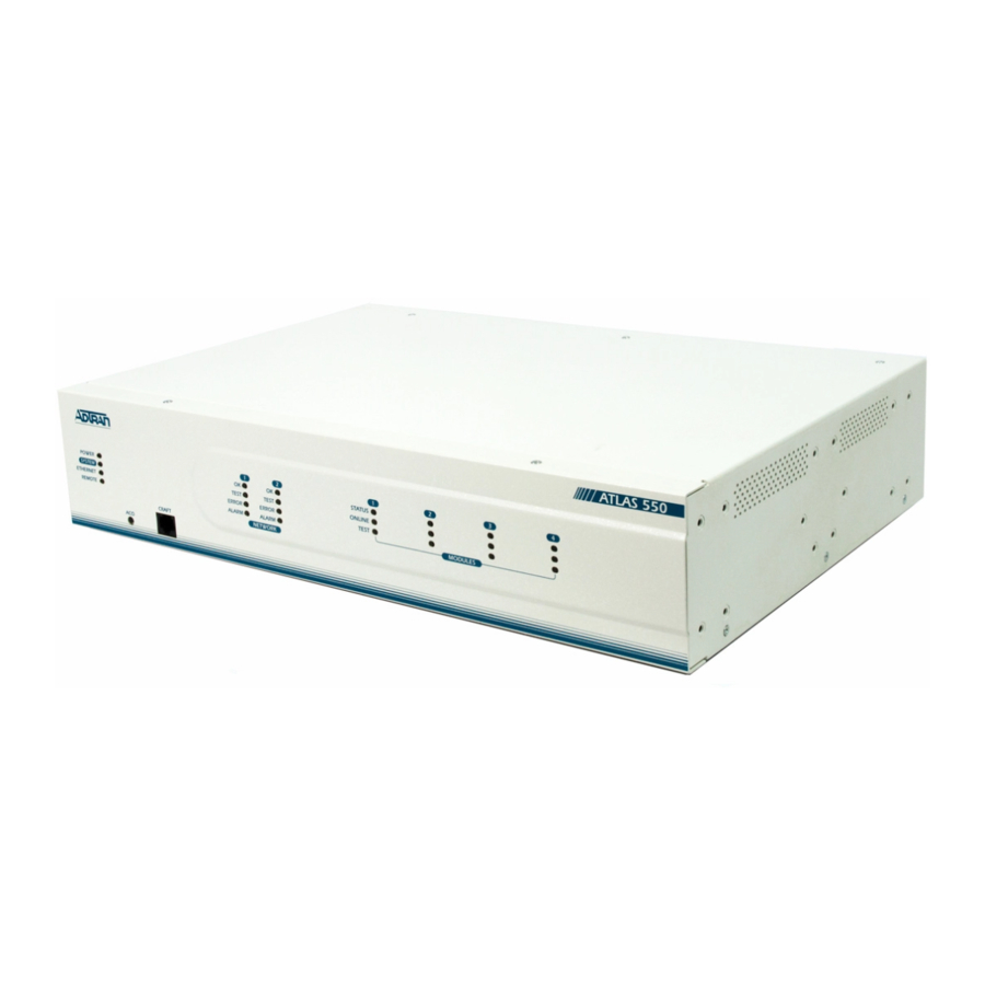
ADTRAN Atlas 550 Q&A
Hide thumbs
Also See for Atlas 550:
- System manual (412 pages) ,
- User manual (262 pages) ,
- Configuration manual (11 pages)
Table of Contents
Advertisement
Quick Links
Article ID: 1390
Q&A
How do I setup an Atlas 550/800 Plus/810 Plus for
voice compression and IP over frame relay?
Q:
How do I setup an Atlas 500/800 Plus/810 Plus for voice compression and IP over frame
relay?
A:
Introduction
The ATLAS Voice Compression Module combines with other ATLAS components to allow
voice and fax traffic to share the same lines as data and LAN traffic. A single Voice Compression
Module simultaneously compresses up to 30 channels for the ATLAS 550 and up to 32 channels
PLUS
PLUS
for the ATLAS 800
/810
for transmission over public or private frame relay networks or
dedicated leased lines. Voice and data traffic integration yields a dramatic reduction in
communication expenses.
PLUS
PLUS
The ATLAS 800
/810
Voice Compression Module (VCOM) occupies a single slot in the
chassis and is available in 8, 16, 24, and 32-channel configurations. A single ATLAS
PLUS
PLUS
800
/810
system with multiple Voice Compression Modules installed can simultaneously
compress up to 64 channels of voice. The ATLAS 550 Voice Compression Module is a plug-on
board for a user interface module occupying a single slot and is available in 4, 8, 16, and 24-
channel configurations. A single ATLAS 550 system with multiple Voice Compression Modules
installed can simultaneously compress up to 30 channels of voice.
The ATLAS Voice Compression Module interoperates with ADTRAN's Frame Relay Access
Device (FRAD) products, such as the Express 5200/5210 or ATLAS 550, when the FRADs are
equipped with FXS or FXO cards. Channelized T3, T1, Primary Rate ISDN (PRI), or Basic Rate
ISDN (BRI) circuits provide network access to the ATLAS Voice Compression Module.
The ATLAS Voice Compression Module automatically detects fax transmissions and locally
demodulates the fax, sending the baseband component of the fax over the link.
Before You Begin
PLUS
PLUS
Before configuring the ATLAS 550/800
/810
and Express 5200/5210s, the following
information must be obtained from the frame relay service provider:
Advertisement
Table of Contents

Related Manuals for ADTRAN Atlas 550


Summary of Contents for ADTRAN Atlas 550
- Page 1 The ATLAS Voice Compression Module combines with other ATLAS components to allow voice and fax traffic to share the same lines as data and LAN traffic. A single Voice Compression Module simultaneously compresses up to 30 channels for the ATLAS 550 and up to 32 channels PLUS...
-
Page 2: Configuring System Timing
You must also have an ATLAS 800 /810 with active frame relay software and a VCOM module. The ATLAS 550 comes with the frame relay software already active, but will also require a VCOM plug-on module. Overview This technical note shows the configuration for a host ATLAS 800PLUS that provides IP data and compressed voice traffic to two remote Express 5210s with dual FXS cards over frame relay. - Page 3 Figure 2 Configuring Packet Endpoints The ATLAS uses Packet Endpoints to terminate frame relay connections. 1. From the main menu go to Packet Manager/Packet Endpnts/Config. 2. Press the right arrow. A new entry will automatically be created. If an entry already exists, highlight the line item number and press the 'I' key to insert a new entry.
- Page 4 Figure 3 6. Change the Signaling Role to User. This tells the ATLAS that the endpoint will be connected to a Telco-provided frame relay service. 7. Select the proper Signaling Type as provided by the frame relay service provider. This sets the frame relay signaling type for this endpoint only and is independent of other interfaces on the ATLAS.
- Page 5 Figure 4 9. Press <enter> on the [+] symbol in the Sublinks column. 10. Create a new entry for each Permanent Virtual Circuit (PVC) on this frame relay line. 11. Name the sublink after the remote site to which you are connecting. 12.
- Page 6 Figure 5 14. Press <enter> on Config then change the Fragmentation Threshold to 220. This field tells the ATLAS what packet size to use for each fragment. The far end Express 5210 will also be fragmenting the packets it transmits to a size of 220. Fragmentation of the packets allows packets to be transmitted quickly instead of having the long delay associated with a large packet.
- Page 7 Figure 6 Configuring Packet Connects After the packet endpoint is created and configured with the appropriate DLCIs, the endpoint needs to be linked. In this example, we will be using the ATLAS' internal router. This configuration will require a packet connect from the endpoint, Atlanta sublink, to the internal router, as well as a packet connect from the endpoint, Birmingham sublink, to the internal router (see Figure 7).
- Page 8 Figure 7 If implementing an application that does not use the internal router, an additional packet endpoint would need to be created for the external router, then a packet connect would be required between the primary frame relay endpoint and the external router endpoint. Configuring Dedicated Maps Now that the packet endpoint has been created and linked, the endpoint must be mapped to a physical port on the ATLAS.
- Page 9 Figure 8 7. Press <enter> on the From Config option and the menu in Figure 9 will be displayed. Figure 9...
-
Page 10: Configuring The Router
8. Press <enter> on DS0 Selection and change it to reflect the number of channels used for the frame relay connection. In the example network of Figure 1, all 24 channels will be used so 1-24 is entered in the DS0 Selection menu field. Configuring the Router For the example network in Figure 1, we will be using Inverse Address Resolution Protocol (IARP) in conjunction with Version 2 (V2) of the Routing Information Protocol (RIP) to... -
Page 11: Configuring Dial Plan
Figure 11 4. Once the IARP and RIP packets have exchanged, you will then be able to see the updated routing table in the Routes menu. Configuring Dial Plan The Dial Plan will contain the configuration necessary to compress and uncompress the voice as well as route the voice calls based on the digits dialed. - Page 12 Figure 12 6. Press <enter> on Ifce Config to configure the specific options for this connection. 7. Press <enter> on DLCI and select the appropriate sublink for this specific connection. 8. Press <enter> on Voice Port and enter a value of 1. This option is used to send information to the remote site regarding which physical phone port to send the call to.
- Page 13 Figure 13 14. Go to the User Term menu again. Notice the contents of the Ifce Config option which is in the format of "DLCI.VoicePort". This allows the user to see the DLCI and Voice Port that a call will be routed to when the In#Accept digits are dialed. See Figure 14. 15.
- Page 14 Figure 14 16. Now that the entries are complete for the frame relay connection, the connection to the PBX must be configured. Create another entry in the User Term. 17. Under Slot/Svc and Port/PEP, select the slot and port which is connected to the PBX. For the example network, this will be slot 0, port 2.
- Page 15 Figure 15 20. Go to Ifce Config. Configure the channel mappings. The example network is using all 24 channels on the T1 between the ATLAS and the PBX, therefore First DS0 is 1 and Number of DS0s is 24. 21. Press <enter> on Signaling Method and select the appropriate RBS signaling which matches the PBX.
- Page 16 Configuring the Network Port on the Express 5210 1. Using a PC connected to the Control Port, login to the unit using the default password of "adtran". 2. From the Main Menu, go to Configuration, Network Port, then press <enter> on Physical Layer Options.
- Page 17 Figure 17 3. Return to the previous menu, go to Frame Relay Options, then press <enter> on Signal Type. Select the appropriate Signal Type, either ANSI T1.617-D or LMI, to match what the frame relay provider is using on their frame relay switch. In the example network, we will be using ANSI T1.617-D frame relay signaling.
- Page 18 4. Return to the previous menu, then go to PVC Options. Create a new entry and enter the remote site's locally significant DLCI number for the DLCI option. For the example network in Figure 1, the DLCI should be 20. If the Committed Information Rate (CIR) is known for this PVC, enter the value in the CIR option field.
- Page 19 Figure 20 2. Press <enter> on DLCI Mapping. The DLCI entered for L1 and L2 should be the remote site's locally significant DLCI. For the example network in Figure 1, the DLCI for both voice ports is 20, as shown in Figure 21. Figure 21...
- Page 20 3. Return to the previous menu. Verify that the Voice Coder option matches the Voice Compression option on the host ATLAS. See Figure 20. 4. Return to the main menu. The unit will prompt you to save the changes made. Press 'Y' to confirm the save.
-
Page 21: Sample Configuration Files
Figure 23 Figure 24 Sample Configuration Files... -
Page 22: Download The Configuration
6. Please refer to the readme.txt file for full instructions on downloading the configuration file to the ATLAS unit. If you experience any problems using your ADTRAN product, please contact ADTRAN Technical Support.
Need help?
Do you have a question about the Atlas 550 and is the answer not in the manual?
Questions and answers