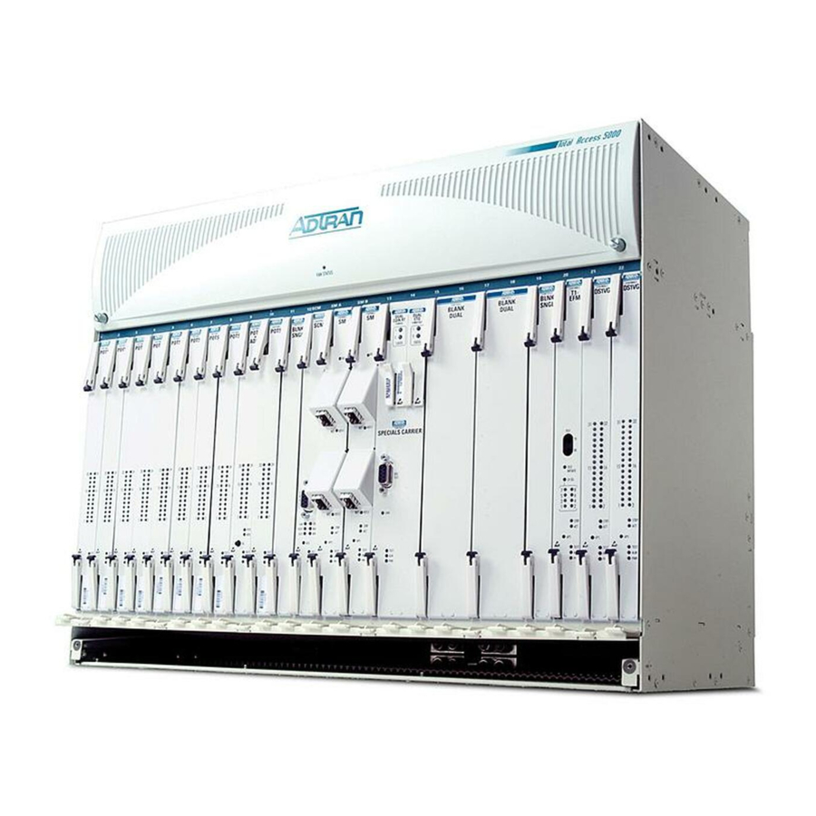
Total Access 5000 Business Services Deployment Guide Trademarks Any brand names and product names included in this document are trademarks, registered trademarks, or trade names of their respective holders. To the Holder of this Document ® The contents of this document are current as of the date of publication. ADTRAN reserves the right to change the contents without prior notice. In no event will ADTRAN be liable for any special, incidental, or consequential damages or for commercial losses even if ADTRAN has been advised thereof as a result of issue of this document. About this Document This document supports Total Access 5000 System Release 5.1. Deployment Guides provide quick start installation and turn up information for the Total Access 5000 system deploying a specific network application. The intended audience for this information is the craft person responsible for the initial system installation. This guide provides configuration steps needed to achieve traffic flow‐through, diagrams, descriptions of functionality, and configuration examples. For detailed installation, provisioning, and user interface information for each individual system component, refer to the Installation and Maintenance Guide for each applicable common, access, and line module. ® 901 Explorer Boulevard P.O. Box 140000 Huntsville, AL 35814‐4000 United States (256) 963‐8000...
OTHERWISE) ARISING IN ANY WAY OUT OF THE USE OF THIS SOFTWARE, EVEN IF ADVISED OF THE POSSIBILITY OF SUCH DAMAGE. @(#)socket.h8.6 (Berkeley) 5/3/95 Revision History Revision Date Description April 2010 Initial release. This document supports Total Access 5000 System Release 5.1.0 and Carrier Ethernet. Conventions The following typographical conventions are used in this document: This font indicates a cross‐reference link. This font indicates screen menus, fields, and parameters. indicates keyboard keys ( E , E , A ). Keys that are to be pressed simultaneously HIS FONT NTER are shown with a plus sign ( A indicates that the A key and key should be pressed at the same time ). This font indicates references to other documentation and is also used for emphasis. This font indicates on‐screen messages and prompts. This ...
Page 6
Total Access 5000 Business Services Deployment Guide Hazard Classifications The following hazard classifications are used in this document: DANGER DANGER indicates a hazard with a high level of risk which, if not avoided, will result in death or serious injury. WARNING WARNING indicates a hazard with a medium level of risk which, if not avoided, could result in death or serious injury. CAUTION CAUTION indicates a hazard with a low level of risk which, if not avoided, could result in minor or moderate injury. CAUTION can also be used to alert against unsafe practices associated with events that could lead to personal injury. NOTICE Notice call‐outs indicate a potentially hazardous situation not related to personal injury, such as messages related to property damage only. NOTE Notes inform the user of additional, but essential, information or features. Metric Conversion The Total Access 5000 is designed to fit standard 19‐inch and 23‐inch racks, occupying 2U or 6U of vertical space. 1U equals 1 rack unit of vertical height, which equals 1.75 inches or 44.5 millimeters. The following metric conversions apply: • 19 inches = 482 millimeters • 23 inches = 584 millimeters • 9U (15.75 inches) = 400 millimeters Other measurements are listed in metric and standard notations, where applicable. 65K510DEP08-1A...
Page 7
Icons The following icons are used throughout the ADTRAN document suite: jobAid installation guide deployment guide application guide reference guide diagnostic guide safety and regulatory engineering guide release notes upgrade guide user guide Training ADTRAN offers training courses on our products. These courses include overviews on product features and functions while covering applications of ADTRAN product lines. ADTRAN provides a variety of training options, including customized training and courses taught at our facilities or at customer sites. For inquiries concerning training, contact ADTRAN: Training Phone: 800‐615‐1176, ext. 6303 Training Fax: 256‐963‐6217 Training Email:training@adtran.com 65K510DEP08-1A...
Page 8
Total Access 5000 Business Services Deployment Guide viii 65K510DEP08-1A...
Introduction Scope of this Guide This guide provides the minimum configuration steps needed for the Ethernet over Copper (EoCu), Business Service Migration (BSM), Ethernet over TDM (EoTDM), and Ethernet over Fiber (EoF) deployments. In this Guide This guide contains the topics listed in Table Intro‐1. Table Intro-1. Topic List Section Topic Section 1 Business Services Overview Section 2 Installation Section 3 Common Provisioning Section 4 EoCu Provisioning Section 5 BSM Provisioning Section 6 EoTDM Provisioning Section 7 EoF Provisioning Appendix A Link Aggregation Guide Appendix B SHDSL Rate Reach Information Appendix C Ethernet OAM Provisioning Appendix D TWAMP Provisioning Appendix E Dynamic Counters Provisioning Appendix F...
Total Access 5000 Business Services Deployment Guide Table Intro-1. Topic List Section Topic Appendix J GigE Star Provisioning Appendix K GigE Linear Chain Provisioning Appendix L RPR Provisioning Appendix M Add/Remove Node from RPR Ring Appendix N ERPS Provisioning Appendix O Loopback Provisioning Related Documentation Refer to Table Intro‐2 for additional, detailed system information concerning the Business Services deployment. For detailed component information, refer to the applicable Installation and Maintenance Guides and Job Aids for the individual component product. Table Intro-2. Related System Documentation Title Part Number Total Access/NetVanta Carrier CLI Dictionary 6TANV510CLI‐35 Total Access 5000/5006 Engineering and Ordering Guide System Release 5.1...
Section 1 Business Services Overview Scope of this Section This section provides an overview of the Ethernet over Copper (EoCu), Business Services Migration (BSM), Ethernet over TDM (EoTDM), and Ethernet over Fiber (EoF) applications. In addition, the section also provides a Command Line Interface (CLI) overview. In this Section This section contains the following topics: Table 1-1. Section 1 Topics Topic See Page Ethernet over Copper Overview 1‐2 Business Services Migration Overview 1‐5 Ethernet over TDM Overview 1‐8 Ethernet over Fiber Overview 1‐12 Command Line Interface Overview 1‐14 65K510DEP08-1A...
Total Access 5000 Business Services Deployment Guide Ethernet over Copper Overview The Total Access 5000 is a carrier class multi‐service access and aggregation platform. It supports Internet Protocol Television (IPTV) and Voice over IP (VoIP) across both copper and fiber interfaces while simultaneously supporting legacy services. These services include basic Plain Old Telephone Service (POTS) and Digital Subscriber Line (DSL). The end to end EoCu solution (Figure 1‐1) encompasses the latest Metro Ethernet Forum (MEF) certified Ethernet in the First Mile (EFM) over copper network termination units (NTU), which leverages existing copper facilities to offer extended reach Carrier Ethernet up to 45Mbps. The EoCu solution offers the following features: • Consistent Operations, Administration and Maintenance (OAM) • Traffic management and flow‐through provisioning • Resiliency through dynamic circuit removal and restoration • Electrical and Optical Ethernet connections to the customer Total Access 5000 SHDSL EoCu (x8) General Application Diagram Central Office SHDSL...
Section 1, Business Services Overview - Ethernet over Copper Overview Ethernet over Copper Components List Table 1‐2 lists the products needed for the EoCu deployment. Table 1-2. Deployment Part Numbers Part Number Description CLEI Total Access 5000 Components 1187001L1 23‐Inch Chassis BVM2V10G_ _ 1187010L1 System Controller Module (SCM) BVCUD0YM_ _ 1187010G2 SCM, Second Generation BVC1AA6E_ _ 1187011G1 Bridging SCM BVC1ABGE_ _ 1187020G1 Switch Module 2 Gigabit, no Ring Generator BVL2N0NC_ _ 1187020G2 Switch Module 2 Gigabit, w/Ring Generator...
Page 34
Total Access 5000 Business Services Deployment Guide Table 1-2. Deployment Part Numbers (Continued) Part Number Description CLEI 1187250G1 EFM Bonding Protection Module BVL3ACUD_ _ 1187450G1 Access Module Input/Output Dual Champ 64‐Pin Push‐ BVPQADJM_ _ Through Panel (AMIO2‐CH64P) 1187925L1/G1 AMIO1 Blank Panel Other Components 1200633G4 NetVanta 838 SIM5K10B_ _ 1172839G1 NetVanta 838 EFM NTE Enhanced Protection VAMLC00B_ _ CAUTION Due to compliance certification requirements, only SFPs supplied by ADTRAN are to be used with the Total Access 5000 modules. ADTRAN cannot certify system integrity when non ADTRAN supplied SFPs are used. 65K510DEP08-1A...
Section 1, Business Services Overview - Business Services Migration Overview Business Services Migration Overview The Business Services Migration (BSM) application applies to legacy customer routers or integrated access devices already using a variety of link layer protocols to carry IP traffic over DS1. Figure 1‐2 displays legacy customer routers connected through a SONET and TDM infra‐ structure that can be migrated to an Ethernet infrastructure through the use of the Total Access 5000. Customer Site Router SONET SONET Core Central Office #1 Central Office DS1 over Channelized Optical Interface Customer Site Channelized Total Access Router 5000 GigE...
Total Access 5000 Business Services Deployment Guide Routers 2G LAG with LACP for Redundancy Internet Access, Local LAN Total Access 5000 PPP T1 To Customer (Future Availability) Netvanta 873 (x2) Ch. DS3 to M13 Routers SHDSL PPP T1 To Customer...
Total Access 5000 Business Services Deployment Guide Ethernet over TDM Overview The end to end Ethernet over TDM (EoTDM) solution (Figure 1‐4 and Figure 1‐5) encom‐ passes the latest Metro Ethernet Forum (MEF) certified Ethernet in the First Mile (EFM) over Time Division Multiplexed (TDM) Network Termination Units (NTU), which leverages existing TDM/SDH/SONET facilities to offer extended reach Carrier Ethernet up to 135Mbps. The EoTDM offers the following features: • Consistent Operations, Administration, and Maintenance (OAM) • Traffic management and flow‐through provisioning • Resiliency through dynamic circuit removal and restoration • Electrical and Optical Ethernet connections to the customer Total Access 5000 EoTDM SONET General Multiplexer (Central Office) Application Diagram Central Office DS3s Router Customer Site...
Total Access 5000 Business Services Deployment Guide Ethernet over TDM Components List Table 1‐2 lists the products needed for the EoTDM deployment. Table 1-4. Deployment Part Numbers Part Number Description CLEI Total Access 5000 Components 1187001L1 23‐Inch Chassis BVM2V10G_ _ 1187010L1 System Controller Module (SCM) BVCUD0YM_ _ 1187010G2 SCM, Second Generation BVC1AA6E_ _ 1187011G1 Bridging SCM BVC1ABGE_ _ 1187020E1 Switch Module 2 Gigabit Ethernet BVL2NSMC_ _ 1187020G1 Switch Module 2 Gigabit, no Ring Generator BVL2N0NC_ _...
Page 41
Section 1, Business Services Overview - Ethernet over TDM Overview Table 1-4. Deployment Part Numbers (Continued) Part Number Description CLEI Other Components 1200637G4 NetVanta 814 T1/E1 EFM NTE SIM5700B_ _ 1200639G1 NetVanta 873 EFM NTE SIM6J00A_ _ 1200637G2 NetVanta 818 T1/E1 EFM NTE SIM5800B_ _ CAUTION Due to compliance certification requirements, only SFPs supplied by ADTRAN are to be used with the Total Access 5000 modules. ADTRAN cannot certify system integrity when non ADTRAN supplied SFPs are used. 65K510DEP08-1A 1-11...
Total Access 5000 Business Services Deployment Guide Ethernet over Fiber Overview Enhancing the Total Access 5000 to support Ethernet services aggregation is achieved by the addition of the Gigabit Ethernet 8‐Port Line Module (GE 8‐Port LM). The GE 8‐Port LM can terminate up to 8 GigE facilities, allowing a single Total Access 5000 shelf to terminate multiple 10Mbps, 100Mbps, and/or 1 Gbps access facilities. The GE 8‐Port LM can be used in conjunction with the existing EoCu and/or EoTDM services, allowing multiple business service delivery methods to be provided from a single Total Access 5000 shelf. In addition to sub‐aggregating existing Ethernet over Fiber (EoF) facilities, the Total Access 5000 and associated GE 8‐Port LM is capable of delivering new Ethernet services directly to customer locations with fiber connectivity; supporting scalable service rates of up to 1 Gbps. Further, Service Providers who have already deployed the Total Access 5000 for delivering EoCu and/or EoTDM, new EoF services delivery can be added to the solution portfolio without a lengthy and expensive standardization process thus improving the solutions time to market. The NetVanta 8000 family of Etherent over Fiber NTU would be sub‐tended from the Total Access 5000 via this new GE 8‐Port LM to deliver the Ethernet service to the customer premises. Total Access 5000 GigE General Application Diagram Central Office GE Optical Fiber GigE Router...
Total Access 5000 Business Services Deployment Guide Command Line Interface Overview This section details the following information: • Command Modes • CLI Shortcuts • CLI Error Messages • CLI Input Descriptions Command Modes The Total Access 5000 CLI has three command modes, Basic, Application, and Enable. Each mode supports a specific set of commands. For example, all interface configuration commands are accessible only through the Enable mode. Table 1‐6 shows a brief description of each command mode. Table 1-6. Command Modes Mode Access by... Prompt With this mode... Basic Beginning a session >...
Section 1, Business Services Overview - Command Line Interface Overview Table 1-7. CLI Shortcuts Shortcut Description Use the up arrow to re‐display a previously entered command. The up Up arrow or arrow can cycle through all commands entered starting with the most recent command. After entering a partial, but unique, command, press the to complete the command. The command displays on the command prompt and waits for input. Use the for any of the following: • Display a list of all subcommands in the current mode. • Display a list of available commands beginning with certain letter(s). • Obtain syntax help for a specific command by entering the command, a space, and then a question mark (?). The CLI displays the range of values and a brief description of the next parameter expected for that particular command. Use to jump to the beginning of the displayed command line. Use to jump to the end of the displayed command line. Use to clear the current displayed command line.
Total Access 5000 Business Services Deployment Guide CLI Input Descriptions Table 1‐9 lists and defines the inputs used throughout the CLI. Table 1-9. Input Descriptions Input Syntax Input Example Description <x-y> ‐2‐4000 Use this input to enter a range by entering the x and y variables. The x and y variables are numeric and can be negative. <x-n> 1‐n Use this input to enter an infinite range by entering the x variable. The x variable is numeric and can be nega‐ tive. <x> Use this input to enter a single number. <x,y-z,a> ‐1,4‐10,20‐22 Use this input to enter a comma delimited numeric list without spaces. This input can include ranges. <HH:MM:SS> 12:30:01 Use this input to enter the time in hour‐minute‐second format.
Page 47
Section 1, Business Services Overview - Command Line Interface Overview Table 1-9. Input Descriptions (Continued) Input Syntax Input Example Description <slot/port> Use this input to enter the slot and port. <slot> Use this input to enter the slot. Valid inputs are 0 ‐ 22 for module slots, A for SM A, B for SM B, S for the SCU, and F for the fan module. <port> Use this input to enter the port number. 65K510DEP08-1A 1-17...
Page 48
Total Access 5000 Business Services Deployment Guide 1-18 65K510DEP08-1A...
Section 2 Installation Scope of this Section This section provides installation information for the Total Access 5000 Chassis, Fan Module, Access Modules, and SMIO3. In this Section This section contains the following topics: Table 2-1. Section 2 Topics Topic See Page Tools Required for Chassis Installation 2‐2 Install the SMIO3 2‐3 Install the Fan Module and Fan Filter 2‐5 Mount the Chassis 2‐7 Ground the Chassis 2‐8 Connect the Power Terminal 2‐9 Install and Connect the Rear Panel Components 2‐11 Install the Front Panel Modules 2‐16 Install the NetVanta 800/80000 2‐27 65K510DEP08-1A...
Total Access 5000 Business Services Deployment Guide Tools Required for Chassis Installation The tools required to install the chassis are as follows: • A #2 phillips‐head screwdriver • Crimping tool for power lugs • Wire strippers • Wire‐wrap tool • Side cutters • Torque wrench with a range from 2 to 37 inch/pounds • Ohmmeter The items required to install the chassis are as follows: • Screws for mounting the chassis to the Central Office (CO) racks • Insulated wire, stranded, copper, (2 AWG to 6 AWG) that is at least equal to the same size of the power wire for grounding the chassis to the frame • Data cables terminated for the Total Access 5000 50‐pin or 64‐pin connections • Insulated wire for power connections WARNING To prevent electrical shock, do not install equipment in a wet location or during a lightning storm.
Section 2, Installation - Install the SMIO3 Install the SMIO3 This subsection details the following information: • SMIO3 Description • Installation Steps SMIO3 Description The Switch Module Input/Output 3 (SMIO3) supports one System Controller Module (SCM) and two Switch Modules (SM). The SMIO3 provides the following: • Physical interface (3 slots) to the Total Access 5000 backplane for the SCM and two SMs • Physical communication paths between the SCM and the SMs • Communication interface ports to the SCM that enable management of the Total Access 5000 system • Wire‐wrap terminals for external clocks, alarm I/O, testing, and voltage • Control signals and a power path to the Fan Module Installation Steps The SMIO3 attaches to the back of the Total Access 5000 chassis. To install the SMIO3, complete the following: CAUTION If the chassis is rack mounted, be sure that the chassis is square and not distorted by the rack frame before installing the SMIO3. To aid installation, loosen the chassis mounting bolts to allow the chassis to become square. NOTE Before installing the chassis, install the SMIO3. Installing the SMIO3 ensures the relay rack, if not square, will not warp the chassis. If not done properly, the SMIO3 mounting screws will not mate with the chassis. For installation...
Total Access 5000 Business Services Deployment Guide 3/8” Screws Stand-offs SMIO3 3/4” Screws Figure 2-1. Installing the SMIO3 NOTE Before installing the chassis in a CO frame, the paint must be removed from the surface of the CO frame where the mounting brackets come in contact with that frame. Antioxidants must be applied to these areas after the paint has been removed. 65K510DEP08-1A...
Section 2, Installation - Install the Fan Module and Fan Filter Install the Fan Module and Fan Filter This subsection details the following information: • Description of the Fan Module • Installation steps for installing the Fan Module and Fan Filter Fan Module Description The Fan Module consists of a sheet metal tray that holds four fans rated at a nominal –48 VDC. The Fan Module is mounted from the front of the rack and is installed into the top slot of the Total Access 5000 Chassis. The Fan Module is designed to provide forced air ventilation to cool a fully populated Total Access 5000 Chassis. Power is supplied to the Fan Module through two independent circuits that are controlled as a group. Each circuit supplies power to two fans, which are connected in parallel. When fully inserted, the Fan Module connects to the SMIO3. The SMIO3 routes power and serial commu‐ nications from the switch module to the Fan Module. The fan microprocessor samples the speed of each fan and reports an alarm condition for fan failure or eminent fan failure. Installation Steps To install the Fan Module, complete the following: 1. Push the Fan Module firmly into the top slot of the chassis (see Figure 2‐2). Figure 2-2.
Total Access 5000 Business Services Deployment Guide NOTE The Fan Filter is located at the bottom of the Total Access 5000 chassis and is accessed from the front of the chassis (see Figure 2‐3). 3. Insert the fan filter at the bottom of the chassis with the springs oriented toward the back of the chassis and the aluminum filter mesh facing upward. 4. Gently push the filter in and up until it engages with the chassis. Figure 2-3. 23-Inch Fan Filter Installation 65K510DEP08-1A...
Section 2, Installation - Mount the Chassis Mount the Chassis NOTE When mounting the chassis, leave the mounting screws loose until the SMIO3 and fan module have been installed. The chassis is shipped with two mounting brackets that are used to install the chassis with either a 2‐inch, 3.3‐inch, 4.1‐inch or 5‐inch front projection. Each bracket is attached with five screws, which are supplied with the chassis. Refer to Figure 2‐4 for mounting locations and mounting bracket orientations. 2-Inch Front Projection 5-Inch Front Projection 3.3-Inch Front Projection 4.1-Inch Front Projection Figure 2-4. Mounting Bracket Locations 65K510DEP08-1A...
Total Access 5000 Business Services Deployment Guide Ground the Chassis The frame ground lug can accommodate from 2 AWG to 6 AWG copper, stranded wire. When connecting the frame ground, use a wire gauge that is at least as large a gauge as the power connections (see Figure 2‐5). To make the ground connection to the chassis, complete the following: 1. Ensure that the power is disconnected at the source. 2. Remove the connection hardware from both chassis ground bolts. 3. Clean the surface of the chassis grounding area and apply an appropriate antioxidant. 4. Strip the ground wire 5/8 of an inch and crimp the chassis ground lug to the wire. 5. Connect the ground wire to the chassis ground bolts. 6. Install the lock washers and hex nuts. 7. Torque the hex nuts to 24 inch/pounds. 8. Secure the other end of the ground wire to a suitable rack ground according to local Central Office (CO) practices. Ground Figure 2-5. Chassis Rear View, Ground Lug Location...
Section 2, Installation - Connect the Power Terminal Connect the Power Terminal The chassis provides redundant power terminal inputs. Two sources of –48 VDC must be provided to use the redundant power feature. The two power inputs are labeled –48V A and –48V B and are located on the back of the chassis (see Figure 2‐6). NOTE A readily accessible disconnect device such as a rackmount fuse and alarm panel that is suitably approved and rated, should be incorporated in the fixed wiring. NOTICE The Total Access 5000 System is designed for a reliably grounded ‐48V nominal DC supply. This requires the positive terminal to be referenced to earth ground. Make this reference connection at either the source (rectifier or battery) or at the frame. Powering by any other means may void the warranty of the product. To connect power to the chassis, complete the following: 1. Determine which fuse pairs are to supply power to the Total Access 5000 shelf and remove the fuses from the A and B slots for the pair. 2. Ensure the power is disconnected at the source. 3. Open the plastic power terminal doors on the rear of the chassis to access the power terminals. 4. Cut four lengths of appropriately sized wire to reach from the terminals on the fuse and alarm panel to the power terminals on the Total Access 5000 Chassis. Leave enough slack ...
Section 2, Installation - Install and Connect the Rear Panel Components Install and Connect the Rear Panel Components This subsection details the connection and installation of the Total Access 5000 rear panels. Connect the SMIO3 The plastic guard that covers the wire‐wrap terminals on the SMIO3 is a safety feature that prevents personnel and equipment from contacting exposed voltages. NOTE The SMIO3 is already installed but must be connected. To remove the guard, complete the following procedure: 1. Using a #1 phillips‐head screwdriver, remove the three screws that secure the guard. 2. Carefully remove the guard by pulling it straight from the SMIO3. To reinstall the guard, reverse the previous procedures. Input and output connectors on the SMIO3 consist of the following: • Communications Interface Ports – Physical interfaces to the SCM, consisting of RS‐232‐ compatible ports for Admin and Network Management functions, and an Ethernet LAN for Management functions • Terminal Block Connections – Labeled blocks of wire‐wrap terminals for alarms, alarm cut off, external voltage, clock functions, test bus, and shelf linking functions NOTE Refer to the Total Access 5000 Switch Module I/O 3 (SMIO3) Installation and Maintenance Practice (P/N 61187051G1‐5) for detailed information.
Total Access 5000 Business Services Deployment Guide NOTE The AMIO2‐CH50P supports the COMBO A2+ 24‐Port and RPOTS 24‐Port Access Modules. AMIO2-CH64P Rear Panel The AMIO2‐CH64P covers two module slots on the rear of the Total Access 5000 Chassis. The AMIO2‐CH64P is designed to hold two standard entry 64‐pin male champ connector cables. For standard entry, the cable exits the 90° connector hood on the pin 1 end of the male champ connector. NOTE Push‐through panels are provided with four Captive Champ Screws for installation of two connectors to the panel. Use two screws for each connector, one for the mounting bracket, the second to secure the connector to the panel. The Captive Champ Screw provided with the cable must be replaced if it is not a 0.35 inch screw. LMIO2-CH64B Rear Panel The LMIO2‐CH64B is an interconnect for two line module slots on the rear of the chassis. The LMIO2‐CH64B module provides metallic access to 32 four‐wire circuits per access module installed for a maximum of 32 four‐wire circuits. Two 64‐pin male 90° champ connectors attach to the LMIO2‐CH64B, and provide connection and stabilization between modules in the Total Access 5000 Chassis and external cable connections that use 64‐pin connectors. For standard entry, the cable exits the 90° connector hood on the pin 1 end of the male champ connector. LMIO2-CH50D Rear Panel The LMIO2‐CH50D is an interconnect for two line module slots on the rear of the Total Access 5000 Chassis. The LMIO2‐CH50D provides metallic access to 8 four‐wire circuits per access module installed for a maximum of 16 four‐wire circuits. Two 50‐pin male 90° champ connectors attach to the LMIO2‐CH50D, and provide connection and stabilization between ...
Section 2, Installation - Install and Connect the Rear Panel Components LMIO2 High-Speed Rear Panel The LMIO2 High Speed Rear Panel provides a high‐speed data path from a front panel SFP to an adjacent GE 4‐Port, GE 8‐Port, or RPR Line Module. In a packet ring configuration, the LMIO2 High‐Speed Rear Panel is used to provide a high speed data link and handshake communications between two Total Access 5000 RPR Line Modules. Both applications can also be used for automatic protection switching (APS). LMIO2 DS3 BNC Rear Panel The LMIO2 DS3 BNC Rear Panel is a series of I/O modules for the ATM DS3 Line Modules on the rear of the Total Access 5000 chassis. The LMIO2 DS3 BNC Rear Panel provides Tx (out) and Rx (in) BNC connectors for the ATM DS3. NOTE The LMIO2 DS3 BNC Rear Panel only supports the DS3 ATM Line Module. Installing a DS3 BNC Rear Panel To install the DS3 BNC Rear Panel, complete the following: 1.
Section 2, Installation - Install and Connect the Rear Panel Components Install the Rear Panels To install the push‐through panels, complete the following procedure (see Figure 2‐8 and Table 2‐2): Figure 2-8. Installing the Rear Panels Table 2-2. Rear Panel Installation Steps Step Description Position the rear panel on the back of the chassis so that the middle notch on the panel aligns with the chassis alignment pin. The rear panel is provided with a set of captive screws. These screws insert into the chassis’ screw mounting holes. Use a Phillips screwdriver to tighten the captive screws, securing the panel to the chassis. Install the Champ Mounting Bracket to the bottom of the 90° male champ connector using one #4‐40 x 0.35 inch Captive Screw. The rear panel is provided with a set of #4‐40 x 0.35 inch Captive Screws for installation of two connectors to the panel. Use two screws for each con‐ nector, one for the mounting bracket, the second to secure the connector to the panel (see Step 3). Replace the Captive Screw provided with the cable if it is not a 0.35 inch screw. Install the 90° male champ connector to the rear panel by sliding the mounting bracket down ...
Total Access 5000 Business Services Deployment Guide Install the Front Panel Modules This subsection details the description and installation of the Total Access 5000 front panel modules. SCM Description The System Controller Module (SCM) provides a logical user interface to the entire system. The SCM enables the provisioning of modules, alarm status monitoring, querying of perfor‐ mance data, and initiation of tests for any module in the shelf. The SCM provides various interfaces for both local and remote management of the Total Access 5000 system. It supports Simple Network Management Protocol (SNMP), Command Line Interface (CLI), Transaction Language 1 (TL1), Telnet, and local craft access for the entire Total Access 5000 system. SCM, Second Generation Description The SCM, Second Generation (SCM G2) provides a logical user interface to the entire system. The SCM G2 enables the provisioning of modules, alarm status monitoring, the querying of performance data, and the initiation of tests for any module in the shelf. The SCM G2 provides various interfaces for both local and remote management of the Total Access 5000 system, including a secondary Ethernet port on the front panel with auto cross‐over correction that supports a DHCP server. The SCM G2 supports SNMP, CLI, TL1, Telnet, SSHv2, and local craft access for the entire Total Access 5000 system. Bridging SCM Description The Bridging SCM provides a logical user interface to the entire system. The Bridging SCM enables the provisioning of modules, alarm status monitoring, the querying of performance data, and the initiation of tests for any module in the shelf. The Bridging SCM provides various interfaces for both local and remote management of the Total Access 5000 system. The ...
Section 2, Installation - Install the Front Panel Modules Install the SCM To install the SCM, complete the following procedure: NOTE The SMIO3 must be installed before installing the SCM. 1. Pull the ejector latches, located on the upper and lower left‐hand side of the SCM front panel, from the closed positions. 2. Hold the SCM by the front panel while supporting the bottom edge of the module with the ejector latches opened to engage the chassis edges. 3. Align the module edges to fit in the lower and upper guide grooves for the slot labeled 12/SCM 4. Slide the module into the module slot. Apply simultaneous thumb pressure at the top and bottom of the module (to the right of the ejector latches) to ensure that the module is firmly seated against the backplane of the chassis. 5. Secure the SCM in place by rotating the ejector latches into the locked positions. GigE SM Description The GigE Switch Module (SM) provides network data aggregation for the Total Access 5000 system. The GigE SM switches Ethernet traffic from the SFP inputs to the Access Module slots. The GigE SM controls common system functions and communication between access modules and the SCM. The GigE SM interfaces to the high speed backplane through the SMIO3. Install the GigE SM To install the GigE SM, complete the following: NOTE The SMIO3 must be installed prior to installing the GigE SM.
Total Access 5000 Business Services Deployment Guide 8. Route the copper or optical cable to the cable tray located at the bottom of the module slots and dress with appropriate ties. Install the SFPs CAUTION Due to compliance certification requirements, only SFPs supplied by ADTRAN are to be used with the Total Access 5000 modules. ADTRAN cannot certify system integrity when non ADTRAN supplied SFPs are used. To install an SFP into an appropriate module, complete the following: 1. Inspect the SFP for damage. If damaged, file a claim with the carrier and then contact ADTRAN Customer Service. 2. Insert the SFP into the SFP cage on the switch module, with the label from the manufacturer facing to the right. Slide the SFP all the way into the cage until it clicks into place. 3. Remove the safety cap from the optical connectors of the SFP. 4. Insert the fiber connector into the SFP until it clicks into place. CAUTION Do not attempt to remove the SFP with the fiber installed. 32-Port SHDSL EFM Description The 32‐Port SHDSL EFM provides 32 SHDSL links that can be bonded with Ethernet in the first mile (EFM). Each SHDSL link is capable of data rates from 192 kbps to 5.7 Mbps in 64 kbps increments. For proper functionality, the 32‐Port SHDSL EFM must be installed in a Total Access 5000 shelf that has a SM installed. 2-18...
Section 2, Installation - Install the Front Panel Modules EFM Bonding Protection Module Description The EFM Protect Access Module provides EFM bonding engine protection for any EFM SHDSL or DS1 EFM (1187802L1) access module installed in a Total Access 5000 system beginning with System Release 3.2. These modules must support EFM bonding and have been cross‐slot provisioned. Install the EFM Bonding Protection Module NOTE ADTRAN recommends installing the EFM Protect Access Module in slot 11 or 21 of the Total Access 5000 chassis. To install the EFM Protect Access Module, complete the following steps: 1. Pull the ejector latches on the EFM Protect Access Module, located on the upper and lower left‐hand side of the EFM Bonding Protection Module front panel, from the closed positions. 2. Hold the EFM Protect Access Module by the front panel while supporting the bottom edge of the module with the ejector latches opened to engage the chassis. 3. Align the EFM Protect Access Module edges to fit in the lower and upper guide grooves of the module slot. 4. Slide the EFM Protect Access Module into the module slot. Apply simultaneous thumb ...
Total Access 5000 Business Services Deployment Guide CH DS3 PPP/MLPPP 3-Port Line Module Description The CH DS3 PPP/MLPPP 3‐Port Line Module provides channelized Point‐to‐Point Protocol (PPP) and Multi‐Link Point‐to‐Point Protocol (MLPPP) network connectivity to a Total Access 5000 system by way of three channelized DS3 interfaces. Each channelized interface provides connectivity for 28 DS1 channels. PPP T1 Link to Ethernet PPP operates at the data link layer and provides end‐to‐end connectivity for devices across a point‐to‐point link. PPP is made up of a suite of protocols, including LCP, authentication, and NCP (IPCP only), used to establish and maintain connectivity. The CH DS3 PPP/MLPPP 3‐ Port Line Module will forward frames from a T1 channel with PPP encapsulation to the Ethernet uplink with a single S‐tag. MLPPP groups can contain a maximum of eight T1 channels. DS3 EFM 4-Port Line Module Description The DS3 EFM 4‐Port provides four DS3 interfaces to the Total Access 5000 shelf. The DS3 EFM 4‐Port is designed for use as an end Ethernet First Mile (EFM) bonding interface that provides aggregate Ethernet connectivity to additional Total Access 5000 Chassis or to NetVanta DS3 EFM Network Circuit Terminating Equipment (NCTE). The DS3 EFM 4‐Port provides four DS3 signals consisting of digital data transmitted at 44.736 ...
Section 2, Installation - Install the Front Panel Modules DS3 EFM 3-Port Line Module Description The DS3 EFM 3‐Port provides three DS3 interfaces to the Total Access 5000 shelf. The DS3 EFM 3‐Port is designed for use as an end EFM bonding interface that provides aggregate Ethernet connectivity to additional Total Access 5000 Chassis or to NetVanta DS3 EFM NTE. The DS3 EFM 3‐Port provides 3 DS3 ports that can support bonding up to 84 DS1s to form up to a maximum of 42 EFM groups. NOTE • The LMIO DS3 BNC Rear Panel must be installed prior to insertion of the DS3 EFM 4‐Port into the chassis. In a 1:1 redundant configuration, the DS3 EFM 4‐Port modules must be installed in consecutive odd ‐ even slots. • The LMIO DS3 BNC Rear Panel occupies two slots. Slot 11 cannot be used since slot 12/SCM , SM A , and SM B slots are already occupied by the SMIO3 rear panel.
Total Access 5000 Business Services Deployment Guide to a Total Access 5000 Switch Module. Small Form‐factor Pluggable (SFP) cages are provided for inputs on the front panel of each module for maximum flexibility of the interfaces. CAUTION Due to compliance certification requirements, only SFPs supplied by ADTRAN can be used with the GE 4‐Port Line Module. ADTRAN cannot certify system integrity with other SFPs. NOTE • A LMIO2‐CH64B must be installed prior to installing the GE 4‐Port Line Module. • For redundant configuration, the Total Access 5000 LMIO2 Rear Panel must be installed prior to installing the GE 4‐Port Line Module. In a non‐ redundant configuration, the Total Access 5000 I/O Blank Panel must be installed prior to installing the GE 4‐Port Line Module. RPR Line Module Description The RPR Line Module provides an optical ring transport option for the Total Access 5000. The RPR Line Module provides uplink and downlink connectivity for the Total Access 5000 by way of a fiber ring. An RPR ring provides the same type of Class of Service (CoS)‐aware connectivity as other uplink and downlink ports in the Total Access 5000 network, and supports transport of all Total Access 5000 services, signaling, and timing to other Total Access 5000s stationed on the ring. The RPR Line Modules work in pairs, with each Line Module providing either an East or a West span interface. The pair of RPR Line Modules should be in adjacent slots of the chassis, with the lower, odd numbered slot providing the West interface, and the higher, even numbered slot providing the East interface. CAUTION Due to compliance certification requirements, only 3.125 Gbps SFPs supplied by ADTRAN are to be used with the RPR Line Module. ADTRAN cannot certify system integrity with other SFPs. NOTE The LMIO2 Rear Panel must be installed in the slots on the back of the Total Access 5000 Chassis that correspond to the slots in which the RPR Line...
Section 2, Installation - Install the Front Panel Modules NOTE The RPR Line Module in the higher numbered slot is designated as the East interface and the lower numbered slot is designated as the West interface. Gigabit Ethernet 8-Port Line Module Description The Gigabit Ethernet 8‐Port Line Module (GE 8‐Port LM) provides the EoF solutions similar to the EoCu and EoTDM . The GE 8 Port LM allows subtending of network channel termination equipment (NCTE) to provide Business Ethernet services. The GE 8 Port LM interfaces to the SM GigE on the Total Access 5000 shelf backplane to provide 1G, 2.5G and 5G bandwidth. The GE 8 Port LM can be deployed in a redundant configuration through the use of a Total Access 5000 LMIO2 High Speed Rear Panel. The LMIO2 panel provides a control path between the redundant modules. When the GE 8Port LM is used for redundant applications, the GE 8]Port LMs must be installed in adjacent slots with the left most GE 8 Port LM in an odd numbered slot (e.g., 1 and , 21 and 22 ). The GE 8 Port LM has eight front panel SFP cages that provide inputs for maximum interface flexibility. The GE 8 Port LM can receive timing from the SM GigE via the backplane, and transmit this timing out of any of the eight faceplate ports using the Sync E format. The module will not receive timing on any of its faceplate ports. NOTE When using the GE 8‐Port LM to route data to an adjacent GE 8‐Port LM, an LMIO2 High Speed Rear Panel must be installed prior to insertion of the GE 8‐Port LM into the Total Access 5000 Chassis.
Total Access 5000 Business Services Deployment Guide Install the Access and Line Modules Remove the Access Module Blank from the appropriate slot of the Total Access 5000 Chassis, if present. To install the module, reference Figure 2‐9. Latches in open position Align with guide grooves, slide in until seated Latches in closed position Figure 2-9. Module Installation Steps 2-24 65K510DEP08-1A...
Section 2, Installation - Install the Front Panel Modules Apply Power and Verify the Self-Test Passes The Total Access 5000 SMIO3 delivers two –48 VDC buses to the SCM. The SCM operates with both or either –48 VDC buses active. All power, ground, and administrative wiring should now be completed on the Total Access 5000 shelf, and an SCM should be installed in slot 12/SCM of the shelf. To apply power, complete the following procedure: 1. Insert a fuse into the fuse and alarm panel. The fuse should be selected with an amperage appropriate for the intended use of the Total Access 5000 shelf. 2. Verify that the power‐on self‐test routine has completed successfully for each component. When power is applied, each component performs a series of initialization self‐tests. Once completed, the front panel LEDs reflect the true state of the hardware. Refer to Table 2‐3 to verify the self‐test LED indications. Table 2-3. LED Self-test Indications Label Status Description No power to unit Green Power and initialization OK...
Page 74
Total Access 5000 Business Services Deployment Guide Table 2-3. LED Self-test Indications Label Status Description DS3 EFM No power to unit Green Power and initialization OK Yellow Power and out of service Power, temp, or boot failure DS3 EFM 4‐Port No power to unit Green DS3 EFM 4‐Port passed self‐test and is set to In Service Green Flashing DS3 EFM 4‐Port In Service and being accessed via menu Yellow Out of Service‐Unassigned or Out of Service‐Maintenance Yellow Flash‐ Out of Service‐Unassigned or Out of Service‐Maintenance and being accessed via menu DS3 EFM 4‐Port failed self‐test or initialization DS3 EFM 3‐Port No power is present Green DS3 EFM 3‐Port passed self‐test and is set to In Service Green Flashing DS3 EFM 3‐Port In Service and being accessed via menu Yellow DS3 EFM 3‐Port Out of Service‐Unassigned or Out of Service‐...
Section 2, Installation - Install the NetVanta 800/80000 Table 2-3. LED Self-test Indications Label Status Description Fan Module No power to unit Green Power and initialization OK Major Alarm ‐ Multiple Fan Failure or Eminent Failure Detected Orange Minor Alarm ‐ Single Fan Failure or Eminent Failure Detected Install the NetVanta 800/80000 • NetVanta 814 Description • NetVanta 818 Description • NetVanta 838 Description • NetVanta 873 Description • NetVanta 8044 Description • Installing the NetVanta 800/8000 NetVanta 814 Description The NetVanta 814 T1/E1 Ethernet in the First Mile (EFM) is a Metro‐Ethernet Forum (MEF) ...
Total Access 5000 Business Services Deployment Guide NetVanta 873 Description The NetVanta 873 DS3 EFM is a MEF compliant, EFM bonded NTU designed for cost‐effective deployment of data services to small and medium size businesses supporting up to three DS3s. The NetVanta 873 accepts unchannelized DS3s and delivers 10/100Base‐T Ethernet, as well as a Gigabit Ethernet SFP port for customer LAN extension. The DS3s are terminated in BNC connectors and operate at the standard 44.736 Mbps data rate. The NetVanta 873 provides an aggregate data rate up to 134.208 Mbps over a single EFM bonding group. NetVanta 8044 Description The NetVanta 8044 Business Services (NTE) is a Gigabit‐Ethernet NTE or Ethernet Access Device (EAD) that supports point to point deployment for Gigabit‐Ethernet services from the Total Access 5000 platform or any other Ethernet‐service platform that supports standard‐ based Ethernet over Fiber (EoF) implementations. The ADTRAN EoF solution is a MEF compliant solution supporting familiar operation tools based on Connectivity Fault Management (CFM) and Performance Monitoring (PM) Ethernet OAM standards, as well as, leading authentication standards such as RADIUS and TACACS+. Installation Steps To wallmount or rackmount the NetVanta 800, complete the following procedure: 1. Attach mounting brackets to the side of the NetVanta 800 in the correct orientation for either rackmount or wallmount using the two screws provided for each bracket. • To rackmount the unit, use the appropriate rack‐type screws to mount the NetVanta 800 into the rack. • To wallmount the unit, secure the NetVanta 800 to the wall with appropriate screws. 2. Connect the frame ground from the frame ground lug on the upper right rear panel of the NetVanta 800 to the equipment rack grounding screw or other appropriate ...
Page 77
Section 2, Installation - Install the NetVanta 800/80000 WARNING Installing fuses in the fuse and alarm panel at this stage will provide power to the NetVanta 800. There will be power to pins and connectors on the rear panel and inside the NetVanta 800. Exercise caution to avoid electrical shock. a. Install appropriate fuses in the slots in the fuse and alarm panel that serves the NetVanta 800. b. Using a voltmeter, verify that the operating voltage is within the specifications for A or B power feeds. For more information, refer to Specifications on the back. c. Remove the fuses from the A and B slots for the pair. 5. If the customer site is equipped with local alarm capability, connect the CRIT (critical), MAJOR , and MINOR alarm leads from the on‐site alarm equipment to the Common ( C ), Normally Open ( NO ), or Normally Closed ( NC ) wire‐wrap terminals on the NetVanta 800 rear panel. These connections will enable audible and/or visual indicators from the on‐site alarm equipment. 65K510DEP08-1A 2-29...
Page 78
Total Access 5000 Business Services Deployment Guide 2-30 65K510DEP08-1A...
Section 3 Common Provisioning Scope of this Section This section details the common provisioning for a Total Access 5000 System. It contains general information for provisioning the System Controller Module (SCM) and GigE Switch Module (GigE SM). In this Section This section contains the following topics: Table 3-1. Section 3 Topics Topic See Page Log On to the Total Access 5000 3‐2 Set the Date and Time 3‐3 Provision the SNMP Interface 3‐3 Set the TID 3‐4 Provision the Node Number and Network Name 3‐6 Provision the GigE SM 3‐6 Provision the Timing Source 3‐6 SNTP Provisioning 3‐18 Configure Local User Accounts 3‐24 65K510DEP08-1A...
Total Access 5000 Business Services Deployment Guide Log On to the Total Access 5000 For initial deployment, only craft access is available. A serial cable with a male DB‐9 connector on the Total Access 5000 end is required. To log on to the Total Access 5000 command line interface, complete the following: 1. Set the parameters of the VT100 terminal to the following settings: • 9600 baud rate • 8‐data bits • No parity • 1‐stop bit • No flow control 2. Plug the male end of the data cable into the Total Access 5000 . Make a connection to the VT100 terminal or a PC running emulation software as appropriate for the equipment. 3. After completing the prerequisite procedures above, pressing any key displays the logon prompt. The Total Access 5000 System Logon prompt displays the following information: User Access Verification Username: NOTE The account name and password are case sensitive.
Section 3, Common Provisioning - Set the Date and Time NOTE The privileged commands (Enable prompt) are designated by the # prompt. Set the Date and Time To set the date and time, complete the following: 1. From the Enable prompt, type config term , and press E NTER 2. From the Global Configuration prompt, type clock set <HH:MM:SS> <1-31> WORD , and press E <2000-2036> NTER 3. Type exit , and press E NTER to return to the Enable prompt.
Total Access 5000 Business Services Deployment Guide 5. If desired, type snmp-server chassis-id-tid-sync to enable TID/SysName Sync, and press E NTER NOTE • The TID/SysName Sync provisioning is a setting that forces the TL1 TID and SNMP System Name to be identical. If Sync is enabled, a change to one of these settings forces the other to be changed as well. • If the TID/SysName Sync is enabled, it converts the system name to all caps and the only special character allowed is “_”. Set the TID To set the Target Identifier (TID), complete the following procedure: 1. From the Global Configuration prompt, type tl1 , and press E NTER to access the TL1 Con‐ figuration prompt. 2. From the TL1 Configuration prompt, type tid WORD , and press E NTER to set the TID.
Section 3, Common Provisioning - Provision the Node Number and Network Name Provision the Node Number and Network Name The default Total Access 5000 Node number is 0. When the Node number is 0, the SCM does not recognize any other modules in the shelf. To set the Node number, complete the following procedure: 1. From the Enable prompt, type configure terminal , and press E NTER to access the Glo‐ bal Configuration prompt. CAUTION The factory default setting for Network is Node 0. For single‐node applications (EoCu, EoTDM, BSM, etc.), the node number is set to 1. 2. From the Global Configuration prompt, set the node number by typing node-number , and press E <1-64> NTER 3.
Total Access 5000 Business Services Deployment Guide Provision the GigE SM This section details the following information: • Provision the GigE SM administration state • Provision the network ports • Provision the network port modes • Provision the LACP switchover mode • Provision for Link Aggregation Control Protocol (LACP) • Provision the timing source Provision the GigE SM Administration Status For traffic to pass, the GigE SM module must be enabled. Table 3‐2 displays the three administration states and the equivalent service states from prior releases. Table 3-2. GigE SM Administration States Command...
Section 3, Common Provisioning - Provision the GigE SM 3. Type end , and press Enter to return to the Enable prompt. Provision the Network Ports To configure the network port administration states, complete the following procedure: NOTE This is a single node setup, therefore Network Port 2 will be set to the Out of Service‐Unassigned state. This prevents any unnecessary alarms for the unused network port. 1. From the Enable prompt, type configure terminal , and press E NTER to access the Glo‐ bal Configuration prompt. 2. From the Global Configuration prompt, type interface gigabit-ethernet 1/A/1 , and press E to access the slot A, Net 1 Configuration prompt. NTER 3.
Total Access 5000 Business Services Deployment Guide Provision the Network Port Modes This section details the following information: • Provision the network port modes • Provision the gigabit‐ethernet speed Network Port Mode Descriptions In the Total Access 5000 System Release 5.1, a Switch Module Gigabit‐Ethernet network interface can operate in four modes. Refer to Table 3‐3 for the GigE SM Network Operation modes. Table 3-3. GigE SM Network Operation Modes Mode Description Network Interface If a port is designated as the Ethernet default interface and the network node is set to 1, it is automatically placed in Network Interface mode and is not designated as downlink. Unused If a port is not designated as the Ethernet default interface or set as a downlink, it is unused.
Section 3, Common Provisioning - Provision the GigE SM Once the node number is provisioned, the network ports are configured as follows: • If the node is set to 1, then Net 1 is in Network Interface mode, and Net 2 is unused • If the node is greater than 1, then Net 1 is in Uplink mode, and Net 2 is unused To designate Net 2 as the default interface, complete the following procedure: 1. From the Enable prompt, type configure terminal , and press E NTER to access the Glo‐ bal Configuration prompt. 2. From the Global Configuration prompt, type ethernet default interface . and press E gigabit-ethernet 1/A/2 NTER NOTE • If Net 2 is designated as the default Ethernet interface, then Net 1 becomes unused. • If it is to be used, LACP still needs to be enabled on the active ports. Port Mode Configuration Examples This section displays a list of port mode configuration examples.
Total Access 5000 Business Services Deployment Guide Example #4 The steps to turn up a system with Net 1 as Uplink and Net 2 as Downlink are: # configure terminal (config)# node number 2 (config)# interface gigabit-ethernet 1/A/2 (config gig‐eth 1/A/2)# downlink (config gig‐eth 1/A/2)# exit (config)# exit Provision the Gigabit-Ethernet Speed To provision the Gigabit‐Ethernet speed, complete the following: 1. From the Enable prompt, type configure terminal , and press E NTER to access the Glo‐...
Section 3, Common Provisioning - Provision the GigE SM Provision the LACP Switchover Mode A difference in the way that Cisco and Juniper switches handle LACP messaging requires a provisioning option, called lacp grammar standby‐aggregation. To set this option, complete the following: 1. From the Enable prompt, type configure terminal , and press E NTER to access the Glo‐ bal Configuration prompt. 2. From the Global Configuration prompt, type interface gigabit-ethernet 1/A/1 , and press E NTER to access the Gigabit‐Ethernet prompt for the active SM, network port 1. NOTE If slot B is the active SM, use 1/B/1 for the <shelf/slot/port> designator. 3.
Total Access 5000 Business Services Deployment Guide Provision LACP When connecting the GigE SM to the provider network interface element (normally a switch or a router), multiple configuration options can be used. The current BSM application connects to the external switch with a single Switch Module port (NET 1) from each Switch Module, using Link Aggregation Control Protocol (LACP) to convey Active/Standby status of each GigE SM port. NOTE The maximum data rate for the network interface is still 1 Gbps. The use of LACP is independent of using link aggregation to obtain greater than 1 Gbps network connection. This LACP use is often called hot‐standby LACP. Table 3‐5 displays the three LACP modes. Table 3-5. LACP Modes Command Description lacp mode active The GigE SM always sends LACP packets along the configured links. lacp mode passive The GigE SM will not send LACP packets until it has first received an LACP packet. no lacp mode LACP is disabled for this port. To provision for LACP, complete the following procedure: 1. From the Enable prompt, type configure terminal , and press E NTER to access the Glo‐...
Section 3, Common Provisioning - Provision the Timing Source Provision the Timing Source To set the timing sources (primary and secondary) to BITS, complete the following procedure: NOTE The primary and secondary timing sources can be different depending on the configuration. 1. From the Enable prompt, type configure terminal , and press E NTER to access the Glo‐ bal Configuration prompt. 2. From the Global Configuration prompt, type system-timing <shelf> , and press E NTER to access the System Timing Configuration prompt. NOTE <shelf> is the node number of the shelf being provisioned, typically 1. 3. From the System Timing Configuration prompt, set the primary timing source to Ext A by typing ...
Total Access 5000 Business Services Deployment Guide Configure SCM Management This section details the following information: • Definition of VLAN • Provision the IP address for the SCM VLAN Definition A virtual local area network (VLAN) is a group of hosts with a common set of requirements that communicate as if they were attached to the same wire, even though they may actually physically be connected to different segments of a LAN. The Inband Management VLAN is used to handle all management traffic, such as SNMP and telnet traffic to the Total Access 5000. Provisioning the IP Network Interface The IP Network Interface parameters that must be entered are dependent on the interface type. • Inband Interface • Ethernet Interface Provision the Inband Interface To set the Inband Interface for the shelf, complete the following procedure: 1. From the Enable prompt, type configure terminal , and press E NTER to access the Glo‐...
Section 3, Common Provisioning - Configure SCM Management NOTE The gateway should be the router to which the interface is connected, or the first routing hop outside of the Total Access 5000 for the interface. A static entry for the gateway is added to the route table when the gateway is configured, and that IP address is used as the first hop for routing on that interface. 9. Type exit , and press E NTER to return to the Enable prompt. Provisioning the Ethernet Interface To set the Ethernet interface for the shelf, complete the following procedure: 1. From the Enable prompt, type configure terminal , and press E NTER to access the Glo‐ bal Configuration prompt. 2. From the Global Configuration prompt, type interface ethernet 1/S/1 , and press NTER to access the Ethernet Interface Configuration prompt.
Total Access 5000 Business Services Deployment Guide Provision the Default Gateway To provision the default gateway, complete the following procedure: 1. From the Enable prompt, type configure terminal , and press E NTER to access the Glo‐ bal Configuration prompt. 2. From the Global Configuration prompt, type ip default-gateway A.B.C.D , and press E to set the system default gateway. NTER NOTE The default gateway must match the gateway address of either the Inband or Ethernet interface, which is typically the router to which the interface is connected. 3. Type end , and press E NTER to return to the Enable prompt.
Section 3, Common Provisioning - Provision the Class of Service (CoS) Map Provision the Class of Service (CoS) Map Each layer 2 interface in the Total Access 5000 (Gigabit‐Ethernet, Ethernet, EFM bonding group, etc.) has four quality of service (QoS) priority queues for traffic egressing the interface. Traffic is assigned to these queues based upon a Total Access 5000 system‐wide configurable option. The Total Access 5000 uses the outer 802.1Q VLAN p‐bits to determine to which queue each Ethernet frame should be assigned. The p‐bits‐to‐queue mapping is done using the qos cos‐map command. Complete the following procedure: 1. From the Enable prompt, type configure terminal , and press E to get to the Glo‐ NTER bal Configuration prompt. 2. From the Global Configuration prompt, type qos cos-map <queue_number> <L2 COS , and press ...
Total Access 5000 Business Services Deployment Guide SNTP Provisioning This section details the following information related to the Simple Network Timing Protocol (SNTP) as used on the Total Access 5000 shelf: • Provision SNTP • Disable SNTP • View SNTP Status Provision SNTP If desired, an SNTP server can be used by the Total Access 5000 to get its date and time. Out of the box, SNTP is disabled. It is automatically enabled once an SNTP server is defined (i.e. it attempts to connect to the server and use it). Setting up SNTP has two steps: • Defining the SNTP server(s) • Defining the MSAP local offset from GMT To provision SNTP, complete the following steps: 1. From the Enable prompt, type configure terminal , and press E to get to the Glo‐ NTER bal Configuration prompt. 2. From the Global Configuration prompt, type clock timezone WORD <-23-23> <0- , and press ...
Section 3, Common Provisioning - Provision Authentication, Authorization, and Accounting (AAA) View SNTP From the Enable prompt, type show sntp , and press E to view the SNTP status. NTER Provision Authentication, Authorization, and Accounting (AAA) AAA contains the following three elements: • Authentication is the process of logging into the network element. Upon entering a username and password, the local account database or the TACACS+ and/or RADIUS servers determine if the log on attempt is successful for the given user. • Command Authorization provides a process to allow a TACACS+ server to grant or deny access to a user on a per‐command basis. When a user enters a CLI command, but before the command is executed, a TACACS+ server is queried to determine if the command can be executed by that user. • Command Accounting is the process of notifying a TACACS+ server when the user enters a CLI command. It allows the TACACS+ server to maintain logs of CLI command activity for each user. If using TACACS+ for authentication, then authorization and/or accounting can optionally be ...
Page 98
Total Access 5000 Business Services Deployment Guide 2. From the Global Configuration prompt, type tacacs-server host A.B.C.D key , and press E WORD port <1-65535> timeout <1-30> to configure the TACACS+ NTER server. NOTE • Any combination of shared_key, port_num, and timeout_secs can be specified, including listing none of them at all. Only the parameters specified will be changed from the global TACACS+ default values (or whatever their current values are). • If the IP address is that of a new TACACS+ server, a new server will be added to the TACACS+ server list. All server parameters will be defaulted to the global TACACS+ value, and then overwritten with whichever parameters are specified after the IP address. If the server is an existing server, the parameters specified will be modified. 3. Type tacacs-server host A.B.C.D name WORD , and press E NTER to set the TACACS+ ...
Section 3, Common Provisioning - Provision Authentication, Authorization, and Accounting (AAA) Configure Authentication Method The Total Access 5000 uses the following priority of authentication methods: 1. If enabled, the Total Access 5000 attempts to authenticate the user via Emergency Entry Port (EEP). If EEP is not enabled or the username supplied is not a supported EEP user‐ name, the Total Access 5000 proceeds to the next step. The EEP is a local authentication method that can be employed in scenarios where all other authentication methods are unsuccessful. When EEP is enabled, the user can enter a predetermined username CHALLENGE to gain access to the system. The user is then presented a challenge key. The correct response to this challenge key can be acquired from ADTRAN Technical Support. If the correct response is issued, then the user is logged in with local Admin privileges. When EEP is enabled and the CHALLENGE username is entered at the login prompt, the network element presents the challenge key immediately, and does not request a password. This is true regardless of how the authentication login method list is configured. NOTE Use caution when disabling EEP. Prior to disabling EEP, considerations must be given to options for recovery during conditions when all other authentication methods deny access.
Total Access 5000 Business Services Deployment Guide NOTE The methods group radius , group tacacs+ , and local are all optional, but at least one method must be specified. Only the methods listed are used. Authentication Examples The following example enables TACACS+ and local authentication, but disables RADIUS authentication. TA5000#configure terminal TA5000(config)#aaa authentication login default group tacacs+ local TA5000(config)#exit TA5000# The following example only enables local authentication, disabling all remote authentication methods. TA5000#configure terminal TA5000(config)#aaa authentication login default local...
Section 3, Common Provisioning - Provision Authentication, Authorization, and Accounting (AAA) NOTE Either of the following commands disable TACACS+ authorization for a command level: • aaa authorization commands <1,15> default none • no aaa authorization commands <1,15> After any of the above commands are issued to enable or disable remote authorization of all level 15 commands, command authorization for commands at and beyond the Global Config‐ uration prompt can be separately enabled or disabled via the following: • aaa authorization config-command • no aaa authorization config-command The following command sequence enables TACACS+ authorization for all level 15 commands except for those at or beyond the Configure Terminal prompt: •...
Total Access 5000 Business Services Deployment Guide Accounting Example In the following example, level 1 and 15 command accounting is enabled. TA5000#configure terminal TA5000(config)#aaa accounting commands 1 default stop-only group tacacs+ TA5000(config)#aaa accounting commands 15 default stop-only group tacacs+ Configure Local User Accounts This section details the following information: • Create a new user account • Modify an existing user account • Delete an existing user account • Configure the password complexity Create a New User Account To create a new local user to the Total Access 5000, complete the following procedure:...
Section 3, Common Provisioning - Configure Local User Accounts NOTE If no change to the password is required, steps 4 ‐ 5 are optional. 4. From the User Configuration prompt, type password , and press E to access the NTER Password Entry prompt. 5. From the Password Entry prompt, type the new password for the user, and press E NTER NOTE If no change to the privilege level is required, step 6 is optional. 6. From the User Configuration prompt, type privilege [admin|config|read- , and press E only|read-write|test] NTER to set the user privilege level. 7. From the User Configuration prompt, by performing one of the following commands: • Type no disable , and press E NTER to enable the username •...
Total Access 5000 Business Services Deployment Guide Configure the Password Complexity Password complexity provides options that increase or decrease the level of password security by adjusting specific local password requirements. By default, password complexity is disabled, placing no restrictions on passwords created for local accounts. To enable password complexity, complete the following procedure: 1. From the Enable prompt, type configure terminal , and press E NTER to access the Glo‐ bal Configuration prompt. 2. From the Global Configuration prompt, type security , and press E NTER to access the Security Configuration prompt. 3. From the Security Configuration prompt, type password complexity , and press E NTER 4. Type end , and press E NTER to return to the Enable prompt.
Section 4 EoCu Provisioning Scope of this Section This section details the steps needed to provision EoCu using the SHDSL Ethernet in the First Mile (EFM) Access Module and the NetVanta 838. This section provides the minimum config‐ uration for traffic to pass from the GigE SM port to an Ethernet port on the NetVanta 838. In this Section This section contains the following topics: Table 4-1. Section 4 Topics Topic See Page EoCu Overview 4‐2 Provisioning Summary 4‐3 Provision the 32‐Port SHDSL EFM 4‐4 Provision the EFM Bonding Protection Module Administration State 4‐6 Create an EFM Bonding Group 4‐7 Create an EVC Cross Connect 4‐14 Enable EFM Bonding Protection 4‐17 Log On to the NetVanta 838 4‐20 Create an EVC 4‐21 Create an EVC Map 4‐24...
Total Access 5000 Business Services Deployment Guide EoCu Overview Figure 4‐1 displays an overview of the EoCu deployment. NetVanta 838 Entities/Commands NetVanta 838 Entities/Commands Total Access 5000 “Cross Connect” EVC EVC-2010 EVC EVC-2020 • End Point 1→ PORT, NET 1 MEN- PORT EFM-Group 1 MEN- PORT EFM-Group 1 •...
Section 4, EoCu Provisioning - Provisioning Summary Provisioning Summary To create a data path from the GigE SM port on the Total Access 5000 to an Ethernet port on the NetVanta 838, complete the following procedure: 1. Provision the 32‐Port SHDSL EFM Access Module. For more information, refer to “Provision the 32‐Port SHDSL EFM” on page 4‐4. 2. Provision the EFM Bonding Protection Module. For more information, refer to “Provision the EFM Bonding Protection Module Administration State” on page 4‐6. NOTE EFM Bonding Protection is optional. 3. Create an EFM bonding group at the GigE SM that bonds a set of SHDSL ports of the module together. The bonding group acts as the data flow access point to the NetVanta 838 and is the path down which the management configuration is pushed. For more information, refer to “Create an EFM Bonding Group” on page 4‐7. 4. Create an Ethernet Virtual Circuit (EVC) at the Total Access 5000 that connects the EFM group to the Gigabit Ethernet port of the GigE SM. This creates the mapping of the S‐tagged data. This accomplishes the following: • The GigE SM knows where to send the tagged traffic coming in from the gigabit network port • The GigE SM pushes the available tags to each EFM bonding group and to each NetVanta 838 for the local NetVanta 838 provisioning For more information, refer to “Create an EVC Cross Connect” on page 4‐14. 5.
Total Access 5000 Business Services Deployment Guide 8. Create a map at the NetVanta 838 that informs the unit to switch data from a given User to Network Interface (UNI), at a minimum, to a particular EVC, and vice versa. For more information, refer to “Create an EVC Map” on page 4‐24. 9. Provision policers in the NetVanta 800. 10. For more information, refer to “Provision Policers in the NetVanta 838” on page 4‐27. 11. Provision MAC Address Limiting and Aging. For for more information, refer to “Provision MAC Address Limiting and Aging” on page 4‐30. 12. Disable any unused interfaces. For more information, refer to “Disable Unused NetVanta 838 Interfaces” on page 4‐31. Provision the 32-Port SHDSL EFM This subsection details provisioning the 32‐Port SHDSL EFM service state. Provision the 32-Port SHDSL EFM Administration Status The 32‐Port SHDSL EFM card service state must be set to In Service or Out of Service, Mainte‐...
Section 4, EoCu Provisioning - Provision the 32-Port SHDSL EFM NOTE If connected to the shelf where the module resides, the shelf number is typically 1. 2. From the Global Configuration prompt, provision the module administration state by performing one of the following commands: • Type no slot shutdown <shelf/slot> , and press E NTER to take the slot In Service • Type slot shutdown maintenance <shelf/slot> , and press E to take the NTER slot Out of Service Maintenance • Type slot shutdown <shelf/slot> , and press E to take the slot Out of ...
Total Access 5000 Business Services Deployment Guide Provision the EFM Bonding Protection Module Administration State For traffic to be protected in the event of an EFM bonding engine failure, the EFM Bonding Protection Module card service state must be set to IS or OOS‐MA. The default service state for the 32‐Port SHDSL EFM EFM is OOS‐MA. NOTE If the card service state is set to OOS‐MA, normal operation occurs but alarms are not reported. To set the card service state, complete the following procedure: Table 4‐4 displays the three administration states. Table 4-4. EFM Bonding Protection Module Administration States Command Previous Description no shutdown no shutdown In Service In the state, traffic passes ...
Section 4, EoCu Provisioning - Create an EFM Bonding Group Create an EFM Bonding Group This subsection details the following information: • Definition of an EFM bonding group • Steps for configuring the EFM bonding management • Steps for modifying an existing bridge • Auto‐Provision the SHDSL pairs using EZ‐EFM • EFM bonding overhead description Bonding Group Definition A bonding group is defined as “a group of switch interfaces assigned to a singular bridge unit and network interface.” The EFM bonding group bundles multiple SHDSL lines together to provide bandwidth equal to the sum of the SHDSLs bonded. This process provides the necessary bandwidth for service. For example, eight SHDSLs bonded together provide eight times the speed of 1 SHDSL (8 x 5.696 = 45.568 Mbps of bandwidth) to transport ethernet traffic. Provisioning Steps This procedure creates an EFM bonding group at the GigE SM that bonds the physical layer ports (SHDSL) of the access module(s) together. To create a new bonding group, complete the following procedure: 1.
Total Access 5000 Business Services Deployment Guide Table 4-5. EFM Bonding Group Variables Syntax Description WORD Enter the name (up to 50 alphanumeric characters with no spaces or spe‐ cial characters) of the bonding group. EFM links Enter the EFM links to add to the bonding group. Each link must be in the slot/port format and separated by commas. active-links-min- Enter the number of links in the group required to provide the upstream imum and downstream rates. Any additional links will be hot standby links. upstream/down- The values after the upstream and downstream keywords are the stream upstream and downstream rates for the bonding group. 4. From the EFM Configuration prompt, type exit , and press E NTER to return to the Application Configuration prompt. Verify Bonding Group Creation To verify that the bonding group was created, and determine the slot and group ID assigned ...
Section 4, EoCu Provisioning - Create an EFM Bonding Group Loopback : Disabled XCV Threshold : 1e-7 XCV Link Removal : Enabled TA5000# Configure EFM Bonding Management Provisioning The NetVanta 838 Inband Management configuration is tied to the EFM bonding group. Thus, when a NetVanta is replaced, the remote management configuration is pushed down so that the NetVanta is immediately remote accessible when at least one SHDSL link synchro‐ nizes. NOTE • If provisioning the NetVanta 838 locally, the Total Access 5000 overwrites the Inband management provisioning when the SHDSL ports synchronize with the SHDSL EFM access module. • The Inband management of the NetVanta 838 is configured at the Total Access 5000, and pus hed down to the NetVanta 838 as soon as synchronization is achieved on one of the links of the bonded group.
Total Access 5000 Business Services Deployment Guide NOTE This information is sent to the NetVanta 838 by way of an overhead management channel. Once completed and if the management VLANs of the GigE SM and the NetVanta 838 are equivalent, the NetVanta 838 Command Line Interface (CLI) can be accessed via the Inband Management VLAN. Modify an Existing Bridge There are two ways to modify an existing EFM bonding group. The EZ‐EFM application allows the user to add or remove a link to/from a bonding group while simultaneously speci‐ fying the bonding group upstream and downstream data rates. The EZ‐EFM application automatically re‐provisions all links in the group to the necessary link rates, whether the rate is increased or decreased. The links retain and provide the provisioned data rate. The second way to add or remove a link to/from a group is by directly modifying the EFM bonding group in the EFM Bonding Group Configuration prompt. This method does not result in a re‐provisioning of the links in the group, but can result in the links not being set to the optimum rates; the group not providing the specified data rate if links are removed. Modify a Bonding Group with EZ-EFM To modify a bonding group using the EZ‐EFM application, complete the following procedure: 1. From the Enable prompt, type application and press E NTER to access the application ...
Section 4, EoCu Provisioning - Create an EFM Bonding Group Modify a Bonding Group Directly To modify a bonding group directly, complete the following procedure: 1. From the Enable prompt, type application , and press E NTER to access the Application Configuration prompt. 2. From the Application Configuration prompt, type ez-efm 1 and press E NTER to start the EZ Ethernet application. 3. If required, modify the active‐links‐minimum or modify the upstream and downstream rates from the EFM Configuration prompt, type modify <group_name> link <slot/ port>...
Total Access 5000 Business Services Deployment Guide Auto-Provision the SHDSL Pairs Using EZ-EFM The EZ‐EFM feature automatically provisions the maximum and minimum rates of each SHDSL pair in the bonding group, as follows: • SHDSL maximum rate = (upstream_rate) / (mimimum_links) • SHDSL minimum rate = ( (upstream_rate) / (minimum_links) ) / 4 NOTE For fixed rate mode, the minimum rate is set equal to the maximum rate. The SHDSL Training Mode (fixed, worst‐case rate adaptive, or current‐case rate adaptive) must be modified directly (per SHDSL pair in the CLI, and per EFM Group in the EMS). The SHDSL Worst Case Margin must also be modified directly (per SHDSL pair in the CLI or EMS). Of the items listed above, only the SHDSL Training Mode and Worst Case Margin are passed down to the NetVanta 838. The minimum and maximum rates pushed down from the EZ EFM to the SHDSL Total Access 5000 pairs are not pushed down to the NetVanta. This results in the NetVanta ranges remaining at the minimum and maximum values (3 and 89), rather than matching those of the Total Access 5000. The training attempt succeeds despite this difference in provisioning. The SHDSL rate adaptive training algorithm requires that each SHDSL trans‐ ceiver determines at which rate it can train, and then passes that information to the other transceiver. The NetVanta 838 SHDSL interface determines the maximum rate at which it can train, and then notifies the Total Access 5000 interface that it can train up to that rate. As long as the NetVanta can train at the minimum rate provisioned at the Total Access 5000 (group rate divided by active‐links‐minimum, then divided again by 4), the train succeeds. If the NetVanta cannot achieve that training rate, the train fails, and training attempts will continue. EFM Bonding Overhead Description Before being transported over the physical layer (SHDSL, T1, etc.), the EFM bonding engine ...
Page 117
Section 4, EoCu Provisioning - Create an EFM Bonding Group • Ethernet frames between 513 and 1024 bytes, inclusive: % Utilization = (Frame Size) / (Frame Size + 16) x (64/65) • Ethernet frames 1025 bytes or larger: % Utilization = (Frame Size) / (Frame Size + 24) x (64/65) The equations above assume that the NetVanta is not adding an extra tag to the customer traffic (ie. when the customer traffic is tagged, and the customer edge tag is not being preserved). In any case where the customer tag is preserved (the most likely scenario), and the NetVanta 838 is simply stacking the provisioned service provider tag (s‐tag) to the customer tag (if present), the calculation must account for the additional 4 bytes for the s‐tag, as follows: • For Ethernet frames 512 bytes or smaller: % Utilization = (Frame Size) / (Frame Size + 12) x (64/65) • For Ethernet frames between 513 and 1024 bytes, inclusive: % Utilization = (Frame Size) / (Frame Size + 20) x (64/65) • Ethernet frames 1025 bytes or larger: % Utilization = (Frame Size) / (Frame Size + 28) x (64/65) To determine the EFM bonding group bandwidth that needs to be provisioned so that the customerʹs commissioned rate is provided, divide the customer rate by this percentage: Required EFM Group Rate = (Customer Commissioned Rate) / (% Utilization. Following are example calculations for customer throughput percentage, given a fixed frame size, assuming the NetVanta 838 is adding a VLAN tag: • For 64 byte Ethernet frames (worst case scenario): % Utilization = (64) / (64 + 12) x (64/65) = 82.9% • For an 8 Mbps bonding group, the actual throughput would be: 8 Mbps x .829 = 6.632 Mbps •...
Total Access 5000 Business Services Deployment Guide Create an EVC Cross Connect This subsection details the following information: • Definition of an EVC • Guidelines for creating an EVC • Steps for creating an EVC EVC Definition An EVC is a logical entity that provides a means for connecting two endpoints in the Total Access 5000 and provides a path for Ethernet frames with a particular VLAN ID within the Total Access 5000. The EVC cross‐connects two endpoints and provides the mechanism by which an S‐tag path is created in the system. The S‐tag corresponds to the VLAN ID. For example, in the EoCu application an EVC cross‐connect is created between a physical network port and a logical EFM bonding group. Traffic entering the network port on the selected S‐tag is sent by the GigE SM to the 32‐Port SHDSL EFM containing the bonding group and then forwarded to the bonding group by the module. In the Total Access 5000, customer traffic switches throughout the system via S‐tags (outermost VLAN tag on an Ethernet packet). Downstream traffic enters the system through the network ports on the GigE SM and is S‐tag switched to the appropriate slot. The 32‐Port SHDSL EFM then decides how to send that traffic to the customer. Upstream traffic is switched to the network in a similar manner. NOTE If the NetVanta 838 management VLAN differs from the GigE SM management VLAN, create a cross connect for the GigE SM to pass the...
Section 4, EoCu Provisioning - Create an EVC Cross Connect Provisioning Steps This process establishes a connection between the physical port and the virtual network. To create the EVC, complete the following procedure: 1. From the Enable prompt, type configure terminal , and press E NTER to get to the Glo‐ bal Configuration prompt. 2. From the Global Configuration prompt, type evc <evc_name> , and press E NTER 3. From the EVC Interface Configuration prompt, type s-tag <1-4094> , and press E NTER to set the S‐tag of the EVC. 4. From the EVC Interface Configuration prompt, type connect men-port gigabit- , and press ...
Total Access 5000 Business Services Deployment Guide ELAN Definition An Emulated Local Area Network (ELAN) is a single shelf application that supports single tagged MEPs for Ethernet OAM. Double tagged MEPs for Ethernet OAM when doing ELAN are not supported. An ELAN EVC can be provisioned with endpoints accessed from any EoCu access module. Mixed access ELAN EVCs are also possible. Provisioning Steps To provision an ELAN, complete the following: 1. From the Enable prompt, type config term , and press E NTER 2. From the Global Configuration prompt, type evc WORD , and press E NTER 3. From the EVC Interface Configuration prompt, type connect men-port gigabit- , and press E ethernet <shelf/slot/port> NTER Use this command to configure which GigE 8‐Port LM port the selected EVC is applied ...
Section 4, EoCu Provisioning - Enable EFM Bonding Protection Enable EFM Bonding Protection This subsection details the following information: • Definition of EFM Bonding Protection • Steps for enabling EFM Bonding Protection EFM Bonding Protection Definition EFM Bonding Protection is a Layer 2 application used to protect traffic carried by those access modules that include an EFM Bonding Engine as part of their feature set. EFM Bonding Protection will not work for access modules that do not have this feature. The purpose of EFM Bonding is the protection of traffic going to and from a particular slot, and not the access module in that slot. In an EFM Bonding Protection configuration, the Total Access 5000 EFM Protect Module is installed in a Total Access 5000 shelf. Once the module is installed, it must be configured so it can protect traffic going to and from a module in a specific slot. By creating an EFM Bonding Group, traffic to and from a group of slots/access modules can also be protected. As an added feature, EFM Bonding Protection also allows each of these groups and/or access modules within a group to have a priority assigned to the traffic going to and from that access module or group. For example, assume that all the access modules are being protected by the EFM Protect Module in slot 11. The access modules in slot 1 to 8 have their priority set to 1 (priority levels range from 1 to 32 where 32 is the highest priority), and those access modules in slots 17 to 21 have a priority level of 10. If one of the access modules in slots 1 to 8 goes offline, their traffic will switch over to the EFM Protect Module. The traffic will continue to pass through the EFM Protect Module until the access module that went offline comes back online, or an access module in slots 17 to 21 goes offline. If that occurs, the EFM Protect Module will switch to the slot/access module with the higher priority.
Section 4, EoCu Provisioning - Enable EFM Bonding Protection One of the advantages of configuring the Bonding Groups as depicted in this example is related to “traffic prioritization”. Traffic prioritization is used to establish different priority levels for traffic going to different bonding groups. If BG 1 has an assigned priority of “5”, and goes offline, the EFM Protection Module will take over the traffic for that module. If however, BG 2 has a priority of “10” and it goes offline, the EFM Protection Module will switch to that bonding group and drop traffic going to BG1. When this happens, only 1/4 of the data going to the customer’s NCTEs would be lost. Provisioning Steps To enable EFM Bonding Protection, complete the following procedure: 1. From the Enable prompt, type configure terminal , and press E NTER to access the Glo‐ bal Configuration prompt. 2. From the Global Configuration prompt, type protection-group <shelf/group> , and press E to access the Protection Group Configuration prompt. If it is a new NTER group, it is created. If it is an existing group, it can now be modified. 3. From the Protection‐Group Configuration prompt, type add protect-module , and press ...
Total Access 5000 Business Services Deployment Guide Log On to the NetVanta 838 Access the management and provisioning features for the NetVanta 838 products by Command Line Interface (CLI) using a standard DB‐9 serial cable to connect to the console port located on the unit. The CLI may also be accessed via Telnet over the Inband Management VLAN. CRAFT Port Login To establish CLI communication with the product, complete the following procedure: 1. Connect to the craft interface using a VT100 terminal or PC with VT100 emulation soft‐ ware configured with the following parameters: • Any baud rate from the list of 9600, 19200, 38400, 57600, or 115200 • 8 data bits • No parity • 1 stop bit • No flow control 2. Once connected, press E NTER several times to access the CLI. NOTE The account name and password are case sensitive. Default accounts are ADMIN, READONLY, READWRITE, and TEST. The default password for...
Section 4, EoCu Provisioning - Create an EVC Create an EVC This subsection details the following information: • Definition of an EVC • EVC guidelines • Steps for creating an EVC • Steps for configuring an EVC • EVC example EVC Definition The Metro Ethernet Forum (MEF) defines an EVC as “an association of two or more UNIs,” where a UNI is a standard 10/100/1000 Ethernet interface that is the point of demarcation between the Customer Equipment (CE) and the Metro Ethernet Network (MEN) of the service provider. In simple terms, an EVC performs two functions. • Connects two or more subscriber sites (UNIs) enabling the transfer of Ethernet service frames • Prevents data transfer between the subscriber sites that are not part of the same EVC This capability enables an EVC to provide data privacy and security similar to a Frame Relay or ATM Permanent Virtual Circuit (PVC). Multiple EVCs can reside on a common bonding group or Ethernet port. Each EVC typically has an associated EVC VLAN tag whose VLAN ID is unique among other EVCs in the MEN. The EVC VLAN tag allows the EVC to be identified and separated from other EVCs. At a minimum, two items must be set up for the EVC: the MEN interface it will use and the S‐ tag it will use. NOTE The S‐tag must match the EVCs configured at the Total Access 5000.
Total Access 5000 Business Services Deployment Guide Provisioning Steps To create an EVC, complete the following procedure: 1. From the Enable prompt, type configure terminal , and press E NTER to access the Glo‐ bal Configuration prompt. 2. From the Global Configuration prompt, type evc WORD , and press E NTER to create an EVC. The WORD attribute is an arbitrary string that is used to identify the EVC within the MEN. The value must be unique across all EVCs defined in the NetVanta 838, and is intended for management and control purposes. The value is not carried in any field in the Ethernet frame. This creates the EVC and enables the EVC Configuration prompt. Configure the EVC The MEN port and S‐tag must be configured for the EVC. To configure the Metro Ethernet Network and S‐tag, complete the following procedure: 1. From the EVC Configuration prompt, type connect men-port efm-group 1/0/1 , and ...
Section 4, EoCu Provisioning - Create an EVC NOTE If creating an EVC with the same S‐tag as the management traffic, the conflict is noted in the status of the EVC. EVC Example The following is a sample output of the show interfaces EVC command for evc2010. MyNV838>show evc evc2010 EVC evc2010 S-TAG : 2010 Admin State : Enabled EVC Status : Running - Enabled MEN-port : EFM-Group 1/0/1 CE-VLAN Preservation : Disabled MyNV838# 65K510DEP08-1A 4-23...
Total Access 5000 Business Services Deployment Guide Create an EVC Map This subsection details the following information: • Definition of a map • Steps for creating a map • Steps for configuring a map • Map example Map Definition Define the association of customer traffic on a UNI port with an EVC by defining an entity called an EVC‐map. Each EVC‐map is typically associated with a single customer and specifies parameters including the customer VLAN ID and Class of Service (CoS) behavior of the traffic from the customer. Use a map to classify traffic for use by an EVC for forwarding and for use by a policer for rate limiting. Map Guidelines To ensure valid provisioning, enforce the following guidelines when creating a map: • A map is applied only if the EVC map’s status is Running (as indicated in the show evc‐ map output), which indicates that the conditions are valid • Two maps are considered to be duplicate if they both have the same values for the following attributes: – UNI port – CE‐VLAN‐ID –...
Section 4, EoCu Provisioning - Create an EVC Map Provisioning Steps To create the map, complete the following procedure: 1. From the Enable prompt, type configure terminal , and press E NTER to access the Glo‐ bal Configuration prompt. 2. From the Global Configuration prompt, type evc-map WORD , and press E NTER to create the map and enter the map configuration mode. This attribute is an arbitrary string that is used to identify the map. The value must be unique across all maps defined in the product and is intended for management and control purposes. The value is not carried in any field in the Ethernet frame. Configure the Map The User to Network Interface (UNI) and the EVC must be configured for the map. A map binds the UNI traffic to the EVC. To configure the map, complete the following procedure: 1. From the EVC‐Map Configuration prompt, set the UNI by typing either connect uni ethernet or ...
Total Access 5000 Business Services Deployment Guide f. L2CP: This configures the map to pass only layer 2 control protocol traffic. To enable, type match l2cp . To remove this from the match criteria, type no match l2cp 4. From the EVC‐Map Configuration prompt, enable the map by typing no shutdown , and press E NTER 5. Type exit and press E to return to the Global Configuration prompt. NTER 6. Type exit and press E NTER to return to the Enable prompt. 7. To save the changes to non‐volatile memory, type write , and press E NTER 8.
Section 4, EoCu Provisioning - Provision Policers in the NetVanta 838 Provision Policers in the NetVanta 838 This subsection details the following information: • Definition of Policers • Steps for configuring Policers • Policer example Policer Definition Policing is a rate based admission control function utilizing a leaky bucket alogrithm (see Figure 4‐2). A policer keeps non‐conformant traffic from entering the network and degrading other customers and/or services. INGRESS Dropped Figure 4-2. Bucket Alogrithm The Committed Information Rate (CIR) equals the rate guaranteed to the user. All traffic flow below this rate is considered “green”. The Excess Information Rate (EIR) equals the rate above and beyond the CIR that is allowed to pass through the policer. This traffic is marked “yellow” by setting the DEI/CFI bit on the 802.1q VLAN tag. If set to zero, the policer is considered a one rate policer (green only, no yellow). If set to non‐zero, the policer is considered a two rate policer.
Total Access 5000 Business Services Deployment Guide The Committed Burst Size (CBS) equals the amount of bytes the traffic is allowed to burst above and beyond the CIR before it falls into the EIR “bucket”. The traffic is still left as green and is unmarked. The Excess Burst Size (EBS) equals the amount of bytes the traffic is allowed to burst above and beyond the EIR before it is marked as red and discarded. This traffic is marked as yellow. NOTE If a two rate policer is used, such that traffic is marked yellow, the DEI/CFI bit is used to mark the traffic. In the this application, the bit is being used to mark the traffic as discard eligible. It is not being used as a CFI bit. Ensure that other switching hardware in the network can handle this differentation, or the traffic will be dropped by the hardware because the CFI usuage will render the traffic invalid. Configuration of DEI marking can be performed per interface using the s-tag-dei command to enable marking or no s-tag-dei command which forces all frames to have the bit set to 0 for CFI compatability mode. The NetVanta 800s default to have this enabled for the EFM‐Groups and disabled for the ethernet and gigabit ethernet interfaces. Provisioning Steps Policers can be mapped per EVC, EVC‐Map, Ethernet port, Gigabit‐Ethernet port, or EFM bonding group. To create a policer and assign it to a traffic flow, complete the following procedure: 1. From the Global Configuration prompt, type policer <policer_name> , and press Enter to create the policer. 2. From the Policer Configuration prompt, type cir <cir_rate> , and press E NTER to set ...
Section 4, EoCu Provisioning - Provision Policers in the NetVanta 838 9. From the Enable prompt, type show policer , and press E NTER to view a list of policers and the status of each. Policer Example The following is a sample output of the show policers command for map‐2010. MyNV838#show policer my-policer Admin State : Enabled Policer Status : Running Configured CIR : 10000 kbps Actual CIR : 10024 kbps Configured EIR : 20000 kbps...
Total Access 5000 Business Services Deployment Guide Provision MAC Address Limiting and Aging To prevent MAC Address storms at the customer Ethernet/Gigabit‐Ethernet ports, the NetVanta 800 series supports MAC Address Limiting. The NetVanta learns MAC addresses from traffic ingressing the customer interface; once the NetVanta learns the provisioned limit, it does not allow any additional MAC addresses to pass toward the network. The MAC Address limit can be set to any value from 1 to 100. MAC Address Limiting can also be disabled. By default, NetVanta has MAC Address Limiting disabled. If enabled, MAC Address aging can be used. By default, the MAC Aging timeout is 5 minutes. The MAC Aging Timeout can be set to any value from 1 to 3600 seconds. If set to zero, MAC Aging is disabled, and learned MAC addresses are locked. To set the MAC Address Limit count and aging values, complete the following steps: 1. From the Enable prompt, type configure terminal , and press E NTER to access the Glo‐ bal Configuration prompt. 2. From the Global Configuration prompt, access the Ethernet Configuration prompt or the Gigabit‐Ethernet Configuration prompt by completing one of the following: • Type interface ethernet 1/0/port , and press E to access the Ethernet ...
Section 4, EoCu Provisioning - Disable Unused NetVanta 838 Interfaces Disable Unused NetVanta 838 Interfaces The NetVanta 838 declares alarms for all unused interfaces (SHDSL, EFM, Ethernet, and Power Feed). To clear these alarms once the 838 is turned up, the appropriate interfaces must be shut down. This subsection details the following information • Disable the SHDSL interfaces • Disable the Ethernet interfaces • Disable the Gigabit‐Ethernet interface • Disable the power feed alarms • Clear the alarm log Disable the SHDSL Interfaces For each unused SHDSL port in the EFM Bonding Group, complete the following procedure: NOTE This must be done to clear the SHDSL loss of signal and EFM near end sync alarms. 1. From the Enable prompt, type configure terminal , and press E NTER to access the Glo‐...
Total Access 5000 Business Services Deployment Guide Disable Ethernet Interfaces For each Ethernet port that is not in use for customer services, complete the following procedure: NOTE This must be done to clear the Ethernet link down alarms. 1. From the Enable prompt, type configure terminal , and press E NTER to access the Glo‐ bal Configuration prompt. 2. From the Global Configuration prompt, access the unused Ethernet Port Configuration prompt by typing interface ethernet 1/0/<port> , and press E NTER 3. Disable the Ethernet port down by typing shutdown , and press E NTER The Ethernet link down alarm should now be cleared for this port in the alarm log, and the portʹs LED should be off.
Section 4, EoCu Provisioning - Disable Unused NetVanta 838 Interfaces Disable Power Feed Alarms To disable the power feed alarms, complete the following procedure: NOTE A power feed input cannot be disabled, but if both interfaces are not being sourced with ±48 VDC or ±24 VDC powering, there is a power fail alarm active for the unused input. 1. From the Enable prompt, type configure terminal , and press E NTER to access the Glo‐ bal Configuration prompt. 2. From the Global Configuration prompt, access the system alarm prompt by typing , and press E system-alarm NTER 3. If power feed A is unused, disable the power feed A alarm by typing no alarm enable , and press E power-fail dc a NTER 4.
Total Access 5000 Business Services Deployment Guide Save the NetVanta 838 Provisioning After any changes are made, whether new services or port configuration, the user should always save provisioning to non‐volatile memory in order to maintain those attributes during power loss. From the Enable prompt, save provisioning by typing copy running-configu- , and press E ration startup-configuration NTER The save completes within 5‐seconds and returns to the user prompt immediately. Once the user prompt returns, the NetVanta has saved its configuration to non‐volatile memory. 4-34 65K510DEP08-1A...
Section 5 BSM Provisioning Scope of this Section This section details the steps needed to provision a BSM application using the CH DS3 PPP/ MLPPP 3‐Port Line Module or the DS1 PPP/MLPPP 32‐Port Line Module. In this Section This section contains the following topics: Table 5-1. Section 5 Topics Topic See Page BSM Overview 5‐2 Provisioning Summary 5‐3 Provision the Line Module 5‐4 Create a Point‐To‐Point Protocol Group 5‐7 Create an EVC Cross Connect 5‐12 Create an EVC Map on the Total Access 5000 5‐15 65K510DEP08-1A...
Total Access 5000 Business Services Deployment Guide BSM Overview Figure 5‐1 displays an overview of the BSM deployment. Edge Router MSAP Switch Module Access IPoE Module Customer Router S-tag S-tag S-tag GigE GigE Total Access 5000 Figure 5-1. BSM Diagram In the upstream direction, customer IP data arrives at the access module encapsulated within a Point‐to‐Point Protocol (PPP) group. T1s transport the PPP traffic, while the Network Control Protocol (NCP) within the Link Control Protocol (LCP) initiated session manages the operation of the PPP. The Interworking Function de‐encapsulates the customer IP from the PPP and re‐encapsulates the customer IP in Ethernet. DSCP values from the PPP IP traffic map directly to p‐bits to set the priority of the Ethernet frames, which then travel to the switch module’s cross‐connect as a designated bridge. The switch module cross‐connects the bridge to the appropriate S‐tagged VLAN on the GigE network ports designated for the upstream ...
Section 5, BSM Provisioning - Provisioning Summary Provisioning Summary To provision for BSM, complete the following procedure: 1. Provision the Line Module. For more information, refer to “Provision the Line Module” on page 5‐4. 2. Create a Point‐to‐Point Protocol (PPP) group consisting of T1 interfaces, and assign the IP address of the subtended device, the IP address of the Edge router, and any DNS addresses to the created PPP group. The IP address and the DNS addresses are pushed down to the customer router subtended off the Total Access 5000. For more information, refer to “Create a Point‐To‐Point Protocol Group” on page 5‐7. 3. Create an EVC to connect the PPP group to a VLAN going out the Gigabit Ethernet port, to the Edge router. For more information, refer to “Create an EVC Cross Connect” on page 5‐12. 4. Create an EVC map to define the DSCP‐to‐priority bit mapping and to create the EVC‐to‐ PPP group mapping. For more information, refer to “Create an EVC Map on the Total Access 5000” on page 5‐ 65K510DEP08-1A...
Total Access 5000 Business Services Deployment Guide Provision the Line Module This section details provisioning for the following modules: • CH DS3 PPP/MLPPP 3‐Port Line Module • DS1 PPP/MLPPP 32‐Port Line Module Provision the CH DS3 PPP/MLPPP 3-Port Line Module Administration Status The CH DS3 PPP/MLPPP 3‐Port Line Module card service state must be set to In Service, Out of Service, or Out of Service‐Maintenance. NOTE • If the card service state is set to Out of Service‐Maintenance, normal operation occurs but alarms are not reported. • Line code and line buildout cannot be provisioned for either the DS3 or DS1. For traffic to pass, the CH DS3 PPP/MLPPP 3‐Port Line Module must be enabled. Table 5‐2 displays the three administration states and shows the equivalent Service State from prior releases. Table 5-2. Line Module Administration States...
Page 143
Section 5, BSM Provisioning - Provision the Line Module 2. From the Global Configuration prompt, provision the module administration state by performing one of the following commands: • Type no slot shutdown <shelf/slot> , and press E NTER to take a slot In Service • Type slot shutdown maintenance <shelf/slot> , and press E NTER to take a slot Out of Service Maintenance • Type slot shutdown <shelf/slot> , and press E NTER to take a slot Out of Service, ...
Total Access 5000 Business Services Deployment Guide Provision the DS1 PPP/MLPPP 32-Port Line Module Adminis- tration Status The DS1 PPP/MLPPP 32‐Port Line Module card service state must be set to In Service, Out of Service, or Out of Service‐Maintenance. NOTE • If the card service state is set to Out of Service‐Maintenance, normal operation occurs but alarms are not reported. • Line code and line buildout cannot be provisioned for DS1. For traffic to pass, the DS1 PPP/MLPPP 32‐Port Line Module must be enabled. Table 5‐2 displays the three administration states and shows the equivalent Service State from prior releases. Table 5-3. DS1 Administration States Command Previous Description no shutdown In Service In the no shutdown state, traffic passes ...
Section 5, BSM Provisioning - Create a Point-To-Point Protocol Group 4. From the T1 Interface Configuration prompt, type description LINE , and press E NTER to configure the Circuit ID. 5. From the T1 Interface Configuration prompt, type framing [d4|esf] , and press E NTER to select the framing mode. 6. From the T1 Interface Configuration prompt, provision the T1 port administration state by performing one of the following commands: • Type no shutdown , and press E NTER to take a port In Service • Type shutdown maintenance , and press E NTER to take a port Out of Service, Mainte‐...
Total Access 5000 Business Services Deployment Guide Provisioning Steps This procedure creates a PPP group at the CH DS3 PPP/MLPPP 3‐Port or DS1 PPP/MLPPP 32‐ Port Line Module that bonds the DS1 channels passing within the physical layer ports of the access module together into a PPP group. The DS1 PPP/MLPPP 32‐Port Line Modules uses unchannelized DS1s. To create a new PPP group, complete the following procedure: 1. From the Enable prompt, type configure terminal , and press E NTER to access the Glo‐ bal Configuraton prompt. 2. From the Global Configuration prompt, type interface ppp-group <shelf/slot/ , and press E group> NTER to create the PPP group and access the PPP Group Configuration prompt. Table 5‐4 displays the list of variables for connecting the PPP group. Table 5-4. PPP Group Connecting Variables...
Section 5, BSM Provisioning - Create a Point-To-Point Protocol Group 5. From the PPP Group prompt, type peer default ip address A.B.C.D , and press Enter to set the PPP group peer IP address. NOTE A.B.C.D is the IP address of the subtended device. 6. From the PPP Group prompt, type peer default ip default-gateway A.B.C.D , and press E NTER to set the PPP group peer default gateway address. NOTE A.B.C.D is the IP address of the default gateway. 7. From the PPP Group prompt, type peer default ip dns A.B.C.D E.F.G.H , and press ...
Total Access 5000 Business Services Deployment Guide PPP Group Example The following example creates a PPP group that includes slot 3, DS3 #2, and DS1 port 17. It assigns the subtended device of the IP address, 192.168.1.2, with a default gateway of 192.168.1.254. It also sets the primary DNS as 192.167.2.13. This example is for the CH DS3 PPP/MLPPP 3‐Port Line Module. PPP Group 1/3/5 {} is ENABLED and DOWN Interface Status: Active Slot Available Links : 3/2:17 LCP State : REQSENT NCP State : INITIAL IP Address Configuration...
Section 5, BSM Provisioning - Create a Point-To-Point Protocol Group Add a Link to the PPP Group To add a link to the PPP group, complete the following steps: 1. From the Enable prompt, type show interfaces ppp-group , and press E NTER to view all PPP groups in the Total Access 5000. NOTE As an alternative, type show ppp-group <shelf> or show ppp-group <shelf/slot> to see an abbreviated list of ppp‐groups/links on the shelf or the slot. 2. From the Enable prompt, type configure terminal , and press E NTER to access the ...
Total Access 5000 Business Services Deployment Guide Create an EVC Cross Connect This subsection details the following information: • Definition of an EVC • Guidelines for creating an EVC • Steps for creating an EVC EVC Definition An EVC is a logical entity that provides a means for connecting two endpoints in the Total Access 5000 and provides a path for Ethernet frames with a particular VLAN ID within the Total Access 5000. The EVC cross‐connects two endpoints and provides the mechanism by which an S‐tag path is created in the system. The S‐tag corresponds to the VLAN ID. In the Total Access 5000, customer traffic switches throughout the system via S‐tags (outermost VLAN tag on an Ethernet packet). Downstream traffic enters the system through the network ports on the GigE SM and is S‐tag switched to the appropriate slot and PPP group. The Metro Ethernet Forum (MEF) defines an EVC as “an association of two or more UNIs,” where a UNI is a standard 10/100/1000 Ethernet interface that is the point of demarcation between the Customer Equipment (CE) and the Metro Ethernet Network (MEN) of the service provider. In simple terms, an EVC performs two functions. • Connects two or more subscriber sites (UNIs) enabling the transfer of Ethernet service frames • Prevents data transfer between the subscriber sites that are not part of the same EVC This capability enables an EVC to provide data privacy and security similar to a Frame Relay or ATM Permanent Virtual Circuit (PVC).
Section 5, BSM Provisioning - Create an EVC Cross Connect EVC Guidelines To ensure valid provisioning, observe the following guidelines when creating an EVC: • An EVC is applied only if the status is Running (as indicated in the show evc output), which indicates that the conditions are valid • Two EVCs are considered to be duplicate if they both have the same values for the S‐tag. • No two EVCs can have the same name • The S‐tag value for the EVC cannot equal the management VLAN ID Table 5‐6 displays the available S‐tags in the Total Access 5000. Table 5-6. Available S-tag Range S-tag Function 0, 1, 4095 Reserved 2 – 4094 EVPLs and Inband Management VLAN 3072 Internal Management VLAN (Default) Provisioning Steps This process establishes a connection between the physical port (Gigabit‐Ethernet port on the GigE SM) and the virtual network (the PPP group connected to the customer router). To create the EVC, complete the following procedure: 1.
Total Access 5000 Business Services Deployment Guide EVC Example The following example creates the EVC my_evc_123. Then the EVC maps VLAN 1951 from Gigabit‐Ethernet port 1 to PPP group 1/3/5. TA5000(config)# evc my_evc_123 TA5000(config-evc my_evc_123)# s-tag 1951 TA5000(config-evc my_evc_123)# connect men-port gigabit-ethernet <1/A/1> TA5000(config-evc my_evc_123)# no shutdown TA5000(config-evc my_evc_123)# end TA5000# show evc my_evc_123 EVC my_evc_123 S-TAG : 1951...
Section 5, BSM Provisioning - Create an EVC Map on the Total Access 5000 Create an EVC Map on the Total Access 5000 This section details the following information: • Definition of a map and DSCP • Guidelines for creating a map • Steps for creating a map • EVC map example Map and DSCP Definition Define the association of customer traffic on a UNI port with an EVC by defining an entity called a map. Each map is associated with a single customer and specifies the Class of Service (CoS) behavior of the traffic from the customer. The EVC map sets up the mapping of customer Differentiated Services Code Point (DSCP) ...
Total Access 5000 Business Services Deployment Guide Provisioning Steps To create the EVC map on the Total Access 5000, complete the following steps: 1. From the Enable prompt, type configure terminal , and press E NTER to access the Glo‐ bal Configuration prompt. 2. From the Global Configuration prompt, type evc-map WORD <shelf/slot> , and press to create an EVC map in the specified shelf and slot, where WORD is the name of NTER the new EVC map. NOTE If creating a name with spaces, quotes must be used. For example, evc-map “test map” 1/21 3. From the EVC Map Interface Configuration prompt, type connect evc WORD , and press ...
Section 5, BSM Provisioning - Create an EVC Map on the Total Access 5000 The men‐pri <0‐7> command specifies the p‐bit value to map the traffic to in the upstream direction. NOTE The EVC map default is men‐pri 0. 7. From the EVC Map Interface Configuration prompt, type no shutdown , and press E NTER to enable the EVC map. The EVC map is now created. 8. From the EVC Map Interface Configuration prompt, type end , and press E NTER to return to the Enable prompt. 9. From the Enable prompt, type show evc-map WORD <shelf/slot> , and press E NTER to ...
Page 156
Total Access 5000 Business Services Deployment Guide 5-18 65K510DEP08-1A...
Section 6 EoTDM Provisioning Scope of this Section The DS3 Unchannelized EFM 4‐Port Line Module (DS3 EFM 4‐Port) interoperates with the NetVanta 873 by using three DS3s and delivering over 100 Mbps over a capable link like SONET or radio. The NetVanta 873 and DS3 EFM 4‐Port, when combined, provide a complete end‐to‐end packet transport under one umbrella and same network management system. The DS3 Channelized EFM 3‐Port Line Module (DS3 EFM 3‐Port) interoperates with the NetVanta 818 by using three DS3s and delivering over 100 Mbps over a capable link like SONET or radio. The NetVanta 818 and DS3 EFM 3‐Port, when combined, provide a complete end‐to‐end packet transport under one umbrella and same network management system. In this Section This section contains the following topics: Table 6-1. Section 6 Topics Topic See Page EoTDM Overview 6‐2 Provisioning Summary 6‐3 Provision the Line Module 6‐4 Create an EFM Bonding Group 6‐6 Create an EVC Cross Connect 6‐14 Log On to the NetVanta 800 6‐16 Create an EVC 6‐17 Create an EVC Map...
Total Access 5000 Business Services Deployment Guide EoTDM Overview This subsection details the steps needed to provision EoTDM using the DS3 Ethernet in the First Mile (EFM) Access Module and the NetVanta 800. This section provides the following information: • Inband management configuration for the SCM and the NetVanta 800 Network Circuit Terminating Equipment (NCTE) • Minimum configuration for traffic to pass from the GigE SM port to an Ethernet port on the NetVanta 800 Figure 6‐1 and Figure 6‐2 display an overview of the EoTDM deployment. Total Access 5000 NetVanta 873 EoTDM Available EVC’s and Management VLAN System Diagram Pushed Down by Total Access 5000 Bridge Group #1...
Section 6, EoTDM Provisioning - Provisioning Summary Provisioning Summary To create a data path from the GigE SM port on the Total Access 5000 to an Ethernet port on the NetVanta 800, complete the following: 1. Provision the DS3 EFM 4‐Port or DS3 EFM 3‐Port Line Module. For more information, refer to “Provision the Line Module” on page 6‐4. 2. Create an EFM bonding group at the GigE SM that bonds a set of DS3 ports on the DS3 EFM line module together. The bonding group acts as the data flow access point to the NetVanta 800 and is the path down which the management configuration is pushed. For more information, refer to “Create an EFM Bonding Group” on page 6‐6. 3. Create an Ethernet Virtual Circuit (EVC) at the Total Access 5000 that connects the EFM group to the Gigabit Ethernet port of the GigE SM. This creates the mapping of the S‐tagged data. This accomplishes the following: • The GigE SM knows where to send the tagged traffic coming in from the gigabit network port • The GigE SM pushes the available tags to each EFM bonding group and to each NetVanta 800 for the local NetVanta 800 provisioning 4. Log on to the NetVanta 800. For more information, refer to “Log On to the NetVanta 800” on page 6‐16. 5. Create the EVC at the NetVanta 800. The EVC is a logical connection point into the EFM group. NOTE • Multiple EVCs can be created for a given EFM group.
Total Access 5000 Business Services Deployment Guide Provision the Line Module This section details provisioning the Line Module service state. Provision the Line Module Administration Status The DS3 EFM 4‐Port or DS3 EFM 3‐Port card service state must be set to IS or Out of Service, Maintenance. NOTE If the card service state is set to Out of Service, Maintenance, normal operation occurs but alarms are not reported. For traffic to pass, the DS3 EFM 4‐Port or DS3 EFM 3‐Port module must be enabled. Table 6‐2 displays the three administration states and shows the equivalent Service State from prior releases. Table 6-2. DS3 EFM 4-Port and DS3 EFM 3-Port Administration States Command Previous Description no shutdown In Service...
Page 161
Section 6, EoTDM Provisioning - Provision the Line Module • To access the DS3 EFM 4‐Port, type interface t3 <shelf/slot/port> , and press E NTER • To access the DS3 EFM 3‐Port, type interface t3 <shelf/slot/ port:channel> , and press Enter. 4. To configure the Circuit ID, type description LINE , and press E NTER 5. Provision the DS3 port administration state by performing one of the following commands: • Type no shutdown , and press E NTER to take the port In Service •...
Total Access 5000 Business Services Deployment Guide Create an EFM Bonding Group This section details the following information: • Definition of an EFM bonding group • Steps for configuring the EFM bonding management • Steps for modifying an existing bridge • Auto‐Provision the DS3 pairs using EZ‐EFM • EFM bonding overhead description Bonding Group Definition A bonding (bridge) group is defined as “Virtual LAN terminology for a group of switch inter‐ faces assigned to a singular bridge unit and network interface.” The EFM bonding (bridge) group bundles multiple DS3 lines together to provide bandwidth equal to the sum of the DS3s bonded. This process provides the necessary bandwidth for service. For example, three DS3s bonded together provide three times the speed of 1 DS3 (3 x 44.736 = 134.208 Mbps of bandwidth) to transport ethernet traffic. Provisioning Steps This procedure creates an EFM bonding group at the GigE SM that bonds the physical layer ports (DS3) of the access module(s) together. To create a new bonding group, complete the following: 1. From the Enable prompt, type application , and press E NTER to access the Application ...
Section 6, EoTDM Provisioning - Create an EFM Bonding Group Table 6‐3 displays the list of variables for the EFM bonding group. Table 6-3. EFM Bonding Group Variables Syntax Description WORD Enter the name (up to 50 alphanumeric characters with no spaces or spe‐ cial characters) of the bonding group. EFM links Enter the EFM links to add to the bonding group. Each link must be in the slot/port:channel format. active‐links‐minimum Enter the number of links in the group required to provide the upstream and downstream rates. Any additional links will be hot standby links. upstream/downstream The values after the upstream and downstream keywords are the upstream and downstream rates for the bonding group. 4. From the EFM Configuration prompt, type exit , and press E NTER to return to the Application Configuration prompt. Verify Bonding Group Creation To verify that the bonding group was created, and determine the slot and group ID assigned ...
Total Access 5000 Business Services Deployment Guide EFM Bonding Group Example The example below creates a bonding group on the DS3 EFM 3‐Port which includes slot 1, ports 3 and 5, then displays the group status. NOTE If there is a problem with the creation of the group, an error message will follow the create command. Otherwise, it is successful if no error message follows the command. TA5000# application TA5000(app)# ez-efm 1 TA5000(app-ez-efm 1)# create my_bonding_group link 16/3:1-3:8 upstream 5000 downstream 5000 active-links-minimum 1 Done TA5000(app-ez-efm 1)# exit TA5000(app)# exit...
Section 6, EoTDM Provisioning - Create an EFM Bonding Group Configure EFM Bonding Management Provisioning The NetVanta 800 Inband Management configuration is tied to the EFM bonding group. Thus, when a NetVanta is replaced, the remote management configuration is pushed down so that the NetVanta is immediately remote accessible when at least one DS3 link synchronizes. NOTE • If provisioning the NetVanta 800 locally, the Total Access 5000 overwrites the Inband management provisioning when the DS3 ports synchronize with the DS3 EFM access module. • The Inband management of the NetVanta 800 is configured at the Total Access 5000, and pus hed down to the NetVanta 800 as soon as synchronization is achieved on one of the links of the bonded group. To configure the EFM bonding group management provisioning, complete the following: 1.
Total Access 5000 Business Services Deployment Guide Once completed and if the management VLANs of the GigE SM and the NetVanta 800 are equivalent, the NetVanta 800 Command Line Interface (CLI) can be accessed via the Inband Management VLAN. Modify an Existing Bridge There are two ways to modify an existing EFM bonding group. The EZ‐EFM application allows the user to add or remove a link to/from a bonding group while simultaneously speci‐ fying the bonding group upstream and downstream data rates. The EZ‐EFM application automatically re‐provisions all links in the group to the necessary link rates, whether the rate is increased or decreased. The links retain and provide the provisioned data rate. The second way to add or remove a link to/from a group is by directly modifying the EFM bonding group in the EFM Bonding Group Configuration prompt. This method does not result in a re‐provisioning of the links in the group, but can result in the links not being set to the optimum rates, or even in the group not providing the specified data rate if links are removed. Modify a Bonding Group with EZ-EFM To modify a bonding group using the EZ‐EFM application, complete the following: 1. From the Enable prompt, type application , and press E NTER to access the Application Configuration prompt. 2. From the Application Configuration prompt, type ez-efm 1 and press E NTER to start the ...
Section 6, EoTDM Provisioning - Create an EFM Bonding Group Refer to Table 6‐3 on page 6‐7 for the list of variables for the EFM bonding group. 5. From the EFM Configuration prompt, type exit , and press E NTER to return to the Application Configuration prompt. Modify a Bonding Group Directly To modify a bonding group directly, complete the following: 1. From the Enable prompt, type configure terminal , and press E NTER to access the Glo‐ bal Configuration prompt. 2. From the Global Configuration prompt,type interface efm-group <group_name> , and press ...
Total Access 5000 Business Services Deployment Guide EFM Bonding Overhead Description Before being transported over the physical layer (DS3, T1, etc.), the EFM bonding engine first encapsulates Ethernet frames into EFM fragments. EFM Fragment payloads can vary from 64 to 512 bytes depending on the Ethernet packet size. If an Ethernet Frame is 512 bytes or smaller, it is placed into one EFM fragment. If the frame is between 513 and 1024 bytes, it is split between two EFM fragments. If the frame is 1025 bytes or greater, it is split between three EFM fragments. Each EFM fragment has the following overhead: • There are 2 bytes of overhead per fragment that are the same for all fragments: a start byte and Ck byte (an EOF designator) • The frame check sequence (FCS): The size of this depends on technology • There are 2 additional overhead bonding header bytes For DS3, this comes out to 8 overhead bytes per fragment. In addition, as part of the 64/65 EFM framing, there are codewords that are 64 payload bytes and 1 sync byte. Using this information, the following equations can be used to determine the effective percentage of the EFM bonding group that is available for customer Ethernet transport (for DS3): • Ethernet frames 512 bytes or smaller: % Utilization = (Frame Size) / (Frame Size + 8)x (64/65) • Ethernet frames between 513 and 1024 bytes, inclusive: % Utilization = (Frame Size) / (Frame Size + 16) x (64/65) • Ethernet frames 1025 bytes or larger: % Utilization = (Frame Size) / (Frame Size + 24) x (64/65) The equations above assume that the NetVanta is not adding an extra tag to the customer ...
Page 169
Section 6, EoTDM Provisioning - Create an EFM Bonding Group • For 1500 byte Ethernet frames: % Utilization = (1500) / (1500 + 28) x (64/65) = 96.7% • For an 8 Mbps bonding group, the actual throughput would be: 8 Mbps x .967 = 7.736 Mbps • If a customer is sold a 4 Mbps service, the required EFM group size calculation would be: (4 Mbps) / (.967) = 4.137 Mbps Another point of reference is the EFM bonding group utilization percentage that is seen assuming uniform distribution of frame sizes, from 64 to 1518 bytes. This value is 96.0% assuming the service provider VLAN tag is being added to the customer traffic. Assuming uniform traffic size, the EFM group would need to be a factor of 1.042 greater than the commissioned customer rate to provide the full customer rate. The service provider is best suited to decide what traffic model it wants to use for network planning, but the tools above should allow them to suitably determine the EFM Group bandwidth needed to provide the customerʹs full traffic rate. 65K510DEP08-1A 6-13...
Total Access 5000 Business Services Deployment Guide Create an EVC Cross Connect This section details the following information: • Definition of an EVC • Guidelines for creating an EVC • Steps for creating an EVC EVC Definition An EVC is a logical entity that provides a means for connecting two endpoints in the Total Access 5000 and provides a path for Ethernet frames with a particular VLAN ID within the Total Access 5000. The EVC cross‐connects two endpoints and provides the mechanism by which an S‐tag path is created in the system. The S‐tag corresponds to the VLAN ID. For example, in the EoTDM application an EVC cross‐connect is created between a physical network port and a logical EFM bonding group. Traffic entering the network port on the selected S‐tag is sent by the GigE SM to the DS3 EFM 4‐Port containing the bonding group and then forwarded to the bonding group by the module. In the Total Access 5000, customer traffic switches throughout the system via S‐tags (outermost VLAN tag on an Ethernet packet). Downstream traffic enters the system through the network ports on the GigE SM and is S‐tag switched to the appropriate slot. The DS3 EFM 4‐Port then decides how to send that traffic to the customer. Upstream traffic is switched to the network in a similar manner. NOTE If the NetVanta 800 management VLAN differs from the GigE SM management VLAN, create a cross connect for the GigE SM to pass the...
Section 6, EoTDM Provisioning - Create an EVC Cross Connect Table 6-4. Available S-tag Range S-tag Function 0, 1, 4095 Reserved 2 – 4094 EVPLs and Inband Management VLAN 3072 Internal Management VLAN (Default) Provisioning Steps This process establishes a connection between the physical port and the virtual network. To create the EVC, complete the following: 1. From the Enable prompt, type configure terminal , and press E NTER to get to the Glo‐ bal Configuration prompt. 2. From the Global Configuration prompt, type evc <evc_name> , and press E NTER 3.
Total Access 5000 Business Services Deployment Guide Log On to the NetVanta 800 Access the management and provisioning features for the NetVanta 800 products by Command Line Interface (CLI) using a standard DB‐9 serial cable to connect to the console port located on the unit. The CLI may also be accessed via Telnet over the Inband Management VLAN. CRAFT Port Login To establish CLI communication with the product, complete the following: 1. Connect to the craft interface using a VT100 terminal or PC with VT100 emulation soft‐ ware configured with the following parameters: • Any baud rate from the list of 9600, 19200, 38400, 57600, or 115200 • 8 data bits • No parity • 1 stop bit • No flow control 2. Once connected, press E NTER several times to access the CLI. NOTE The account name and password are case sensitive. Default accounts are ADMIN, READONLY, READWRITE, and TEST. The default password for...
Section 6, EoTDM Provisioning - Create an EVC Create an EVC This section details the following information: • Definition of an EVC • EVC guidelines • Steps for creating an EVC • Steps for configuring an EVC • EVC example EVC Definition The Metro Ethernet Forum (MEF) defines an EVC as “an association of two or more UNIs,” where a UNI is a standard 10/100/1000 Ethernet interface that is the point of demarcation between the Customer Equipment (CE) and the Metro Ethernet Network (MEN) of the service provider. In simple terms, an EVC performs two functions. • Connects two or more subscriber sites (UNIs) enabling the transfer of Ethernet service frames • Prevents data transfer between the subscriber sites that are not part of the same EVC This capability enables an EVC to provide data privacy and security similar to a Frame Relay or ATM Permanent Virtual Circuit (PVC). Multiple EVCs can reside on a common bonding group or Ethernet port. Each EVC typically has an associated EVC VLAN tag whose VLAN ID is unique among other EVCs in the MEN. The EVC VLAN tag allows the EVC to be identified and separated from other EVCs. At a minimum, two items must be set up for the EVC: the MEN port it will use and the S‐tag it will use. NOTE The S‐tag must match the EVCs configured at the Total Access 5000.
Total Access 5000 Business Services Deployment Guide Provisioning Steps To create an EVC, complete the following: 1. From the Enable prompt, type configure terminal , and press E NTER to access the Glo‐ bal Configuration prompt. 2. From the Global Configuration prompt, type evc WORD , and press E NTER to create an EVC. The WORD attribute is an arbitrary string that is used to identify the EVC within the MEN. The value must be unique across all EVCs defined in the NetVanta 800, and is intended for management and control purposes. The value is not carried in any field in the Ethernet frame. This creates the EVC and enables the EVC Configuration prompt. Configure the EVC The MEN port and S‐tag must be configured for the EVC. To configure the Metro Ethernet port and S‐tag, complete the following: 1. From the EVC Configuration prompt, type connect men-port efm-group 1/0/1 , and ...
Section 6, EoTDM Provisioning - Create an EVC NOTE If creating an EVC with the same S‐tag as the management traffic, the NetVanta 800 will report a conflict. EVC Example The following is a sample output of the show interfaces EVC command for evc2010. MyNV800>show evc evc2010 EVC evc2010 S-TAG : 2010 Admin State : Enabled EVC Status : Running - Enabled MEN-port : EFM-Group 1/0/1 CE-VLAN Preservation : Disabled MyNV800# 65K510DEP08-1A 6-19...
Total Access 5000 Business Services Deployment Guide Create an EVC Map This section details the following information: • Definition of a map • Steps for creating a map • Steps for configuring a map • Map example Map Definition Define the association of customer traffic on a UNI port with an EVC by defining an entity called an EVC‐map. Each EVC‐map is typically associated with a single customer and specifies parameters including the customer VLAN ID and Class of Service (CoS) behavior of the traffic from the customer. Use a map to classify traffic for use by an EVC for forwarding and for use by a policer for rate limiting. Map Guidelines To ensure valid provisioning, enforce the following guidelines when creating a map: • A map is applied only if the EVC map’s status is Running (as indicated in the show evc‐ map output), which indicates that the conditions are valid • Two maps are considered to be duplicate if they both have the same values for the following attributes: – UNI port – CE‐VLAN‐ID –...
Section 6, EoTDM Provisioning - Create an EVC Map Provisioning Steps To create the map, complete the following: 1. From the Enable prompt, type configure terminal , and press E NTER to access the Glo‐ bal Configuration prompt. 2. From the Global Configuration prompt, type evc-map WORD , and press E NTER to create the map and enter the map configuration mode. This attribute is an arbitrary string that is used to identify the map. The value must be unique across all maps defined in the product and is intended for management and control purposes. The value is not carried in any field in the Ethernet frame. Configure the Map The User to Network Interface (UNI) and the EVC must be configured for the map. A map binds the UNI traffic to the EVC. To configure the map, complete the following: 1. From the EVC‐Map Configuration prompt, set the UNI by typing either connect uni ethernet or ...
Total Access 5000 Business Services Deployment Guide dscp <0-63> . To remove this attribute from the match criteria, type no match dscp . A range of DSCP values can be entered for this command. f. L2CP: This configures the map to pass only layer 2 control protocol traffic. To enable, type match l2cp . To remove this from the match criteria, type no match l2cp 4. From the EVC‐Map Configuration prompt, enable the map by typing no shutdown , and press E NTER 5. From the EVC‐Map Configuration prompt, type end , and press E to return to the NTER Enable prompt. 6. To save the changes to non‐volatile memory, type write , and press E NTER 7.
Section 6, EoTDM Provisioning - Create an EVC Map Modify an Existing EFM Group To add a link to the EFM group at the NetVanta 800, complete the following: 1. From the Enable prompt, type configure terminal, and press Enter to access the Global Configuration prompt. 2. From the Global Configuration prompt, access the DS1 port’s configuration prompt by typing no shutdown , and press E NTER 3. From the SHDSL Interface Configuration prompt, enable the down DS1 ports by typing , and press E no shutdown NTER 4. Repeat steps 2 to 3 for the remaining DS1 ports to be added to the EFM group. 5. From the T1 Interface Configuration prompt, type exit , and press E NTER to return to the ...
Total Access 5000 Business Services Deployment Guide Provision Policers in the NetVanta 800 This subsection details the following information: • Definition of Policers • Steps for configuring Policers • Policer example Policer Definition Policing is a rate based admission control function utilizing a leaky bucket alogrithm (see Figure 6‐3). A policer keeps non‐conformant traffic from entering the network and degrading other customers and/or services. INGRESS Dropped Figure 6-3. Bucket Alogrithm The Committed Information Rate (CIR) equals the rate guaranteed to the user. All traffic flow below this rate is considered “green”. The Excess Information Rate (EIR) equals the rate above and beyond the CIR that is allowed to pass through the policer. This traffic is marked “yellow” by setting the DEI/CFI bit on the 802.1q VLAN tag. If set to zero, the policer is considered a one rate policer (green only, no yellow). If set to non‐zero, the policer is considered a two rate policer. 6-24 65K510DEP08-1A...
Page 181
Section 6, EoTDM Provisioning - Provision Policers in the NetVanta 800 The Committed Burst Size (CBS) equals the amount of bytes the traffic is allowed to burst above and beyond the CIR before it falls into the EIR “bucket”. The traffic is still left as green and is unmarked. The Excess Burst Size (EBS) equals the amount of bytes the traffic is allowed to burst above and beyond the EIR before it is marked as red and discarded. This traffic is marked as yellow. NOTE If a two rate policer is used, such that traffic is marked yellow, the DEI/CFI bit is used to mark the traffic. In the this application, the bit is being used to mark the traffic as discard eligible. It is not being used as a CFI bit. Ensure that other switching hardware in the network can handle this differentation, or the traffic will be dropped by the hardware because the CFI usuage will render the traffic invalid. Configuration of DEI marking can be performed per interface using the s-tag-dei command to enable marking or no s-tag-dei command which forces all frames to have the bit set to 0 for CFI compatability mode. The NetVanta 800s default to have this enabled for the EFM‐Groups and disabled for the ethernet and gigabit ethernet interfaces. Policers can be mapped per EVC, EVC‐Map, Ethernet port, Gigabit‐Ethernet port, or EFM bonding group. To create a policer and assign it to a traffic flow, complete the following procedure: 1. From the Global Configuration prompt, type policer <policer_name> , and press Enter to create the policer.
Total Access 5000 Business Services Deployment Guide Policer Example The following is a sample output of the show policers command for map‐2010. MyNV800#show policer my-policer Admin State : Enabled Policer Status : Running Configured CIR : 10000 kbps Actual CIR : 10024 kbps Configured EIR : 20000 kbps Actual EIR : 20049 kbps...
Section 6, EoTDM Provisioning - Provision MAC Address Limiting and Aging Provision MAC Address Limiting and Aging To prevent MAC Address storms at the customer Ethernet/Gigabit‐Ethernet ports, the NetVanta 800 series supports MAC Address Limiting. The NetVanta learns MAC addresses from traffic ingressing the customer interface; once the NetVanta learns the provisioned limit, it does not allow any additional MAC addresses to pass toward the network. The MAC Address limit can be set to any value from 1 to 100. MAC Address Limiting can also be disabled. By default, the NetVanta limits the customer to 100 learned MAC Addresses. If enabled, MAC Address aging can be used. By default, the MAC Aging timeout is 5 minutes. The MAC Aging Timeout can be set to any value from 1 to 3600 seconds. If set to zero, MAC Aging is disabled, and learned MAC addresses are locked. To set the MAC Address Limit count and aging values, complete the following steps: 1. From the Enable prompt, type configure terminal , and press E NTER to access the Glo‐ bal Configuration prompt. 2. From the Global Configuration prompt, access the Ethernet Configuration prompt or the Gigabit‐Ethernet Configuration prompt by completing one of the following: • Type interface ethernet 1/0/port , and press E to access the Ethernet ...
Total Access 5000 Business Services Deployment Guide Disable Unused NetVanta 800 Interfaces The NetVanta 800 declares alarms for all unused interfaces (DS3, EFM, Ethernet, and Power Feed). To clear these alarms once the 800 is turned up, the appropriate interfaces must be shut down. This section details the following information • Disable the DS3 interfaces • Disable the Ethernet interfaces • Disable the Gigabit‐Ethernet interface • Disable the power feed alarms • Clear the alarm log Disable the DS1 Interfaces For each unused DS1 port in the EFM Bonding Group, complete the following: NOTE This must be done to clear the DS1 loss of signal and EFM near end sync alarms. 1. From the Enable prompt, type configure terminal , and press E NTER to access the Glo‐...
Section 6, EoTDM Provisioning - Disable Unused NetVanta 800 Interfaces Disable Ethernet Interfaces For each Ethernet port that is not in use for customer services, complete the following: NOTE This must be done to clear the Ethernet link down alarms. 1. From the Enable prompt, type configure terminal , and press E NTER to access the Glo‐ bal Configuration prompt. 2. From the Global Configuration prompt, access the unused Ethernet Port Configuration prompt by typing interface ethernet 1/0/<port> , and press E NTER 3. Disable the Ethernet port down by typing shutdown , and press E NTER The Ethernet link down alarm should now be cleared for this port in the alarm log, and ...
Total Access 5000 Business Services Deployment Guide Disable Power Feed Alarms To disable the power feed alarms, complete the following: NOTE A power feed input cannot be disabled, but if both interfaces are not being sourced with ±48 VDC or ±24 VDC powering, there is a power fail alarm active for the unused input. 1. From the Enable prompt, type configure terminal , and press E NTER to access the Glo‐ bal Configuration prompt. 2. From the Global Configuration prompt, access the system alarm prompt by typing , and press E system-alarm NTER 3. If power feed A is unused, disable the power feed A alarm by typing no alarm enable , and press E power-fail dc a NTER 4.
Section 7 EoF Provisioning Scope of this Section This section details the steps needed to provision an EoF application using the Total Access 5000 8‐Port Gigabit Ethernet(GE 8‐Port) Line Module and the NetVanta 8044 Fiber Network Termination Equipment. In this Section This section contains the following topics: Table 7-1. Section 7 Topics Topic See Page EoF Overview 7‐2 Provisioning Summary 7‐3 Provision the GE 8‐Port Line Module 7‐4 Configure Subtended Host Information 7‐5 Create an EVC Cross Connect 7‐6 Log On to the NetVanta 8044 7‐8 Create an EVC 7‐9 Create an EVC Map 7‐12 Provision Policers in the NetVanta 8044 7‐14 Provision MAC Address Limiting and Aging 7‐17...
Total Access 5000 Business Services Deployment Guide EoF Overview The EoF application provides the option to deliver Gigabit service speeds to customers over optical facilities. Initial network termination units will support point to point deployment or delivery from any Ethernet facility. Figure 7‐1 displays an overview of the EoF deployment. NetVanta 8044 Entities/Commands NetVanta 8044 Entities/Commands Total Access 5000 “Cross Connect” EVC EVC-2010 EVC EVC-2020 • End Point 1→ PORT, NET 1 GigE Port #2 GigE Port #8 •...
Section 7, EoF Provisioning - Provisioning Summary Provisioning Summary To create a data path from the GigE SM port on the Total Access 5000 to an Ethernet port on the NetVanta 8044, complete the following procedure: 1. Provision the GE 8‐Port Line Module. For more information, refer to “Provision the GE 8‐Port Line Module” on page 7‐4. 2. Configure the subtended host information. For more information, refer to “Configure Subtended Host Information” on page 7‐5. 3. Create an Ethernet Virtual Circuit (EVC) at the Total Access 5000 that connects the Gigabit Ethernet port of the default ethernet interface. This creates the mapping of the S‐tagged data. This accomplishes the following: • The GigE SM knows where to send the tagged traffic coming in from the default ethernet interface • The GigE SM pushes the available tags to each GE 8‐Port LM and to each NetVanta 8044 for the local NetVanta 8044 provisioning For more information, refer to “Create an EVC Cross Connect” on page 7‐6. 4. Log on to the NetVanta 8044. For more information, refer to “Log On to the NetVanta 8044” on page 7‐8. 5. Create the EVC at the NetVanta 8044. The EVC is a connection between two physical ports. For more information, refer to “Create an EVC” on page 7‐9. 6.
Total Access 5000 Business Services Deployment Guide Provision the GE 8-Port Line Module Table 7‐2 displays the three administration states and shows the equivalent Service State from prior releases. Table 7-2. GE 8-Port Line Module Administration States Command Previous Description no shutdown no shutdown In Service In the state, traffic passes and alarms are generated. shutdown maintenance shutdown maintenance Out of Service, Main‐ In the ...
Section 7, EoF Provisioning - Configure Subtended Host Information Configure Subtended Host Information To configure the subtended host information, complete the following: 1. From the Enable prompt, type configure terminal , and press E NTER to get to the Glo‐ bal Configuration prompt. 2. From the Global Configuration prompt, type interface gigabit-ethernet , and press E <shelf/slot/port> NTER 3. From the Gigabit‐Ethernet Interface Configuration prompt, type subtended-host ip , and press E address A.B.C.D E.F.G.H NTER 4.
Total Access 5000 Business Services Deployment Guide Create an EVC Cross Connect This subsection details the following information: • Definition of an EVC • Guidelines for creating an EVC • Steps for creating an EVC EVC Definition An EVC is a logical entity that provides a means for connecting two endpoints in the Total Access 5000 and provides a path for Ethernet frames with a particular VLAN ID within the Total Access 5000. The EVC cross‐connects two or more endpoints and provides the mechanism by which an S‐tag path is created in the system. The S‐tag corresponds to the VLAN ID. In the Total Access 5000, customer traffic switches throughout the system via S‐tags (outermost VLAN tag on an Ethernet packet). Downstream traffic enters the system through the network ports on the GigE SM and is S‐tag switched to the appropriate slot. The GE 8‐Port LM then decides how to send that traffic to the customer. Upstream traffic is switched to the network in a similar manner. NOTE If the NetVanta 8044 management VLAN differs from the GigE SM management VLAN, create an EVC for the GigE SM to pass the NetVanta 8044 management traffic. When creating a cross connect, set up the cross connect with an S‐tag equal to the NetVanta 8044 management VLAN, pointing to the appropriate appropriate GigE 8‐Port LM port. EVC Cross Connect Guidelines When creating a cross‐connect, enforce the following guidelines:...
Section 7, EoF Provisioning - Create an EVC Cross Connect Provisioning Steps This process establishes a connection between the physical port and the virtual network. To create the EVC, complete the following procedure: 1. From the Enable prompt, type configure terminal , and press E NTER to get to the Glo‐ bal Configuration prompt. 2. From the Global Configuration prompt, type evc <evc_name> , and press E NTER 3. From the EVC Interface Configuration prompt, type s-tag <1-4094> , and press E NTER to set the S‐tag of the EVC. 4. From the EVC Interface Configuration prompt, type connect men-port default , and press ...
Total Access 5000 Business Services Deployment Guide Log On to the NetVanta 8044 Access the management and provisioning features for the NetVanta 8044 products by Command Line Interface (CLI) using a standard DB‐9 serial cable to connect to the console port located on the unit. The CLI may also be accessed via Telnet over the Inband Management VLAN. CRAFT Port Login To establish CLI communication with the product, complete the following procedure: 1. Connect to the craft interface using a VT100 terminal or PC with VT100 emulation soft‐ ware configured with the following parameters: • Any baud rate • 8 data bits • No parity • 1 stop bit • No flow control 2. Once connected, press E NTER several times to access the CLI. NOTE The account name and password are case sensitive. Default accounts are ADMIN, READONLY, READWRITE, and TEST. The default password for...
Section 7, EoF Provisioning - Create an EVC Create an EVC This subsection details the following information: • Definition of an EVC • EVC guidelines • Steps for creating an EVC • Steps for configuring an EVC • EVC example EVC Definition The Metro Ethernet Forum (MEF) defines an EVC as “an association of two or more UNIs,” where a UNI is a standard 10/100/1000 Ethernet interface that is the point of demarcation between the Customer Equipment (CE) and the Metro Ethernet Network (MEN) of the service provider. In simple terms, an EVC performs two functions. • Connects two or more subscriber sites (UNIs) enabling the transfer of Ethernet service frames • Prevents data transfer between the subscriber sites that are not part of the same EVC This capability enables an EVC to provide data privacy and security similar to a Frame Relay or ATM Permanent Virtual Circuit (PVC). Multiple EVCs can reside on a common bonding group or Ethernet port. Each EVC typically has an associated EVC VLAN tag whose VLAN ID is unique among other EVCs in the MEN. The EVC VLAN tag allows the EVC to be identified and separated from other EVCs. At a minimum, two items must be set up for the EVC: the MEN interface it will use and the S‐ tag it will use. NOTE The S‐tag must match the EVCs configured at the Total Access 5000.
Total Access 5000 Business Services Deployment Guide Provisioning Steps To create an EVC, complete the following procedure: 1. From the Enable prompt, type configure terminal , and press E NTER to access the Glo‐ bal Configuration prompt. 2. From the Global Configuration prompt, type evc WORD , and press E NTER to create an EVC. The WORD attribute is an arbitrary string that is used to identify the EVC within the MEN. The value must be unique across all EVCs defined in the NetVanta 8044, and is intended for management and control purposes. The value is not carried in any field in the Ethernet frame. This creates the EVC and enables the EVC Configuration prompt. Configure the EVC The MEN port and S‐tag must be configured for the EVC. To configure the Metro Ethernet port and S‐tag, complete the following procedure: 1. From the EVC Configuration prompt, type connect men-port gigabit-ethernet 1/ , and press ...
Section 7, EoF Provisioning - Create an EVC NOTE If creating an EVC with the same S‐tag as the management traffic, the NetVanta 8044 will report a conflict. EVC Example The following is a sample output of the show interfaces EVC command for evc1200. MyNV8044>show evc evc1200 EVC evc2010 S-TAG : 1200 Admin State : Enabled EVC Status : Running - Enabled MEN-port : EFM-Group 1/0/1 CE-VLAN Preservation : Disabled MyNV8044# 65K510DEP08-1A 7-11...
Total Access 5000 Business Services Deployment Guide Create an EVC Map This subsection details the following information: • Definition of a map • Steps for creating a map • Steps for configuring a map • Map example Map Definition Define the association of customer traffic on a UNI port with an EVC by defining an entity called a EVC‐map. Each EVC‐map is typically associated with a single customer and specifies parameters including the customer VLAN ID and Class of Service (CoS) behavior of the traffic from the customer. Use a map to classify traffic for use by an EVC for forwarding and for use by a policer for rate limiting. Map Guidelines To ensure valid provisioning, enforce the following guidelines when creating a map: • A map is applied only if the EVC map’s status is Running (as indicated in the show evc‐ map output), which indicates that the conditions are valid • Two maps are considered to be duplicate if they both have the same values for the following attributes: – UNI port – CE‐VLAN‐ID –...
Section 7, EoF Provisioning - Create an EVC Map Provisioning Steps To create the map, complete the following procedure: 1. From the Enable prompt, type configure terminal , and press E NTER to access the Glo‐ bal Configuration prompt. 2. From the Global Configuration prompt, type evc-map WORD , and press E NTER to create the map and enter the map configuration mode. This attribute is an arbitrary string that is used to identify the map. The value must be unique across all maps defined in the product and is intended for management and control purposes. The value is not carried in any field in the Ethernet frame. Configure the Map The User to Network Interface (UNI) and the EVC must be configured for the map. A map binds the UNI traffic to the EVC. To configure the map, complete the following procedure: 1. From the EVC‐Map Interface Configuration prompt, set the UNI by typing connect uni gigabit-ethernet followed by the ethernet port number in ...
Total Access 5000 Business Services Deployment Guide Policer : evc1100 Connected UNI : Gigabit-Ethernet 1/0/6 Match CE-VLAN-ID : 100 Provision Policers in the NetVanta 8044 This subsection details the following information: • Definition of Policers • Steps for configuring Policers • Policer example Policer Definition Policing is a rate based admission control function utilizing a leaky bucket alogrithm (see Figure 7‐2). A policer keeps non‐conformant traffic from entering the network and degrading other customers and/or services. INGRESS Dropped Figure 7-2. Bucket Alogrithm The Committed Information Rate (CIR) equals the rate guaranteed to the user. All traffic flow ...
Page 201
Section 7, EoF Provisioning - Provision Policers in the NetVanta 8044 The Excess Information Rate (EIR) equals the rate above and beyond the CIR that is allowed to pass through the policer. This traffic is marked “yellow” by setting the DEI/CFI bit on the 802.1q VLAN tag. If set to zero, the policer is considered a one rate policer (green only, no yellow). If set to non‐zero, the policer is considered a two rate policer. The Committed Burst Size (CBS) equals the amount of bytes the traffic is allowed to burst above and beyond the CIR before it falls into the EIR “bucket”. The traffic is still left as green and is unmarked. The Excess Burst Size (EBS) equals the amount of bytes the traffic is allowed to burst above and beyond the EIR before it is marked as red and discarded. This traffic is marked as yellow. NOTE If a two rate policer is used, such that traffic is marked yellow, the DEI/CFI bit is used to mark the traffic. In the this application, the bit is being used to mark the traffic as discard eligible. It is not being used as a CFI bit. Ensure that other switching hardware in the network can handle this differentation, or the traffic will be dropped by the hardware because the CFI usuage will render the traffic invalid. Configuration of DEI marking can be performed per interface using the s-tag-dei command to enable marking or no s-tag-dei command which forces all frames to have the bit set to 0 for CFI compatability mode. The NetVanta 800s default to have this enabled for the EFM‐Groups and disabled for the ethernet and gigabit ethernet interfaces. Policers can be mapped per EVC, EVC‐Map, Ethernet port, Gigabit‐Ethernet port, or EFM bonding group. To create a policer and assign it to a traffic flow, complete the following procedure: 1. From the Global Configuration prompt, type policer <policer_name> , and press Enter to create the policer.
Total Access 5000 Business Services Deployment Guide 9. From the Enable prompt, type show policer , and press E NTER to view a list of policers and the status of each. Policer Example The following is a sample output of the show policers command for map‐2010. MyNV8044#show policer my-policer Admin State : Enabled Policer Status : Running Configured CIR : 10000 kbps Actual CIR : 10024 kbps...
Section 7, EoF Provisioning - Provision MAC Address Limiting and Aging Provision MAC Address Limiting and Aging To prevent MAC Address storms at the customer Ethernet/Gigabit‐Ethernet ports, the NetVanta 800 series supports MAC Address Limiting. The NetVanta learns MAC addresses from traffic ingressing the customer interface; once the NetVanta learns the provisioned limit, it does not allow any additional MAC addresses to pass toward the network. MAC Address Limiting can also be disabled. By default, NetVanta has MAC Address Limiting disabled. If enabled, MAC Address aging can be used. By default, the MAC Aging timeout is 5 minutes. The MAC Aging Timeout can be set to any value from 1 to 3600 seconds. If set to zero, MAC Aging is disabled, and learned MAC addresses are locked. To set the MAC Address Limit count and aging values, complete the following steps: 1. From the Enable prompt, type configure terminal , and press E NTER to access the Glo‐ bal Configuration prompt. 2. From the Global Configuration prompt, access the Gigabit‐Ethernet Configuration prompt by typing interface gigabit-ethernet 1/0/1 , and press E to access the ...
Total Access 5000 Business Services Deployment Guide Disable Unused NetVanta 8044 Interfaces The NetVanta 8044 declares alarms for all unused Gigabit‐Ethernet interfaces. To clear these alarms once the 8044 is turned up, the appropriate interfaces must be shut down. This subsection details the following information • Disable the Gigabit‐Ethernet interface • Clear the alarm log Disable the Gigabit-Ethernet Interface To disable the Gigabit‐Ethernet port, complete the following procedure: NOTE A port must be placed out of service, regardless of SFP presence, to remove the alarms. If the port is enabled and no SFP is present, there will be an alarm for no SFP being present. 1. From the Enable prompt, type configure terminal , and press E NTER to access the Glo‐ bal Configuration prompt. 2. From the Global Configuration prompt, access the Gigabit‐Ethernet Port Configuration ...
Appendix A Link Aggregation Guide Scope of this Appendix This appendix details the steps needed to provision/remove link aggregation. Net 1 and Net 2 of the GigE SM can be combined to provide a 2 Gbps connection to upstream network equipment. NOTE • A link aggregation group cannot be connected in the downstream direction to any subtended nodes. • Ensure all front panel ports on the Active and Standby switch modules are physically connected to the upstream networking equipment. In this Appendix This appendix contains the following topics: Table A-1. Appendix A Topics Topic See Page Link Aggregation Provisioning A‐2 Remove Link Aggregation Provisioning A‐6 65K510DEP08-1A...
Total Access 5000 Business Services Deployment Guide Link Aggregation Provisioning To provision for link aggregation, complete the following procedure: NOTICE To add cross connects to the aggregation bridge, reprovisioning is required. 1. Disable LACP. LACP messages must be temporarily disabled while setting up the link aggregation group. For more information, refer to “Disable LACP” on page A‐2. 2. If needed, enable additional Gigabit‐Ethernet interfaces. For more information, refer to “Enable Network Interfaces” on page A‐3. 3. Create a Link Aggregation group and add Gigabit‐Ethernet physical interfaces. For more information, refer to “Create a Link Aggregation Group” on page A‐3. 4. Enable LACP. For more information, refer to “Enable LACP” on page A‐3. 5. Configure the default network interface to the newly created link aggregation group. For more information, refer to “Configure Default Network Interface” on page A‐4. 6. Create an EVC and link it to the link aggregation group. For more information, refer to “Configure EVCs” on page A‐4. 7. Redirect any created EVCs to a link aggregation group.
Appendix A, Link Aggregation Guide - Link Aggregation Provisioning Enable Network Interfaces To enable any SM Gigabit‐Ethernet ports: 1. From the Enable prompt, type configure terminal and press E NTER to access the Glo‐ bal Configuration prompt. 2. From the Global Configuration prompt, type interface gigabit-ethernet , and press E <shelf/slot/port> to access the Gigabit Ethernet Interface NTER Configuration prompt. 3. From the Gigabit Ethernet Interface Configuration prompt, type no shutdown , and press E NTER to set the interface to In Service.
Total Access 5000 Business Services Deployment Guide 3. From the Gigabit Ethernet Interface Configuration prompt, type lacp mode active or , and press E lacp mode passive to configure the interface for the desired LACP NTER mode. 4. Repeat steps 2 to 3 to enable LACP for all active gigabit‐ethernet interfaces in the link aggregation group. 5. From the Gigabit Ethernet Interface Configuration prompt, type end , and press E to NTER return to the Enable prompt. Configure Default Network Interface To configure the default network interface, complete the following procedure: 1. From the Enable prompt, type configure terminal , and press E NTER to access the Glo‐...
Appendix A, Link Aggregation Guide - Link Aggregation Provisioning 6. From the EVC Interface Configuration prompt, type no shutdown , and press E NTER to enable the EVC. 7. From the EVC Interface Configuration prompt, type end , and press E NTER to return to the Enable prompt. Redirect EVCs When a link aggregation is created and enabled, any service EVCs previously connected to the Gigabit‐Ethernet port must be redirected to the newly created link aggregation group. NOTICE If not redirected to the Gigabit‐Ethernet port, the EVCs will be left hanging. To redirect the EVCs to a link aggregation group, complete the following procedure: 1. From the root prompt, type show evc , and press E NTER to display all EVCs in the Total ...
Total Access 5000 Business Services Deployment Guide Remove Link Aggregation Provisioning To remove the link aggregation provisioning, complete the following procedure: NOTICE To remove cross connects from the aggregation bridge, reprovisioning is required. 1. Disable LACP. For more information, refer to “Disable LACP” on page A‐2. 2. Provision the default network interface to none. For more information, refer to “Provision Default Network Interface to None” on page A‐6. 3. Redirect any created EVCs to the Network Gigabit‐Ethernet port. For more information, refer to “Redirect EVCs” on page A‐6. 4. Remove the Link Aggregation group. For more information, refer to “Remove a Link Aggregation Group” on page A‐7. 5. Provision the default network interface to the SM A, Net 1. For more information, refer to ʺ“Provision Default Network Interface to SM A, Net 1” on page A‐7. 6. Disable unused network interfaces. For more information, refer to “Disable Network Interfaces” on page A‐8.
Appendix A, Link Aggregation Guide - Remove Link Aggregation Provisioning To redirect the EVCs to a Gigabit‐Ethernet port, complete the following procedure: 1. From the root prompt, type show evc , and press E NTER to display all EVCs in the Total Access 5000. For any EVCs that are connected to the Gigabit‐Ethernet port, perform the following steps to disconnect them from the GE port and connect them to the LAG group. 2. From the Enable prompt, type configure terminal , and press E NTER to access the Global Configuration prompt. 3. From the Global Configuration prompt, type evc <shelf/slot/index> , and press NTER to access the EVC Interface Configuration prompt. 4. From the EVC Interface Configuration prompt, type no connect men-port lag- , and press ...
Total Access 5000 Business Services Deployment Guide Disable Network Interfaces To disable any unused SM Gigabit‐Ethernet ports: 1. From the Enable prompt, type configure terminal , and press E NTER to access the Glo‐ bal Configuration prompt. 2. From the Global Configuration prompt, type interface gigabit-ethernet , and press E <shelf/slot/port> to access the lag group configuration prompt. NTER 3. From the Gigabit Ethernet Interface Configuration prompt, type shutdown , and press to set the interface to Out of Service, Unassigned. NTER 4. Repeat steps 2 to 3 to disable additional gigabit‐ethernet interfaces 5. From the Gigabit Ethernet Interface Configuration prompt, type end , and press E NTER to ...
Appendix B SHDSL Rate Reach Information Scope of this Appendix This appendix displays the rate reach information for single pair and multi‐pair SHDSLs. In this Appendix This appendix contains the following topics: Table B-1. Appendix B Topics Topic See Page 49‐Self Reach on AWG24 B‐2 Realistic Deployment Reach B‐2 Bonded 49‐self Reach for a Minimum Rate of 10Mbps B‐3 Bonded 49‐self Reach for a Maximum Rate of 10Mbps B‐3 65K510DEP08-1A...
Total Access 5000 Business Services Deployment Guide 49-Self Reach on AWG24 Figure B‐1 displays the e‐SHDSL reach for a 49‐self noise on AWG24. e-SHDSL Reach: 49-self Noise on AWG24 6000 e-SHDSL 32-TCPAM 5000 4000 e-SHDSL 16-TCPAM 3000 3dB bandwidth: SHDSL 32-TCPAM-> Data Rate/8 16-TCPAM-> Data Rate/6 2000 1000 Reach (kft of AWG24) Figure B-1.
Appendix B, SHDSL Rate Reach Information - Bonded 49-self Reach for a Minimum Rate of 10Mbps Bonded 49-self Reach for a Minimum Rate of 10Mbps Figure B‐3 displays a bonded multi‐pair deployment reach on AWG24 (rates >10Mbps). Bonded 49-self reach for a min. rate of 10Mbps 2-pairs 4-pairs 6-pairs 8-pairs Reach (kft of AWG24) Figure B-3.
Page 216
Total Access 5000 Business Services Deployment Guide 65K510DEP08-1A...
Appendix C Ethernet OAM Provisioning Scope of this Appendix This appendix defines Ethernet OAM and describes Ethernet OAM provisioning for the NetVanta 800/8000 series NCTE and the Total Access 5000. In this Appendix This appendix contains the following: Table C-1. Appendix C Topics Topic See Page Ethernet Operation, Administration, and Management C‐2 Ethernet OAM on the NetVanta 800/8000 Series NCTE C‐4 Ethernet OAM on the MSAP (Total Access 5000) C‐11 65K510DEP08-1A...
Total Access 5000 Business Services Deployment Guide Ethernet Operation, Administration, and Management Two types of Ethernet Operation, Administration, and Management (OAM) are supported. One type is Ethernet Link OAM defined by the IEEE 802.3ah standard. Ethernet Link OAM operates over a single point‐to‐point Ethernet link. The other type is Ethernet Connectivity Fault Management (CFM) defined by the IEEE 802.1ag standard. Ethernet CFM is used to verify connectivity between endpoints across an Ethernet‐based network of any number of links, and as faults occur, the device causing the failure can be determined through the use of linktrace and loopback/ping messages. Ethernet OAM Carrier Ethernet Figure C‐1 shows a typical Total Access 5000 E‐Line deployment. Ethernet OAM is used in this application to verify the entire Ethernet path between NetVanta #1 and NetVanta #2. If a failure occurs at any point in the network, one (or both) NetVanta units will no longer receive continuity check messages (CCMs) and will be able to raise an alarm. Once an alarm is received, linktrace can be used to determine which devices can be seen along the path or to target specific devices along the path. Using the layered capabilities of Ethernet OAM, Ethernet OAM connections can exist between the two Total Access 5000 units or between the two CPE routers; however, these would need to operate at different Maintenance Domain (MD) levels. Demarcation Demarcation Customer Customer Site Site Total Access 5000 #1...
• Network‐facing Down MEPs and MIPs only on tag‐switched EVCs at the GigE SM interface • Network‐facing Up MEPs at the PPP group interface (BSM only) Demarcation Demarcation Customer Customer Site Site Total Access 5000 #2 Total Access 5000 #1 PPP Group PPP Group CPE Router CPE Router Network End to End OAM or multi-hop OAM 802.1ag Figure C-2. Ethernet OAM (BSM)
Total Access 5000 Business Services Deployment Guide Ethernet OAM on the NetVanta 800/8000 Series NCTE To configure Ethernet OAM on the NetVanta 800/8000 Series NCTE, complete the following procedure: 1. Enable Ethernet OAM on the NetVanta 800/8000 Series NCTE. 2. Create the Ethernet OAM MD. The MD contains the following attributes: • Name • Domain Level 3. Within the newly created MD, create one or more Ethernet OAM Maintenance Associations (MA). The MA contains the following attributes: • Name • Component • Component’s Primary VID • CCM Interval • Associated Remote MEPs 4.
Appendix C, Ethernet OAM Provisioning - Ethernet OAM on the NetVanta 800/8000 Series NCTE NetVanta 800/8000 Series NCTE Configuration Procedure Create the MD, MA, and a MEP on the Netvanta 800/8000 Series NCTE #1 (example at the end): 1. From the Enable prompt, type configure terminal , and press E NTER to access the Glo‐ bal Configuration prompt. 2. From the Global Configuration prompt, enable the Ethernet OAM subsystem by typing , and press E ethernet cfm NTER 3. From the Global Configuration prompt, create the Ethernet OAM MD by typing , and press ...
Page 222
Total Access 5000 Business Services Deployment Guide in the Fail state for 100‐minutes it will be removed from the MA’s MEP database. A Discovered RMEP will not be stored in provisioning and will need to be redis‐ covered after a system reload. A Discovered RMEP is detonated by an asterisk preceding the MEPID. • MEP Database Rules ‐ The following are the two supported rules for a MA’s MEP database: –auto‐discovery ‐ If a local MEP receives a CCM from a RMEP that has not been previously configured, it creates a RMEP whose operation mode will be Discovered. –auto‐learning ‐ If a local MEP receives a CCM from a RMEP that has not been previ‐ ously configured, it creates a RMEP whose operation mode will be Static. • MEP Database Actions ‐ The following are actions that can be performed on RMEPs in the MEP Database: –Lock ‐ If in the auto‐discovery state, Discovered RMEPs can transition to operate as Static by being locked. –Clear ‐ If a Discovered peer fails, it can be manually removed or cleared. If a Discovered peer has not failed, it can still be cleared but it will be re‐discovered on the next received CCM from that RMEP. • MEP Database Rule Transitions ‐ When changing the MA rule from an auto‐ discovery state to an auto‐learning state, all Discovered entries are made Static. When transitioning from an auto‐discovery state to configured‐only state, all Discovered entries are removed. To configure the remote MEP database learning rule, type one of the following commands: • Type mep-database configured-only , and press E NTER to set the rule to ...
Page 223
Appendix C, Ethernet OAM Provisioning - Ethernet OAM on the NetVanta 800/8000 Series NCTE Single‐tag CFM service for s‐tag 100: • Component 1 VLAN 100 Down MEP on the MEN‐port • Component 1 VLAN 100 Up MEP on the UNI defined by an EVC‐map connected to the EVC with s‐tag 100 Single‐tag CFM service for c‐tag 20 towards customer: • Component 2 VLAN 20 Down MEP on the UNI‐port for customer CFM service operability. Double‐tag CFM service for s‐tag 100, c‐tag 20 destined for a Provider network: • Component 2 VLAN 20 Up MEP on the UNI‐port defined by an EVC‐map connected to the EVC with s‐tag 100 9. Type exit , and press E NTER to return to the MD prompt. 10. Type exit , and press E to return to the Global Configuration prompt.
Total Access 5000 Business Services Deployment Guide Create a MEP and Enable CCMs per MEP The NetVanta NCTE allows MEPs to be created on the following interfaces: EFM‐group, Ethernet, and Gigabit‐Ethernet. To create a MEP, type the appropriate command at the Global Configuration prompt: • interface efm-group 1/0/1 • interface ethernet 1/0/x (for ethernet port x) NOTE More than one EFM‐group can exist, but not against the Total Access 5000. • interface gigabit-ethernet 1/0/1 NOTE Gigabit‐ports are not present on all NetVanta 800‐series products. To create a MEP and enable the CCMs per the MEP, complete the following procedure: NOTE EFM‐group MEPs should only be created with Component 1 MAs. Ethernet...
Appendix C, Ethernet OAM Provisioning - Ethernet OAM on the MSAP (Total Access 5000) Ethernet OAM on the MSAP (Total Access 5000) To configure Ethernet OAM on the Total Access 5000, complete the following: 1. Enable Ethernet OAM on the Total Access 5000. 2. Create the MD and MA. The MD contains the following attributes: • Domain name • Domain level • Association name • Component VLAN number 3. Create a MIP on a VLAN. 4. Create a MEP on the Total Access 5000.
MIP Creation Example The following example displays an additional MIP created on VLAN 200. Switch(config)#ethernet cfm default-domain Switch(config-ecfm-def-domain)#component 1 vlan 200 Switch(config-ecfm-def-comp)#level 4 Switch(config-ecfm-def-comp)#mip-allowed any Create a Gigabit-Ethernet MEP on the Total Access 5000 To create a network‐facing MEP at the Gigabit‐Ethernet network interface of the Total Access 5000, complete the following (assumes the MD and MA has been created): 1. From the Global Configuration prompt, type interface gigabit 1/<active_SM>/1 to enter the Gigabit‐Ethernet Interface configuration. 2. From the Gigabit Ethernet Interface Configuration prompt, type ethernet cfm mep <mepid> <domain_name> <domain_association> down to create the MEP.
Appendix C, Ethernet OAM Provisioning - Ethernet OAM on the MSAP (Total Access 5000) MEP Creation Example The following example displays the creation of an MEP. Switch(config-giga-eth b/1)#ethernet cfm mep 1 MD6 MA6_100 down Switch(config-ecfm-mep1)#no mep-shutdown Switch(config-ecfm-mep1)#exit Switch(config-giga-eth b/1-mep)# Switch(config-giga-eth b/1-mep)#exit Switch(config-giga-eth B/1)#exit 65K510DEP08-1A C-13...
Page 230
Total Access 5000 Business Services Deployment Guide C-14 65K510DEP08-1A...
Appendix D TWAMP Provisioning Scope of this Appendix This appendix gives an overview of TWAMP, describes the steps required to configure TWAMP (Two‐way Active Measurement Protocol) on the NCTE (NetVanta), and describes the steps to view the current TWAMP status. In this Appendix This appendix contains the following: Table D-1. Appendix D Topics Topic See Page TWAMP Overview D‐2 TWAMP Provisioning D‐2 TWAMP Configuration on the NCTE D‐4 Current TWAMP Status D‐5 65K510DEP08-1A...
Total Access 5000 Business Services Deployment Guide TWAMP Overview TWAMP is a mechanism by which IP performance metrics and packet loss can be obtained across the Metro Ethernet. These types of metrics verify that a certain service level is being met across the network that was agreed upon between the customer and the service provider. TWAMP allows a unit in the Metro Ethernet to set up and send IP packets to a destination unit in the Metro Ethernet. The destination unit receives the packet and transmits it right back to the sending unit. The packet contains timestamps inserted by the sending and destination units that indicate sending time, time received and re‐transmitted at the destination unit, and the time received back at the sending unit. With this information, the sending unit can calculate the following statistics: packet loss, two‐way latency, and directional/one‐way jitter. NOTE The NCTE only supports reflector mode. TWAMP Provisioning In TWAMP terminology, the source node or sender is called the ʺsession‐senderʺ and the reflector is simply called the ʺsession‐reflectorʺ. In addition, the source node usually has the responsibility of initially requesting a TWAMP session to commence. In TWAMP terminology this is called the ʺControl‐Clientʺ ‐ sometimes just abbreviated to client. The reflector node also has another role of being the TWAMP ʺserverʺ. The ʺserverʺ is responsible for accepting the TWAMP requests from the source node. The TWAMP protocol can be divided up into the 4 logical states. Each phase commences sequentially in time in a normal TWAMP probe exchange: • The connection setup phase (run over TCP) • The test session setup phase (run over TCP) • The active test session phase (run over UDP) • The test session end and pm retrieval phase (run over TCP) NOTE The active test session phase runs over UDP, whereas the other 3 phases all run over a single TCP connection. ...
Appendix D, TWAMP Provisioning - TWAMP Provisioning If the sender and receiver addresses are set to 0, then the IP addresses used in the IP packet that encapsulates the request‐session command shall be used in the test packets. The timeout in the request‐session command shall be used by the session‐reflector as the amount of time that the reflector must wait after receiving a stop‐sessions message. The reflector shall keep reflecting packets until this amount of time passes. After this, the reflector stops reflecting packets. The type‐P descriptor was used to set the DSCP or PHB in the message from the sender. The reflector should use these same values in the reflected packet. The send schedule for test packets is NOT used in TWAMP. The sender should autonomously decide the send schedule. TWAMP Active Test Session At this point, a switch is made from using TCP to using the UDP protocol. With TWAMP, the session‐reflector sends out test packets in response to each test packet it receives. The send schedule is not communicated to the session‐reflector. As such, there is no need for a standardized computation of packet timing. The sender, though, should have its best approximation of its real time placed into the departure timestamp field. The TWAMP session‐reflector timestamps the received packet, copies the packet sequence number in the corresponding reflected packet field, transmits the reflected packet, and ignores packets received after the ʺstop‐session command + timeoutʺ. The TWAMP test packet from the reflector consists of the following parameters: • Sequence number ‐ is the sequence number of the test packet according to its arrival time at the session‐reflector. This value should start with zero and increment by one for each subsequent packet. This is independent from the sequence number of the arriving packets. • Timestamp ‐ the session reflectorʹs transmit timestamp. Format is same as used in OWAMP. • Error estimate ‐ the time error estimate in the session reflectorʹs transmit timestamp. Format is the same as used in OWAMP.
Total Access 5000 Business Services Deployment Guide TWAMP Test Session End and PM Retrieval The official end of the active TWAMP test session phase is declared when the sender sends a ʺstop‐sessionsʺ control message. This is the same message and format as OWAMP with the following exceptions: • The next seqno must be set to zero • The number of skip ranges must be set to 0. • The message must not contain any session descriptor records or skip ranges. TWAMP does not use the fetch‐session command used in OWAMP and does not rely upon any metrics collected at the session‐reflector. All PM statistics are collected at the session‐ sender. TWAMP Configuration on the NCTE Configuring TWAMP on the NCTE involves the following steps: • Optionally changing the maximum number of sessions allowed at the TWAMP responder • Enabling the TWAMP responder – Optionally changing the test session timeout default – Optionally changing the control session timeout default –...
Appendix D, TWAMP Provisioning - Current TWAMP Status NOTE If the start of the test session is never reached, only the control timeout is used. The default value is 900. 5. From the TWAMP Responder Configuration prompt, type control timeout <1- , and press E 65535> NTER to set the control session responder timeout in seconds. The control timeout is similar to the test session timeout, but the control timeout applies to the control session phase of TWAMP. The control sesion phase uses the TCP protocol. The default value is 900. 6. From the TWAMP Responder Configuration prompt, enable the TWAMP responder, by typing no shutdown , then press E NTER 7. Type exit and press E NTER to exit to the Global Configuration prompt. Current TWAMP Status To view the current TWAMP status, complete the following: From the Enable prompt, type ...
Total Access 5000 Business Services Deployment Guide Table D-2. Statistics Statistic Description Test Packets Received This statistic provides the accumulation of the number of test‐session packets received by active test‐session reflectors on the NCTE. Sent This statistic provides the accumulation of the number of test‐session packets sent by active test‐session reflectors on the NCTE. Sessions Active This statistic is expressed as X of Y. X is the number of currently active test sessions on the NCTE. Y is the maximum number of test sessions allowed on the NCTE. Opened This statistic provides the accumulation of the number of test sessions that have been opened on the NCTE. Closed This statistic provides the accumulation of the number of test sessions that have been closed on the NCTE. Rejected This statistic provides the accumulation of the number of test sessions that have been rejected on the NCTE. A rejection occurs when trying to exceed the number of maximum sessions allowed. 65K510DEP08-1A...
Appendix E Dynamic Counters Provisioning Scope of this Appendix This appendix defines dynamic counters and describes the provisioning of dynamic counters. In this Appendix This appendix contains the following topics: Table E-1. Appendix E Topics Topic See Page Introduction E‐2 Configure or Modify the Counter Profile for the Counter E‐2 65K510DEP08-1A...
Total Access 5000 Business Services Deployment Guide Introduction The Total Access 5000 provides the ability to view counts of various traffic types throughout the system that is not generally available by way of the normal performance monitoring buckets or counters. Dynamic counters allow the user to set up a counter monitoring traffic as it is transmitted to, or received from, any interface in the Total Access 5000 or NetVanta. This includes backplane, EFM group, Ethernet, Gigabit‐Ethernet, and Link Aggregation interfaces. In addition to the interface to be monitored, the VLAN, VLAN p‐bit, and color of the traffic can be specified. A user could choose to monitor any green traffic being received on a particular VLAN from a specified EFM bonding group. Or, a user could choose to monitor red traffic on a particular VLAN being thrown away by the policer. Only one of each filter can be specified. For example, two VLANs cannot be specified for a single dynamic counter. Configure or Modify the Counter Profile for the Counter Profiles can be edited to change any saved criteria.To configure or modifty a counter profile, complete the following procedure: 1. From the Enable prompt, type configure terminal , and press E NTER to access the Glo‐ bal Configuration prompt. 2. From the Global Configuration prompt, set up one more counter profiles or an enter an ...
Appendix E, Dynamic Counters Provisioning - Configure or Modify the Counter Profile for the Counter 8. From the Dynamic‐Counter Configuration prompt, type no shutdown , and press E NTER enable the counter. 9. Type exit , and press E NTER to return to the Global Configuration prompt. Shut the Counter Down There are two methods to shut down an existing counter. The first method is to type no dynamic-counter <shelf/slot/index> , and press E NTER The second method to delete an existing counter is described in the following procedure: 1.
Page 240
Total Access 5000 Business Services Deployment Guide 65K510DEP08-1A...
Appendix F NetVanta Examples Scope of this Appendix This appendix details a variety of different uses for the NetVanta products. In this Appendix This appendix contains the following topics: Table F-1. Appendix F Topics Topic See Page Rules for Provisioning EVCs, EVC Maps, and Policers F‐2 EVCs F‐4 EVC Maps F‐7 Bandwidth Policer F‐14 NetVanta 800/8000 Series Applications F‐19 65K510DEP08-1A...
Total Access 5000 Business Services Deployment Guide Rules for Provisioning EVCs, EVC Maps, and Policers To ensure valid provisioning, the rules below are enforced for EVCs, EVC maps, and policers. In most cases the value of the status attribute for an entity provides a brief description of the condition. 1. An EVC, EVC map, or policer is applied only if the respective status is running, which indicates that the conditions are valid. 2. Two EVC maps are considered to be duplicate if they both have the same values for the following attributes: • UNI port • CE‐VLAN‐ID • Overlapping range for CE‐VLAN‐Pri • DSCP value • Untagged/Priority‐tagged frames 3. Two EVCs are considered to be duplicate if they both have the same values for the following attribute: • S‐tag 4. Two Policers are considered to be duplicate if they both have the same values for the ...
Appendix F, NetVanta Examples - Rules for Provisioning EVCs, EVC Maps, and Policers 13. When two or more EVC maps have overlapping criteria and an incoming packet matches two or more of the criteria for the EVC maps, the EVC map that has provisioning options higher in the order of precedence, as shown in Table F‐2, is used to forward traffic. Table F-2. EVC Map Forwarding Order of Precedence Precedence Provisioning Options 12cp, ce‐vlan‐id, ce‐vlan‐pri 12cp, ce‐vlan‐pri 12cp, ce‐vlan‐id 12cp unicast/multicast/broadcast, ce‐vlan‐id, ce‐vlan‐pri unicast/multicast/broadcast, ce‐vlan‐pri unicast/multicast/broadcast, ce‐vlan‐id unicast/multicast/broadcast untagged dscp, ce‐vlan‐id ce‐vlan‐id, ce‐vlan‐pri ce‐vlan‐id dscp ce‐vlan‐pri no match criteria options configured (only uni port is defined)
Total Access 5000 Business Services Deployment Guide EVCs The MEF defines an EVC as “an association of two or more UNIs,” where a UNI is a standard 10/100/1000 Ethernet interface that is the point of demarcation between the CE and the MEN of the service provider. In simple terms, an EVC performs two functions. • Connects two or more subscriber sites (UNIs) enabling the transfer of Ethernet service frames • Prevents data transfer between subscriber sites that are not part of the same EVC This capability enables an EVC to provide data privacy and security similar to a Frame Relay or ATM Permanent Virtual Circuit (PVC). Multiple EVCs can reside on a common bonding group or Ethernet port. Each EVC has an associated EVC whose VLAN ID is unique among other EVCs in the MEN. The EVC s‐tag allows the EVC to be identified and separated from other EVCs within the MEN. The EVC s‐ tag exists only within the MEN and is not transmitted from or received at the CE. The MEF defines Ethernet Line (E‐Line) services as a service that provides a point‐to‐point EVC that connects exactly two UNIs. EVC Attributes The attributes of an EVC are described in the following paragraphs. Name This attribute is an arbitrary string that is used to identify the EVC within the MEN. The value must be unique across all EVCs defined in the network element, and is intended for management and control purposes. The value is not carried in any field in the Ethernet frame. As an example, the Acme Service Provider can use “EVC‐0001898‐ACME‐MEGAMART” to represent the 1898th EVC in the MEN. In this example, the customer for the EVC is MegaMart. Configuration Status This read‐only attribute indicates the current status of the EVC. The EVC can be administra‐ tively enabled, but can not be in the functional state if it is not fully configured or if a conflict exists. If the EVC is not applied due to the configuration or a conflict, refer to Table F‐3 for a lists of the possible values. Table F-3. EVC Status Values...
Appendix F, NetVanta Examples - EVCs Admin State This attribute is the user‐configurable state of the EVC. Table F‐4 lists the available options. Table F-4. EVC State Options Option Definition Enabled The EVC is in service, and the provisioning is applied if the con‐ ditions are valid. Disabled The EVC is not in service, and the provisioning is not applied. MEN Port This attribute is the physical interface connected to the MEN. The possible options consist of the Ethernet port(s) and bonding group(s) available on the specific product. In typical config‐ urations, the MEN port is specified as a bonding group. One or more MEN ports can be directly connected to an EVC. A connected MEN port has an associated status that determines if it can be used by the EVC to transmit/receive traffic. This status is read‐only to an EVC and is controlled by external processes (for example, LinkOAM or EVC Advertisement). Ports disallowed by external processes cannot be used during the validation of the configuration of an EVC. S-tag This attribute is the VLAN ID associated with the EVC s‐tag. The EVC VID is set using the s‐ tag command. If the alias specified during creation is numeric, the s‐tag will default to match. List of Connected EVC Maps This attribute lists all EVC maps connected to the EVC, each with an associated status. EVC maps listed as “Running” can transmit/receive EVC traffic.
Total Access 5000 Business Services Deployment Guide Table F-5. CE-VLAN Preservation Options Option Definition Enabled When this attribute is set to enabled, the following occurs. • In the UNI‐to‐MEN direction, the frame is encapsulated and transported by the EVC as is. • In the MEN‐to‐UNI direction, the frame is unencapsulated and egresses the UNI. Disabled When this attribute is set to disabled, the following occurs. • In the UNI‐to‐MEN direction, the CE‐VLAN tag is stripped if present and the frame is then encapsulated and transported by the EVC. Depending on the MEN‐Pri attribute of the associated EVC map(s), the P‐bit value of the EVC is either set explicitly or is inherited from the stripped CE‐VLAN tag. • In the MEN‐to‐UNI direction, if the connected EVC maps are matching on a single CE‐VLAN‐ID and not matching untagged/priority tagged, then the frame is unencapsulated and the CE‐VLAN‐ID of the EVC map is added. Depending on the MEN‐Pri attribute of the connected EVC map(s), the P‐bit value of the added CE‐VLAN tag is either set explicitly or is inherited from the EVC s‐tag. • If the connected EVC maps are matching on a single CE‐...
Appendix F, NetVanta Examples - EVC Maps EVC Maps An EVC map classifies traffic ingressing a UNI into an EVC given configured match criteria. It uniquely identifies a subscriber traffic flow within an EVC and provides the mechanism for VLAN tag manipulation, Ingress Bandwidth Policing, forwarding, and queuing. EVC Map Attributes The attributes of a EVC Map are described in the following sections. Destination EVC This attribute defines the name of the EVC that the EVC map is fowarding traffic to and receiving from. This attribute can also be used to discard traffic matched by the EVC map. An EVC map is limited to a single EVC connection. Name This attribute is an arbitrary string that is used to identify the EVC map. The value must be unique across all EVC maps defined in the network element and is intended for management and control purposes. The value is not carried in any field in the Ethernet frame. As an example, the service provider might use “SCPOP1‐Node3‐Slot2‐Port1” to signify port 1 in slot 2 of node 3 in Santa Clara POP1. Configuration Status This attribute indicates the current status of the EVC map. The EVC map can be administra‐ tively enabled, but it can not be in a functional state if it is not fully configured or if there is a conflict. Table F‐6 lists the possible values. Table F-6. EVC Map Status Values Possible Value Definition Running Conditions are okay and the EVC map provisioning is applied.
Total Access 5000 Business Services Deployment Guide Table F-6. EVC Map Status Values (Continued) Possible Value Definition Overlaps System‐management‐ The CE‐VLAN‐ID conflicts with the VID that is actively used for managing the system and the two are sharing the same port.. Preserve conflict The EVC is not preserving CE‐VLAN‐ID and has at least two EVC maps connected to it with different values for the CE‐ VLAN‐ID attribute. For an EVC forwarding traffic in the MEN‐ to‐UNI direction, the switch uses the CE‐VLAN‐ID value of the EVC map. There is no way for the switch to determine what value to apply if the values vary across connected EVC maps. Overlaps EVC The UNI of the EVC map is used by a MEN‐port of an enabled EVC. Admin State This attribute is the user‐configurable state of the EVC map. Table F‐7 lists the available options. Table F-7. Map State Options Option...
Appendix F, NetVanta Examples - EVC Maps DSCP This attribute is the DSCP value of the Ethernet frame received at the UNI port. This attribute can only be specified if the CE‐VLAN P‐bit attribute is not specified. Untagged and Priority Tagged Frames This attribute controls whether untagged and priority tagged frames are allowed to ingress the UNI port in addition to frames tagged with the specified CE‐VLAN‐ID. Table F‐8 lists the available options. Table F-8. Untagged and Priority Tagged Frame Options Option Definition Enabled Untagged and priority‐tagged frames are allowed at the UNI port. Disabled Untagged and priority‐tagged frames are discarded at the UNI port. A priority tag is a frame that is tagged with a CE VLAN ID of zero. If the untagged attribute is specified with no other attributes except the UNI port, then the EVC map only forwards untagged and priority tagged frames to the EVC. If other attributes are specified for the EVC map in addition to the untagged attribute, then the untagged and priority tagged attribute indicates that untagged and priority tagged frames are forwarded to the EVC in addition to the frames that are characterized by the other EVC map attributes. MEN-Pri This attribute controls how frames classified by the EVC map populate the p‐bit of the s‐tag ...
Total Access 5000 Business Services Deployment Guide MAC Type - Broadcast/Multicast/Unicast This attribute matches the MAC address type of traffic to be admitted to the EVC map. If one or more of these attributes are set, frames are admitted into the connected EVC if it matches any of the types configured. By default, an EVC map ignores MAC type in the classification. Table F‐9 lists the MAC types. Table F-9. MAC Type Type MAC DA Description MAC DA Example Broadcast All 1s FF:FF:FF:FF:FF:FF Multicast First octet LSB is 1 01:00:00:00:00:00 Unicast First octet LSB is not a 1 0A:C8:2C:DD:DD:DD L2CP This attribute matches traffic based on a group of Layer 2 Control Protocols (L2CP) desti‐ nation MAC addresses. If this attribute is enabled, all L2CP frames listed in Table F‐10 are classifed by the EVC map. Table F-10. L2CP Frames...
Appendix F, NetVanta Examples - EVC Maps CE VLAN 1 EVC #1, SVID = 101 CE VLAN 1 EVC #2, SVID = 102 CE VLAN 2 CE VLAN 2 Figure F-1. E-Line Service - EVC per CE-VLAN Figure F‐2 provides a more detailed view of the mapping of the customer VLANs into the EVCs in the UNI‐to‐MEN direction. For this example, both EVCs reside on the same bonding group, and the CoS for each received customer frame is inherited from the P‐bit value of the outermost customer VLAN tag. The following provisioning applies on each system.
Total Access 5000 Business Services Deployment Guide CE VLAN 1 CE VLAN 1 EVC #1, SVID = 101 CE VLAN 2 CE VLAN 2 Figure F-3. E-Line Service - EVC per Multiple CE-VLANs Figure F‐4 provides a more detailed view of the mapping of the customer VLANs into the EVC in the UNI‐to‐MEN direction. For this example, the CoS for each received customer frame is inherited from the P‐bit value of the outermost customer VLAN tag. The following provisioning would apply on each system. • EVC #1: MEN Port = EFM‐Group 1/0/1, S‐tag = 101, CE‐VLAN‐ID Preservation = Enabled • EVC‐map #1: UNI = Ethernet 1/0/1, CE‐VLAN‐ID = 1, EVC = 1, MEN‐Pri = Inherit •...
Page 253
Appendix F, NetVanta Examples - EVC Maps connect evc 1 no shutdown evc-map 2 connect uni eth 1/0/1 match unicast match ce-vlan-id 1 match ce-vlan-pri 5 connect eVc 2 no shutdown evc-map 3 connect uni eth 1/0/1 match ce-vlan-id 1 match ce-vlan-pri 5 connect evc 3 no shutdown...
Total Access 5000 Business Services Deployment Guide Bandwidth Policer A bandwidth policer is a method of characterizing service frames for the purpose of rate enforcement. A bandwidth policer can be applied in one of the following ways: • Ingress bandwidth policer per ingress UNI • Ingress bandwidth policer per EVC • Ingress bandwidth policer per custom In typical applications, the bandwidth available on the EVC is less than the bandwidth available at the UNI port. The bandwidth bottleneck is typically only in the UNI‐to‐MEN direction; therefore, all bandwidth policers are applied only for traffic conducted in the UNI‐ to‐MEN direction. Policers are not applied to the traffic conducted in the MEN‐to‐UNI direction. Bandwidth Policer Attributes The attributes of a bandwidth policer are described in the following paragraphs. Name This attribute is an arbitrary string that is used to identify the policer. The value must be unique across all policers defined in the product, and is intended for management and control purposes. The value is not carried in any field in the Ethernet frame. Configuration Status This attribute is a read‐only status identifier of the policer. The policer can be administratively enabled, but it can not be in functional state if it is not fully configured or if there is a conflict. Table F‐11 lists the possible values. Table F-11. Policer Status Values...
Appendix F, NetVanta Examples - Bandwidth Policer Admin State This attribute is the user‐configurable state of the policer. Table F‐12 lists the available options. Table F-12. Policer State Options Option Definition Enabled The policer is in service, and the provisioning is applied if the conditions are valid. Disabled The policer is not in service, and the provisioning is not applied. Mode This attribute controls how the policer is applied. A policer can be applied to multiple EVC maps simultaneously and the list of EVC maps it applies to is determined by the mode that it is configured in. Table F‐13 lists the available modes. Table F-13. Mode Options Option Definition Not Applied The policer is not applied. Per UNI The policer is applied to all EVC maps of a specific UNI port. Per EVC The policer is applied to all EVC maps associated with a specific EVC. Custom The policer is applied to one or more EVC maps.
Total Access 5000 Business Services Deployment Guide The CBS is the maximum available bytes for a burst of ingress traffic sent at the UNI speed while still conforming to the CIR. The EIR defines the average rate in kilobit per second (kbps) of service frames up to which the network can deliver service frames but without an performance objectives. Service frames allowed by the EIR are colored yellow. The EBS is the maximum available bytes for a burst of ingress traffic sent at the UNI speed while still conforming to the EIR. Example #1: Ingress Bandwidth Policer per UNI A single bandwidth policer can be applied to all ingress frames at a designated UNI. This type of policer manages bandwidth non‐discriminately for all EVCs that are associated with the UNI. Depending on the configuration and traffic conditions during periods of congestion, some EVCs get more bandwidth while others get less bandwidth if multiple EVCs are associated with the UNI. Consider the conditions of “Example #1: Two CE‐VLANs Mapped to Two EVCs” on page F‐ 10, where traffic for two customer VLANs is received at the same UNI port and mapped to two different EVCs. The following policer would collectively apply to all frames that ingress at Ethernet 1/0/1 (for example, the two customer VLANs). The policer would give a total of 5Mbps with 2Mbps considered green and 3Mbps considered yellow. Policer #1: • CIR/EIR Coupling = Disabled • Committed Information Rate (CIR) = 2000 kbps • Excess Information Rate (EIR) = 3000 kbps •...
Appendix F, NetVanta Examples - Bandwidth Policer The following policers would apply to the respective EVC. Policer #1: • CIR/EIR Coupling = Disabled • CIR = 1000 kbps • EIR = 2000 kbps • CBS = 3125 bytes • EBS = 12500 bytes • Mode = Per EVC • EVC = #1 Policer #2: • CIR/EIR Coupling = Disabled • CIR = 2000 kbps • EIR = 3000 kbps • CBS = 3125 bytes • EBS = 12500 bytes • Mode = Per EVC • EVC = #2 Policer #1 is applied to ingress traffic of EVC‐map #1, because all egress traffic into the MEN from EVC #1 is in the EVC‐map #1 criteria. Policer #2 is applied to ingress traffic of EVC‐map #2, because all egress traffic into the MEN ...
Page 258
Total Access 5000 Business Services Deployment Guide • Connected = EVC‐map #1 Policer #2 • CIR/EIR Coupling = Disabled • CIR = 2000 kbps • EIR = 3000 kbps • CBS = 3125 bytes • EBS = 12500 bytes • Mode = Custom • Connected = EVC‐map #2 Policer #1 is applied to the ingress traffic of EVC‐map #1, which is CE‐VLAN 1. Policer #2 is applied to the ingress traffic of EVC‐map #2, which is CE‐VLAN 2. F-18 65K510DEP08-1A...
Appendix F, NetVanta Examples - NetVanta 800/8000 Series Applications NetVanta 800/8000 Series Applications Figure F‐5 displays several, typical applications of the NetVanta 800 Series products. NTU #1 carries traffic from four different customers, each on an individual CE‐VLAN. NTU #2 carries untagged traffic from a single customer. NTU #3 is subtended off of LTU #2 and carries only certain priority traffic from individual customers and sends the priority traffic through separate EVCs to LTU #2. LTU #2 picks up one more additional customer utilizing a certain DSCP level. NTU #1, #2, and LTU #2 send traffic through EVCs to LTU #1, which serves as an aggregator before mapping all traffic to EVCs that traverse the Gigabit‐Ethernet port to and from the MEN. LTU #1 picks up the untagged traffic of another local customer. Refer to the following script for the values to configure each NTU and LTU shown in this application. EVC 1101 EVC 1102 EVC 1103 CE-VLAN 101 EVC 1104 CE-VLAN 102 10/100 NTU #1 10/100 10/100 LTU #1 10/100 Gig 1 10/100...
Appendix G BSM DS3/DS1 Layer 1 Tests Scope of this Appendix The Total Access 5000 System Release 5.1supports DS3 and DS1 test capabilities. In this Appendix This appendix contains the following topics: Table G-1. Appendix G Topics Topic See Page Loopback Definition G‐2 Line Loopback G‐2 Payload Loopback G‐2 Remote Loopback G‐3 DS3 Test Configuration G‐3 DS1 Test Configuration G‐5 65K510DEP08-1A...
Total Access 5000 Business Services Deployment Guide Loopback Definition A loopback and Bit Error Rate Test (BERT) provide the ability to insert a known traffic pattern and verify the error‐free performance of the circuit at given points in the system. Line Loopback A line loopback (see Figure G‐1) loops all of the received data back toward the network (DS3 payload and DS3 data). The transmitted data is the identical data that is received and is not reframed or regenerated. This tests right up to the DS3 interface of the module. The line loopback can be local to the access module. Line Loopback DS3 Interface DS-3 Facility Framer Figure G-1. Line Loopback Diagram Payload Loopback A payload loopback (see Figure G‐2) performs the same functionality as the line loopback, except the payload loopback sends the received data through the framer, where it is reframed and regenerated, prior to being transmitted back out towards the network. This test also verifies the internal hardware of the module. The payload loopback is locally initiated. NOTE The DS3 does not support a payload loopback. 65K510DEP08-1A...
Remote Loopback A remote loopback (see Figure G‐3)transmits a Far End Loop‐up code via the FEAC channel in the DS3 module to the customer equipment, which responds by setting‐up a line loopback towards the DS3 card in the Total Access 5000. After the customer equipment DS3 port is looped‐up, BERT patterns can be sent from the DS3 card to test the integrity of the DS3 circuit. NOTE DS3 BERT patterns can be sent from external test equipment. For example, the integrated BERT in the DS3 EFM module. The Remote Loopback request only works in the C‐Bit framing mode. Remote Loopback NetVanta 873 Total Access 5000 DS-3 Facility DS-3 Facility Framer Framer Figure G-3. Remote Loopback Diagram DS3 Test Configuration This section details the following information: • Remote loopback configuration • Test administrative functions • Local line loopback configuration • BERT test configuration...
Total Access 5000 Business Services Deployment Guide Remote Loopback Configuration To configure the unit to respond to (enable) or to ignore (disable) to remote loopback commands, complete the following steps: 1. From the Enable prompt, type configure terminal , and press E NTER to access the Glo‐ bal Configuration prompt. 2. From the Global Configuration prompt, type interface t3 <shelf/slot/port> , and press E NTER to access the T3 Interface Configuration prompt. 3. From the T3 Interface Configuration prompt, perform one of the following: • Type remote-loopback , and press E NTER to provision the port to respond to remote ...
Appendix G, BSM DS3/DS1 Layer 1 Tests - DS1 Test Configuration 1. From the Enable prompt, type application , and press E NTER to access the Application prompt. 2. From the Application prompt, start the BERT by performing one of the following commands: • Type test interface t3 <shelf/slot/port> remote pattern , and press E <pattern_type> NTER • Type test interface t3 <shelf/slot/port> remote pattern , and press ...
Total Access 5000 Business Services Deployment Guide NOTE Valid <command_type> values are csu, fdl, and feac. • Type no remote-loopback , and press E to provision the port to ignore remote NTER loopback commands. NOTE Valid <command_type> values are csu, fdl, and feac. 4. From the T1 Interface Configuration prompt, type end , and press E NTER to return to the Enable prompt. Test Administrative Functions The Total Access 5000 CLI Application prompt, controls both the local loopback and BERT functions. While in the Application prompt, the following commands can be issued: • View the current test status of the DS3 interface by typing show test interface t1 , and press E <shelf/slot/port:channel>...
Page 271
Appendix G, BSM DS3/DS1 Layer 1 Tests - DS1 Test Configuration 2. From the Application prompt, start the BERT by performing one of the following commands: • Type test interface t1 <shelf/slot/port:channel> remote pattern , and press E <pattern_type> NTER • Type test interface t1 <shelf/slot/port:channel> remote pattern <pattern_type> loopback <lpbk_req_type> timeout <0-9999> , and press NTER to start a DS1 BERT test and request a remote loopback (at the customer ...
Page 272
Total Access 5000 Business Services Deployment Guide 65K510DEP08-1A...
Appendix H Alarm Severities Scope of this Appendix This appendix defines the T1 and T3 alarm severities and provides provisioning guidance for the alarms. In this Appendix This appendix contains the following topics: Table H-1. Appendix H Topics Topic See Page Introduction H‐2 Default Severities H‐2 T3 Alarm Severity Level H‐2 T1 Alarm Severity Level H‐3 65K510DEP08-1A...
Total Access 5000 Business Services Deployment Guide Introduction Total Access System Release 4.5 allows the user to configure the alarm severity level for all T3 and T1 fault alarms, along with being able to enable or disable all alarms. The alarm severities are provisioned on a per‐slot basis. Default Severities Table H‐2 displays the T3 and T1 alarms and their default severities. Table H-2. Default Severities Alarm Default T3 Alarm Defaults Major LOF Major RAI Minor AIS Major T1 Alarm Defaults LOF Major RAI Minor AIS Major T3 Alarm Severity Level To set the alarm severity level for a T3 alarm, complete the following steps: 1.
Appendix H, Alarm Severities - T1 Alarm Severity Level Table H-3. T3 Parameter Values alarm_name alarm_level Critical LOF Major RAI Minor AIS Alert Information T1 Alarm Severity Level To set the alarm severity level for a T3 alarm, complete the following steps: 1. From the Enable prompt, type configure terminal , and press E NTER to access the Glo‐ bal Configuration prompt. 2. From the Global Configuration prompt, type interface t1 <shelf/slot/ , and press ...
Page 276
Total Access 5000 Business Services Deployment Guide 65K510DEP08-1A...
Appendix I 5.1 Provisioning Defaults Scope of this Appendix This appendix details the provisioning defaults for the Total Access 5000 and NetVanta 800. In this Appendix This appendix contains the following topics: Table I-1. Appendix I Topics Topic See Page Total Access 5000 Provisioning Defaults I‐2 NetVanta 80/8000 Provisioning Defaults I‐21 65K510DEP08-1A...
Total Access 5000 Business Services Deployment Guide Total Access 5000 Provisioning Defaults To view the current provisioning settings, complete the following steps: 1. From the Total Access 5000 Root prompt, type enable to access the Enable prompt, and press E NTER 2. From the Enable prompt, type show run config to display the list of current provisioning settings, and press E NTER 3. Refer to the tables below to view the factory provisioning defaults. Table I-2. Authentication, Authorization, and Accounting (AAA) Defaults Provisioning Option Default Setting aaa accounting commands 1 default none...
Appendix I, 5.1 Provisioning Defaults - Total Access 5000 Provisioning Defaults Table I-22. System Timing Defaults Provisioning Option Default Setting alarm enable source primary‐failed Enabled alarm enable source secondary‐failed Enabled revertive Enabled source primary Internal source secondary Internal external primary type Bits‐D4 external primary quality Do Not Use external primary priority external secondary type Bits‐D4 external secondary quality Do Not Use external secondary priority Table I-23.
Page 290
Total Access 5000 Business Services Deployment Guide Table I-24. IP Defaults (Continued) Provisioning Option Default Setting ip file‐server download‐cache expire ip file‐server event‐log‐export path “ “ ip file‐server general‐export path “ “ ip file‐server general‐export retries ip file‐server sca filename “ “ ip forwarding Disabled ip raw‐tl1 server 2001 ip raw‐tl1 tcp‐dead‐client Enabled ip route 10.100.1.32 255.255.255.0 0.0.0.0 ip route (2) 10.100.11.138 255.255.255.0 0.0.0.0 ip sntp server Disabled; IP Address ‐ 0.0.0.0 ip ssh key size 1024 ip ssh server ...
Appendix I, 5.1 Provisioning Defaults - Total Access 5000 Provisioning Defaults Table I-25. Power Shedding Defaults Provisioning Option Default Setting activation‐delay alarm External‐input 1 deactivation‐delay shutdown Disabled ‐ Out of Service Unassigned scr mode Auto scr schedule Disabled snmp‐server alarm enable Authenticate‐failure snmp‐server chassis‐id ʺTA5000ʺ snmp‐server community read‐only ʺPublicʺ snmp‐server community read‐write ʺPrivateʺ snmp‐server contact ʺwww.adtran.comʺ...
Page 292
Total Access 5000 Business Services Deployment Guide Table I-26. System Alarm Defaults (Continued) Provisioning Option Default Setting alarm aid external‐input 8 alarm aid external‐input 9 alarm aid external‐input 10 alarm aid external‐input 11 alarm aid external‐input 12 alarm aid external‐input 13 alarm aid external‐input 14 alarm aid external‐input 15 alarm aid external‐input 16 alarm aid power‐fail ac alarm aid power‐fail dc a alarm aid power‐fail dc b alarm condition‐code external‐input 1 ʺEXT‐IN‐1ʺ alarm condition‐code external‐input 2 ʺEXT‐IN‐2ʺ alarm condition‐code external‐input 3 ʺEXT‐IN‐3ʺ alarm condition‐code external‐input 4 ʺEXT‐IN‐4ʺ alarm condition‐code external‐input 5 ʺEXT‐IN‐5ʺ alarm condition‐code external‐input 6 ʺEXT‐IN‐6ʺ...
Appendix I, 5.1 Provisioning Defaults - NetVanta 80/8000 Provisioning Defaults NetVanta 80/8000 Provisioning Defaults To view the current provisioning settings for System Release 5.1, complete the following steps: 1. From the NetVanta 838 Root prompt, type enable to access the Enable prompt, and press E NTER 2. From the Enable prompt, type show run config to display the list of current provisioning settings, and press E NTER 3. Refer to the tables below to view the factory provisioning defaults. Table I-33. Operational Modes Defaults Provisioning Option Default Settings shdsl mode ds3 mode...
Appendix J GigE Star Provisioning Scope of this Appendix This appendix details the steps to provision the Total Access 5000 network in a GigE Star configuration. In this Appendix This appendix contains the following topics: Table J-1. Appendix J Topics Topic See Page Central Office Terminal (COT) Provisioning J‐2 Remote Terminal (RT) Provisioning J‐10 65K510DEP08-1A...
Total Access 5000 Business Services Deployment Guide Central Office Terminal (COT) Provisioning To provision the COT Node, complete the following: • Provision the GE 4‐Port Line Module For more information, refer to “Provision the GE 4‐Port Line Module” on page J‐2. • Provision the DS3 Unchanelized EFM 4‐Port Line Module For more information, refer to “Provision the DS3 Unchannelized EFM 4‐Port Line Module” on page J‐4. • Provision the T1 8‐Port Line Module For more information, refer to “Provision the T1 8‐Port Line Module” on page J‐6. Provision the GE 4-Port Line Module This subsection details the following information: • Provision the GE 4‐Port Line Module Service State • Provision the Network Ports • Provision the Ethernet Star • Provision for Redundancy Provision the GE 4-Port Line Module Administration Status Table J‐2 displays the three administration states and shows the equivalent Service State from ...
Appendix J, GigE Star Provisioning - Central Office Terminal (COT) Provisioning 5. Type enable , and press E NTER to enable the privileged commands. 6. From the Enable prompt, type configure terminal , and press E NTER 7. From the Global Configuration prompt, provision the module administration state by performing one of the following commands: • Type no slot shutdown <shelf/slot> , and press E NTER to take a slot In Service • Type slot shutdown maintenance <shelf/slot> , and press E NTER to take a slot ...
Total Access 5000 Business Services Deployment Guide Provision for Redundancy To provision for redundancy, complete the following: NOTE To make the GE 4‐Port Line Module in the odd slot the active module, provision it first. 1. From the Enable prompt, type configure terminal , and press E to access the Glo‐ NTER bal Configuration prompt. 2. From the Global Configuration prompt, type redundancy <shelf/slot> . and press NTER 3. From the Redundancy Configuration prompt, type no shutdown , and press E NTER NOTE Redundancy is not fully enabled until the even slot is also In Service. 4. Repeat steps 2 and 3 for the GE 4‐Port Line Module in the even slot.
Appendix J, GigE Star Provisioning - Central Office Terminal (COT) Provisioning 1. From the Total Access 5000 Main menu, select System CLI , and press E NTER 2. From the CLI menu, select CLI Command Entry , and press E NTER The following response is displayed: Use EXIT to exit CLI session. 3. Select Y to enter the CLI command interface. 4. Log in again using the default ADMIN and PASSWORD options. The CLI prompt is displayed. 5. Type enable , and press E to enable the privileged commands.
Total Access 5000 Business Services Deployment Guide Provision the Timing Source To provision the timing source, complete the following: 1. From the Enable prompt, type configure terminal , and press E NTER to access the Glo‐ bal Configuration prompt. 2. From the Global Configuration prompt, type system-timing <shelf> , and press NTER 3. From the System‐Timing Configuration prompt, type source primary loop-a , and press E interface t3 <shelf/slot/port> NTER 4. From the System‐Timing Configuration prompt, type source secondary loop-b , and press ...
Appendix J, GigE Star Provisioning - Central Office Terminal (COT) Provisioning Table J-4. T1 8-Port Line Module Provisioning Defaults Option Settings Default Provisioning Card Service State In Service; OOS‐Maintenance Out of Service‐Unassigned; Out of Service‐Maintenance Card Mode EFM/PWE3 EFM (Network Mode); EFM (Network Mode) PWE3 (Pseudowire) DS1 Interfaces Service State In Service; OOS‐Unassigned Out of Service‐Unassigned; Out of Service‐Maintenance Output LBO 0‐133 ft;...
Total Access 5000 Business Services Deployment Guide Access the T1 8-Port Line Module To access the T1 8‐Port Line Module, complete the following: 1. From the Total Access 5000 Main menu, select Module Menus , and press E NTER 2. From the Module Menus menu, select T1 8‐Port, and press E NTER Provision the T1 8-Port Line Module Service State The card service state must be set to IS or OOS‐MA. NOTE If the card service state is set to OOS‐MA, normal operation occurs but alarms are not reported. To set the card service state, perform the following procedure: 1. From the T1 8‐Port Line Module menu, select Provisioning , and press E NTER 2.
Appendix J, GigE Star Provisioning - Central Office Terminal (COT) Provisioning • None: When selected, this option does not set the timing source to the DS1. Timing defaults to the timing set in the GigE SM. Provision the Uplink Identifier The uplink identifier settings are depdendant on the Nodes connection through the EFM card. To set the uplink identifier for the COT, complete the following: 1. From the Provisioning menu, select EFM Setting , and press E NTER 2. From the EFM Settings menu, select Uplink Identifier , and press E NTER 3. From the Uplink Identifier System menu, select System , and press E NTER Provision the DS1 Interface To provision the DS1 Interfaces, complete the following: 1.
Total Access 5000 Business Services Deployment Guide Remote Terminal (RT) Provisioning To provision the RT, complete the following: • Provision the GigE SM For more information, refer to “Provision the GigE SM” on page J‐10. • Provision the GE 4‐Port Line Module For more information, refer to “Provision the GE 4‐Port Line Module” on page J‐11. • Provision the DS3 Unchanelized EFM 4‐Port Line Module For more information, refer to “Provision the DS3 Unchannelized EFM 4‐Port Line Module” on page J‐13. • Provision the T1 8‐Port Line Module For more information, refer to “Provision the T1 8‐Port Line Module” on page J‐15. Provision the GigE SM This subsection details the following information: • Provision the Timing Source Provision the Timing Source To set the timing sources (primary and secondary) to BITS, complete the following:...
Appendix J, GigE Star Provisioning - Remote Terminal (RT) Provisioning Provision the GE 4-Port Line Module This subsection details the following information: • Provision the GE 4‐Port Line Module Service State • Provision the Network Ports • Provision the Ethernet Star • Provision for Redundancy Provision the GE 4-Port Line Module Administration Status Table J‐2 displays the three administration states and shows the equivalent Service State from prior releases. Table J-5. GE 4-Port Line Module Administration States Command Previous Description...
Total Access 5000 Business Services Deployment Guide 9. Provision the port administration state by performing one of the following commands: • Type no shutdown , and press E NTER to take a port In Service • Type shutdown maintenance , and press E to take a port Out of Service, NTER Unassigned • Type shutdown , and press E NTER to take a port Out of Service, Unassigned Provision the Network Ports To configure the network port administration states, complete the following: 1. From the Enable prompt, type configure terminal , and press E to access the Glo‐...
Appendix J, GigE Star Provisioning - Remote Terminal (RT) Provisioning 4. Repeat steps 2 and 3 for the GE 4‐Port Line Module in the even slot. Provision the DS3 Unchannelized EFM 4-Port Line Module This subsection details the following information: • Provision the DS3 Unchannelized EFM 4‐Port Line Module • Provision the Uplink Identifer • Provision the Timing Source Provision the DS3 Unchannelized EFM 4-Port Line Module Administration Status Table J‐3 displays the three administration states and shows the equivalent Service State from prior releases. Table J-6. DS3 Unchannelized EFM 4-Port Module Administration States Command Previous Description...
Total Access 5000 Business Services Deployment Guide 7. From the Global Configuration prompt, provision the module administration state by performing one of the following commands: • Type no slot shutdown <shelf/slot> , and press E NTER to take a slot In Service • Type slot shutdown maintenance <shelf/slot> , and press E NTER to take a slot Out of Service, Maintenance • Type slot shutdown <shelf/slot> , and press E NTER to take a slot Out of Service, Unassigned 8.
Appendix J, GigE Star Provisioning - Remote Terminal (RT) Provisioning Provision the T1 8-Port Line Module This subsection details the following information: • Provision the Timing Source • Provision the Uplink Identifier Provision the Timing Source To provision the T1 8‐Port timing source, complete the following: 1. From the Provisioning menu, select EFM Setting , and press E NTER 2. From the EFM Settings menu, select Timing , and press E NTER 3. From the Timing menu, select LoopA Timing Source , and press E NTER 4.
Page 322
Total Access 5000 Business Services Deployment Guide J-16 65K510DEP08-1A...
Appendix K GigE Linear Chain Provisioning Scope of this Appendix This appendix details the steps to provision the Total Access 5000 network in a GigE Linear Chain configuration. In this Appendix This appendix contains the following topics: Table K-1. Appendix K Topics Topic See Page Central Office Terminal (COT) Provisioning K‐2 Remote Terminal (RT) Provisioning K‐2 65K510DEP08-1A...
Total Access 5000 Business Services Deployment Guide Central Office Terminal (COT) Provisioning Provisioning the COT Node consists of setting the network ports on the COT GigE SM. To set the network ports, complete the following: 1. From the Switch Module menu, select Provisioning , and press E NTER 2. From the Provisioning menu, select Network Ports , and press E NTER 3. From the Network Port 1 Provisioning menu, select Service State , and press E NTER This option enables provisioning of the service state of Net 1. 4. From the Network Port 1 Operation State menu, select In Service , and press E NTER 5.
Appendix L RPR Provisioning Scope of this Appendix This appendix details the steps to provision the Total Access 5000 network in a Resilient Packet Ring (RPR) configuration. In this Appendix This appendix contains the following topics: Table L-1. Appendix L Topics Topic See Page Basic RPR Rules L‐1 Ethernet Ring Diagrams L‐2 Central Office Terminal (COT) Node Provisioning L‐3 Remote Terminal (RT) Provisioning L‐8 Basic RPR Rules When provisioning RPR, the following rules must apply: • RPR Rings can originate from the COT Node or a RT Node. If the Ring originates at an RT node, then that RPR card must be configured as a Hub • Ring Speed is 2.5G with Add/Drop of 1G per span • The same VLAN cannot be configured on Multiple nodes within a Ring. If done, the Active RPR Line Module raises a VLAN Mis Config alarm on the COT Node •...
Total Access 5000 Business Services Deployment Guide Ethernet Ring Diagrams The following diagrams display two different RPR configurations. Figure L‐1 displays an RPR ring. The COT Node acts as the Hub Node for the RPR ring. Figure L-1. RPR Ring Figure L‐2 displays two RPR rings. The COT Node acts as the Hub Node for the RPR ring, and one RT Node also acts as the Hub Node for the second RPR ring. Figure L-2. Two RPR Rings 65K510DEP08-1A...
Appendix L, RPR Provisioning - Central Office Terminal (COT) Node Provisioning Central Office Terminal (COT) Node Provisioning The COT Node is provisioned by setting the provisioning on the RPR Line Module. NOTE The GigE SM in the COT Node requires no provisioning for the timing source or the Hop Count. Provision the RPR Line Module This subsection details the following information: • RPR Line Module Provisioning Defaults • Access the RPR Line Module • Provision the RPR Line Module Service State • Provision the Hub/Spoke • Provision the Timing • Provision IGMP Multicast VLAN RPR Line Module Provisioning Defaults When the RPR Line Module is installed in a Total Access 5000 shelf, the SCM queries the ...
Total Access 5000 Business Services Deployment Guide Table L-2. Default Provisioning Options (Continued) Provisioning Option Available Options Default Setting Wait to Restore Time (s) 0–1140 seconds 10 s Protection Holdoff Time (ms) 0–500 milliseconds 0 s Protection Command Force Switch; Idle Manual Switch; Idle Fairness Weight 1; 2; 4; 8; 16; 32; 64; Allow Any SFP Allow Any SFP Yes;...
Total Access 5000 Business Services Deployment Guide TID: HSV00001 Total Access 5000 System MM/DD/YY HH:MM Unacknowledged Alarms: None Unit Number: RPR LM Provisioning 1. Card Service State : In Service 2. Redundancy 3. RPR Provisioning 4. Allow Any SFP : no 5.
Appendix L, RPR Provisioning - Central Office Terminal (COT) Node Provisioning Provision the Timing The RPR Line Module in the COT receives timing from the GigE SM and automatically transmits timing onto the ring. Provision the IGMP Multicast VLAN NOTE If enabled, the RPR Line Module on the Hub Node must enable the Multicast VLAN. The Multicast VLAN, disabled by default, is configured on the COT Node RPR Line Module. When an IGMP VLAN is enabled and configured on the GigE SM, the Multicast VLAN must be enabled on the RPR Line Module. The IGMP VLAN must be enabled and configured on the GigE SM of the COT as well as the RT Nodes. If disabled on the RPR Line Module, the Multicast downstream traffic will not work as the RPR Line Module by default does not flood the traffic. To provision IGMP Multicast VLAN, complete the following: 1. From the RPR Line Module menu, select Provisioning , and press E NTER 2. From the Provisioning menu, select Multicast VLAN , and press E NTER 3.
Total Access 5000 Business Services Deployment Guide Remote Terminal (RT) Provisioning To deploy multiple nodes, complete the following: • Provision the GigE SM For more information, refer to “Provision the GigE SM” on page L‐8. • Provision the RPR Line Module For more information, refer to “Provision the RPR Line Module” on page L‐9. Provision the GigE SM This subsection details the following information: • Provision the Timing Source • Provision the Hop Count Provision the Timing Source Primary and secondary sources must be configured to receive timing from LoopA and LoopB where LoopA is the lower numbered (odd or West) RPR Line Module and LoopB is the higher numbered (even or East) RPR Line Module. To set the timing, complete the following: 1. From the Switch Module menu, select Provisioning , and press E NTER 2.
Appendix L, RPR Provisioning - Remote Terminal (RT) Provisioning Provision the RPR Line Module Once the RT GigE SM is provisioned, the following features of the RPR Line Module must be set: • Provision the Timing • Provision the Hub/Spoke • Provision IGMP Multicast VLAN Provision the Timing The active RPR Line Module must be provisioned with LoopA being West and LoopB being East. To provision the RPR timing, complete the following: 1. From the RPR Line Module menu, select Provisioning , and press E NTER 2. From the Provisioning menu, select Timing , and press E NTER 3. From the Timing Configuration menu, press E . 4.
Total Access 5000 Business Services Deployment Guide Provision the IGMP Multicast VLAN NOTE If enabled, the RPR Line Module on the Hub Node must enable the Multicast VLAN. The Multicast VLAN, disabled by default, is configured on the COT Node RPR Line Module. When an IGMP VLAN is enabled and configured on the GigE SM, the Multicast VLAN must be enabled on the RPR Line Module. The IGMP VLAN must be enabled and configured on the GigE SM of the COT as well as the RT Nodes. If disabled on the RPR Line Module, the Multicast downstream traffic will not work as the RPR Line Module by default does not flood the traffic. To provision IGMP Multicast VLAN, complete the following: 1. From the RPR Line Module menu, select Provisioning , and press E NTER 2. From the Provisioning menu, select Multicast VLAN , and press E NTER 3. From the Multicast VLAN, select the required setting, and press E NTER L-10...
Appendix M Add/Remove Node from RPR Ring Scope of this Appendix This appendix details how to add and remove a node or replace fiber using Manual Switch or Forced Switch. In this Appendix This appendix contains the following topics: Table M-1. Appendix M Topics Topic See Page Perform a Manual or Forced Switch M‐2 Add Node to a Complete Ring M‐4 Remove a Node from a Complete Ring M‐6 65K510DEP08-1A...
Total Access 5000 Business Services Deployment Guide Perform a Manual or Forced Switch To perform a Forced or Manual Switch, complete the following: 1. From the RPR Line Module menu, select Provisioning , and press E NTER 2. From the Provisioning menu, select RPR Provisioning , and press E NTER Figure M‐1 displays the RPR Provisioning menu. TID: TA5000 Total Access 5000 System MM/DD/YY hh:mm Unacknowledged Alarms: None Node: RPR Provisioning 1.
Appendix M, Add/Remove Node from RPR Ring - Perform a Manual or Forced Switch TID: TA5000 Total Access 5000 System MM/DD/YY hh:mm Unacknowledged Alarms: None Node: Current West Protection: Idle 1. Force Switch 2. Manual Switch 3. Idle Selection :...
Total Access 5000 Business Services Deployment Guide Add Node to a Complete Ring NOTE Mark the fibers before removing any fibers. Identify new fibers and mark accordingly. Perform an OTDR to make sure the fiber span is clean and note any TX and RX values. Figure M‐3 assumes that a three‐node ring exists. A fourth node (D) is being added to the ring. Total Access 5000 (Node B) 10.0.80.20 Total Access 5000 to be Added (Node D) 10.0.80.10 Total Access 5000 Host (Node A) 10.0.80.10...
Appendix M, Add/Remove Node from RPR Ring - Add Node to a Complete Ring TID: TA5000 Total Access 5000 System MM/DD/YY hh:mm Unacknowledged Alarms: None Node: Current West Protection: Idle 1. Force Switch 2. Manual Switch 3. Idle Selection :...
Total Access 5000 Business Services Deployment Guide Disconnect both RX and TX on the West Interface on Node B and both RX and TX on the East Interface on Node C. 5. Connect fibers between Nodes B through D and Nodes D through C. Connect the East TX of Node C to the West TX/RX of Node D. Connect the East TX of Node C to the West RX of Node D. Connect the West RX of Node B to the East TX of Node D. Connect the West TX of Node B to the East RX of Node D. 6. Verify the topology sees Node D. 7. Log on to Node C and remove the Forced Switch on the East Interface. 8. Log on to Node B and remove the Forced Switch on the West Interface. Remove a Node from a Complete Ring NOTE • Mark the fibers before removing any fibers. Identify new fibers and mark accordingly. Perform an OTDR to make sure the fiber span is clean and note any TX and RX values. • This process assumes that a four‐node ring exists and that the fourth node is being removed. The first node will be identified as A, the second node as B, the third node as C, and the fourth node as D. • For more information on performing a Manual or Forced Switch, refer to “Perform a Manual or Forced Switch” on page M‐2. To remove Node D from the Node Ring, complete the following: 1. Verify that No Services are configured on the rest of the Nodes to the Node that is being ...
Appendix N ERPS Provisioning Scope of this Appendix This appendix details the provisioning of the Switch Module 2‐10G/2‐1 Gigabit, w/Ring Generator to support Ethernet Ring Protection Switching. In this Appendix This appendix contains the following topics: Table N-1. Appendix N Topics Topic See Page ERPS Overview N‐2 ERPS Guidelines N‐2 ERPS Configuration N‐2 65K510DEP08-1A...
Total Access 5000 Business Services Deployment Guide ERPS Overview ERPS provides carrier class protection for Ethernet traffic in a ring topology. ERPS Guidelines When provisioning ERPS, observe the following guidelines: • The ERPS ring can only support up to 24 Nodes per ring • The ERPS ring cannot subtend other ERPS rings, but can support subtended RPR rings • Only provisioned Inband, internal, and mutlicast VLANs can be shared. VLANs cannot be shared accross Nodes NOTE Only the Switch Module 2‐10G/2‐1 Gigabit, w/Ring Generator (P/N 1187025G1/G2) currently supports ERPS provisioning. ERPS Configuration To configure ERPS, complete the following: 1. Ensure a physical ring exists on the selected Total Access 5000 network. NOTE The physical ring consists of fiber connections to the 10 GigE ports. Select the ports on the nodes going from SM A to SM B in a chaining order until reaching the original source node. 2. Select the GigE ports being used for ERPS.
Appendix N, ERPS Provisioning - ERPS Configuration Ring Interface Creation To configure the ring interface, complete the following: 1. After establishing a connection with the SCM, pressing any key displays the Total Access 5000 System logon screen. NOTE The account name and password fields are case‐sensitive. The default account name is “ADMIN” and the password is “PASSWORD.” Other default accounts are: READONLY, READWRITE, and TEST. An account with ADMIN privileges is required to change the account name and password. 2. Type the default account name, ADMIN (or the configured account name with System Administrator privileges), and press E NTER 3. Type the default password, PASSWORD (or the configured password), and press E NTER 4. The Total Access 5000 Main Menu is displayed. 5. From the Main Menu, select System CLI and press E NTER 6.
Total Access 5000 Business Services Deployment Guide NOTE Step 17 should only be performed on RT nodes. New Remote Terminal Addition To add a new Remote Terminal to the ERPS ring, complete the following: NOTICE These steps must be performed in this order. If not, traffic will be lost on the ring. 1. Log on to the Remote Terminal Node. 2. Configure the ERPS interface on the new Remote Terminal. For more information, refer to “Ring Interface Creation” on page N‐3. 3. From the Global Configuration prompt, type ethernet default interface erps 1/ , and press E NTER This command configures the uplink on the Remote Terminal Node. 4. Put a Manual Switch (MS) followed by a Forced Switch (FS) on one end of the span where the Remote Terminal Node will be inserted. Use the following commands to complete this step: a. From the Global Configuration prompt, type force manual-switch erps east , and press ...
Appendix N, ERPS Provisioning - ERPS Configuration 7. From the System‐Timing Configuration prompt, type source primary external , and press E primary NTER 8. From the System‐Timing Configuration prompt, type exit , and press E NTER 9. If necessary, repeat steps 3 ‐ 6, replacing primary with secondary, for a secondary external source. System Timing Configuration for Remote Terminal Node To configure the system timing for the Remote Terminal Node, complete the following: 1. Log on to the Remote Terminal Node. 2. From the Enable prompt, type configure terminal , and press E NTER to access the ...
Page 346
Total Access 5000 Business Services Deployment Guide 65K510DEP08-1A...
Appendix O Loopback Provisioning Scope of this Appendix This appendix details the different loopbacks available for the DS3. In this Appendix This appendix contains the following topics: Table O-1. Appendix O Topics Topic See Page Loopback Definition O‐2 Line Loopback O‐2 Payload Loopback O‐3 Remote Loopback O‐4 65K510DEP08-1A...
Total Access 5000 Business Services Deployment Guide Loopback Definition A loopback and Bit Error Rate Test (BERT) provide the ability to insert a known traffic pattern and verify the error‐free performance of the circuit at given points in the system. Line Loopback A line loopback loops all of the received data back toward the network (DS3 payload and DS3 data). The transmitted data is the identical data that is received and is not reframed or regen‐ erated. This tests right up to the DS3 interface of the module. The line loopback can be local to the access module and can be initiated by the 873’s request for a far end loop back. Line Loopback DS3 Interface DS-3 Facility Framer Figure O-1. Line Loopback Diagram 65K510DEP08-1A...
Appendix O, Loopback Provisioning - Payload Loopback Payload Loopback A payload loopback performs the same functionality as the line loopback, except the payload loopback sends the received data through the framer, where it is reframed and regenerated, prior to being transmitted back out towards the network. This test also verifies the internal hardware of the module. The payload loopback is locally initiated. Payload Loopback DS3 Interface Framer DS-3 Facility Figure O-2. Payload Loopback Diagram 65K510DEP08-1A...
Total Access 5000 Business Services Deployment Guide Remote Loopback A remote loopback transmits a Far End Loop‐up code via the FEAC channel in the DS3 module to the NetVanta 873, which responds by setting‐up a line loopback towards the DS3 card in the Total Access 5000. After the NetVanta 873 DS3 port is looped‐up, Bit Error Rate Test (BERT) patterns can be sent from the DS3 card to test the integrity of the DS3 circuit. NOTE DS3 BERT patterns can be sent from external test equipment. For example, the integrated BERT in the DS3 EFM module or the NetVanta 873 can be used in place of an external DS3 test set. The Remote Loopback request only works in the C‐Bit framing mode. Remote Loopback NetVanta 873 Total Access 5000 DS-3 Facility DS-3 Facility Framer Framer Figure O-3. Remote Loopback Diagram 65K510DEP08-1A...
Page 351
Appendix O, Loopback Provisioning - Remote Loopback 65K510DEP08-1A...
Page 352
Carrier Networks Division 901 Explorer Blvd. Huntsville, AL 35806 U.S.A. http://www.adtran.com ADTRAN CUSTOMER CARE From within the U.S. 1.800.726.8663 From outside the U.S. +1 256.963.8716 PRICING AND AVAILABILITY 1.800.827.0807...
Need help?
Do you have a question about the Total Access 5000 and is the answer not in the manual?
Questions and answers