ADTRAN ATLAS 550 User Manual
Imux-56/64 module
Hide thumbs
Also See for ATLAS 550:
- System manual (412 pages) ,
- User manual (262 pages) ,
- Q&a (22 pages)

Related Manuals for ADTRAN ATLAS 550


Summary of Contents for ADTRAN ATLAS 550
- Page 1 ATLAS 550 IMUX-56/64 Module User Manual Part Number 1200326L1 61200326L1-1A August 2000...
- Page 2 901 Explorer Boulevard P.O. Box 140000 Huntsville, AL 35814-4000 (256) 963-8000 © 2000 ADTRAN, Inc. All Rights Reserved. Printed in U.S.A.
- Page 3 Warranty and Customer Service ADTRAN will replace or repair this product within five years from the date of shipment if the product does not meet its published specification, or if it fails while in service. For detailed warranty, repair, and return information, refer to the ADTRAN Equipment Warranty and Repair and Return Policy Pro- cedures (see the last page of this manual).
- Page 4 Customer or a third party (including, but not limited to, loss of data or information, loss of profits, or loss of use). ADTRAN is not liable for damages for any cause whatsoever (whether based in contract, tort, or otherwise) in excess of the amount paid for the item.
-
Page 5: Table Of Contents
Features ............................... 1-2 Physical Description ............................1-3 Chapter 2. Installation............................ 2-1 Unpack and Inspect ............................2-1 Contents of Adtran Shipment ........................2-1 Installing the IMUX-56/64 Module ....................... 2-1 Power-up and Initialization ..........................2-3 Failed Self-test ..............................2-3 Chapter 3. Operation ............................3-1 Overview ................................ - Page 6 Table of Contents Serial Number ............................ 3-6 Board Revision ........................... 3-6 Firmware Revision ..........................3-6 Status ................................3-7 Status ..............................3-7 NumBChannels ..........................3-8 Data Rate ............................. 3-8 Bonded Ep ............................3-8 Configuration ............................3-8 ATLAS Features used with IMUX-56/64 Module Options ............... 3-8 Factory Restore ............................
-
Page 7: List Of Figures
List of Figures Figure 1-1. ATLAS Remote Access Application ..................1-1 Figure 1-2. Interface Configuration Example ..................... 1-2 Figure 2-1. ATLAS 550 Rear Chassis ......................2-2 Figure 3-1. BONDING Config Submenu ....................3-2 Figure 3-2. Modules Menu ..........................3-4 Figure 3-3. IMUX-56/64 Module Submenus ....................3-6 Figure 3-4. - Page 8 List of Figures viii IMUX-56/64 Module User Manual 61200326L1-1A...
-
Page 9: List Of Tables
List of Tables Table 3-1. Management Methods for the IMUX-56/64 Module ..............3-1 Table 3-2. Call Stagger Values ......................... 3-3 Table 3-3. Status Messages..........................3-5 Table 3-4. BONDING Status Display Values ....................3-7 61200326L1-1A IMUX-56/64 Module User Manual... - Page 10 List of Tables IMUX-56/64 Module User Manual 61200326L1-1A...
-
Page 11: Chapter 1. Introduction
The manner in which an endpoint is configured to use BONDING is unique to each type of endpoint. Typically, it will be a reference to the number of DS0s, with mention of BONDING in the help line. See the ATLAS 550 or 550 manuals for more information on endpoint configuration. Information may... -
Page 12: Functional Description
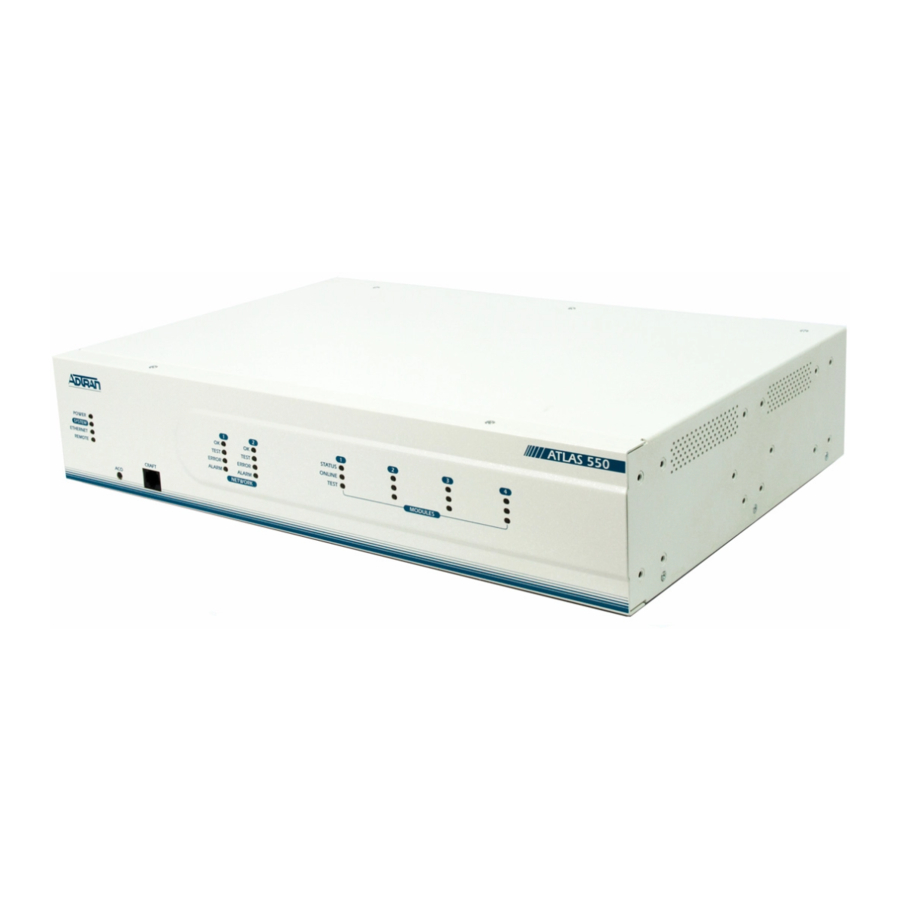
FUNCTIONAL DESCRIPTION The IMUX-56/64 Module installs onto any option module that can be installed into one of the four user slots of the ATLAS 550 chassis. You can view the module status from the ATLAS 550 front panel LEDs (also see Chapter 4 of the ATLAS 550 User Manual). -
Page 13: Physical Description
PHYSICAL DESCRIPTION The IMUX-56/64 Module provides no external interfaces. Other ATLAS 550 components provide both the network and customer interfaces. An internal bus exchanges information between the ATLAS 550 chassis and the IMUX- 56/64 Module. 61200326L1-1A IMUX-56/64 Module User Manual... - Page 14 Chapter 1. Introduction IMUX-56/64 Module User Manual 61200326L1-1A...
-
Page 15: Chapter 2. Installation
ATLAS 550 option module. The IMUX-56/64 module can be attached to any type of ATLAS 550 option module and the resulting assembly can then be installed into any option module slot of the ATLAS 550 chassis. Only an ATLAS 550 option module can be used to carry the IMUX-56/64 module. -
Page 16: Figure 2-1. Atlas 550 Rear Chassis
Instructions for Installing the IMUX-56/64 Module Step Action On the rear of the ATLAS 550 chassis, remove the cover plate covering the slot into which the option module carrying the IMUX- 56/64 module is to be inserted. If theATLAS 550 option module is already in the ATLAS 550 chassis, simply loosen the thumbscrews at both edges of the option module faceplate and slide the module out of the chassis. -
Page 17: Power-Up And Initialization
Chapter 2. Installation POWER-UP AND INITIALIZATION After installing the IMUX-56/64 Module into the ATLAS 550 chassis, the front panel S indicator blinks red, yellow, and green for a time. The TATUS indicator remains solid green when the IMUX-56/64 Module is TATUS ready to use. - Page 18 Chapter 2. Installation IMUX-56/64 Module User Manual 61200326L1-1...
-
Page 19: Chapter 3. Operation
Operation Chapter 3 OVERVIEW You can configure and control the IMUX-56/64 Module from two sources, as shown in Table 3-1. The ATLAS User Manual provides detailed instruc- tions on operating each of the supported management approaches. The re- mainder of this chapter describes the menu items available for managing the IMUX-56/64 Module using the terminal menu. -
Page 20: Menu Access
Chapter 3. Operation MENU ACCESS The ATLAS System Controller automatically detects the presence of the IMUX-56/64 Module when it is installed in the system. To access menus and submenus, use the keyboard arrow keys to scroll to the appropriate row and column;... -
Page 21: Txadd01 Timer
Chapter 3. Operation equipment, it may be necessary to change this time so that it matches TXADD01. TXADD01 Timer Write security: 3; Read security: 5 Specifies the length of time both endpoints wait for additional calls to be connected at the end of negotiation before deciding that the BONDING call has failed. -
Page 22: Modules
Chapter 3. Operation MODULES The following paragraphs (Slt (slot), Type, Menu, Alarm, State, Status, and Rev (revision)) describe the IMUX-56/64 fields (see Figure 3-2). Modules Figure 3-2. Modules Menu Read security: 5 (Slot) Displays the number of available slots in the ATLAS chassis. Slot 0 refers to the ATLAS Base Unit. -
Page 23: Status
Chapter 3. Operation system troubleshooting. If you choose Offline, the module will not be in alarm condition, but will display Offline. Only if State reads Online, can the ATLAS use an installed module for any data bandwidth. Status Read security: 5 Displays status information on the IMUX-56/64 Module. -
Page 24: Imux Menu
Chapter 3. Operation IMUX MENU The IMUX Menu fields include , and (see Figure 3- Info Status Configuration Figure 3-3. IMUX-56/64 Module Submenus Info Read security: 5 Displays module and software information for the option module. Part Number Read security: 5 Displays the IMUX-56/64 Module part number in a read-only field. -
Page 25: Status
Chapter 3. Operation Status Read security: 5 Displays the Status submenus for BONDING resources available on the IMUX-56/64 Module (see Figure 3-4). Figure 3-4. IMUX-56/64 Module Status Menu Status Read security: 5 Indicates the current status of a particular BONDING session. Table 3-4 defines the possible status display values. -
Page 26: Numbchannels
Chapter 3. Operation Read security: 5 NumBChannels Displays the number of bearer channels used in this BONDING session. When the number is displayed in the format X/Y, Y is the number of BONDING resources reserved for this session, and X is the number of calls belonging to this session that are up. -
Page 27: Factory Restore
Chapter 3. Operation Factory Restore Individual IMUX-56/64 Modules do not have independent configurations; there is one configuration for all IMUX-56/64 Modules in an ATLAS. This configuration can be returned to factory default by pressing while the cur- sor is positioned over the BONDING Config submenu, found in the System Config menu. - Page 28 Chapter 3. Operation 3-10 IMUX-56/64 Module User Manual 61200326L1-1A...
-
Page 29: Index
Index accessing menus 3-2 Menu 3-4 Alarm 3-4 menu ATLAS features 3-8 structure 3-1 ATLAS system controller 3-2 modem features 1-2 Modules 3-4 Board Revision 3-6 Bonded Ep 3-8 BONDING 1-1 NumBChannels 3-8 BONDING Config 3-2 BONDING status display values 3-7 offline state 3-4 online state 3-4 Call Stagger 3-3... - Page 30 Index Slt 3-4 terminal menu structure 3-1 State 3-4 tests Status 3-5, 3-7 system self-test 3-8 status messages for Modem-16 3-5 TXADD01 Timer 3-3 System Config 3-2 TXDEQ Timer 3-3 system self-test 3-8, 3-9 TXFA Timer 3-2 TXINIT Timer 3-2 Type 3-4 type menu 3-4 TANULL Timer 3-3...
- Page 31 (888) 4ADTRAN Repair and Return If ADTRAN Technical Support determines that a repair is needed, Technical Support will coordinate with the Customer and Product Service (CAPS) department to issue an RMA number. For information regarding equipment currently in house or possible fees associated with repair, contact CAPS directly...
Need help?
Do you have a question about the ATLAS 550 and is the answer not in the manual?
Questions and answers