ADTRAN ATLAS 550 Quick Manual
Hide thumbs
Also See for ATLAS 550:
- System manual (412 pages) ,
- User manual (262 pages) ,
- Q&a (22 pages)
Advertisement
Quick Links
ATLAS 550 (AC SYSTEM)
Quick Start Guide
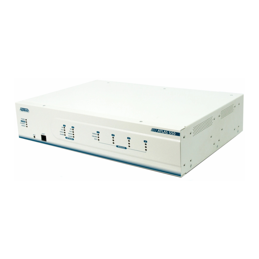
Reviewing the Front Panel
POWER
SYSTEM
ETHERNET
REMOTE
Controller LEDs
ACO
ACO Switch
Connecting to the ATLAS 550
Connecting a VT100 terminal (or VT100 terminal emulator) to the C
interface (on the front panel of the unit) or the C
panel of the unit) allows access to the terminal menus and management
features of the ATLAS 550.
Perform Steps Below in the Order Listed:
1. Configure a VT100 terminal (or terminal emulation software) with the
following settings:
Data Rate:
9600 baud
Data Bits:
8
Parity Bits:
None
If the terminal has a parallel setting, disable it and use serial.
2. Connect one end of the 6" data cable (supplied) into the ATLAS 550 C
or C
I
port. (This connection is RJ-45.) Make the connection to the
ONTROL
N
VT100 terminal as appropriate for your connection. ADTRAN supplies an
RJ-45 to DB-9 adapter for connections to standard DB-9 Communications
(COM) ports.
3. Initiate a terminal session and the L
password is password. (Passwords in the ATLAS 550 are case sensitive.)
Quick Start Guide, 61200305L1-13A, August 2002
Network Module LEDs
1
2
OK
OK
TEST
TEST
ERROR
ERROR
ALARM
ALARM
NETWORK
CRAFT
Craft Interface
RAFT
I
interface (on the rear
ONTROL
N
Stop Bits:
1
Flow Control:
None
screen displays. The default
OGIN
Technical Support 1-888-4ADTRAN (1-888-423-8726)
For more detailed documentation, visit us online at
Option Module LEDs
1
2
STATUS
ONLINE
TEST
Craft Pinout
PIN
NAME
1
GND
2
RTS
3
RXDATA
4
DTR
5
TXDATA
6
CD
7
UNUSED
8
CTS
System Status LEDs
The System Status LEDs display the status of the power supply, controller, and
other system parameters for the ATLAS 550. For a more detailed discussion of
the front panel LEDs, refer to Section 2, Engineering Guidelines, of the ATLAS
550 System Manual.
RAFT
LED
Power
Indicates the status of the power supply
System
Indicates the status of the unit controller and other system parameters.
Ethernet Indicates the status of the ethernet port.
Remote
Indicates whether a user (Telnet or VT100) is logged in to the unit.
P/N 1200305L1
ATLAS 550
3
4
MODULES
DESCRIPTION
Ground - connected to unit chassis
Request to send - flow control
Data received by the ATLAS 550
Data terminal ready
Data transmitted by the ATLAS 550
Carrier detect
—
Clear to send - flow control
Description
Copyright 2002 ADTRAN, All Rights Reserved
www.adtran.com
Advertisement

Related Manuals for ADTRAN ATLAS 550


Summary of Contents for ADTRAN ATLAS 550
- Page 1 If the terminal has a parallel setting, disable it and use serial. the front panel LEDs, refer to Section 2, Engineering Guidelines, of the ATLAS 550 System Manual. 2. Connect one end of the 6” data cable (supplied) into the ATLAS 550 C RAFT or C port.
- Page 2 Connecting Power to the ATLAS 550 UNUSED — The AC powered ATLAS 550 comes equipped with a detachable 8-foot power Clear to send - flow control cord with a 3-prong plug for connected to a grounded power receptacle. Please refer to Section 3, Network Turnup Procedures, of the ATLAS 550 System 10/100BaseT Ethernet Pinout Manual for more detailed instructions.
Need help?
Do you have a question about the ATLAS 550 and is the answer not in the manual?
Questions and answers