Table of Contents
Advertisement
Quick Links
Advertisement
Table of Contents

Related Manuals for ADTRAN Atlas 550


Summary of Contents for ADTRAN Atlas 550
-
Page 1: User Manual
ATLAS 550 User Manual Part Number 1200305L1 61200305L1-1B May 2000... - Page 2 DMS 100 is a registered trademark of Northern Telecom. 5ESS is a registered trademark of AT&T. AT&T is a registered trademark. 901 Explorer Boulevard P.O. Box 140000 Huntsville, AL 35814-4000 (256) 963-8000 © 2000 ADTRAN, Inc. All Rights Reserved. Printed in U.S.A.
- Page 3 Part 68-compliant. See Chapter 2, Installation, for details. If your telephone equipment (ATLAS 550) causes harm to the telephone network, the telephone company may discontinue your service temporarily. If possible, they will notify you in advance.
- Page 4 Affidavit Requirements for Connection to Digital Services • An affidavit is required to be given to the telephone company whenever digital terminal equipment without encoded analog content and billing protection is used to transmit digital signals contain- ing encoded analog content which are intended for eventual conversion into voiceband analog sig- nals and transmitted on the network.
- Page 5 ( ) C. An independent training course (e.g., trade school or technical institution) recognized by the manufacturer/grantee of the equipment used to encode analog signals; or ( ) D. In lieu of the preceding training requirements, the operator(s)/maintainer(s) is (are) under the control of a supervisor trained in accordance with _________ (circle one) above.
- Page 6 The Industry Canada Certification label identifies certified equipment. This certification means that the equipment meets certain telecommunications network protective, operational, and safety requirements. The Department does not guarantee the equipment will operate to the user's satisfaction. Before installing this equipment, users should ensure that it is permissible to be connected to the facil- ities of the local telecommunications company.
-
Page 7: Chapter 10 Dedicated Maps
The ATLAS 550 system consists of the Base Unit, at least one network module, and one or more option modules. (Each network/option module includes its own user manual which contains specific infor- mation about installing, configuring, and testing the option module; insert the option module manuals into this binder.) The ATLAS 550 User Manual provides the information you need to install, configure,... - Page 8 Notes, cautions, and warnings provide other significant information. They are easily identified, as shown below: Menu Items Terminal menus and options are distinguished from regular text by using a bold font and small, uppercase letters. For example, “Use the S Keyboard Commands The keyboard keys used to carry out commands are highlighted in bold.
- Page 9 Customer or a third party (including, but not limited to, loss of data or information, loss of profits, or loss of use). ADTRAN is not liable for damages for any cause whatsoever (whether based in contract, tort, or otherwise) in excess of the amount paid for the item.
-
Page 11: Table Of Contents
Dedicated and Switched Connection Maps in a Single Platform... 1-4 WAN Overbooking ... 1-4 Digital Access Cross-Connect System (DACS) ... 1-4 Flexible Network Management and Maintainability ... 1-5 ATLAS 550 Features ... 1-5 Chapter 2 Installation ... 2-1 Inspecting the ADTRAN Shipment... 2-1 Contents of ADTRAN Shipments ... - Page 12 Slot ... 6-4 Port ... 6-4 Event Description ... 6-4 Clear System Event Log ... 6-5 Ethernet Port ... 6-5 Clear System LED ... 6-5 System Temperature Alarms ... 6-5 System Power Alarms ... 6-5 ATLAS 550 User Manual 61200305L1-1...
- Page 13 Current Time/Date ... 6-14 Auto Daylight Savings ... 6-14 Access Passwords ... 6-15 Instructions for Adding/Deleting Passwords... 6-15 Label ... 6-16 Password ... 6-16 Access Rights ... 6-16 Active ... 6-16 Licenses ... 6-16 61200305L1-1 ATLAS 550 User Manual Table of Contents xiii...
- Page 14 Reset Stats ... 6-24 Start/Stop ... 6-24 Reboot System ... 6-24 Factory Default System ... 6-24 Chapter 7 Module Terminal Menus ... 7-1 Overview ... 7-1 Modules ... 7-1 Slt ... 7-2 Type ... 7-2 Menu ... 7-2 ATLAS 550 User Manual 61200305L1-1...
- Page 15 Sublink ... 8-11 Endpnt Count ... 8-12 Endpnts Sort ... 8-12 Packet Cncts... 8-13 From: PEP ... 8-13 Sublink ... 8-13 To: PEP ... 8-13 Sublink ... 8-13 Protocol ... 8-13 Config ... 8-14 61200305L1-1 ATLAS 550 User Manual Table of Contents...
- Page 16 Interface ... 9-4 Local ... 9-4 EN0 IP ... 9-4 Endpoint Name ... 9-4 Used ... 9-5 Clr ... 9-5 Flags ... 9-5 Hops ... 9-5 TTL ... 9-5 Interfaces ... 9-5 Network Name ... 9-5 ATLAS 550 User Manual 61200305L1-1...
- Page 17 Dedicated Maps ... 10-1 Overview ... 10-1 Using Dedicated Maps with Frame Relay... 10-2 Activate Map ... 10-2 Auto ... 10-2 Maps 1 through 5 ... 10-2 Current Map ... 10-2 61200305L1-1 ATLAS 550 User Manual Table of Contents xvii...
- Page 18 Data 56K, Data 64K, Audio, Speech ... 11-8 Ifce Config ... 11-8 Global Param ... 11-9 End of Number Timeout ... 11-9 Area Code ... 11-9 Nbr Complete Templates ... 11-9 Number Type Templates ... 11-9 xviii ATLAS 550 User Manual 61200305L1-1...
- Page 19 Outgoing Caller ID ... 11-19 Source ID ... 11-19 Swap ANI/DNIS ... 11-19 Dual T1/PRI Module: User Termination/RBS... 11-20 First DS0 ... 11-20 Number of DS0s ... 11-20 DS0s Available ... 11-20 Signaling Method ... 11-20 61200305L1-1 ATLAS 550 User Manual Table of Contents...
- Page 20 Sig ... 11-29 In#Accept ... 11-29 Out#Rej ... 11-29 Ifce Config ... 11-29 PktVoice ... 11-31 Slot/Svc ... 11-31 Port/PEP ... 11-31 Sig ... 11-31 In#Accept ... 11-31 Out#Rej ... 11-31 Ifce Config ... 11-31 ATLAS 550 User Manual 61200305L1-1...
- Page 21 Menu Bar... 14-3 File ... 14-3 Display... 14-4 Log Files ... 14-4 Erase Log Files ... 14-4 Define RED Events ... 14-4 Properties ... 14-4 Clear RED Events ... 14-4 Help... 14-4 61200305L1-1 ATLAS 550 User Manual Table of Contents...
- Page 22 Local Echo ... 14-10 AutoRepeat ... 14-10 Capture ... 14-10 Help... 14-10 Contents ... 14-10 About ... 14-10 TFTP Server Utility ... 14-10 Server ... 14-11 Enable ... 14-11 Disable ... 14-11 Abort ... 14-11 xxii ATLAS 550 User Manual 61200305L1-1...
- Page 23 Appendix B OSI Model and Frame Relay Technology Overview...B-1 Appendix C Frame Relay Examples ... C-1 Appendix D Router Examples ... D-1 Appendix E Troubleshooting...E-1 Appendix F Acronyms and Abbreviations ... F-1 Appendix G Glossary ... G-1 Index ...Index-1 61200305L1-1 ATLAS 550 User Manual Table of Contents xxiii...
- Page 24 Table of Contents xxiv ATLAS 550 User Manual 61200305L1-1...
- Page 25 Figure 10-4. ATLAS 550 with Modules Installed for Example 2 ......10-7 Figure 10-5.
- Page 26 ATLAS to Support Packet Data Configuration ....... . . C-1 Figure C-2. IP Routing Network with ATLAS 550 as the Central-Site Router ....C-2 Figure C-3.
- Page 27 ATLAS 550 Configured for the Router Option ....... . .
- Page 28 List of Figures xxviii ATLAS 550 User Manual 61200305L1-1...
- Page 29 ATLAS 550 Front Panel Description ........
- Page 30 Table B-3. Annex A and Annex D DLCI Assignments ........B-6 ATLAS 550 User Manual...
-
Page 31: Chapter 1 Introduction
With the appropriate modules installed, the two main functions of the ATLAS 550 are to act as an Access Router and an Access Switch. -
Page 32: Frame Relay/Router
Chapter 1. Introduction Access Router As an Access Router, the ATLAS 550 combines the functions of a T1 CSU/ DSU, an intelligent channel bank, a T1 Multiplexer, and DACS into a single platform. The ATLAS 550 is ideal for point-to-point configurations or access to public networks. -
Page 33: Access Switch
Router Router The ATLAS 550 router uses the Ethernet port to transmit local area network (LAN) traffic over the wide area network (WAN) to a remote LAN. By inte- grating the router into the network access device, you benefit from the cost savings of not requiring an external router. -
Page 34: Dedicated And Switched Connection Maps In A Single Platform
550. Dedicated and Switched Connection Maps in a Single Platform The ATLAS 550 allocates dedicated bandwidth according to any of up to five unique connection maps. Any DS0 on any T1 circuit can be mapped to any other DS0 on up to four T1 circuits in the system. Dedicated connection maps can be manually invoked or automatically implemented based on the time of day and day of the week. -
Page 35: Flexible Network Management And Maintainability
You can remotely download software using TFTP or XMODEM. The ATLAS 550 front panel contains an extensive array of LEDs for alarm and status information pertaining to the system and the individual modules. Several test capabilities allow you to diagnose the health of your T1, PRI, or BRI circuits without additional test equipment. - Page 36 DTE running frame relay to ATLAS. • Performs voice compression/decompression (G.723.1) and interfaces to either a Private Branch Exchange (PBX) or the Public Switched Tele- phone Network (PSTN). (This feature requires an additional option module, the VCOM Module—P/N 1200312Lx.) ATLAS 550 User Manual 61200305L1-1...
-
Page 37: Chapter 2 Installation
ADTRAN Technical Support (see the last page of this manual). If possible, keep the original shipping container for return- ing the ATLAS 550 for repair or for verification of damage during shipment. Contents of ADTRAN Shipments Your ADTRAN shipment includes the following items: •... -
Page 38: Grounding Instructions
8 ring terminal and should be fastened to the ground- ing lug provided on the rear panel of the equipment. The ring terminal should be installed using the appropriate crimping tool (AMP P/N 59250 T-EAD Crimping Tool or equivalent.) ATLAS 550 User Manual 61200305L1-1... -
Page 39: Reviewing The Rear Panel Design
As shipped, the ATLAS 550 is set to factory default conditions. After install- ing the Base Unit and any option modules, the ATLAS 550 is ready for pow- er-up. To power-up the unit, ensure that the unit is properly connected to an appropriate power source and turn on the unit using the on/off switch on the rear panel. -
Page 40: Control/Chain In Port
Port Control/Chain In Port The Control/Chain In port (EIA-232) connects to a computer or modem or to another ATLAS 550 Base Unit. The control port input provides the follow- ing functions: • Accepts EIA-232 input from a PC or a modem for controlling the ATLAS 550. -
Page 41: Ethernet Connection
Control/Chain Out Port The Control/Chain Out port (RJ-48C) connects to another ATLAS 550 Chain In connector. The Control/Chain Out port output provides the following: • EIA-232 output to chain control to other ADTRAN equipment, such as a TSU 120. •... -
Page 42: External Alarm Relay Monitor Connection
This connection alerts the user when a selected external alarm condition ex- ists. This connection could be used to monitor a UPS with dry contacts or an- other ATLAS 550. The two-pin, removable terminal block connects with external wiring. To make the appropriate connections, remove the block, connect wiring as needed, and return the terminal block to the connector socket. -
Page 43: Network Connection
Table 2-5 shows the pinout for the External Alarm Relay connector. Network Connection The ATLAS 550 provides two Network Interface Slots that allow different types of interfaces to be used. Currently only a T1 Network Interface is avail- able. In the remainder of this manual, discussions about the Network Inter- face Module refer to the T1 Network Interface Module. -
Page 44: Frame Relay Specifications
Bantam test jacks provide intrusive test capability Bantam test jacks provide a bridged access jack for nonintrusive UNI (user-to-network interface) NNI (network-to-network interface) ANSI T1.617-D (Annex D) ITU-T Q.933-A (Annex A) LMI (Group of four) Auto ATLAS 550 User Manual DESCRIPTION 61200305L1-1... -
Page 45: Installing Option Modules
SNMP support - MIB II Option Slots Figure 2-2 shows the option slot numbering designation as viewed from the rear of the ATLAS 550. The functionally identical option slots only accept ATLAS 550 option modules. INSTALLING OPTION MODULES After installing the ATLAS 550 Base Unit and connecting the required ca- bles, you can install your choice of option modules. - Page 46 Chapter 2. Installation 2-10 ATLAS 550 User Manual 61200305L1-1...
-
Page 47: Chapter 3 Operation
Operation Chapter 3 OVERVIEW To fully operate the ATLAS 550, you must connect to the terminal menus us- ing VT-100 terminal emulation or a Telnet session. The following sections provide an overview of these methods of operating the ATLAS 550. - Page 48 See Access Passwords on page 6-15 for details. After your password is accepted, define the IP Address of the ATLAS 550 to which you want to connect. The following Step/Action chart describes this process.
-
Page 49: Starting A Telnet Session
USING TELNET To connect to the ATLAS 550 via Telnet, you must define the IP address, set the subnet mask, and, typically, set the default gateway IP address. Starting a Telnet Session When you begin the Telnet session, you will be prompted for a password. - Page 50 Chapter 3. Operation ATLAS 550 User Manual 61200305L1-1...
-
Page 51: Chapter 4 Using The Front Panel
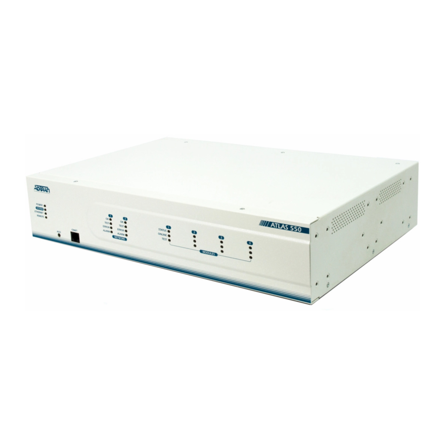
The front panel contains the Alarm Cut-off (ACO) switch, the CRAFT port, and the controller and module status LEDs. The LEDs provide visual infor- mation about the ATLAS 550 Base Unit and any option module that may be installed. Figure 4-1 identifies the ACO switch, the CRAFT port, and the LEDs. -
Page 52: Front Panel Leds
Use the CRAFT port to configure the system via an EIA-232 connection. The CRAFT port provides the same functions and operations as the Control In port located on the rear panel of the ATLAS 550. The connector type is shown below, and Table 4-1 gives the CRAFT port pinout (see also CRAFT Port on page 4-3 in Table 4-2). -
Page 53: Table 4-2. Atlas 550 Front Panel Description
Feature Controller Status LEDs Displays the general status of the entire ATLAS 550. (See also Table 4-3 on page 4-4.) Power Indicates the unit is on or off. System Indicates the status of the system. Ethernet Indicates the status of the ethernet port. -
Page 54: Table 4-3. Atlas 550 Leds
OK (green) Status Test (yellow) Error (flashing red) Indicates an error such as BPV (bipolar violation), Alarm (red) Table 4-3. ATLAS 550 LEDs Indicates that... The unit is on. The unit is off. Physical link is up. Indicates activity on the LAN. - Page 55 Module Test Yellow (solid) 61200305L1-1 Chapter 4. Using the Front Panel Table 4-3. ATLAS 550 LEDs (Continued) Indicates that... One or both modules (in the case of a Resource Module) are OK. • One or both modules (in the case of a Resource Module) have been set offline by the user.
- Page 56 Chapter 4. Using the Front Panel ATLAS 550 User Manual 61200305L1-1...
-
Page 57: Chapter 5 Navigating The Terminal Menus
Chapter 5 TERMINAL MENUS WINDOW The ATLAS 550 uses a multilevel menu structure that contains both menu items and data fields. All menu items and data fields display in the terminal menu window, through which you have complete control of the ATLAS 550 (see Figure 5-1). -
Page 58: Menu Path
The top line of the terminal menu window, the menu path, shows the ses- sion’s current position (path) in the menu structure. For example, in Figure 5-1 on page 5-1 the cursor is on the S menu; therefore, the menu path reads ATLAS 550/M ULES ODULE... -
Page 59: Additional Terminal Menu Window Features
Underlined field Additional Terminal Menu Window Features The following features are located across the bottom of the window: Describes the status of the ATLAS 550 base unit. Tool Tip Provides a brief description of the currently selected (highlighted) field. Slot Status Displays status information, such as OK, WARN (warning), or ALRM (alarm), about slots 1 through 4. -
Page 60: Navigating Using The Keyboard Keys
Press tivate a pop-up screen listing the navigation keystrokes. ) Displays information about selected commands (see Figure 5-3). Figure 5-3. Sample Extended Help Window Figure 5-4. Navigation Help Window ATLAS 550 User Manual to ac- Ctrl-Z 61200305L1-1... -
Page 61: Session Management Keystrokes
This option should only be necessary if the display picks up incorrect characters. 61200305L1-1 Chapter 5. Navigating the Terminal Menus , and you jump back to the screen that was ATLAS 550 User Manual Press this key... Arrows Enter Escape... -
Page 62: Configuration Keystrokes
ODULES # field in connection list, press EDICATED connection list, EDICATED to activate a help screen that displays the keystrokes for navigat- ATLAS 550 User Manual Press this key... > < a pop-up help Ctrl-A, 61200305L1-1... -
Page 63: Chapter 6 System Control Terminal Menus
To do this... Review and monitor general system information for the ATLAS 550. System Info on page 6-2. Review and monitor system status for the ATLAS 550. Set up the operational configuration for the ATLAS 550. -
Page 64: System Info
Write security: 3; Read security: 5 YSTEM Provides a user-configurable text string for the name of the ATLAS 550. This name can help you distinguish between different installations. You can enter up to 40 alpha-numeric characters in this field, including spaces and special characters (such as an underbar). -
Page 65: Firmware Revision
ATLAS 550 system. You can enter up to 40 alpha-numeric char- acters in this field, including spaces and special characters (such as an underbar). -
Page 66: Event Description
Displays a description of the event. VENT ESCRIPTION Figure 6-2. System Status Menu ) displays the severity of the event. The possible categories are AJOR INOR ARNING ORMAL ATLAS 550 User Manual , and I . You can specify VENT OGGING 61200305L1-1... -
Page 67: Exit
Indicates which timing source (primary or backup) is currently being used OURCE by ATLAS 550 and if ATLAS 550 is locked onto this source. If the display does not indicate locked, the ATLAS 550 does not have a valid source of timing and cannot reliably transfer data. -
Page 68: Configuration
Write security: 4; Read security: 5 Selects the mode for resetting statistics—M NALOG AILED ). Data displayed in this table is dependent on the Atlas 550 configu- One HDLC resource is used by each PRI or each Packet Endpoint. AVAILABLE ORMT... - Page 69 ORMT Write security: 4; Read security: 5 Selects the mode for resetting statistics—M , or W AILY EEKLY Request to send. Clear to send. Data terminal ready. Data carrier detect. ATLAS 550 User Manual PRI, U RBS). or %. ANUAL...
-
Page 70: Primary Timing Source
ACKUP IMING Selects the secondary timing source. You can select either OURCE port from one of the installed modules. ATLAS 550 uses the backup timing source if the primary timing source goes into alarm. The B OURCE ADLP A Write security: 2; Read security: 5... -
Page 71: Default Gateway
255, separated by periods. This value is set to 0.0.0.0 by default. This part of the destination IP address is used along with the ATLAS 550 IP address to determine which nodes must be reached through the default IP gateway. -
Page 72: Modem Initialization String
SNMP Write security: 3; Read security: 5 Provides a way to configure SNMP access for the ATLAS 550. For detailed information on SNMP, refer to SNMP Management on page 13-1. The follow- ing options are available for review and editing: SNMP A Write security: 3;... -
Page 73: Trap Transmission
SNMP trap. (Refer to the ATLAS 550 MIB for a listing of all traps and their severity levels.) You can set the following threshold levels for the... -
Page 74: Ds1 Current Perf Thresholds
T-W and append the C ATCH ES T HRSH SES T HRSH SEFS T HRSH UAS T HRSH CSS T HRSH PCV T (D4) HRSH PCV T (ESF) HRSH LES T HRSH ATLAS 550 User Manual with OMMUNITY 61200305L1-1... - Page 75 Chapter 6. System Control Terminal Menus LCV T HRSH ES T HRSH SES T HRSH SEFS T HRSH UAS T HRSH CSS T HRSH PCV T (D4) HRSH PCV T (ESF) HRSH LES T HRSH ATLAS 550 User Manual 6-13...
-
Page 76: Event Logging
OGGING Write security: 3; Read security: 5 Sets the system event severity level threshold for each of the ATLAS 550 system event types. Whenever a system event occurs, that event is logged if the event’s severity level is equal to or more severe than the event type’s current threshold setting. -
Page 77: Access Passwords
All menu items are protected by passwords of varying security lev- els. By assigning different passwords to different security levels, the ATLAS 550 system administrator can control which users can change vari- ous menu items. You can assign multiple passwords at the same access level. This way, dif- ferent users with the same access privileges can have different passwords. -
Page 78: Password
This field may not be applicable for a given feature—if it is not, this field is blank. 6-16 If you lose or forget the ATLAS 550 system administrator password, contact ADTRAN technical support (see last page of this manual) for help in resetting the password. -
Page 79: Status
TATUS key. LARM ELAY Write security: 3; Read security: 5 Clears the Alarm Relay located on the rear panel of the ATLAS 550. ESET Write security: 3; Read security: 5 LARM ELAY Defines which threshold sets the Alarm Relay. If an alarm occurs that is HRESHOLD greater than or equal to the threshold selected, the Alarm Relay will set. -
Page 80: Module Slot
TFTP S Write security: 1; Read security: 5 Configures the IP address of the TFTP Server on which the update file resides. ATLAS 550 uses this field to locate the network server on which the update file resides. TFTP S Write security: 1;... - Page 81 Indicates the time of the previous update. (see Table 12-1 on page 12-5). PDATE TATUS Following a successful update, the field reads If an update was unsuccessful, the appropriate ATLAS 550 User Manual ESTART ATE AND is only available for the TATUS is set...
-
Page 82: Subnet Mask
Write security: 3; Read security: 5 ONFIG RANSFER Used only with TFTP transfers. Sends a file containing the ATLAS 550 con- figuration to a file on a TFTP Server using the TFTP protocol through the Ethernet port. C ration as a backup file, so you can use the same configuration with multiple ATLAS 550 units. -
Page 83: System Selftest
YSTEM TILIZATION Write security: 0; Read security: 0 Displays statistics related to the ATLAS 550 internal operating system. Please check with ADTRAN Technical Support before attempting to use this menu. Write security: 3; Read security: 5... -
Page 84: Selftest
; to cancel the self-test, press is currently being run. See View Selftest Log ELFTEST Index number of the log. Time and date of the log entry. ATLAS 550 slot number. ATLAS 550 port number. Event description. Shows Pass/Fail results. ATLAS 550 User Manual , or any other installed Figure 6-6. -
Page 85: Ping
Verifies memory associated with the real time clock. Verifies memory associated with mapping TDM bandwidth. Verifies dynamic RAM used for program execution. Verifies each HDLC controller used for frame relay or PRI. Only one ping session can be active at a time. ATLAS 550 User Manual 6-23... -
Page 86: Round Trip Min
Write security: 0; Read security: 0 EBOOT YSTEM Reboots the ATLAS 550. When you select this command, the following mes- sage displays: **WARNING ** This will reboot the entire system! Press reboot the system, or Write security: 0; Read security: 0... -
Page 87: Chapter 7 Module Terminal Menus
Individual option module menus are described in the applicable module manuals. The ATLAS 550 system controller automatically detects the presence of modules when they are installed in the system. To view the menus for the installed modules via the terminal menu, use the arrow keys to scroll to the... -
Page 88: Type
Read security: 5 Displays the type of test the ATLAS 550 or selected module is executing. To initiate a test, select the M have access to the screen that allows you to set up and initiate tests. See Test on page 7-7 for details. -
Page 89: Modules Menu (T1Network Interface Module)
FFLINE FFLINE ESPONSE UPPORTED Read security: 5 Displays the hardware revision of the ATLAS 550 and other installed mod- ules. Modules Menu (T1Network Interface Module) This section provides detailed information on the M menus. M tus of various options, change the configuration for general parameters, and initiate tests. -
Page 90: Info
(Receive Level) Indicates the strength of the signal re- EVEL ceived on the port. Inactive Active call on this DS0 Active D channel DS0 Maintenance DS0 Dedicated DS0 Off-hook detected Ringing detected ATLAS 550 User Manual Table 7-1. Alarm Types 61200305L1-1... -
Page 91: Performance: 15 Min
Severely Errored Frame Seconds. Loss of Frame Count. Controlled Slip Seconds. Unavailable Seconds. Line Code Violations. Path Code Violations. Line Errored Seconds. menu, the performance data for the previous ERFORMANCE ATLAS 550 User Manual Chapter 7. Module Terminal Menus when the Enter... -
Page 92: Configuration
ANSI T1.403. This is a line loopback. ULSE Write security: 3; Read security: 5 When O inserts a one (1) when needed to maintain ones at 12.5%. ENSITY , the ATLAS 550 monitors for ones (1s) density violations and ATLAS 550 User Manual is disabled 61200305L1-1... -
Page 93: Test
Sends ANSI line loopback code. Requires ESF mode. Sends ANSI payload loopback code. Requires ESF mode. Sends line loopback using inband code. Framed ones Framed zeros Pseudorandom pattern with suppression of excess zeros ESULTS ATLAS 550 User Manual Chapter 7. Module Terminal Menus... - Page 94 Chapter 7. Module Terminal Menus ATLAS 550 User Manual 61200305L1-1...
-
Page 95: Chapter 8 Packet Manager
The P ACKET points. A packet endpoint is a virtual port within the ATLAS 550 into which a specified physical port (a T1 or an Nx56/64) terminates its data for further routing by the system. All packet services, including the ATLAS 550 frame relay, must have defined packet endpoints. -
Page 96: Packet Endpnts
Aborts CRC Error Octet Align Length Error EA Violation Inactive DLCI Invalid DLCI Figure 8-2. Packet Manager Menu Tree ATLAS 550 User Manual Tx Pckts Rx Pckts State Changes Signaling Errors Signaling Timeout Full Status Tx Full Status Rx Link Integrity Status Tx... -
Page 97: Prot
), the signaling type (S URRENT (also see Config on page 8-6). NKNOWN ETWORK A, A NKNOWN NNEX NNEX ATLAS 550 User Manual Chapter 8. Packet Manager ONFIG NDPNT OUNT ), the signal- ), the signaling state (S ). The following sections dis- ACKET... -
Page 98: Performance
(also see Dedicated Maps on page 10-1). If the port is a chan- (endpoint name), P ROTOCOL (also see Config on page 8-6). ACKET NDPNTS ONFIG ATLAS 550 User Manual in this field map (also ACKET NCTS , and S TATS... - Page 99 Indicates if this particular sublink (PVC) has been defined as active by a full status poll. 61200305L1-1 HANGES RRORS IMEOUTS menu (also see Config on page 8-6). ACKET NDPNTS ONFIG TATUS TATUS TATUS TATUS OUNTERS ACKETS ACKETS OUNTERS ACKET ATLAS 550 User Manual Chapter 8. Packet Manager (also see Config on NDPNTS ONFIG...
-
Page 100: Protocol
Defines whether this packet endpoint acts as the network or user side of the UNI or as an NNI. OUNT ISCARD OUNT OUNT OUNTERS One HDLC resource is used by each PRI or each Packet Endpoint. ATLAS 550 User Manual configures this RAME ELAY 61200305L1-1... - Page 101 If the number of polls reaches N392 in any N393 period, the link will be declared down. When N393 good polls are received, the link will be declared active again. (T392) ESPONSE IMEOUT ATLAS 550 User Manual Chapter 8. Packet Manager...
-
Page 102: Sublinks
If the number of bad polls reaches N392 in any N393 period, the link will be declared down. When N393 good polls are received, the link will be declared active again. rate defines by what amount this virtual circuit is URST ATLAS 550 User Manual 61200305L1-1... -
Page 103: Table 8-1. Suggested Fragmentation Values Based On The Pvc Cir
All packets on this PVC will get a numbered tag so that ADTRAN IQ products can detect lost packets in the frame relay network. Turn this option ON only if there is an ADTRAN IQ-capable product on the other end of the PVC. -
Page 104: Sublinks Example
HROUGH IAGNOSTIC ACKETS Used when the ATLAS 550 is acting as a frame relay switch. Trans- mits a diagnostic packet out the packet endpoint connected to this DLCI, if a diagnostic packet is received on this packet endpoint. DLCI QOS ATLAS 550 User Manual . -
Page 105: Protocol
Switched packet connection in the dial plan. Used by one or more packet switch connections or packet voice entries. Packet voice entries are in either the D ATLAS 550 User Manual Chapter 8. Packet Manager Table 8-2. Usage Characters or the... - Page 106 550). Displays the total number of packets lost in the transmit direction (trav- eling from the ATLAS 550 to the remote ADTRAN frame relay device). Displays the minimum round trip delay for the current test period. Displays the maximum round trip delay for the current test period.
-
Page 107: Protocol
R available in this pull-down menu. The router is the internal the ATLAS 550 router and can be used multiple times within the P Write Security: 3; Read Security: 5... -
Page 108: All Sublinks
IQ provides information about frame relay activity. Statistical ELAY , 96 ] when re-enabled. DAYS INTS , and S NABLE UBLINKS UBLINKS ISABLE ATLAS 550 User Manual ACKET UBLINK NDPT UBLINK , and V IQ S TATISTICS to configure the individual , pressing disables IQ statis-... -
Page 109: Config
Identifies resources used by IQ statistics storage. A PIV is a port or PVC per interval. The ATLAS 550 can track up to 10,000 PIVs. Think of it as a resource meter. The PIV number is derived from the M NTERVALS Write security: 2;... - Page 110 The number of PVC signaling frames received with protocol violations. IGNAL The number of PVC signal time-outs. Either T391 seconds elapsed without receiving a response to a poll or T392 seconds elapsed without receiving a poll. 8-16 RROR ATLAS 550 User Manual or D submenus fol- NTERVAL 61200305L1-1...
-
Page 111: Crc Error
I follow: LINK RAMES The number of frames the PVC received for the interval or day. 61200305L1-1 TATUS RAME RROR LIGN RROR DLCI DLCI ATLAS 550 User Manual Chapter 8. Packet Manager or D submenus of S NTERVAL 8-17... - Page 112 The number of BECNs the PVC has transmitted for the interval or day. The number of DEs the PVC has received for the interval or day. The number of DEs the PVC has transmitted for the interval or day. 8-18 ATLAS 550 User Manual 61200305L1-1...
- Page 113 RAME ELAY EASUREMENT RAME ELAY EASUREMENT ELAY EASUREMENT TATE HANGE ATLAS 550 User Manual Chapter 8. Packet Manager (see page 8-9) on the PVC. is E (see page 8-10) for NABLED is E (see page 8-10) NABLED is E (see page 8-10)
- Page 114 Chapter 8. Packet Manager 8-20 ATLAS 550 User Manual 61200305L1-1...
-
Page 115: Chapter 9 Router
Router Chapter 9 OVERVIEW The ATLAS 550 router provides remote connectivity of LANs within an ATLAS 550—from LAN-to-WAN connection or from WAN-to-WAN connection. Internet Protocol (IP) routing is performed at layer 3 of the Open System In- terconnection (OSI) model. (See Appendix B, OSI Model and Frame Relay Technology Overview, for a discussion of the OSI model.) The routing process... -
Page 116: Reset Stats
Reset Stats Start/Stop Disable Enable Standard Specified UDP Port 1 UDP Port 2 UDP Port 3 Figure 9-1. Router IP Menu Tree ATLAS 550 User Manual Protocol None Method Split Horizon Poison Reverse Updates Triggered Periodic Authentications (V2 only) V2 Secret... -
Page 117: Ip Address
IP routes (see Figure 9-2). manages static IP routes. You can create, modify, OUTES , this static route is advertised over all interfaces on which a ATLAS 550 User Manual Chapter 9. Router Figure 9-2. IP Routes Menu , this is a... -
Page 118: Mac Address
Sent directly to the ATLAS 550 router. OCAL EN0 IP The ATLAS 550 Ethernet port. The DLCI number. NDPOINT displays the contents of the ATLAS 550 Address Res- ACHE displays the contents of the ATLAS 550 route table. All ATLAS 550 User Manual 61200305L1-1... -
Page 119: Used
ATLAS 550 router. These include the Ethernet and frame relay DLCIs connected in the P ETWORK Read security: 5 Displays the name of the interface connected to the ATLAS 550 router. The options are listed below: EN0 IP The ATLAS 550 Ethernet port. -
Page 120: Far-End Address
The ATLAS 550 always responds to Inverse ARP requests with its IP address for the requested DLCI. The ATLAS 550 sends Inverse ARP packets in order to determine the IP ad- NABLE dress on the other end of the virtual circuit. If the Inverse ARP packet is re- sponded to, a route is placed in the IP route table. - Page 121 “poisoned” with an infinite route metric. ERIODIC RIP advertisements are periodically transmitted. RIGGERED RIP advertisements are transmitted only when new routes are learned, and learned routes do not age. ATLAS 550 User Manual Chapter 9. Router ROTOCOL ETHOD...
-
Page 122: Ip Address
0 to 255, separated by periods. This value is set to 0.0.0.0 by default. Contact your LAN administrator for the appropriate ad- dress. is visible only if RIP V2 is E NABLED This parameter is global throughout the ATLAS 550. Changes here affect all router interfaces. ECRET on the Enter... -
Page 123: Round Trip Min
255, separated by periods. This value is set to 0.0.0.0 by default. This part of the destination IP address is used along with the ATLAS 550 IP address to determine which nodes must be reached through the default IP gateway. -
Page 124: Reset Stats
Source-Routed via the host). Default TTL The default value inserted into the Time-To-Live field of the IP header of datagrams originated at this ATLAS 550, whenever a TTL value is not supplied by the transport layer protocol. InReceives The total number of input datagrams received from interfaces, including those received in error. - Page 125 ATLAS 550. FragFails The number of IP datagrams that have been discarded because they needed to be fragmented at this ATLAS 550 but could not be, e.g., because their “Don't Fragment” flag was set. 61200305L1-1 Table 9-1. IP Statistics (Continued)
-
Page 126: Icmp
Note that this counter includes all those counted by icmpOutErrors. OutErrors The number of ICMP messages which this ATLAS 550 did not send due to problems discovered within ICMP such as a lack of buffers. This value should not include errors discovered outside the ICMP layer such as the inability of IP to route the resultant datagram. -
Page 127: Table 9-3. Tcp Statistics
UBOUND quantity described in RFC 793. MaxConn The limit on the total number of TCP connections the ATLAS 550 can support. In entities where the maximum number of connections is dynamic, this object should contain the value “-1.”... -
Page 128: Table 9-4. Udp Statistics
Total number of times the ATLAS 550 went into the Fast Cache and successfully retrieved an IP address. Misses Total number of times the ATLAS 550 went into the FastCache and failed to retrieve an IP address. Clear Clears the accumulated statistics. -
Page 129: Relay Table
ELAY Write security: 2; Read security:5 Configures the ATLAS 550 as a UDP (User Datagram Protocol) relay agent to relay UDP broadcasts to a specified server IP address. UDP broadcasts received on a given port may be relayed to, at most, one server. - Page 130 Chapter 9. Router 9-16 ATLAS 550 User Manual 61200305L1-1...
-
Page 131: Figure 10-1. Dedicated Maps Menu Tree
OVERVIEW The D EDICATED two ports in the ATLAS 550 Base Unit. This chapter describes the D menu (see Figure 10-1). These options are module-dependent; that is, the menu items available depend on the module selected. In addition, step- by-step instructions are provided for setting up a sample dedicated map (see Creating A Dedicated Map on page 10-7). -
Page 132: Using Dedicated Maps With Frame Relay
Move the arrow keys to highlight the A press E NTER Move the arrow key to highlight the map of choice from the pop- up menu list and press E NTER ATLAS 550 User Manual or the EDICATED “nail” the EDICATED associates a phone number with... -
Page 133: Create / Edit
Some of the options available in this submenu change depending on the type of modules selected in the FROM or TO fields. Enter The ATLAS 550 does not support frame relay at a DS0 rate of 56K. ATLAS 550 User Manual Chapter 10. Dedicated Maps... - Page 134 Defines the data rate per DS0. If FROM S DS0 must be set. You can choose from 64 kbps or 56 kbps. 10-4 The ATLAS 550 does not support frame relay at a DS0 rate of 56K. option. You must input the following information—based on ELECTION .
- Page 135 EDICATED ONDITIONING ERVICE Trunk conditioning only applies to RBS T1s in the dedicated map. E&M, V LS/GS U OICE OICE SW56, and C ERMINATION ATLAS 550 User Manual Chapter 10. Dedicated Maps OICE ERMINATION OICE —depending on the USTOM 10-5...
-
Page 136: Activate Map
Defines to the ATLAS 550 the signaling bits being used on the trunk. Fault signaling is only visible when RBS is turned on. Defines to the ATLAS 550 the value to set in the data field for outgoing DS0s when a trouble condition exists. -
Page 137: Figure 10-3. Trunk Conditioning
Example 2 (see Figure 10-5) contains three T1s (T1-A, T1-B, T1-C) that sup- port dedicated bandwidth from three remote sites. Each remote T1 includes DS0s for voice (1-8) and data (9-24). At the central site (the ATLAS 550), each 61200305L1-1... -
Page 138: Figure 10-5. Overview Of Dedicated Map Example
Dual V.35: Slot 2/Port 1 9-24; RBS Off V.35 B Dual V.35: Slot 2/Port 2 9-24; RBS Off V.35 C Dual V.35: Slot 3/Port 1 ATLAS 550 User Manual T1-D: 1-24 Voice V.35 A: Data V.35 B: Data External Router V.35 C: Data DS0s 1-8;... - Page 139 . Press to confirm paste (see Figure 10-6 on page 10-9). Assign Dual Nx 56/64 cards (V35Nx-2) to Slots 2 and 3. Figure 10-6. T1/PRI Configuration Menu for Example 2 ATLAS 550 User Manual Chapter 10. Dedicated Maps ONFIGURATION 10-9...
-
Page 140: Figure 10-7. Data Connections
Paste this information onto a new connection line by positioning the cursor over the index number of the new connection, and pressing Modify these connection lines to complete the connections for data (see Figure 10-7). ATLAS 550 User Manual EDICATED REATE field, C ONNECTS as N1) T1/PRI-1. - Page 141 # or when you move the cursor onto another connection line. Figure 10-8. Completed Dedicated Map for Example 2 ATLAS 550 User Manual Chapter 10. Dedicated Maps . For Voice A, ONFIG...
- Page 142 Chapter 10. Dedicated Maps 10-12 ATLAS 550 User Manual 61200305L1-1...
-
Page 143: Chapter 11 Dial Plan
(see Connecting Packet Endpoints in Frame Relay on page 11-28). The D parameters as well as individual parameters for each ATLAS 550 port han- dling a switched call. The individual ports are separated into two port types: network and user. Network ports terminate a connection from the Network. -
Page 144: Figure 11-2. Dial Plan Menu Tree
Data 56K Audio Speech Treat Call As Reject Number Data 64K Data 56K Audio Speech Pattern Prefix Pattern Number Type DTMF Figure 11-2. Dial Plan Menu Tree ATLAS 550 User Manual and SIG. and SIG. Local National International Private Unknown 61200305L1-1... -
Page 145: Network Term
ISDN interface. This selection is only necessary if a T1/PRI is selected as the Write security: 3; Read security: 5 CCEPT Defines the parameters for the outgoing calls that ATLAS 550 sends to the Network. 61200305L1-1 In applications where two ATLAS 550 units are used in a point-to-... -
Page 146: Accept Number
Instructs ATLAS 550 in which order to search for an accept number match. Normally, all searches are set to primary. The secondary search selection forces ATLAS 550 to only accept a call at this endpoint if all primary end- points are unavailable. -
Page 147: Out#Accept
Reflects the bearer capability the Network has provisioned for this line. If the ISDN lines were purchased with different services provisioned, then 56K, ATLAS 550 would send the call out of the port which supports the type of UDIO PEECH service the call requires. -
Page 148: User Term
Chapter 11. Dial Plan This menu allows you to define option parameters for ports which termi- nate a connection from user equipment. In this case, ATLAS 550 is acting as the Network. Write security: 3; Read security: 5 Selects the ATLAS 550 slot and port that terminate a User connection. (The user selects from a list of option modules/ports.) -
Page 149: Accept Number
EARCH accept number match. Normally all searches are set to primary. The second- ary search selection would be used to force ATLAS 550 to only accept a call at this endpoint if all primary endpoints were unavailable. For example, all long distance calls should go out a PRI directly to an IXC (MCI, ATT, etc.), and local calls should go out a T1 to the LEC. -
Page 150: Reject Number
Other options include D Write security: 3; Read security: 5 Defines the parameters for outgoing calls that ATLAS 550 will not send to the Network. Designates which numbers this particular endpoint will not pass on toward... -
Page 151: Area Code
“011 +” prefix is an inter- national long distance call type. These templates form a table to permit ATLAS 550 to translate the RBS prefix into a call type for ISDN and vice- versa. -
Page 152: Pattern
Use extreme caution when disabling A EJECTION ETWORK Configuration descriptions for the Dual T1/PRI Module also apply to the T1 Network Interface. ATLAS 550 User Manual (MAX 40). A pattern for a normal . Selections include L OCAL prevents calls entering... -
Page 153: Dual T1/Pri Module: Network Termination/Pri
WITCH Defines the type of PRI switch to which the port is connected. If connected to another ATLAS 550, both need to be set to the same switch type. The fol- lowing options are available: Write security: 3; Read security: 5 IRST Defines to the ATLAS 550 the first DS0 for this endpoint.The ATLAS 550... -
Page 154: Isdn-National Dms Reserved Preferred
MSD set to 1, all digits would be sent toward the network TRIP MSD does not affect C TRIP CCEPT (including the MSDs that are subsequently stripped) are used as accept criterion. ATLAS 550 User Manual , 1, 2, and 3) of the Most Signif- criteria. All of the digits 61200305L1-1... -
Page 155: Prefix
Write security: 3; Read security: 5 UTGOING ALLER Defines the number for the ATLAS 550 to use to provide Caller ID to the Network for outgoing calls sent through this endpoint. Choose from S AS PROVIDED 61200305L1-1... -
Page 156: Source Id
IRST Write security: 3; Read security: 5 Defines to the ATLAS 550 the first DS0 for this endpoint.The ATLAS 550 uses DS0s, starting with this selection, to send and receive calls to and from the network (PSTN). The outgoing calls which are allowed or restricted over these DS0s are set by the O (discussed in First DS0 on page 11-11). -
Page 157: Wink After Ani/Dnis
Write security: 3; Read security: 5 IGNALING ETHOD Defines to the ATLAS 550 the type of signaling to be used across this trunk. The signaling selected needs to match the signaling being provided by the network (PSTN). The following choices are available: •... -
Page 158: Did Digits Transferred
DID D Write security: 3; Read security: 5 IGITS Defines the number of digits sent to ATLAS 550 from the network if DID is RANSFERRED used. This option only displays if DID is set to E Write security: 3; Read security: 5... -
Page 159: Source Id
An application requires that all calls that originate from Port 1 of the ATLAS 550 in Slot 1 be switched to Port 2 of that same module. Assign a unique Source ID (e.g. 7) to Port 1 of the module, and then configure Port 2 to only accept calls from that unique Source ID (7). -
Page 160: Network Specific Facility
Chapter 11. Dial Plan Write security: 3; Read security: 5 WITCH Defines the type of PRI switch that the ATLAS 550 is going to emulate. If con- nected to another ATLAS 550, both need to be set to the same switch type. •... -
Page 161: Source Id
An application requires that all calls that originate from Port 1 of the ATLAS 550 in Slot 1 be switched to Port 2 of that same module. Assign a unique Source ID (e.g. 7) to Port 1 of the module, and then configure Port 2 to only accept calls from that unique Source ID (7). -
Page 162: Dual T1/Pri Module: User Termination/Rbs
Write security: 3; Read security: 5 IGNALING ETHOD Defines to the ATLAS 550 the type of signaling to be used across this trunk. The selected signaling must match that being used by the user equipment (PBX). The choices are as follow: •... -
Page 163: Direct Inward Dialing
FGD T Write security: 3; Read security: 5 EQUENCE Defines to the ATLAS 550 the format in which to present the outgoing dig- its. Choices: N and DNIS; DNIS to send DNIS only; ANI to send ANI only. FGD R Write security: 3;... -
Page 164: Source Id
An application requires that all calls that originate from Port 1 of the ATLAS 550 in Slot 1 be switched to Port 2 of that same module. Assign a unique Source ID (e.g. 7) to Port 1 of the module, and then configure Port 2 to only accept calls from that unique Source ID (7). -
Page 165: Source Id
An application requires that all calls that originate from Port 1 of the ATLAS 550 in Slot 1 be switched to Port 2 of that same module. Assign a unique Source ID (e.g. 7) to Port 1 of the module, and then configure Port 2 to only accept calls from that unique Source ID (7). -
Page 166: Switch Type
MSD set to 1, all digits would be sent toward the network TRIP MSD does not affect C TRIP (including the MSDs that are subsequently stripped) are used as accept criterion. ATLAS 550 User Manual section of the D menu, -ISDN. ATIONAL , 1, 2, and 3) of the Most Signif- criteria. -
Page 167: Quad Bri/U Module: User Termination
An application requires that all calls that originate from Port 1 of the ATLAS 550 in Slot 1 be switched to Port 2 of that same module. Assign a unique Source ID (e.g. 7) to Port 1 of the module, and then configure Port 2 to only accept calls from that unique Source ID (7). -
Page 168: Creating Dial Plans—Examples
An application requires that all calls that originate from Port 1 of the ATLAS 550 in Slot 1 be switched to Port 2 of that same module. Assign a unique Source ID (e.g. 7) to Port 1 of the module, and then configure Port 2 to only accept calls from that unique Source ID (7). -
Page 169: Understanding Dial Plan Configurations
Example 2 Point-to-Point Connection Dial Plan Configuration In this example, ATLAS 550 A operates as the network while ATLAS 550 B terminates the network. That is, ATLAS 550 A emulates the network and its PRI interface acts as the User termination. The PRI interface of ATLAS 550 B acts as the Network termination (see Figure 11-4). -
Page 170: Connecting Packet Endpoints In Frame Relay
Menus for Network Termination on page 11-33 and Menus for User Termina- tion on page 11-34.) NDPT To facilitate dial-up packet services, the ATLAS 550 D packet endpoints which must be entered in the U menu includes S Write security: 3; Read security: 5 Selects the service. -
Page 171: Out#Rej
Selects the time delay in seconds between redial attempts. 61200305L1-1 Figure 11-7. Packet Link Interface Configuration Figure 11-8. Packet Link GROUP Interface Configuration UMBER IMER ATLAS 550 User Manual Chapter 11. Dial Plan Figure 11-6. Port/PEP Menu ROUP 64K or D 56K. -
Page 172: Figure 11-9. Call Routing Table For Routing Using Incoming Number
ALLING ARTY ARTY OUTING ABLE is selected in the P ROUP #, C ID, and S ALLER OURCE ATLAS 550 User Manual in applications where the crite- field is made available to UMBER /PEP field. The table contain ARAMS 61200305L1-1... -
Page 173: In#Accept
Figure 11-10. Call Routing Table for Routing Using Call Party Number OICE The ATLAS 550 provides the same level of capability for packet-switched voice as originally provided for circuit-switched voice. configuration parameters for the endpoint. These parameters vary by the type of port selected. -
Page 174: Figure 11-12. Interface Configuration (Network Termination)
Write Security: 3; Read Security: 5 Selects the voice compression algorithm used by this endpoint. Older ADTRAN 5622 FRADs use CCITT G.723.1 compression at 6.3 kbps. Newer FRADs also support the proprietary NETCODER algorithm at 6.4 kbps. Both endpoints must agree about the compression algorithm choice. -
Page 175: Source Id
Write Security: 3; Read Security: 5 REFIX Defines to the ATLAS 550 the prefix digits which are not received as a part of the DID number. The ATLAS 550 uses the combination of prefix and DID number to determine the user endpoint that should receive the incoming call. -
Page 176: Menus For User Termination
Menus for User Termination DID D Write Security: 3; Read Security: 5 IGITS Defines the number of digits the ATLAS 550 is to send to the user equip- RANSFERRED ment. This field only displays if D enabled. Write Security: 3; Read Security: 5... -
Page 177: Chapter 12 Updating Firmware
Two transfer methods are available for use in updating any modules that contain Flash memory, including the AT- LAS 550 system controller. The first transfer method is via the ATLAS 550 Control/Chain In port using XMODEM protocol. The second transfer meth- od is via the ATLAS 550 built-in Ethernet port using TFTP (Trivial File Transfer Protocol). -
Page 178: Current Update Status
Before beginning this procedure, • you must have a level 1 password for updating any module within ATLAS 550. Please consult the ATLAS 550 administrator if you do not know the password. • you must obtain the appropriate update file for the particular module from the ADTRAN web page, www.adtran.com, in the Support section. -
Page 179: Updating Firmware Using Tftp
TFTP FIRMWARE UPDATES ATLAS 550 supports firmware updates to any module via the Ethernet port using TFTP from a network server. The network server must be capable of supporting TFTP Server requests from the TFTP client within ATLAS 550. -
Page 180: Status Messages During Upload
TFTP upload. To update additional modules, begin at step 3 and repeat this process. ATLAS 550 User Manual (see Figure 12-2). IRMWARE , and press . Select the... -
Page 181: Tftp Server Ip Address
TFTP Server Filename field. Error: Access Violation Indicates the TFTP Network Server denied ATLAS 550 access to the given update file name and path. Please verify appropriate user rights are selected for the specified path. - Page 182 Chapter 12. Updating Firmware 12-6 ATLAS 550 User Manual 61200305L1-1...
-
Page 183: Chapter 13 Snmp Management
When the MIB requests the network manager to retrieve or modify a particular piece of information about a network device, the network manag- er transmits that request to the network device. The agent in that device in- 61200305L1-1 ATLAS 550 User Manual 13-1... -
Page 184: Configuring A Trap Destination List Via The Terminal Menu
A trap destination list contains information about sites designated to receive SNMP traps. You can configure this list via a Telnet session or the VT-100 terminal menu. The ATLAS 550 supports up to four trap destination lists. By default, the destination list is empty. -
Page 185: Standard Traps
T Define trap thresholds to disable specific trap events. Refer to the ATLAS 550 MIB in System Event Logging on page A-1 for a description of each trap event supported by the ATLAS 550. For example, consider the coldStart trap which is a system controller event. -
Page 186: Ds1 Alert Traps
RFC1406 also defines a series of Current and Total Alert threshold values. You can enable the ATLAS 550 to send an Alert Trap to each member of the trap destination list when accumulated error statistics exceed these 13-4 Table 13-2. -
Page 187: Table 13-3. Ds1 Snmp Current Alert Traps
When one of the current alert thresholds is exceeded, the corresponding event bit is set to 1 in the DS1 alert table variable, adDS1CurrentAlert. When enabled, the ATLAS 550 sends alert traps to each member of the trap desti- nation list upon detecting the status bit changes in adDS1CurrentAlert. -
Page 188: Clearing Ds1 Alert Traps
Warning The total interval line code violation threshold has been Clearing DS1 Alert Traps The ATLAS 550 clears the event bits after sending the alert trap or a response to a Get request for the adDS1CurrentAlert variable. The ATLAS 550 clears the current alert values at the beginning of a new 15-minute interval.Total... -
Page 189: Chapter 14 Adtran Utilities
ATLAS 550 events in realtime. This information can be useful during installation setups and/or troubleshooting. To use this utility, you must configure the remote ATLAS 550 (using a Telnet or VT-100 connection) with destination IP address of the PC to which you want to transmit SysLog messages;... -
Page 190: System Name
System Name Source Slot Port 14-2 Figure 14-1. ATLAS 550 SysLog Host GUI feature allows all SysLog messages to be pre-filtered by S and P before displaying these messages to the OURCE Select from pull-down menu. -
Page 191: File
Properties Local7 Priority Level Clear RED Events Alert Action Contents IP Status About SysLog Figure 14-2. SysLog Menu Tree for the Menu Bar ATLAS 550 User Manual Chapter 14. ADTRAN Utilities Critical Major Minor Warning Normal Info Popup File Size... -
Page 192: Help
Opens the help files, reports on the IP status, and provides information on SysLog version number. 14-4 or M RITICAL AJOR ROPERTIES dialog ACILITY ILTERS ORMAL RITICAL AJOR ) will be logged. ARNING ATLAS 550 User Manual mes- INOR 61200305L1-1... -
Page 193: Telnet Utility
Terminal Menus on page 5-1. For a detailed description of the Telnet interface, see Figure 5-1 on page 5-1. If you need help setting up the ATLAS 550 for a Telnet session, refer to Using The Terminal Menus on page 3-1. -
Page 194: Port
Tab, Return, period (. while the Return DNS (Domain Name Server) feature allows us- via a DNS server on the network, rather than OMAIN ELETE ATLAS 550 User Manual to make the con- ONNECT dialog box for new NTRY field. 61200305L1-1... -
Page 195: Disconnect
APTURE Disables terminal window scroll bars when set to zero. (This is the normal UFFER setting for ATLAS 550.) This number represents the number of lines to cap- ture in the memory buffer. Save screen capture to a file. UFFER Copies the text on the current Telnet screen to the clipboard. -
Page 196: About
BOUT VT-100 UTILITY Use the VT-100 to configure an ATLAS 550 which is directly connected to a PC. The VT-100 display is almost identical to the Telnet display. If you need help setting up the ATLAS 550 for a VT-100 session, refer to Using VT-100 Terminal Emulation on page 3-1. -
Page 197: Port
Provides terminal screen commands. Redraws the screen. EFRESH CREEN Provides the options T ONNECT Provides a control sequence that puts the ATLAS 550 Control Port online in RANSMIT terminal mode. AKEUP Provides a control sequence to automatically refresh the screen when con- RANSMIT necting. -
Page 198: Colors
PC running any version of Microsoft Windows. The configuration of an ATLAS 550 can be saved offline as a backup file. The saved file may also be used to send the same configuration to multiple ATLAS 550 units. Transfer configuration files using the TFTP protocol (a TCP/IP user protocol) via the Ethernet port. -
Page 199: To Printer
Only one configuration transfer session (upload or download) may be active at a time. The TCP/IP parameters are not saved or overwritten as part of an ATLAS 550 unit’s transferred configuration to allow sending identical con- figurations to multiple units. When you start this program, a port is auto- matically opened. -
Page 200: Status Field
TFTP Server is enabled. Use the scroll bar to move up and down the list. To clear the information in this field, from the P . Save this information to a file before deleting it with the ... BOARD 14-12 command. ATLAS 550 User Manual menu, select C RINT LEAR 61200305L1-1... -
Page 201: Saving The Current Configuration To A Tftp Server
• A level 3 or better password is required for a configuration download— the same level required to modify most configuration parameters. Please consult the ATLAS 550 administrator if level 3 access is not avail- able. • Some TFTP Servers constrain filename formats. For example, a TFTP Server running on a PC under any platform may only permit 8.3 format... - Page 202 Retrieving the Configuration from a TFTP Server Before trying to retrieve the configuration, ensure that a TFTP Server is run- ning on a remote machine. If you are running the ADTRAN TFTP Server program, the server is automatically enabled when you start the program.
-
Page 203: System Event Logging
Table A-8, “Cause Code Log Entry Location Designations,” on page A-9 • Table A-9, “ISDN L2 Messages,” on page A-9 • Table A-10, “ISDN Call Control Messages,” on page A-9 • Table A-11, “Source: ISDN Information Elements,” on page A-9 61200305L1-1 ATLAS 550 User Manual... -
Page 204: Table A-1. System Event
Module Not Responding Timing source changed to Internal Info SNMP Authentication Failure Normal Cold Minor Timing source changed to Backup Minor Timing source changed to Primary Minor Not responding to programming ATLAS 550 User Manual Table A-1. System Event 61200305L1-1... -
Page 205: Table A-2. Switchboard Events
Major Nx 56/64 PLL Alarm Cleared Information Nx 56/64 RTS Asserted Information Nx 56/64 RTS Dropped ATLAS 550 User Manual Appendix A. System Event Logging Table A-2. Switchboard Events Console Log String Table A-3. Nx 56/64 Events Console Log String... -
Page 206: Table A-4. T1 Events
T1 Total PCV Thrs Exceeded Warning T1 Total SEFS Thrs Exceeded Warning T1 Total SES Thrs Exceeded Warning T1 Total UAS Thrs Exceeded Major T1 Tx Blue Alarm Cleared ATLAS 550 User Manual Table A-4. T1 Events Console Log String 61200305L1-1... -
Page 207: Table A-5. Ethernet Events
D channel is UP Information Dialing <called number> Information Incoming call to <called number> accepted Information Incoming call to <called number> refused ATLAS 550 User Manual Appendix A. System Event Logging Console Log String T1 Tx Blue Alarm Active T1 Tx Yellow Alarm Cleared... -
Page 208: Isdn Cause Codes
In addition to the above events, certain recognized ISDN cause codes are sent to the event log from the ISDN message facility. Table A-7 lists the codes applicable to the ATLAS 550 and the minimum category required for logging the cause code event. -
Page 209: Table A-7. Isdn Cause Code Events
INCOMING_CALL_BARRED INCOMPATIBLE_DEST INTERWORKING_UNSPEC INVALID_CALL_REF INVALID_ELEM_CONTENTS INVALID_MSG_UNSPEC INVALID_NUMBER_FORMAT MANDATORY_IE_LEN_ERR MANDATORY_IE_MISSING NETWORK_CONGESTION NETWORK_OUT_OF_ORDER NO_CIRCUIT_AVAILABLE NO_ROUTE NO_USER_RESPONDING NONEXISTENT_MSG NORMAL_CLEARING NUMBER_CHANGED OUTGOING_CALL_BARRED ATLAS 550 User Manual Category Code Warning Major Minor Information Minor Major Minor Information Information Major Minor Information Minor Major Major Major... - Page 210 Table A-7. ISDN Cause Code Events (Continued) Cause Code Event PRE_EMPTED PROTOCOL_ERROR REQ_CHANNEL_NOT_AVAIL RESP_TO_STAT_ENQ SERVICE_NOT_AVAIL TEMPORARY_FAILURE TIMER_EXPIRY UNASSIGNED_NUMBER UNSPECIFIED_CAUSE USER_BUSY WRONG_MESSAGE WRONG_MSG_FOR_STATE ATLAS 550 User Manual Category Code Warning Major Warning Information Minor Warning Major Information Information Information Major Major...
-
Page 211: Table A-8. Cause Code Log Entry Location Designations
Table A-11. Source: ISDN Information Elements Event Category Information a. Provides a hex dump of the ISDN IE sent with a call control message. ATLAS 550 User Manual Appendix A. System Event Logging Table A-9. ISDN L2 Messages Console Log String <message contents>... - Page 212 Appendix A. System Event Logging A-10 ATLAS 550 User Manual 61200305L1-1...
-
Page 213: Table B-1. Seven-Layer Osi Model
This interface definition simplifies the process of networking. 61200305L1-1 Table B-1. Seven-Layer OSI Model Description ATLAS 550 User Manual... - Page 214 Send Process Upper Layers Person B reads the letter. Layer 3 Layer 2 Layer 1 Roads and Interstates ATLAS 550 User Manual Letters and Advertisements Envelopes and Boxes Mailbags Planes and Trucks Receive Process Person B opens envelope and removes the letter.
-
Page 215: Virtual Circuits
Send Process Upper Layers Data packet is processed. Layer 3 Layer 2 Layer 1 LEC and IXC ATLAS 550 User Manual Receive Process The IP wrapper is removed and the data is then passed to the upper layers. The frame packet is unwrapped and the IP packet is sent to layer 3. -
Page 216: Figure B-1. Three Virtual Circuits In One Physical Circuit
Figure B-1. Three Virtual Circuits in One Physical Circuit Frame Relay Network Virtual circuit X Virtual circuit Y Virtual circuit Z Figure B-2. Frame Relay Network using Virtual Circuits ATLAS 550 User Manual Frame Relay/Router Frame Relay/Router Frame Relay/Router 61200305L1-1... -
Page 217: Data Link Connection Identifier (Dlci)
Appendix B. OSI Model and Frame Relay Technology Overview DLCI 100 DLCI 225 DLCI 200 DLCI 650 Frame Relay Frame Relay Switch B Switch A Figure B-3. Network Using DLCI Assignments ATLAS 550 User Manual Frame Relay/Router DLCI 35 DLCI 501 Frame Relay/Router... -
Page 218: Committed Information Rate (Cir)
Table B-3. Annex A and Annex D DLCI Assignments DLCI Carries frame relay signaling (LMI channel). 1-15 Reserved for future use. 16-991 Available for customer data. 992-1007 Management DLCIs for layer 2. 1008-1022 Reserved for future use. 1023 Higher layer protocol communication channel. ATLAS 550 User Manual 61200305L1-1... -
Page 219: Figure B-4. Network Congestion And Flow Control
Data Source Frame Relay/ Router 61200305L1-1 Appendix B. OSI Model and Frame Relay Technology Overview Switch Congestion BECN Frame Switch Figure B-4. Network Congestion and Flow Control ATLAS 550 User Manual Data Destination Frame Relay/Router Frame Switch Frame Relay/Router... - Page 220 HDLC-formatted traffic across the frame relay network. TBOP allows the transportation of protocols “unknown” to the ATLAS 550 to be encapsulated in frame relay and sent to a remote location via frame relay. This protocol can be useful in transporting other vendors’...
-
Page 221: Figure C-1. Atlas To Support Packet Data Configuration
Example 1 (see Figure C-2 on page C-2) depicts a typical IP routing network using an ATLAS 550 as the central-site router. A TSU 100e with a router module is located at each of the two remote sites, and an FSU with an external router is located at a third site. -
Page 222: Figure C-2. Ip Routing Network With Atlas 550 As The Central-Site Router
Appendix C. Frame Relay Examples Atlanta ATLAS 550 Figure C-2. IP Routing Network with ATLAS 550 as the Central-Site Router Step 1 From P point (see Figure C-3). Step 2 From P sublinks or DLCIs for frame relay (see Figure C-4). -
Page 223: Figure C-6. Menu For Attaching Packet Endpoint To Physical Interface
Example 2 (see Figure C-7) depicts an IP network with external routers. An ATLAS 550 is located at the central site. A TSU 100e with an external router connected to an Nx56/64 module is located at each of two remote sites, and an FSU with an external router is located at the third remote site. -
Page 224: Figure C-9. Menu For Configuring Packet Endpoints (1) Sublinks
A TSU 100e with a router module is located at each of three remote sites. At the central site, ATLAS 550 terminates a full T1 with eight DS0s from each of the remote sites DACSed onto the single T1. (See, also, the discussion of DACSing in the ATLAS 550 User Manual.) To re-create this... -
Page 225: Figure C-13. Private Frame Relay Network-Atlas 550 Central-Site Router
Atlanta Figure C-13. Private Frame Relay Network—ATLAS 550 Central-Site Router From P Step 1 points (see Figure C-14). Step 2 From P identical sublinks. (Only one sublink is shown in Figure C-15). 61200305L1-1 F-T1 (8 DS0) ATLAS 550 DACS Data from... -
Page 226: Figure C-16. Menu For Connecting Packet Endpoints
Example 4 (see Figure C-18 on page C-7) depicts a public frame relay network with IP data and packet voice. An ATLAS 550 is located at the central site, and an Express 5210 is located at each remote site. ATLAS 550 acts as the central-site router and performs voice switching. -
Page 227: Figure C-18. Public Frame Relay Network
Figure C-20. Menu for Configuring Sublinks , connect the packet data to the inter- ACKET ANAGER ACKET NCTS Figure C-21. Menu for Connecting Packet Data ATLAS 550 User Manual Appendix C. Frame Relay Examples Boston Express 5210 Chicago Express 5210 New York... -
Page 228: Figure C-22. Menu For Configuring Dial Plan
An ATLAS 550 is located at two sites (Atlanta and Boston) and a PBX is connected to each ATLAS 550 using a clear-channel T1 connection. Each PBX uses DS0s 1—23 for voice and DS0 24 for signaling; all calls are to be completely managed by the PBXs. -
Page 229: Figure C-25. Menu For Creating Packet Endpoints
Figure C-25. Menu for Creating Packet Endpoints ACKET ANAGER ACKET NDPOINTS Figure C-26. Menu for Configuring Sublinks Figure C-27. Menu for Connecting the TBOP Endpoints ATLAS 550 User Manual Appendix C. Frame Relay Examples , create the packet end- ONFIG , configure ONFIG UBLINKS... -
Page 230: Figure C-28. Menu For Connecting Packet Endpoints To Physical Links
(see Figure C-30). Hint: Use N2)T1/PRI as the FROM S C-10 Figure C-29. Connecting PBX DS0 to Frame Relay Endpoint Figure C-30. Connecting FR Endpoint to FR Private Network ATLAS 550 User Manual 61200305L1-1... -
Page 231: Figure D-1. Atlas 550 Configured For The Router Option
Router Examples Appendix D This appendix provides step-by-step instructions for configuring your ATLAS 550 internal router. Figure D-1 illustrates an ATLAS 550 using the internal router. 10.100.20.0 The general procedure for configuring the ATLAS 550 depicted in Figure D- 1 is as follows: From P relay packet endpoint. -
Page 232: Figure D-2. Ip Routing Network With Atlas As The Central-Site Router
From P point (see Figure D-3). ATLAS 550 XYZ Public Frame Relay 10.100.111.0 ACKET ANAGER ACKET NDPOINTS Figure D-3. Creating Packet Endpoint ATLAS 550 User Manual PLUS 10.100.112.0 Chicago F-T1 TSU 100e with router module 10.100.113.0 New York F-T1 TSU 100e... -
Page 233: Figure D-5. Connecting Ip Traffic To Internal Router
REATE Figure D-6. Connecting Endpoints to Physical Interface /IP/I , enable routing on the two interfaces. See Fig- OUTER NTERFACES ATLAS 550 User Manual Appendix D. Router Examples , create the ONFIG UBLINKS Figure D-4. Creating Sublinks , attach the packet ONNECTS Figure D-7. - Page 234 Appendix D. Router Examples ATLAS 550 User Manual 61200305L1-1...
-
Page 235: Max Telnet Sessions
Temporarily configure the system to operate off of internal timing. Ver- ify that the system can lock to this clock. Cannot establish Telnet session with ATLAS 550 Max Telnet sessions set to 0, IP address of ATLAS 550 does not match remote host IP address •... - Page 236 • Verify that the endpoint is set up for correct signaling. Cannot communicate with ATLAS 550 using VT-100 connected to the Control/Chain In Port Misconfiguration, improper cabling •...
-
Page 237: Alarm Status
, verify that the Signaling type matches that pro- ACKET ANAGER ACKET ANAGER ACKET ACKET ANAGER ACKET ACKET ANAGER ACKET ATLAS 550 User Manual Appendix E. Troubleshooting , verify that the packet TATUS menu NDPNTS ERFORMANCE menu NDPNTS ERFORMANCE menu that this DLCI is NCTS... - Page 238 Appendix E. Troubleshooting ATLAS 550 User Manual 61200305L1-1...
-
Page 239: Acronyms And Abbreviations
File Transfer Protocol ISDN Integrated Services Digital Network kbps kilobits per second local area network liquid crystal display light emitting diode Mbps Mega bits per second management information base network termination 1 61200305L1-1 ATLAS 550 User Manual... - Page 240 Primary Rate ISDN PSTN public switched telephone network SNMP simple network management protocol robbed bit signaling Transmission Control Protocol/Internet Protocol TCP/IP time division multiplexing TFTP Trivial File Transfer Protocol terminal service unit wide area network ATLAS 550 User Manual 61200305L1-1...
- Page 241 Glossary Appendix G 10/100BaseT Ethernet connection The ATLAS 550 RJ-48C port that provides Ethernet LAN connection for TFTP, SNMP, andTelnet. A-Law PCM coding method as defined by the ITU-T. It is a companding standard for converting between analog and digital in a PCM system. A-Law is mainly used in Europe. -Law is the North American equivalent.
- Page 242 (1) to generate periodic signals for synchronization and (2) to provide a time base. Customer premise equipment. All telecommunications terminal equipment located on the customer premises, including telephone sets, private branch exchanges (PBXs), data terminals, and customer- owned coin-operated telephones. See CTS. ATLAS 550 User Manual 61200305L1-1...
- Page 243 Digital signal (or service) having a transmission rate of 64 kbps intended to carry one voice channel (a phone call). Also called a fractional T1 because it bridges the gap between 56-kbps direct dial service (DDS) and a full T1 implementation (24 channels). 61200305L1-1 ATLAS 550 User Manual...
- Page 244 64 kbps, up to 2.048 Mbps. Dual T1/PRI Module One of the ATLAS 550 option modules. The Dual T1/PRI Module provides two channelized T1 or Pri- mary Rate ISDN (PRI) interfaces. Each interface can operate independently in DS-1 or DSX-1 mode, and any port can serve as the primary or backup timing source for the entire system.
- Page 245 A chassis-based product that supports a number of end-user applications on the subscriber side and a number of carrier interfaces on the trunk side. The ATLAS 550 is an Integrated Access System designed to provide significant wide-area cost savings through the consolidation of voice, data, fax, and video.
- Page 246 Mega bits per second. A measure of the amount of information travelling across a network or commu- nications link. Management information base. The MIB is an index to the organized data stored within a network device. ATLAS 550 User Manual 61200305L1-1...
- Page 247 2-wire transmission line; converts between Layer 1 formats used at the U- and T- reference points; and performs some maintenance functions. Octal FXO Module One of the ATLAS 550 option modules. The Octal FXO provides eight analog interface to a system or PBX. Octal FXS Module One of the ATLAS 550 option modules.
- Page 248 Pulse Code Modulation. The most common method for encoding analog voice into a digital bit stream. Port/PVC Interval. Think of this as a resource meter. The ATLAS 550 can track up to 10,000 PIVs. The PIV is derived from the Max Number of Days and Max Number of Intervals selected by the user.
- Page 249 T1 Network Interface Module One of the ATLAS 550 network interface modules. The T1 Network Interface Module (NIM) provides a single channelized T1 or PRI interface. It can operate in DS-1 or DSX-1 mode and can serve as the pri- mary or backup timing source for the entire system.
- Page 250 User to Network Interface. Defines the interface between the CPE and the frame relay providers switch. VCOM Module One of the ATLAS 550 option modules. The Voice Compression (VCOM) Module can provide 8, 16, 24, or 30 compressed voice channels to implement voice over frame relay in the ATLAS 550. Voice Compression A means of reducing the bandwidth required for transmission of voice traffic with minimal impact on the quality of the voice.
- Page 251 (a NAK-negative acknowledgment) to retransmit that block again. If the block checks out, the computer send ACK (an acknowledgment). In this way, rela- tively error-free transmissions can be accomplished. 61200305L1-1 ATLAS 550 User Manual G-11...
- Page 252 Appendix G. Glossary G-12 ATLAS 550 User Manual 61200305L1-1...
-
Page 253: Caller Id Number
Active 6-16 ActiveOpens 9-13 adding new passwords 6-15 adding passwords 6-15 Address 9-5 ADLP Address 6-8 ADTRAN utilities, discussion of 14-1 Advertise 9-3 Alarm 7-2 alarm relay connection 2-6 Alarm Relay Reset 6-17 Alarm Relay Threshold 6-17 Alarm Status 7-4... -
Page 254: Data 64K, Data 56K, Audio, Speech
Endpnts Sort 8-12 Endpoint Name Interfaces 9-5 Routes 9-4 ES 7-5 EstabResets 9-14 Ethernet 10/100BaseT connection 2-5 ATLAS 550 User Manual port 1-3 rear panel pinout 2-5 Router 9-8 Ethernet Port System Config 6-9 System Status 6-5 Ethernet Rate 6-5... -
Page 255: Maps 1 Through 5
Link Stats 8-4 Sig Type 8-4 Signaling Type 8-7 Load and Use Config 6-21 Loc LB 7-7 Local 9-4 LOFC 7-5 ATLAS 550 User Manual Index LOS 7-4 Lost Frames 8-19 MAC Address ARP Cache 9-4 Ethernet 9-9 Ethernet Port 6-9... -
Page 256: Number Type Templates
Number to Dial 11-23 Number Type 11-10 Number Type Templates 11-9 Octet Align 8-17 offline, marking a module as 7-3 online help 5-6 operating the ATLAS 550 3-1 option module LEDs front panel 4-3 online 4-3 status 4-3 test 4-3... -
Page 257: Sort To/From
Ping, System Control 6-23 Sl 6-22 Slot (Event Log) 6-4 Slot/Svc Network Term 11-3 PktEndpt 11-28 PktVoice 11-31 User Term 11-6 ATLAS 550 User Manual Index Current Update Status 6-19 Modules 7-2 SNMP agent 13-11 basic components 13-11 clearing DS1alarm traps 13-14... -
Page 258: To Printer
5-5 menu path 5-2 moving around in 5-3 paste items from clipboard 5-6 refreshing the screen 5-5 ATLAS 550 User Manual restoring factory default settings 5- right window pane notation 5-3 using 3-1 views 5-1... -
Page 259: About
User Poll Timer (T391) 8-7 User Polls Per Status (N391) 8-7 User, Sig Role 8-3 Using Calling Party Num 11-30 Using Incoming Num 11-30 ATLAS 550 User Manual Index using the front panel 4-1 V2 Secret 9-8 View IQ Statistics 8-15... - Page 260 Index Index-8 ATLAS 550 User Manual 61200305L1-1...
-
Page 261: Product Support Information
Please contact your local distributor, ADTRAN Applications Engineering, or ADTRAN Sales: Applications Engineering Sales Post-Sale Support Please contact your local distributor first. If your local distributor cannot help, please contact ADTRAN Technical Support and have the unit serial number available. Technical Support Repair and Return If ADTRAN Technical Support determines that a repair is needed, Technical Support will coordinate with the Custom and Product Service (CAPS) department to issue an RMA number.
Need help?
Do you have a question about the Atlas 550 and is the answer not in the manual?
Questions and answers