
Related Manuals for WAGO 750-363/0040-0000


Summary of Contents for WAGO 750-363/0040-0000
- Page 1 Manual WAGO-I/O-SYSTEM 750 750-363/0040-0000 FC EtherNet/IP G4 ECO XTR Fieldbus Coupler EtherNet/IP; Generation 4; ECO; Extreme Version 1.0.0...
- Page 2 We wish to point out that the software and hardware terms as well as the trademarks of companies used and/or mentioned in the present manual are generally protected by trademark or patent. WAGO is a registered trademark of WAGO Verwaltungsgesellschaft mbH. Manual Version 1.0.0...
-
Page 3: Table Of Contents
WAGO-I/O-SYSTEM 750 Table of Contents 750-363/0040-0000 FC EtherNet/IP G4 ECO XTR Table of Contents Notes about this Documentation ............. 9 Validity of this Documentation..............9 Copyright ....................9 Property rights ..................10 Symbols ....................11 Number Notation .................. 13 Font Conventions ................. 13 Important Notes .................. - Page 4 Table of Contents WAGO-I/O-SYSTEM 750 750-363/0040-0000 FC EtherNet/IP G4 ECO XTR 3.6.2 Fieldbus Cables ................47 3.6.3 Shielded Signal Lines ............... 48 3.6.4 WAGO Shield Connecting System ........... 48 Device Description .................. 49 View ..................... 51 Connectors ................... 53 4.2.1 Data Contacts/Local Bus ..............
- Page 5 Assigning IP Address via Address Selection Switch ......94 8.3.2 Assigning IP Address via DHCP ............96 8.3.2.1 Enable DHCP via "WAGO Ethernet Settings" (without existing IP address)" ..................98 8.3.2.2 Enable DHCP via WBM (with existing IP address)....... 99 8.3.3...
- Page 6 Table of Contents WAGO-I/O-SYSTEM 750 750-363/0040-0000 FC EtherNet/IP G4 ECO XTR 10.2.1 Fieldbus Failure ................146 10.2.2 Local Bus Failure ................146 Fieldbus Communication..............148 11.1 Implemented Protocols ............... 148 11.1.1 Communication Protocols .............. 148 11.1.1.1 IP (Internet Protocol) ..............148 11.1.1.2...
-
Page 7: Table 166: Module Configuration
WAGO-I/O-SYSTEM 750 Table of Contents 750-363/0040-0000 FC EtherNet/IP G4 ECO XTR 11.2.5.25 Analog Output Point Extended 2 (70 ) ........197 11.2.5.26 Analog Output Point Extended 3 (74 ) ........198 11.2.5.27 Module Configuration (80 )............. 198 11.2.5.28 Module Configuration Extended (81 ) ........ - Page 8 Table of Contents WAGO-I/O-SYSTEM 750 750-363/0040-0000 FC EtherNet/IP G4 ECO XTR 14.1.2 Interface Group ................227 14.1.3 IP Group ..................229 14.1.4 IpRoute Table Group ..............230 14.1.5 ICMP Group ................... 231 14.1.6 TCP Group ..................232 14.1.7 UDP Group ..................233 14.1.8...
-
Page 9: Notes About This Documentation
This documentation is only applicable to the “FC EtherNet/IP G4 ECO XTR” (750- 363/0040-0000). The device FC EtherNet/IP G4 ECO XTR 750-363/0040-0000 shall only be installed and operated according to the instructions in this manual and the system description for the WAGO I/O SYSTEM 750 XTR. -
Page 10: Property Rights
Notes about this Documentation WAGO-I/O-SYSTEM 750 750-363/0040-0000 FC EtherNet/IP G4 ECO XTR Property rights Third-party trademarks are used in this documentation. This section contains the trademarks used. The “®” and “TM” symbols are omitted hereinafter. • Adobe ® and Acrobat ®... -
Page 11: Symbols
WAGO-I/O-SYSTEM 750 Notes about this Documentation 750-363/0040-0000 FC EtherNet/IP G4 ECO XTR Symbols Personal Injury! Indicates a high-risk, imminently hazardous situation which, if not avoided, will result in death or serious injury. Personal Injury Caused by Electric Current! Indicates a high-risk, imminently hazardous situation which, if not avoided, will result in death or serious injury. - Page 12 Notes about this Documentation WAGO-I/O-SYSTEM 750 750-363/0040-0000 FC EtherNet/IP G4 ECO XTR Additional Information: Refers to additional information which is not an integral part of this documentation (e.g., the Internet). Manual Version 1.0.0...
-
Page 13: Number Notation
WAGO-I/O-SYSTEM 750 Notes about this Documentation 750-363/0040-0000 FC EtherNet/IP G4 ECO XTR Number Notation Table 1: Number Notation Number Code Example Note Decimal Normal notation Hexadecimal 0x64 C notation Binary '100' In quotation marks, nibble separated '0110.0100' with dots (.) -
Page 14: Important Notes
2.1.1 Subject to Changes WAGO Kontakttechnik GmbH & Co. KG reserves the right to provide for any alterations or modifications. WAGO Kontakttechnik GmbH & Co. KG owns all rights arising from the granting of patents or from the legal protection of utility patents. -
Page 15: Technical Condition Of Specified Devices
These modules contain no parts that can be serviced or repaired by the user. The following actions will result in the exclusion of liability on the part of WAGO Kontakttechnik GmbH & Co. KG: •... -
Page 16: 2.1.4.1.2 Packaging
Important Notes WAGO-I/O-SYSTEM 750 750-363/0040-0000 FC EtherNet/IP G4 ECO XTR be disposed of properly after use. WEEE 2012/19/EU applies throughout Europe. Directives and laws may vary nationally. Environmentally friendly disposal benefits health and protects the environment from harmful substances in electrical and electronic equipment. -
Page 17: Safety Advice (Precautions)
WAGO-I/O-SYSTEM 750 Important Notes 750-363/0040-0000 FC EtherNet/IP G4 ECO XTR Safety Advice (Precautions) For installing and operating purposes of the relevant device to your system the following safety precautions shall be observed: Do not work on devices while energized! All power sources to the device shall be switched off prior to performing any installation, repair or maintenance work. - Page 18 750-363/0040-0000 FC EtherNet/IP G4 ECO XTR Power from SELV/PELV power supply only! All field signals and field supplies connected to this XTR fieldbus coupler/controller (750-363/0040-0000) must be powered from SELV/PELV power supply(s)! Do not touch hot surfaces! The surface of the housing can become hot during operation. If the device was operated at high ambient temperatures, allow it to cool off before touching it.
- Page 19 WAGO-I/O-SYSTEM 750 Important Notes 750-363/0040-0000 FC EtherNet/IP G4 ECO XTR Do not use any contact spray! Do not use any contact spray. The spray may impair contact area functionality in connection with contamination. Do not reverse the polarity of connection lines! Avoid reverse polarity of data and power supply lines, as this may damage the devices involved.
-
Page 20: Special Use Conditions For Ethernet Devices
Please note the following when using ETHERNET devices in your system: • Do not connect control components and control networks directly to an open network such as the Internet or an office network. WAGO recommends putting control components and control networks behind a firewall. •... -
Page 21: System Description
750-363/0040-0000 FC EtherNet/IP G4 ECO XTR System Description The 750 XTR Series is part of the WAGO I/O SYSTEM 750. The WAGO I/O SYSTEM 750 is a modular, fieldbus-independent input/output system (I/O system). The configuration described here consists of a fieldbus coupler/controller (1) and the modular I/O modules (2) for any signal shapes that form the fieldbus node together. -
Page 22: Labeling
System Description WAGO-I/O-SYSTEM 750 750-363/0040-0000 FC EtherNet/IP G4 ECO XTR Labeling The front labeling includes: Device designation Name of the display elements, connections and control elements Serial number with hardware and firmware version The side labeling includes: Manufacturer's identification Connector pin assignment... -
Page 23: Manufacturing Number
WAGO-I/O-SYSTEM 750 System Description 750-363/0040-0000 FC EtherNet/IP G4 ECO XTR 3.1.2 Manufacturing Number The serial number indicates the delivery status directly after production. This number is part of the labeling on the side of each component. Figure 2: Marking Area for Serial Numbers There are two serial numbers in two rows in the side marking. -
Page 24: Update
750-363/0040-0000 FC EtherNet/IP G4 ECO XTR hexadecimal. The first three bytes identify the manufacturer (e.g. 00:30 DE for WAGO). The second 3 bytes comprise the unique serial number of the hardware. Update For products that can be updated, the side inscription has a prepared matrix in which the current update data can be entered in columns. -
Page 25: Storage, Assembly And Transport
WAGO-I/O-SYSTEM 750 System Description 750-363/0040-0000 FC EtherNet/IP G4 ECO XTR Storage, Assembly and Transport Whenever possible, the components are to be stored in their original packaging. Likewise, the original packaging provides optimal protection during transport. When assembling or repacking the components, the contacts must not be soiled or damaged. -
Page 26: Power Supply
Therefore, you should always dimension the overcurrent protection according to the anticipated power usage. The system and field voltage of the WAGO I/O SYSTEMs 750 XTR is supplied on the head stations and bus supply modules. For components that work with extra low voltage, only SELV/PELV voltage sources should be used. -
Page 27: Isolation
WAGO-I/O-SYSTEM 750 System Description 750-363/0040-0000 FC EtherNet/IP G4 ECO XTR 3.4.2 Isolation Within the fieldbus node, there are three electrically isolated potentials: • Electrically isolated fieldbus interface via transformer • Electronics of the fieldbus couplers/controllers and the I/O modules (local bus) •... -
Page 28: System Supply
System Supply 3.4.3.1 Connection The WAGO I/O SYSTEM 750 requires a 24 V direct current system supply. The power supply is provided via the fieldbus coupler/controller and, if necessary, in addition via internal system supply modules “System Power Supply 24 VDC XTR (750-613/040-000)”. -
Page 29: Dimensioning
WAGO-I/O-SYSTEM 750 System Description 750-363/0040-0000 FC EtherNet/IP G4 ECO XTR System supply only with appropriate fuse protection! Without overcurrent protection, the electronics can be damaged. For 24V system supply input voltage an external fuse, rated max. 2 A, slow acting, min. 30 VDC shall be used. -
Page 30: Table 6: Alignment
System Description WAGO-I/O-SYSTEM 750 750-363/0040-0000 FC EtherNet/IP G4 ECO XTR Table 6: Alignment Internal current consumption Current consumption via system voltage (5 V for electronics of I/O modules and fieldbus coupler/controller). Total current for I/O modules Available current for the I/O modules. - Page 31 WAGO-I/O-SYSTEM 750 System Description 750-363/0040-0000 FC EtherNet/IP G4 ECO XTR Example: Calculating the current consumption on an example coupler Internal current consumption 300 mA at 5 V Residual current for bus modules 700 mA at 5 V Sum I 1000 mA at 5 V...
-
Page 32: Field Supply
System Description WAGO-I/O-SYSTEM 750 750-363/0040-0000 FC EtherNet/IP G4 ECO XTR Fieldbus coupler or controller = Sum of all the internal current consumption of the connected (5 V) total bus modules + internal current consumption fieldbus coupler/controller Internal system supply module... -
Page 33: Fusing Via Power Supply Module
WAGO-I/O-SYSTEM 750 System Description 750-363/0040-0000 FC EtherNet/IP G4 ECO XTR Figure 8: Field supply (sensor/actuator) (example) Table 7: Legend for the “Field supply (sensor/actuator)” figure Position Beschreibung Field supply 24 VDC Field supply 0 V Power jumper contacts (potential distribution to adjacent I/O modules) -
Page 34: Figure 9: Supply Module With Fuse Carrier (Example 750-610/040-000)
System Description WAGO-I/O-SYSTEM 750 750-363/0040-0000 FC EtherNet/IP G4 ECO XTR Table 8: Power Supply Modules Order No. Field Voltage 750-601/040-000 Power Supply 24 VDC Fuse XTR 750-610/040-000 Power Supply 24 VDC Fuse Diagn XTR 750-606/040-000 Power Supply 24 VDC Diagn for Ex i XTR Modules... -
Page 35: Figure 10: Removing The Fuse Carrier
WAGO-I/O-SYSTEM 750 System Description 750-363/0040-0000 FC EtherNet/IP G4 ECO XTR In order to insert or change a fuse, the fuse holder may be pulled out. In order to do this, use a screwdriver for example, to reach into one of the slits (one on both sides) and pull out the holder. -
Page 36: Fusing External
The 24 V input voltage for the field supply is provided with an external fuse with max. 10 A slow, min. 30 VDC, to be secured. For the external fusing, the fuse modules of the WAGO series 282, 2006, 281 and 2002 are suitable for this purpose. -
Page 37: Figure 14: Fuse Modules For Automotive Fuses, Series 282
WAGO-I/O-SYSTEM 750 System Description 750-363/0040-0000 FC EtherNet/IP G4 ECO XTR Figure 14: Fuse Modules for Automotive Fuses, Series 282 Figure 15: Fuse Modules for Automotive Fuses, Series 2006 Figure 16: Fuse Modules with Pivotable Fuse Carrier, Series 281 Figure 17: Fuse Modules with Pivotable Fuse Carrier, Series 2002 Manual Version 1.0.0... - Page 38 System Description WAGO-I/O-SYSTEM 750 750-363/0040-0000 FC EtherNet/IP G4 ECO XTR Re-establish the ground connection when the connection to the power jumper contacts is disrupted! Some I/O modules have no or very few power contacts (depending on the I/O function). Due to this, the passing through of the relevant potential is disrupted. If you require a field supply via power jumper contacts for subsequent I/O modules, then you have to use a power supply module.
-
Page 39: Power Supply For Mixed Operation
3.4.5 Power Supply for Mixed Operation In a node, WAGO I/O SYSTEM 750 XTR and WAGO I/O SYSTEM 750 products can be used in mixed operation. The permitted environmental conditions of the node, e.g., the temperature range, then follow the components with the least ruggedness. -
Page 40: Supplementary Power Supply Regulations
750-363/0040-0000 FC EtherNet/IP G4 ECO XTR 3.4.6 Supplementary Power Supply Regulations The WAGO-I/O-SYSTEM 750 XTR can also be used in shipbuilding applications and onshore/offshore installations (e.g., platforms, loading facilities), as well as in telecontrol applications. This is possible via certification under the standards of leading agencies such as Germanischer Lloyd and Lloyds Register. -
Page 41: Figure 18: Power Supply Concept
WAGO-I/O-SYSTEM 750 System Description 750-363/0040-0000 FC EtherNet/IP G4 ECO XTR Figure 18: Power supply concept Table 11: Legende for Figure “Power Supply Concept” Pos. Description XTR Fieldbus coupler / controller Supply filter; 24 VDC; higher isolation; extreme (750-626/040-000) XTR I/O modules Filter module for field-side power supply (surge);... -
Page 42: Supply Example
System Description WAGO-I/O-SYSTEM 750 750-363/0040-0000 FC EtherNet/IP G4 ECO XTR 3.4.7 Supply Example SupplSggg ggg ggg ggg ggg gg The system supply and the field supply shall be separated! You should separate the system supply and the field supply in order to ensure bus operation in the event of a short-circuit on the actuator side. -
Page 43: Table 12: Legend For The "Supply Example" Figure
WAGO-I/O-SYSTEM 750 System Description 750-363/0040-0000 FC EtherNet/IP G4 ECO XTR Table 12: Legend for the “Supply example” figure Description Power supply on the fieldbus coupler/controller via external system supply module Supply module with bus power supply 24 V Separation module recommended... -
Page 44: Power Supply Units
WAGO-I/O-SYSTEM 750 750-363/0040-0000 FC EtherNet/IP G4 ECO XTR 3.4.8 Power Supply Units The WAGO I/O SYSTEM 750 XTR requires 24 VDC voltage (system supply) for operation. Recommendation A stable power supply cannot always be assumed everywhere. Therefore, you should use regulated power supplies to ensure the quality of the supply voltage. -
Page 45: Grounding
WAGO-I/O-SYSTEM 750 System Description 750-363/0040-0000 FC EtherNet/IP G4 ECO XTR Grounding 3.5.1 Grounding the DIN Rail 3.5.1.1 Framework Assembly When setting up the framework, the carrier rail must be screwed together with the electrically conducting cabinet or housing frame. The framework or the housing must be grounded. -
Page 46: Grounding Function
System Description WAGO-I/O-SYSTEM 750 750-363/0040-0000 FC EtherNet/IP G4 ECO XTR 3.5.2 Grounding Function The grounding function increases the resistance against electro-magnetic interferences. Some components in the I/O system have a carrier rail contact that dissipates electro-magnetic interferences to the carrier rail. -
Page 47: Shielding
Higher shielding performance is achieved via low-impedance connection between shield and ground. For this purpose, connect the shield over a large surface area, e.g., WAGO shield connecting system. This is especially recommended for large-scale systems where equalizing current or high impulse- type currents caused by atmospheric discharge may occur. -
Page 48: Shielded Signal Lines
I/O module can be achieved even in the presence of interference acting on the signal cable. On some WAGO devices you can directly clamp the shield. For all other devices use the WAGO shield connecting system. -
Page 49: Device Description
Device Description 750-363/0040-0000 FC EtherNet/IP G4 ECO XTR Device Description The FC EtherNet/IP G4 ECO XTR 750-363/0040-0000 is the head station of the fieldbus node assembly and connects the WAGO I/O-SYSTEM 750 to the EtherNet/IP fieldbus system. The 750-363/0040-0000 can be used for applications in machine and plant construction as well as in the process industry and building technology. - Page 50 Device Description WAGO-I/O-SYSTEM 750 750-363/0040-0000 FC EtherNet/IP G4 ECO XTR In order to send process data via ETHERNET, the head station supports a series of network protocols. The EtherNet/IP protocol is implemented for exchanging process data. For the management and diagnosis of the system, the HTTP and SNMP protocols are available.
-
Page 51: View
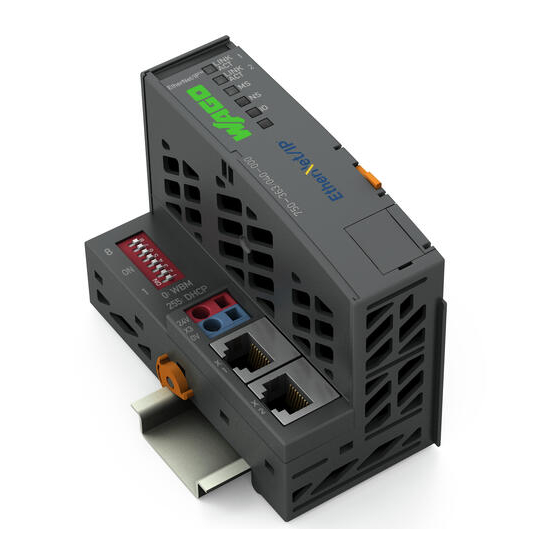
WAGO-I/O-SYSTEM 750 Device Description 750-363/0040-0000 FC EtherNet/IP G4 ECO XTR View The view below shows the different parts of the device: • The fieldbus connection is within the lower range on the left side. • Over the fieldbus connection is a power supply unit for the system supply. -
Page 52: Table 14: Legend For Figure "View
Device Description WAGO-I/O-SYSTEM 750 750-363/0040-0000 FC EtherNet/IP G4 ECO XTR Table 14: Legend for Figure “View” Desig- Pos. Meaning Details see Section nation LINK ACT „Device Description“ > 1, 2, MS, Status LEDs Fieldbus „Display Elements“ NS, I/O Marking possibility on four miniature WSB markers "Connect Devices"... -
Page 53: Connectors
WAGO-I/O-SYSTEM 750 Device Description 750-363/0040-0000 FC EtherNet/IP G4 ECO XTR Connectors 4.2.1 Data Contacts/Local Bus Communication between the fieldbus coupler/controller and the I/O modules as well as the system supply of the I/O modules is carried out via the local bus. The contacting for the local bus consists of 6 data contacts, which are available as self-cleaning gold spring contacts. -
Page 54: Power Jumper Contacts/Field Supply
750-363/0040-0000 FC EtherNet/IP G4 ECO XTR 4.2.2 Power Jumper Contacts/Field Supply The controller 750-363/0040-0000 is equipped with 2 self-cleaning power contacts for transferring of the field-side power supply to down-circuit I/O modules. These contacts are designed as spring contacts. Figure 26: Power Jumper Contacts Table 15: Legend for Figure “Power Jumper Contacts”... -
Page 55: Cage Clamp ® Connectors
WAGO-I/O-SYSTEM 750 Device Description 750-363/0040-0000 FC EtherNet/IP G4 ECO XTR 4.2.3 CAGE CLAMP Connectors ® Figure 27: CAGE CLAMP ® Connectors Table 16: Legend for Figure “CAGE CLAMP ® Connectors” Contact Designation Description 24 V System power supply voltage +24 V Field-side power supply voltage U −... -
Page 56: Device Supply
Device Description WAGO-I/O-SYSTEM 750 750-363/0040-0000 FC EtherNet/IP G4 ECO XTR 4.2.4 Device Supply The device is powered via terminal blocks with CAGE CLAMP ® connections. The device supply generates the necessary voltage to power the electronics of the device and the internal electronics of the connected I/O modules. -
Page 57: Fieldbus Connection
WAGO-I/O-SYSTEM 750 Device Description 750-363/0040-0000 FC EtherNet/IP G4 ECO XTR 4.2.5 Fieldbus Connection The connection to the fieldbus is made via two RJ-45 plugs, which are connected to the fieldbus controller via an integrated switch. The integrated switch works in store-and-forward operation and for each port, supports the transmission speeds 10/100 Mbit as well as the transmission modes full and half-duplex and autonegotiation. -
Page 58: Display Elements
Device Description WAGO-I/O-SYSTEM 750 750-363/0040-0000 FC EtherNet/IP G4 ECO XTR Display Elements The operating condition of the fieldbus coupler or the node is displayed with the help of illuminated indicators in the form of light-emitting diodes (LEDs). The LED information is routed to the top of the case by light guides. In some cases, the LEDs are multi-colored (red, green or orange). -
Page 59: Operating Elements
4.4.1 Service Interface The service interface is located behind the flap. It is used for the communication with the WAGO I/O-CHECK and WAGO Ethernet Settings. Figure 31: Service Interface (Closed and Opened Flap) Table 20: Legend for Figure “Service Interface (Closed and Opened Flap)”... -
Page 60: Address Selection Switch
Device Description WAGO-I/O-SYSTEM 750 750-363/0040-0000 FC EtherNet/IP G4 ECO XTR 4.4.2 Address Selection Switch Figure 32: Address Selection Switch (for example setting “0“) The 8-pole DIP switch is used to select the protocol for setting the IP address and as an address selection switch, to set the IP address. -
Page 61: Technical Data
WAGO-I/O-SYSTEM 750 Device Description 750-363/0040-0000 FC EtherNet/IP G4 ECO XTR Technical Data 4.5.1 Device Data Table 22: Technical Data – Device Width 112 mm Height (from upper edge of DIN-rail) 71.9 mm Depth 100 mm Weight 205.1 g Degree of protection IP20 4.5.2... -
Page 62: Supply
Device Description WAGO-I/O-SYSTEM 750 750-363/0040-0000 FC EtherNet/IP G4 ECO XTR 4.5.3 Supply Table 24: Technical Data – Supply Internal current consumption (5 VDC) 350 mA Total current for I/O modules (5 VDC) 1700 mA Input current at nominal load typ. -
Page 63: Fieldbus Ethernet/Ip
WAGO-I/O-SYSTEM 750 Device Description 750-363/0040-0000 FC EtherNet/IP G4 ECO XTR 4.5.4 Fieldbus EtherNet/IP Table 5: Technical Data - Fieldbus EtherNet/IP Input Process Image 1020 words Output Process Image 1020 words Number of „Encapsulation Sessions" Number of „Explicite Messaging“- Connections (Class 3) Number of „I/O Messaging“-... -
Page 64: Climatic Environmental Conditions
Device Description WAGO-I/O-SYSTEM 750 750-363/0040-0000 FC EtherNet/IP G4 ECO XTR 4.5.8 Climatic Environmental Conditions Table 30: Technical Data ‒ Climatic Environmental Conditions Surrounding air temperature, operation −40 °C … +70 °C Surrounding air temperature, storage −40 °C … +85 °C... -
Page 65: Mechanical Strength
WAGO-I/O-SYSTEM 750 Device Description 750-363/0040-0000 FC EtherNet/IP G4 ECO XTR 4.5.9 Mechanical Strength Table 31: Technical Data – Mechanical Strength Vibration resistance Acc. to IEC 60068-2-6 Comment to the vibration resistance: a) Type of oscillation: sweep with a rate of change of 1 octave per minute 10 Hz ≤... -
Page 66: Approvals
Approvals More information about approvals. Detailed references to the approvals are listed in the document “Overview Approvals WAGO I/O SYSTEM 750”, which you can find via the internet under: www.wago.com DOWNLOADS Documentation System Description. The following approvals have been granted to 750-363/0040-0000 fieldbus... -
Page 67: Standards And Guidelines
WAGO-I/O-SYSTEM 750 Device Description 750-363/0040-0000 FC EtherNet/IP G4 ECO XTR Standards and Guidelines 750-363/0040-0000 fieldbus coupler meets the following standards and guidelines: Table 33: Standards and Rated Conditions for Explosion Protection Applications ATEX acc. Directive 2014/34/EU General Requirements EN 60079-0... -
Page 68: Table 34: Climatic And Mechanical Environmental Conditions And Shipbuilding
Device Description WAGO-I/O-SYSTEM 750 750-363/0040-0000 FC EtherNet/IP G4 ECO XTR Table 34: Climatic and Mechanical Environmental Conditions and Shipbuilding Standard Test Value Transport EN 60870-2-2 Ct2(2k4) (except precipitation/water/moisture) Mechanical Environmental Conditions EN 61850-3 Achieved EN 60870-2-2 EN 60721-3-1 EN 60721-3-3... -
Page 69: Table 35: Emc - Immunity To Interference
WAGO-I/O-SYSTEM 750 Device Description 750-363/0040-0000 FC EtherNet/IP G4 ECO XTR The fieldbus coupler 750-363/0040-0000 meets the following EMC standards as these standards relate to the fieldbus coupler: Table 35: EMC – Immunity to Interference Standard Test Value Electrostatic Discharge • EN 61000-4-2 8 kV (contact discharge) •... - Page 70 Device Description WAGO-I/O-SYSTEM 750 750-363/0040-0000 FC EtherNet/IP G4 ECO XTR Table 35: EMC – Immunity to Interference Standard Test Value Line Frequency Disturbances • EN 60255-26 Standard not applicable Alternating Components of the Voltage to DC Line Connections • EN 61000-4-17 15 % •...
-
Page 71: Table 36: Emc - Emission Of Interference
WAGO-I/O-SYSTEM 750 Device Description 750-363/0040-0000 FC EtherNet/IP G4 ECO XTR Table 36: EMC – Emission of Interference Standard Test Value Enclosure Emission of Interference • EN 61000-6-3 30 dB(µV/m), QP, 30 MHz … 230 MHz • EN 55032 Class B 37 dB(µV/m), QP, 230 MHz …... -
Page 72: Table 37: Standards And Rated Conditions For Rail Applications (En 50155)
EN 50121-3-2 5.5 EMC (Emission of Interference, EN 50121-3-2 Immunity to Interference) EN 50121-4 EN 50121-5 9.11 Materials (Fire Protection) EN 45545-2 Hazard level HL3 WAGO is a company certified in accordance with the IRIS quality standard. Manual Version 1.0.0... -
Page 73: Mounting
WAGO-I/O-SYSTEM 750 Mounting 750-363/0040-0000 FC EtherNet/IP G4 ECO XTR Mounting Installation Position The following mounting positions are approved for the WAGO I/O SYSTEM 750 XTR: • Nominal mounting position (horizontal left) • Floor mounting position • Vertical top mounting position •... -
Page 74: Figure 33: Mounting Positions
Mounting WAGO-I/O-SYSTEM 750 750-363/0040-0000 FC EtherNet/IP G4 ECO XTR Figure 33: Mounting Positions Use an end stop in the case of vertical installation! When mounting in the “vertical top” or “vertical bottom" mounting position, also mount an end stop below the fieldbus node to protect the fieldbus node against sliding. -
Page 75: Overall Configuration
WAGO-I/O-SYSTEM 750 Mounting 750-363/0040-0000 FC EtherNet/IP G4 ECO XTR For vibration loads > 4g, observe the following installation instructions: • Use pan-head screws or blind rivets at least every 60 mm (12 mm pin spacing) to secure the DIN rail. -
Page 76: Mounting Onto Carrier Rail
WAGO Kontakttechnik GmbH & Co. KG supplies standardized carrier rails that are optimal for use with the I/O system. If other carrier rails are used, then a technical inspection and approval of the rail by WAGO Kontakttechnik GmbH & Co. KG should take place. -
Page 77: Wago Din Rails
WAGO-I/O-SYSTEM 750 Mounting 750-363/0040-0000 FC EtherNet/IP G4 ECO XTR 5.3.2 WAGO DIN Rails WAGO carrier rails meet the electrical and mechanical requirements shown in the table below. Table 38: WAGO DIN Rails Item No. Description 210-112 35 × 7.5; 1 mm; steel; bluish, tinned, chromed; slotted 210-113 35 ×... -
Page 78: Mounting Sequence
WAGO-I/O-SYSTEM 750 750-363/0040-0000 FC EtherNet/IP G4 ECO XTR Mounting Sequence Fieldbus couplers, controllers and I/O modules of the WAGO I/O SYSTEM 750 are snapped directly on a carrier rail in accordance with the European standard EN 60175 (DIN 35). The reliable positioning and connection is made using a tongue and groove system. -
Page 79: Inserting And Removing Devices
WAGO-I/O-SYSTEM 750 Mounting 750-363/0040-0000 FC EtherNet/IP G4 ECO XTR Mixed operation Mixed operation (standard/XTR modules) within a node is possible when groups of modules are electrically isolated on the field side (i.e., electrically isolated power supply). Inserting and Removing Devices Do not work when devices are energized! High voltage can cause electric shock or burns. -
Page 80: Removing The Fieldbus Coupler/Controller
Mounting WAGO-I/O-SYSTEM 750 750-363/0040-0000 FC EtherNet/IP G4 ECO XTR 5.6.2 Removing the Fieldbus Coupler/Controller Use a screwdriver blade to turn the locking disc until the nose of the locking disc no longer engages behind the carrier rail. Remove the fieldbus coupler/controller from the assembly by pulling the release tab. -
Page 81: Removing The I/O Module
WAGO-I/O-SYSTEM 750 Mounting 750-363/0040-0000 FC EtherNet/IP G4 ECO XTR Figure 37: Snap the I/O Module into Place (Example) With the I/O module snapped in place, the electrical connections for the data contacts and power jumper contacts (if any) to the fieldbus coupler/controller or to the previous or possibly subsequent I/O module are established. -
Page 82: Connect Devices
Connect Devices WAGO-I/O-SYSTEM 750 750-363/0040-0000 FC EtherNet/IP G4 ECO XTR Connect Devices Data Contacts/Local Bus Communication between the fieldbus coupler/controller and the I/O modules as well as the system supply of the I/O modules is carried out via the local bus. The contacting for the local bus consists of 6 data contacts, which are available as self-cleaning gold spring contacts. -
Page 83: Power Contacts/Field Supply
WAGO-I/O-SYSTEM 750 Connect Devices 750-363/0040-0000 FC EtherNet/IP G4 ECO XTR Power Contacts/Field Supply Risk of injury due to sharp-edged blade contacts! The blade contacts are sharp-edged. Handle the I/O module carefully to prevent injury. Do not touch the blade contacts. -
Page 84: Connecting A Conductor To The Cage Clamp
Do not connect more than one conductor at one single connection! If more than one conductor must be routed to one connection, these must be connected in an up-circuit wiring assembly, for example using WAGO feed- through terminals. For opening the CAGE CLAMP ®... -
Page 85: Function Description
WAGO-I/O-SYSTEM 750 Function Description 750-363/0040-0000 FC EtherNet/IP G4 ECO XTR Function Description Operating System After master configuration and electrical installation of the fieldbus station, the system is operative. The coupler begins running up after switching on the power supply or after a reset. -
Page 86: Process Data Architecture
Function Description WAGO-I/O-SYSTEM 750 750-363/0040-0000 FC EtherNet/IP G4 ECO XTR Process Data Architecture 7.2.1 Basic Structure After switching on the supply voltage, the fieldbus coupler identifies all I/O modules connected with the node that send or receive data (data width/bit width >... -
Page 87: Process Data Ethernet/Ip
WAGO-I/O-SYSTEM 750 Function Description 750-363/0040-0000 FC EtherNet/IP G4 ECO XTR 7.2.2 Process Data EtherNet/IP For some I/O modules (and their variations), the structure of the process data depends on the fieldbus. With EtherNet/IP, the process image is built up word-by-word (with word alignment). -
Page 88: Data Exchange
With the fieldbus coupler/controller, data is exchanged via the EtherNet/IP. In the EtherNet/IP network the master controller can be a PC or a PLC. The head stations of the WAGO I/O-SYSTEM 750 are slaves. The master requests communication. This request can be directed to certain head station by addressing. -
Page 89: Addressing
WAGO-I/O-SYSTEM 750 Function Description 750-363/0040-0000 FC EtherNet/IP G4 ECO XTR The input module data can be read by the CPU and by the fieldbus side. Likewise, data can be written to the output modules from the CPU and the fieldbus side. -
Page 90: Data Exchange Between Ethernet/Ip Master And I/O Modules
Function Description WAGO-I/O-SYSTEM 750 750-363/0040-0000 FC EtherNet/IP G4 ECO XTR Table 39: Data Width for I/O Modules Data width > 1 byte (channel) Data width = 1 bit (channel) Analog input modules Digital input modules Analog output modules Digital output modules... - Page 91 WAGO-I/O-SYSTEM 750 Function Description 750-363/0040-0000 FC EtherNet/IP G4 ECO XTR Additional Information: The assembly instances for the static assembly are described in the section “EtherNet/IP”. Manual Version 1.0.0...
-
Page 92: Commissioning
Commissioning WAGO-I/O-SYSTEM 750 750-363/0040-0000 FC EtherNet/IP G4 ECO XTR Commissioning This section shows a step-by-step procedure for starting up exemplarily a WAGO fieldbus node. Good example! This description is just an example and only serves to describe the procedure for a local start-up of a single fieldbus node with a PC under Windows. -
Page 93: Connecting Client Pc And Fieldbus Nodes
WAGO-I/O-SYSTEM 750 Commissioning 750-363/0040-0000 FC EtherNet/IP G4 ECO XTR Connecting Client PC and Fieldbus Nodes 1. Mount the fieldbus node on the TS 35 carrier rail. Follow the mounting instructions found in the “Mounting” chapter. 2. Connect the 24 V power supply to the supply terminals. -
Page 94: Assigning The Ip Address To The Fieldbus Node
IP address via the address selector switch. The basic IP address can be changed via the Web-based management or WAGO Ethernet settings (in the delivery state: 192.168.1.0). The subnet mask and default gateway values are taken from the static settings (as delivered: subnet mask = 255.255.255.0, default gateway = 0.0.0.0). -
Page 95: Figure 44: Address Selection Switch, For Example The Value Setting "50
WAGO-I/O-SYSTEM 750 Commissioning 750-363/0040-0000 FC EtherNet/IP G4 ECO XTR Table 40: Address selection switch values (host ID) Address selection switch Description Address selection switch is enabled. The host ID is set to a fixed value between 1 ... 254. The IP address consists of the static base address 1 …... -
Page 96: Assigning Ip Address Via Dhcp
DHCP server to be permanently available. If there is no DHCP server available after a Power On reset, the network will remain inactive. If DHCP is not active, it is necessary to enable DHCP, e. g. via "WAGO Ethernet Settings" or via the WBM (see chapters "Enable DHCP via "WAGO Ethernet Settings"... - Page 97 WAGO-I/O-SYSTEM 750 Commissioning 750-363/0040-0000 FC EtherNet/IP G4 ECO XTR Via DHCP assigned IP addresses are only temporarily valid! Note that an IP address assigned via DHCP is limited in time. If the DHCP server is not available at the end of its useful life, the fieldbus node sets the IP address free and then the fieldbus node is no longer accessible! In order to use the IP address permanently, change it to “static”...
-
Page 98: Enable Dhcp Via "Wago Ethernet Settings" (Without Existing Ip Address)
"Dynamic Host Configuration Protocol" (DHCP). However, if DHCP is not active and you do not have access to your fieldbus node via an IP address, you can enable DHCP via "WAGO Ethernet Settings" in the Network tab. -
Page 99: Enable Dhcp Via Wbm (With Existing Ip Address)
WAGO-I/O-SYSTEM 750 Commissioning 750-363/0040-0000 FC EtherNet/IP G4 ECO XTR 8.3.2.2 Enable DHCP via WBM (with existing IP address) In the delivery state of the head station, the dynamic assignment of the IP address is active by means of "Dynamic Host Configuration Protocol" (DHCP). -
Page 100: Assigning Ip Address Via "Wago Ethernet Settings
Flash File System in which the WBM pages of the fieldbus coupler/controller are stored. "WAGO Ethernet Settings" can be used via the serial service interface or via the ETHERNET interface. - Page 101 Click on the [Write] button to apply the settings in the fieldbus node. You can now close "WAGO Ethernet Settings" or make other changes in the Web-based Management System as required. To open the Web-based Management System click on the button [Start WBM] on the right side.
-
Page 102: Assigning The Ip Address Via Bootp
By default, DHCP is active in the delivery state of the head station. Therefor it is necessary to enable BootP for IP address assignment via BootP, e. g. via "WAGO Ethernet Settings" or via the WBM (see analog the chapters "Activate DHCP via "WAGO Ethernet Settings" (without existing IP address)" or "Activate DHCP via WBM (with existing IP address)"). - Page 103 IP address for your fieldbus node. Enable the query/response mechanism of the BootP protocol based on the handling, which depends on the BootP program set or e. g. in “WAGO Ethernet Settings“ (Network tab, Source “BootP”). To apply the new IP address, use e.g. a hardware reset to restart your fieldbus node by interrupt the voltage supply for approx.
-
Page 104: Reasons For Failed Ip Address Assignment
104 Commissioning WAGO-I/O-SYSTEM 750 750-363/0040-0000 FC EtherNet/IP G4 ECO XTR 8.3.4.1 Reasons for Failed IP Address Assignment • The PC on whom the BootP server is running is not located in the network as the fieldbus coupler/controller; i.e., the IP addresses do not match. -
Page 105: Apply Ip Address Permanently (Option "Static")
WAGO-I/O-SYSTEM 750 Commissioning 105 750-363/0040-0000 FC EtherNet/IP G4 ECO XTR Apply IP address permanently (option “static“) For permanent address assignment, the IP stored in the EEPROM must be used! To apply permanently the new IP address assigned via DHCP or BootP in the fieldbus coupler/controller, the assigned or desired settings for IP address, subnet mask and default gateway must be entered on the WBM “TCP/IP”... -
Page 106: Testing The Function Of The Fieldbus Node
106 Commissioning WAGO-I/O-SYSTEM 750 750-363/0040-0000 FC EtherNet/IP G4 ECO XTR Testing the Function of the Fieldbus Node To ensure that the IP address is correct and to test communication with the fieldbus node, first turn off the operating voltage of the fieldbus node. -
Page 107: Preparing The Flash File System
WAGO-I/O-SYSTEM 750 Commissioning 107 750-363/0040-0000 FC EtherNet/IP G4 ECO XTR Preparing the Flash File System The flash file system must be prepared in order to use the WBM of the fieldbus coupler/controller of the fieldbus node to make all configurations. - Page 108 108 Commissioning WAGO-I/O-SYSTEM 750 750-363/0040-0000 FC EtherNet/IP G4 ECO XTR In the top menu bar, select [Reset File System] to format the file system and to extract the WBM pages of the flash file system. Formatting and extracting is complete when the status window displays "Resetting the file system successfully".
-
Page 109: Synchronizing The System Time
System time will be reset when the fieldbus node is de-energized! The head station 750-363/0040-0000 does not have a real-time clock. For this reason, the current system time will be reset when the fieldbus node is de-... - Page 110 Select “Clock” in the left navigation bar. Enter your user name and password in the displayed query dialog box (default: user = "admin", password = "wago" or: user = "user", password = "user"). The WBM page "Clock" is displayed. Set the current time and date values, as well as the time zone deviation in the input fields, and select the desired option for the display and Daylight Saving Time (DST).
-
Page 111: Restoring Factory Settings
WAGO-I/O-SYSTEM 750 Commissioning 111 750-363/0040-0000 FC EtherNet/IP G4 ECO XTR Restoring Factory Settings To restore the factory settings, proceed as follows: Switch off the supply voltage of the fieldbus node. Connect the communication cable 750-920 or 750-923 respectively the ®... -
Page 112: Configuring Via The Web-Based Management System (Wbm)
112 Configuring via the Web-Based Management System (WBM) WAGO-I/O-SYSTEM 750 750-363/0040-0000 FC EtherNet/IP G4 ECO XTR Configuring via the Web-Based Management System (WBM) An integrated Web server can be used for configuration and administration of the device. The HTML pages together, they are referred to as the Web-based Management System (WBM). -
Page 113: Open Wbm
The first time a configuration page is called, a login dialog appears Enter your user name and password in the query dialog (default: user = “admin”, password = “wago” or user = “user”, password = “user”). The corresponding WBM page is loaded. -
Page 114: Wbm
114 Configuring via the Web-Based Management System (WBM) WAGO-I/O-SYSTEM 750 750-363/0040-0000 FC EtherNet/IP G4 ECO XTR WBM Pages You can access the available WBM pages via the links given in the navigation bar on the left side. The configuration pages, listed below, are following described. -
Page 115: Information
WAGO-I/O-SYSTEM 750 Configuring via the Web-Based Management System (WBM) 115 750-363/0040-0000 FC EtherNet/IP G4 ECO XTR Information The WBM page “Information” contains an overview of all important information about your fieldbus coupler. Table 42: WBM Page “Information” Device details Entry... -
Page 116: Administration
116 Configuring via the Web-Based Management System (WBM) WAGO-I/O-SYSTEM 750 750-363/0040-0000 FC EtherNet/IP G4 ECO XTR Administration Use the “Administration” WBM page to set configuration options for basic administration purposes, such as boot behavior, authentication, and SSL certificate. These configuration options are stored in non-volatile memory when the [SUBMIT] button is pressed. - Page 117 WAGO-I/O-SYSTEM 750 Configuring via the Web-Based Management System (WBM) 117 750-363/0040-0000 FC EtherNet/IP G4 ECO XTR The following default groups exist: User: admin Password: wago User: user Password: user User: guest Password: guest SSL Certificates Entry Button Status Description (Example)
-
Page 118: Clock
00:00:00 a.m. and has to synchronize with the computer’s current time. Use a WAGO RTC module for time synchronization!! You can use a WAGO 750-640 RTC Module for your node to utilize the actual encoded time (Real-time – RTC) in your higher-level control system. -
Page 119: Miscellaneous
WAGO-I/O-SYSTEM 750 Configuring via the Web-Based Management System (WBM) 119 750-363/0040-0000 FC EtherNet/IP G4 ECO XTR Table 44: WBM Page „Clock“ Clock Settings Entry Default Value (example) Description Device local time Set current time 00:00:00 08:30:38 (HH:MM:SS) Device local date... -
Page 120: Storage Media
120 Configuring via the Web-Based Management System (WBM) WAGO-I/O-SYSTEM 750 750-363/0040-0000 FC EtherNet/IP G4 ECO XTR These configuration options are stored in non-volatile memory when the [SUBMIT] button is pressed. Changes to the configuration options take effect after the next power-on cycle or software reset. -
Page 121: Update
WAGO-I/O-SYSTEM 750 Configuring via the Web-Based Management System (WBM) 121 750-363/0040-0000 FC EtherNet/IP G4 ECO XTR Table 46: WBM page "Storage Media" Local Disks Entry Value (Example) Description Drive Letter Directory Total Size [kB] 1050184 kB Total size of the file system... -
Page 122: Ethernet
122 Configuring via the Web-Based Management System (WBM) WAGO-I/O-SYSTEM 750 750-363/0040-0000 FC EtherNet/IP G4 ECO XTR 9.10 Ethernet Use the “Ethernet” WBM page to set the data transfer rate, the MAC address filter settings and bandwidth limit for each of the two switch ports for data transfer via Ethernet. - Page 123 WAGO-I/O-SYSTEM 750 Configuring via the Web-Based Management System (WBM) 123 750-363/0040-0000 FC EtherNet/IP G4 ECO XTR MAC Address Filter Settings Entry Default value Description Enable filter Activate MAC address filter. Depending on the operating mode of the MAC address filter (whitelist / blacklist), the subsequently ...
- Page 124 124 Configuring via the Web-Based Management System (WBM) WAGO-I/O-SYSTEM 750 750-363/0040-0000 FC EtherNet/IP G4 ECO XTR Switch Settings Entry Default value Description Enable “Fast Aging” "Fast Aging" ensures that the cache for the MAC addresses is cleared faster in the switch. This may be required if a redundancy system (e.g., using a Jet-...
- Page 125 WAGO-I/O-SYSTEM 750 Configuring via the Web-Based Management System (WBM) 125 750-363/0040-0000 FC EtherNet/IP G4 ECO XTR All ETHERNET ports cannot be disabled! Both ETHERNET ports can be switched off. If both ports are disabled and you press [SUBMIT], the selection is not applied and the previous values are restored.
-
Page 126: Protocols
To reduce the risk of cyber attacks and, thus, enhance your cyber security, close all ports and services in the control components (e.g., Port 6626 for WAGO I/O-CHECK, Port 2455 for CODESYS 2 and Port 11740 for e!COCKPIT) not required by your application. -
Page 127: Snmp
WAGO-I/O-SYSTEM 750 Configuring via the Web-Based Management System (WBM) 127 750-363/0040-0000 FC EtherNet/IP G4 ECO XTR 9.12 SNMP On the HTML pages „SNMP“, you can perform the settings for the Simple Network Management Protocol (SNMP v1/v2c and v3). SNMP is a standard for device management within a TCP/IP network. The... -
Page 128: Snmp V1/V2C
128 Configuring via the Web-Based Management System (WBM) WAGO-I/O-SYSTEM 750 750-363/0040-0000 FC EtherNet/IP G4 ECO XTR 9.12.1 SNMP v1/v2c The SNMP version 1/2c represents a community message exchange. The community name of the network community must thereby be specified. Table 50: WBM Page “SNMP v1/v2”... -
Page 129: Snmp V3
WAGO-I/O-SYSTEM 750 Configuring via the Web-Based Management System (WBM) 129 750-363/0040-0000 FC EtherNet/IP G4 ECO XTR 9.12.2 SNMP V3 In SNMP version 3, exchanging messages is user-related. Each device, that knows the passwords set via WBM, may read or write values from the fieldbus coupler. -
Page 130: Sntp
130 Configuring via the Web-Based Management System (WBM) WAGO-I/O-SYSTEM 750 750-363/0040-0000 FC EtherNet/IP G4 ECO XTR 9.13 SNTP On the WBM page “SNTP”, you can perform the settings for the “Simple Network Time Protocol”. The SNTP client supports configuration of static time servers. Two additional servers may be assigned by dynamic network configuration (e. - Page 131 WAGO-I/O-SYSTEM 750 Configuring via the Web-Based Management System (WBM) 131 750-363/0040-0000 FC EtherNet/IP G4 ECO XTR Tabelle 53: WBM-Seite „TCP/IP“ Network Settings (non-volatile) Eintrag Standardwert Wert (Beispiel) Beschreibung Activate “Bootstrap Protocol“. BootP Deactivate “Bootstrap Protocol“. Activate “Dynamic Host ...
-
Page 132: Ethernet/Ip
132 Configuring via the Web-Based Management System (WBM) WAGO-I/O-SYSTEM 750 750-363/0040-0000 FC EtherNet/IP G4 ECO XTR 9.15 EtherNet/IP Use the EtherNet/IP WBM page to configure settings for the EtherNet/IP adapter functionality and download the Electronic Device Description (EDS) file. In addition, information is displayed about the provided static assemblies and the mapping of the inserted I/O modules for the EtherNet/IP process image. - Page 133 WAGO-I/O-SYSTEM 750 Configuring via the Web-Based Management System (WBM) 133 750-363/0040-0000 FC EtherNet/IP G4 ECO XTR Assembly-Information Entry Example Description Number of the assembly instance Instance provided by the device. Description of the content of the Description „AI data, DI data, status and …“...
-
Page 134: I/O Config
134 Configuring via the Web-Based Management System (WBM) WAGO-I/O-SYSTEM 750 750-363/0040-0000 FC EtherNet/IP G4 ECO XTR 9.16 I/O Config Click the link “I/O config” to view the number of modules that are connected to your hardware. The data in the second line are not relevant for the present fieldbus coupler, because no I/O configuration will be load onto devices which have no runtime system (PLC). -
Page 135: Diagnostics
WAGO-I/O-SYSTEM 750 Diagnostics 135 750-363/0040-0000 FC EtherNet/IP G4 ECO XTR Diagnostics 10.1 LED Signaling For on-site diagnostics, the fieldbus coupler has several LEDs that indicate the operational status of the fieldbus coupler or the entire node (see following figure). Figure 46: Display Elements The diagnostics displays and their significance are explained in detail in the following section. -
Page 136: Evaluating Fieldbus Status
136 Diagnostics WAGO-I/O-SYSTEM 750 750-363/0040-0000 FC EtherNet/IP G4 ECO XTR 10.1.1 Evaluating Fieldbus Status The health of the ETHERNET Fieldbus is signaled through the top LED group ('LINK ACT 1, 2', 'MS', und 'NS'). The two-colored LEDs ‘MS’ (module status) and ‘NS’ (network status) are solely used by the EtherNet/IP protocol. -
Page 137: Evaluating Node Status - I/O Led (Blink Code Table)
WAGO-I/O-SYSTEM 750 Diagnostics 137 750-363/0040-0000 FC EtherNet/IP G4 ECO XTR 10.1.2 Evaluating Node Status – I/O LED (Blink Code Table) The communication status between fieldbus coupler/controller and the I/O modules is indicated by the I/O LED. Table 58: Node Status Diagnostics – Solution in Event of Error... -
Page 138: Figure 47: Node Status - I/O Led Signaling
138 Diagnostics WAGO-I/O-SYSTEM 750 750-363/0040-0000 FC EtherNet/IP G4 ECO XTR Figure 47: Node Status – I/O LED Signaling Figure 48: Error Message Coding Example of a module error: • The I/O LED starts the error display with the first flashing sequence (approx. - Page 139 WAGO-I/O-SYSTEM 750 Diagnostics 139 750-363/0040-0000 FC EtherNet/IP G4 ECO XTR Error argument 12 means that the local bus is interrupted behind the twelfth I/O module. The thirteenth I/O module is either defective or has been pulled out of the assembly.
-
Page 140: Table 59: Blink Code- Table For The I/O Led Signaling, Error Code 1
140 Diagnostics WAGO-I/O-SYSTEM 750 750-363/0040-0000 FC EtherNet/IP G4 ECO XTR Table 59: Blink code- table for the I/O LED signaling, error code 1 Error code 1: "Hardware and configuration error" Error Error Description Solution Argument Overflow of the 1. Turn off the power supply of the node. -
Page 141: Table 60: Blink Code Table For The I/O Led Signaling, Error Code 2
WAGO-I/O-SYSTEM 750 Diagnostics 141 750-363/0040-0000 FC EtherNet/IP G4 ECO XTR Table 59: Blink code- table for the I/O LED signaling, error code 1 Error code 1: "Hardware and configuration error" Error Error Description Solution Argument 1. Turn off the power supply of the node. -
Page 142: Table 61: Blink Code Table For The I/O Led Signaling, Error Code 3
142 Diagnostics WAGO-I/O-SYSTEM 750 750-363/0040-0000 FC EtherNet/IP G4 ECO XTR Table 61: Blink Code Table for the I/O LED Signaling, Error Code 3 Error Code 3: „Protocoll error, local bus“ Error Error Description Solution Argument -- Are there power supply modules with the bus power supply (750-613) in the node? --- 1. -
Page 143: Table 62: Blink Code Table For The I/O Led Signaling, Error Code 4
WAGO-I/O-SYSTEM 750 Diagnostics 143 750-363/0040-0000 FC EtherNet/IP G4 ECO XTR Table 62: Blink Code Table for the I/O LED Signaling, Error Code 4 Error Code 4: „Physical error, local bus“ Error Error Description Solution Argument 1. Turn off the power supply of the node. -
Page 144: Table 64: Blink Code Table For The I/O Led Signaling, Error Code 6
144 Diagnostics WAGO-I/O-SYSTEM 750 750-363/0040-0000 FC EtherNet/IP G4 ECO XTR Table 64: Blink Code Table for the I/O LED Signaling, Error Code 6 Error Code 6: " Configuration error, node configuration" Error Error Description Solution Argument 1. Turn off the power supply of the node. -
Page 145: Table 67: Blink Code Table For I/O Led Signaling, Error Code 12
3. If the error still exists, please contact the I/O Support. 1. Reset the file system using “WAGO Ethernet Settings“, button [Reset File System] in the menu above. General error of the file 2. Restart the fieldbus node by turning the power supply system off and on again. -
Page 146: Fault Behavior
146 Diagnostics WAGO-I/O-SYSTEM 750 750-363/0040-0000 FC EtherNet/IP G4 ECO XTR 10.2 Fault Behavior 10.2.1 Fieldbus Failure For the fieldbus connections, the EtherNet/IP master (scanner) and the slave (adapter) use integrated timeout monitoring. If there is a fieldbus failure, the established connections are no longer serviced and the connection partners detect a timeout condition. - Page 147 WAGO-I/O-SYSTEM 750 Diagnostics 147 750-363/0040-0000 FC EtherNet/IP G4 ECO XTR If the local bus error is caused by a defective module, it must be replaced, as described in the blink code table for error code 4 under "Solution". Manual Version 1.0.0...
-
Page 148: Fieldbus Communication
WAGO fieldbus coupler/controller based on ETHERNET. These protocols are explained in more detail in the other sections. -
Page 149: Table 70: Network Class A
WAGO-I/O-SYSTEM 750 Fieldbus Communication 149 750-363/0040-0000 FC EtherNet/IP G4 ECO XTR IP Addresses To allow communication over the network each fieldbus node requires a 32 bit Internet address (IP address). IP Address must be unique! For error free operation, the IP address must be unique within the network. -
Page 150: Table 73: Key Data Class A, B And C
192.000.000.XXX ... Approx. 2 Million 223.255.255.XXX Each WAGO ETHERNET fieldbus coupler or controller can be easily assigned an IP address via the implemented BootP protocol. For small internal networks we recommend selecting a network address from Class C. Do not set IP addresses to 0.0.0.0 or 255.255.255.255! Never set all bits to equal 0 or 1 in one byte (byte = 0 or 255). -
Page 151: Table 74: Example: Class B Address With Field For Subnet Ids
WAGO-I/O-SYSTEM 750 Fieldbus Communication 151 750-363/0040-0000 FC EtherNet/IP G4 ECO XTR Table 74: Example: Class B Address with Field for Subnet IDs Network ID Subnet ID Host ID Subnet Mask A subnet mask was introduced to encode the subnets in the Internet. This involves a bit mask, which is used to mask out or select specific bits of the IP address. - Page 152 152 Fieldbus Communication WAGO-I/O-SYSTEM 750 750-363/0040-0000 FC EtherNet/IP G4 ECO XTR Specification of the network mask necessary! Specify the network mask defined by the administrator in the same way as the IP address when installing the network protocol. Gateway The subnets of the Internet are normally connected via gateways. The function of these gateways is to forward packets to other networks or subnets.
-
Page 153: Tcp (Transmission Control Protocol)
WAGO-I/O-SYSTEM 750 Fieldbus Communication 153 750-363/0040-0000 FC EtherNet/IP G4 ECO XTR physically receives every packet. The resolution of IP address to Ethernet address is solved by the use of algorithms, IP multicast addresses are embedded in Ethernet multicast addresses. 11.1.1.2... -
Page 154: Configuration And Diagnostics Protocols
154 Fieldbus Communication WAGO-I/O-SYSTEM 750 750-363/0040-0000 FC EtherNet/IP G4 ECO XTR 11.1.2 Configuration and Diagnostics Protocols 11.1.2.1 BootP (Bootstrap Protocol) The “Bootstrap Protocol” (BootP) can be used to assign an IP address and other parameters to the head station of the fieldbus node in a TCP/IP network. -
Page 155: Dhcp (Dynamic Host Configuration Protocol)
WAGO-I/O-SYSTEM 750 Fieldbus Communication 155 750-363/0040-0000 FC EtherNet/IP G4 ECO XTR Table 79: BootP Options Option Meaning [OPT1] Subnet mask 32-bit address mask that displays which bits of the IP address identify the network and which identify the network stations. - Page 156 156 Fieldbus Communication WAGO-I/O-SYSTEM 750 750-363/0040-0000 FC EtherNet/IP G4 ECO XTR • Manual assignment In this mode, the IP addresses are permanently assigned on the DHCP server to specific MAC addresses. The addresses are assigned to the MAC address for an indefinite period.
-
Page 157: Http (Hypertext Transfer Protocol)
The HTTP server uses port number 80. 11.1.2.4 DNS (Domain Name Systems) The DNS client enables conversion of logical Internet names such as www.wago.com into the appropriate decimal IP address represented with separator stops, via a DNS server. Reverse conversion is also possible. Manual Version 1.0.0... -
Page 158: Sntp-Client (Simple Network Time Protocol)
158 Fieldbus Communication WAGO-I/O-SYSTEM 750 750-363/0040-0000 FC EtherNet/IP G4 ECO XTR The addresses of the DNS server are configured via DHCP, BootP or web-based management. Up to 2 DNS servers can be specified. The host identification can be achieved with two functions; an internal host table is not supported. -
Page 159: Snmp (Simple Network Management Protocol)
“MIB objects”. The SNMP of the ETHERNET controller includes both the general MIB acc. to RFC1213 (MIB II) and a special WAGO MIB. SNMP is processed via port 161. The port number for SNMP traps (agent messages) is 161. Both ports must be enabled to use SNMP. -
Page 160: 11.1.2.7.1 Mib Ii Description
160 Fieldbus Communication WAGO-I/O-SYSTEM 750 750-363/0040-0000 FC EtherNet/IP G4 ECO XTR 11.1.2.7.1 MIB II Description MIB II acc. to RFC1213 is divided into the following groups: Table 82: MIB II groups Group Identifier System Group 1.3.6.1.2.1.1 Interface Group 1.3.6.1.2.1.2 IP Group 1.3.6.1.2.1.4... -
Page 161: 11.1.2.7.2 Traps
WAGO-I/O-SYSTEM 750 Fieldbus Communication 161 750-363/0040-0000 FC EtherNet/IP G4 ECO XTR 11.1.2.7.2 Traps Standard Traps For specific events, the SNMP agent will independently send one of the following messages without polling the manager. Enable event messages (traps) in the WBM! Initially enable the event messages in the WBM in menu “SNMP”... -
Page 162: Application Protocols
162 Fieldbus Communication WAGO-I/O-SYSTEM 750 750-363/0040-0000 FC EtherNet/IP G4 ECO XTR 11.1.3 Application Protocols If fieldbus specific application protocols are implemented, then the appropriate fieldbus specific communication is possible with the respective coupler/controller. Thus the user is able to have a simple access from the respective fieldbus on the fieldbus node. -
Page 163: Ethernet/Ip (Ethernet/Industrial Protocol)
WAGO-I/O-SYSTEM 750 Fieldbus Communication 163 750-363/0040-0000 FC EtherNet/IP G4 ECO XTR 11.2 EtherNet/IP (Ethernet/Industrial Protocol) 11.2.1 General EtherNet/IP stands for Ethernet Industrial Protocol and defines an open industry standard that extends the classic Ethernet with an industrial protocol. This standard was jointly developed by ControlNet International (CI) and the Open DeviceNet Vendor Association (ODVA) with the help of the Industrial Ethernet Association (IEA). -
Page 164: Protocol Overview In The Osi Model
164 Fieldbus Communication WAGO-I/O-SYSTEM 750 750-363/0040-0000 FC EtherNet/IP G4 ECO XTR 11.2.2 Protocol overview in the OSI model In order to clarify the interrelationships between DeviceNet, ControlNet and EtherNet/IP, the following diagram presents the associated ISO/OSI reference model. Table 84: ISO/OSI reference model... -
Page 165: Characteristics Of The Ethernet/Ip Protocol Software
The EDS file required for EtherNet/IP operation is imported and installed by the corresponding configuration software. Downloading the EDS file! You can download the EDS file in the download area of the WAGO web site: http://www.wago.com. Information about installing the EDS file When installing the EDS file, refer to the information provided in the documentation of the configuration software, which you are using. -
Page 166: Object Model
166 Fieldbus Communication WAGO-I/O-SYSTEM 750 750-363/0040-0000 FC EtherNet/IP G4 ECO XTR 11.2.5 Object Model 11.2.5.1 General For network communication, EtherNet/IP utilizes an object model in which all functions and data of a device are described. Each node in the network is depicted as a collection of objects. -
Page 167: Class Overview
CIP”). WAGO-specific classes listed in the overview table below are also available. All CIP Common classes listed and the WAGO-specific classes listed below that are described in detail in the following individual sections after a brief explanation of the table headings in the object descriptions. -
Page 168: Table 86: Overview Wago Specific Classes
168 Fieldbus Communication WAGO-I/O-SYSTEM 750 750-363/0040-0000 FC EtherNet/IP G4 ECO XTR Table 86: Overview WAGO specific Classes Class Name Coupler/Controller Configuration Object Discrete Input Point Discrete Output Point Analog Input Point Analog Output Point Discrete Input Point Extended 1 Discrete Output Point Extended 1... -
Page 169: Explanation Of The Table Headings In The Object Descriptions
WAGO-I/O-SYSTEM 750 Fieldbus Communication 169 750-363/0040-0000 FC EtherNet/IP G4 ECO XTR 11.2.5.3 Explanation of the Table Headings in the Object Descriptions Table 87: Explanation of the table headings in the object descriptions Table heading Description Attribute ID Integer value which is assigned to the corresponded attribute... -
Page 170: Table 89: Identity
170 Fieldbus Communication WAGO-I/O-SYSTEM 750 750-363/0040-0000 FC EtherNet/IP G4 ECO XTR Instance 1 Table 89: Identity (01 ) – Instance 1 Attribute ID Acces Name Data type Description Default value Vendor ID UINT Manufacturer 40 (0x0028) identification Device Type UINT... -
Page 171: Message Router
WAGO-I/O-SYSTEM 750 Fieldbus Communication 171 750-363/0040-0000 FC EtherNet/IP G4 ECO XTR Common Services Table 90: Identity (01 ) – Common service Service code Service Service name Description available Class Instance Get_Attribute_All Supplies contents of all attributes Reset Implements the reset service... -
Page 172: Assembly Object
By means of the assembly classes, even several diverse objects can be combined. These could be, for example, input and output data, status and control information or diagnostic information. WAGO uses the manufacturer-specific instances in order to provide these objects for you in various arrangements. This gives you an efficient way to exchange process data. -
Page 173: Table 96: Static Assembly Instances - Instance
WAGO-I/O-SYSTEM 750 Fieldbus Communication 173 750-363/0040-0000 FC EtherNet/IP G4 ECO XTR Instance 101 (65 This assembly instance contains analog and digital output data. Table 96: Static assembly instances – Instance 101 (65 Attribute ID Access Name Data type Description Default value... -
Page 174: Table 100: Static Assembly Instances - Instance
174 Fieldbus Communication WAGO-I/O-SYSTEM 750 750-363/0040-0000 FC EtherNet/IP G4 ECO XTR Instance 105 (69 This assembly instance contains digital input data and the status only. Table 100: Static assembly instances – Instance 105 (69 Attribute ID Acces Name Data type... -
Page 175: Table 104: Static Assembly Instances - Instance
WAGO-I/O-SYSTEM 750 Fieldbus Communication 175 750-363/0040-0000 FC EtherNet/IP G4 ECO XTR Instance 109 (6D This assembly instance contains analog input data. Table 104: Static assembly instances – Instance 109 (6C Attribute ID Acces Name Data type Description Default value Data... -
Page 176: Connection Manager
176 Fieldbus Communication WAGO-I/O-SYSTEM 750 750-363/0040-0000 FC EtherNet/IP G4 ECO XTR 11.2.5.7 Connection Manager (06 The “Connection Manager Object” provides the internal resources that are required for the input and output data and explicit messages. In addition, the administration of this resource is an assignment of the “Connection Manager Object”. -
Page 177: Table 106: Tcp/Ip Interface
WAGO-I/O-SYSTEM 750 Fieldbus Communication 177 750-363/0040-0000 FC EtherNet/IP G4 ECO XTR Instance 0 (Class Attributes) Table 106: TCP/IP interface (F5 ) – Class Attribute ID Access Name Data type Description Default value Revision UINT Revision of this object 4 (0x0004) -
Page 178: Table 107: Tcp/Ip Interface
178 Fieldbus Communication WAGO-I/O-SYSTEM 750 750-363/0040-0000 FC EtherNet/IP G4 ECO XTR Instance 1 Table 107: TCP/IP interface (F5 ) – Instance 1 Attribute ID Acces NV Name Data type Description Default value Status DWORD Interface state Configuration DWORD Interface flags for possible... -
Page 179: Ethernet Link
WAGO-I/O-SYSTEM 750 Fieldbus Communication 179 750-363/0040-0000 FC EtherNet/IP G4 ECO XTR Common Services Table 108: TCP/IP interface (F5 ) – Common service Service code Service Service name Description available Class Instance Get_Attribute_All Supplies contents of all attributes Get_Attribute_Single Supplies contents of the appropriate attribute... -
Page 180: Table 110: Ethernet Link
180 Fieldbus Communication WAGO-I/O-SYSTEM 750 750-363/0040-0000 FC EtherNet/IP G4 ECO XTR Instance 1 Table 110: Ethernet link (F6 ) – Instance 1 Attribute ID Acces Name Data type Description Default value Interface Speed UDINT Transfer rate (0x00000064) Interface Flags DWORD... - Page 181 WAGO-I/O-SYSTEM 750 Fieldbus Communication 181 750-363/0040-0000 FC EtherNet/IP G4 ECO XTR Table 110: Ethernet link (F6 ) – Instance 1 Attribute ID Acces Name Data type Description Default value Get/ Admin State USINT Admin status: 1 (0x01) Value 0: Reserved...
-
Page 182: Table 111: Ethernet Link
182 Fieldbus Communication WAGO-I/O-SYSTEM 750 750-363/0040-0000 FC EtherNet/IP G4 ECO XTR Instance 2 – Port 2 Table 111: Ethernet link (F6 ) – Instance 2 Attribute ID Acces Name Data type Description Default value Interface Speed UDINT Transfer rate (0x00000064) - Page 183 WAGO-I/O-SYSTEM 750 Fieldbus Communication 183 750-363/0040-0000 FC EtherNet/IP G4 ECO XTR Table 111: Ethernet link (F6 ) – Instance 2 Attribute ID Acces Name Data type Description Default value Get/ Admin State USINT Admin status: 1 (0x01) Value 0: Reserved...
-
Page 184: Table 112: Ethernet Link
184 Fieldbus Communication WAGO-I/O-SYSTEM 750 750-363/0040-0000 FC EtherNet/IP G4 ECO XTR Instance 3 – Internal Port 3 Table 112: Ethernet link (F6 ) – Instance 3 Attribute ID Acces Name Data type Description Default value Interface Speed UDINT Transfer rate... -
Page 185: Coupler/Controller Configuration
WAGO-I/O-SYSTEM 750 Fieldbus Communication 185 750-363/0040-0000 FC EtherNet/IP G4 ECO XTR Common Services Table 113: Ethernet link (F6 ) – Common service Service code Service Service-Name Description available Class Instance Get_Attribute_All Supplies contents of all attributes Get_Attribute_Single Supplies contents of the appropriate attribute... -
Page 186: Table 115: Coupler/Controller Configuration
186 Fieldbus Communication WAGO-I/O-SYSTEM 750 750-363/0040-0000 FC EtherNet/IP G4 ECO XTR Instance 1 Table 115: Coupler/Controller configuration (64 ) – Instance 1 Attribute ID Acces NV Name Data type Description Default value ProcessStat USINT State of coupler/controller, error mask: Bit 0: Local bus error... -
Page 187: Discrete Input Point
WAGO-I/O-SYSTEM 750 Fieldbus Communication 187 750-363/0040-0000 FC EtherNet/IP G4 ECO XTR 120 (0x78) NV Bk_Header UINT Indicates whether the 0x0000 CfgOT RUN/IDLE header is used originator target direction 0: is used 1: is not used 121(0x79) NV Bk_Header UINT... -
Page 188: Discrete Input Point Extended 2 (6D )
188 Fieldbus Communication WAGO-I/O-SYSTEM 750 750-363/0040-0000 FC EtherNet/IP G4 ECO XTR 11.2.5.12 Discrete Input Point Extended 1 (69 The extension of the “Discrete Input Point” class enables the reading of data from a fieldbus node that contains over 255 digital input points (DIPs). The instance scope of the “Discrete Input Point Extended 1”... -
Page 189: Discrete Input Point Extended
WAGO-I/O-SYSTEM 750 Fieldbus Communication 189 750-363/0040-0000 FC EtherNet/IP G4 ECO XTR Instance 1 ... 255 (Digital input value 511 up to 765) Table 124: Analog input point (67 ) – Instance 1 Attribute ID Acces Name Data type Description Default value... -
Page 190: Discrete Output Point
190 Fieldbus Communication WAGO-I/O-SYSTEM 750 750-363/0040-0000 FC EtherNet/IP G4 ECO XTR 11.2.5.15 Discrete Output Point (66 This class enables data exchange for a particular digital output point. Instance 0 (Class Attributes) Table 129: Discrete Output Point (66 hex) – Class... -
Page 191: Discrete Output Point Extended 2 (6E )
WAGO-I/O-SYSTEM 750 Fieldbus Communication 191 750-363/0040-0000 FC EtherNet/IP G4 ECO XTR Instance 1 ... 255 (Digital output value 256 up to 510) Table 133: Discrete Output Point Extended 1 (6A ) – Instance 256...510 Attribute ID Access Name Data type Description... -
Page 192: Analog Input Point
192 Fieldbus Communication WAGO-I/O-SYSTEM 750 750-363/0040-0000 FC EtherNet/IP G4 ECO XTR 11.2.5.18 Discrete Output Point Extended 3 (72 The extension of the “Discrete Output Point” class enables the exchange of data from a fieldbus node that contains over 765 digital output points (DOPs). The instance scope of the “Discrete Output Point Extended 2”... -
Page 193: Analog Input Point Extended 1 (6B )
WAGO-I/O-SYSTEM 750 Fieldbus Communication 193 750-363/0040-0000 FC EtherNet/IP G4 ECO XTR Instance 1 ... 255 (Analog input 1 up to 255) Table 142: Analog Input Point (67 ) – Instance 1 ... 255 Attribute ID Access Name Data type Description... -
Page 194: Analog Input Point Extended 2 (6F )
194 Fieldbus Communication WAGO-I/O-SYSTEM 750 750-363/0040-0000 FC EtherNet/IP G4 ECO XTR Common Services Table 146: Analog Input Point Extended 1 (6B ) – Common service Service Service available Service name Description code Class Instance Get_Attribute_Single Supplies contents of the appropriate attribute 11.2.5.21 Analog Input Point Extended 2 (6F... -
Page 195: Analog Output Point
WAGO-I/O-SYSTEM 750 Fieldbus Communication 195 750-363/0040-0000 FC EtherNet/IP G4 ECO XTR 11.2.5.22 Analog Input Point Extended 3 (73 The extension of the “Analog Input Point” class enables the reading of data from a fieldbus node that contains over 765 analog outputs (AIPs). The instance scope of the “Analog Input Point Extended 3”... -
Page 196: Analog Output Point Extended 1 (6C )
196 Fieldbus Communication WAGO-I/O-SYSTEM 750 750-363/0040-0000 FC EtherNet/IP G4 ECO XTR Instance 1 ... 255 (Analog output value 1 up to 255) Table 154: Analog Output Point (68 ) – Instance 1...255 Attribute ID Access Name Data type Description Default... -
Page 197: Hex )
WAGO-I/O-SYSTEM 750 Fieldbus Communication 197 750-363/0040-0000 FC EtherNet/IP G4 ECO XTR Common Services Table 158: Analog Output Point Extended 1 (6C ) – Common service Service Service available Service name Description code Class Instance Get_Attribute_Single Supplies contents of the appropriate... -
Page 198: Hex
198 Fieldbus Communication WAGO-I/O-SYSTEM 750 750-363/0040-0000 FC EtherNet/IP G4 ECO XTR 11.2.5.26 Analog Output Point Extended 3 (74 The extension of the “Analog Output Point” class enables the exchange of data from a fieldbus node that contains over 765 analog output points (AOPs). The instance scope of the “Discrete Output Point Extended 3”... -
Page 199: Module Configuration Extended (81 )
WAGO-I/O-SYSTEM 750 Fieldbus Communication 199 750-363/0040-0000 FC EtherNet/IP G4 ECO XTR Instance 1 … 255 (I/O module 0 up to 254) Table 166: Module Configuration (80 ) – Instance 1...255 Attribute ID Access Name Data type Description Default value ModulDescription... - Page 200 200 Fieldbus Communication WAGO-I/O-SYSTEM 750 750-363/0040-0000 FC EtherNet/IP G4 ECO XTR Instance 1 (I/O module 255) Table 169: Module Configuration Extended (81 ) – Instance 256 Attribute ID Access Name Data type Description Default value ModulDescription WORD Description of connected modules...
-
Page 201: O Modules
WAGO-I/O-SYSTEM 750 I/O Modules 201 750-363/0040-0000 FC EtherNet/IP G4 ECO XTR I/O Modules 12.1 Overview For modular applications with the WAGO I/O SYSTEM 750, different types of I/O modules are available • Digital Input Modules • Digital Output Modules •... -
Page 202: Process Data Architecture For Ethernet/Ip
(with word alignment). The internal mapping method for data greater than one byte conforms to the Intel format. The following section describes the process image for various WAGO-I/O- SYSTEM 750 and 753 I/O modules when using a fieldbus coupler with EtherNet/IP. -
Page 203: Digital Input Modules
WAGO-I/O-SYSTEM 750 I/O Modules 203 750-363/0040-0000 FC EtherNet/IP G4 ECO XTR 12.2.1 Digital Input Modules The digital input modules provide a process value of one bit per channel, which indicates the status of the respective channel. These bits are mapped into the input process image. -
Page 204: 4-Channel Digital Input Modules
204 I/O Modules WAGO-I/O-SYSTEM 750 750-363/0040-0000 FC EtherNet/IP G4 ECO XTR Table 174: 2-channel digital input modules with diagnostics and output data Input process image Bit 7 Bit 6 Bit 5 Bit 4 Bit 3 Bit 2 Bit 1 Bit 0 Diag. -
Page 205: Digital Output Modules
WAGO-I/O-SYSTEM 750 I/O Modules 205 750-363/0040-0000 FC EtherNet/IP G4 ECO XTR 12.2.2 Digital Output Modules The digital output modules provide one bit as the process value per channel that indicates the status of the respective channel. These bits are mapped into the output process image. -
Page 206: 4-Channel Digital Output Modules
206 I/O Modules WAGO-I/O-SYSTEM 750 750-363/0040-0000 FC EtherNet/IP G4 ECO XTR 12.2.2.3 2-Channel Digital Output Modules with Diagnostics and Input Data In addition to the 2-bit process values in the output process image, the digital output modules provide 2 bits of data in the input process image. A diagnostic bit for each output channel indicates an overload, short circuit or wire breakage. -
Page 207: 8-Channel Digital Output Modules
WAGO-I/O-SYSTEM 750 I/O Modules 207 750-363/0040-0000 FC EtherNet/IP G4 ECO XTR 12.2.2.6 8-Channel Digital Output Modules Table 183: 8-channel digital output modules Output process image Bit 7 Bit 6 Bit 5 Bit 4 Bit 3 Bit 2 Bit 1 Bit 0... -
Page 208: 8-Channel Digital Input/Output Modules
208 I/O Modules WAGO-I/O-SYSTEM 750 750-363/0040-0000 FC EtherNet/IP G4 ECO XTR 12.2.2.9 8-Channel Digital Input/Output Modules Table 186: 8-channel digital input/output modules Input process image Bit 7 Bit 6 Bit 5 Bit 4 Bit 3 Bit 2 Bit 1 Bit 0... -
Page 209: Analog Input Modules
WAGO-I/O-SYSTEM 750 I/O Modules 209 750-363/0040-0000 FC EtherNet/IP G4 ECO XTR 12.2.3 Analog Input Modules The analog input modules provide 16-bit measured data and 8 control/status bits per channel. EtherNet/IP does not use the 8 control/status bits, i.e., it does not access or evaluate them. -
Page 210: 4-Channel Analog Input Modules
210 I/O Modules WAGO-I/O-SYSTEM 750 750-363/0040-0000 FC EtherNet/IP G4 ECO XTR 12.2.3.3 4-Channel Analog Input Modules Table 189: 4-channel analog input modules Input process image Byte designation Instance Remark High byte Low byte Measured value channel 1 Measured value channel 2... -
Page 211: 4-Channel Analog Output Modules
WAGO-I/O-SYSTEM 750 I/O Modules 211 750-363/0040-0000 FC EtherNet/IP G4 ECO XTR 12.2.4.2 4-Channel Analog Output Modules Table 191: 4-channel analog output modules Output process image Byte designation Instance Remark High byte Low byte Output value channel 1 Output value channel 2... -
Page 212: Specialty Modules
212 I/O Modules WAGO-I/O-SYSTEM 750 750-363/0040-0000 FC EtherNet/IP G4 ECO XTR 12.2.5 Specialty Modules In addition to the data bytes, the control/status byte is also displayed for select I/O modules. This byte is used for the bi-directional data exchange of the I/O module with the higher-level control system. -
Page 213: Ssi Transmitter Interface I/O Modules
WAGO-I/O-SYSTEM 750 I/O Modules 213 750-363/0040-0000 FC EtherNet/IP G4 ECO XTR 12.2.5.2 SSI Transmitter Interface I/O Modules The process image depends on the parameterized operating mode! The operating mode of the configurable I/O module can be set. Based on the operating mode, the process image of these I/O modules is then the same as that of the respective version. -
Page 214: System Modules
214 I/O Modules WAGO-I/O-SYSTEM 750 750-363/0040-0000 FC EtherNet/IP G4 ECO XTR 12.2.6 System Modules 12.2.6.1 Binary Space Module The Binary Space Modules behave alternatively like 2 channel digital input modules or output modules and seize depending upon the selected settings 1, 2, 3 or 4 bits per channel. -
Page 215: Use In Hazardous Environments
Use in Hazardous Environments 215 750-363/0040-0000 FC EtherNet/IP G4 ECO XTR Use in Hazardous Environments The WAGO I/O SYSTEM 750 (electrical equipment) is designed for use in Zone 2 hazardous areas and shall be used in accordance with the marking and installation regulations. -
Page 216: Marking Configuration Examples
216 Use in Hazardous Environments WAGO-I/O-SYSTEM 750 750-363/0040-0000 FC EtherNet/IP G4 ECO XTR 13.1 Marking Configuration Examples 13.1.1 Marking for Europe According to ATEX and IECEx Figure 49: Marking Example According to ATEX and IECEx Figure 50: Text Detail – Marking Example According to ATEX and IECEx Manual Version 1.0.0... -
Page 217: Table 196: Description Of Marking Example According To Atex And Iecex
WAGO-I/O-SYSTEM 750 Use in Hazardous Environments 217 750-363/0040-0000 FC EtherNet/IP G4 ECO XTR Table 196: Description of Marking Example According to ATEX and IECEx Marking Description TUEV 07 ATEX 554086 X Approving authority resp. certificate numbers IECEx TUN 09.0001 X... -
Page 218: Figure 51: Marking Example For Approved Ex I I/O Module According To Atex
218 Use in Hazardous Environments WAGO-I/O-SYSTEM 750 750-363/0040-0000 FC EtherNet/IP G4 ECO XTR Figure 51: Marking Example for Approved Ex i I/O Module According to ATEX and IECEx Figure 52: Text Detail – Marking Example for Approved Ex i I/O Module According to ATEX and... -
Page 219: Table 197: Description Of Marking Example For Approved Ex I I/O Module According To Atex And Iecex
WAGO-I/O-SYSTEM 750 Use in Hazardous Environments 219 750-363/0040-0000 FC EtherNet/IP G4 ECO XTR Table 197: Description of Marking Example for Approved Ex i I/O Module According to ATEX and IECEx Marking Description TUEV 12 ATEX 106032 X Approving authority resp. certificate numbers... -
Page 220: Marking For The United States Of America (Nec) And Canada (Cec)220
220 Use in Hazardous Environments WAGO-I/O-SYSTEM 750 750-363/0040-0000 FC EtherNet/IP G4 ECO XTR 13.1.2 Marking for the United States of America (NEC) and Canada (CEC) Figure 53: Marking Example According to NEC Figure 54: Text Detail – Marking Example According to NEC 500... -
Page 221: Figure 55: Text Detail - Marking Example For Approved Ex I I/O Module
WAGO-I/O-SYSTEM 750 Use in Hazardous Environments 221 750-363/0040-0000 FC EtherNet/IP G4 ECO XTR Figure 55: Text Detail – Marking Example for Approved Ex i I/O Module According to NEC 505 Table 199: Description of Marking Example for Approved Ex i I/O Module According to NEC 505... -
Page 222: Figure 57: Text Detail - Marking Example For Approved Ex I I/O Modules
222 Use in Hazardous Environments WAGO-I/O-SYSTEM 750 750-363/0040-0000 FC EtherNet/IP G4 ECO XTR Figure 57: Text Detail – Marking Example for Approved Ex i I/O Modules According to CEC 18 attachment J Table 201: Description of Marking Example for Approved Ex i I/O Modules According to CEC 18... -
Page 223: Installation Regulations
WAGO-I/O-SYSTEM 750 Use in Hazardous Environments 223 750-363/0040-0000 FC EtherNet/IP G4 ECO XTR 13.2 Installation Regulations For the installation and operation of electrical equipment in hazardous areas, the valid national and international rules and regulations which are applicable at the installation location must be carefully followed. - Page 224 224 Use in Hazardous Environments WAGO-I/O-SYSTEM 750 750-363/0040-0000 FC EtherNet/IP G4 ECO XTR Explosive atmosphere occurring simultaneously with assembly, installation or repair work must be ruled out. Among other things, these include the following activities • Insertion and removal of components •...
-
Page 225: Special Notes Regarding Ansi/Isa Ex
WAGO-I/O-SYSTEM 750 Use in Hazardous Environments 225 750-363/0040-0000 FC EtherNet/IP G4 ECO XTR 13.2.2 Special Notes Regarding ANSI/ISA Ex For ANSI/ISA Ex acc. to UL File E198726, the following additional requirements apply: • Use in Class I, Division 2, Group A, B, C, D or non-hazardous areas only •... -
Page 226: Appendix
Table 202: MIB II – System Group Identifier Entry Access Description 1.3.6.1.2.1.1.1 sysDescr This entry contains the device identification. The object has a fixed code (e.g., "WAGO 750-841") 1.3.6.1.2.1.1.2 sysObjectID This entry contains the manufacturer's authorization identification. 1.3.6.1.2.1.1.3 sysUpTime This entry contains the time (in hundredths of a second) since the management unit has been last reset. -
Page 227: Interface Group
WAGO-I/O-SYSTEM 750 Appendix 227 750-363/0040-0000 FC EtherNet/IP G4 ECO XTR 14.1.2 Interface Group The interface group contains information and statistics about the device interface. A device interface describes the Ethernet interface of a coupler/controller and provides status information on the physical Ethernet ports as well as on the internal loopback interface. - Page 228 228 Appendix WAGO-I/O-SYSTEM 750 750-363/0040-0000 FC EtherNet/IP G4 ECO XTR Table 203: MIB II – Interface Group Identifier Entry Access Description 1.3.6.1.2.1.2.2.1.15 IfInUnknown- This entry indicates the number of received Protos packets sent to an unknown or unsupported port number.
-
Page 229: Ip Group
WAGO-I/O-SYSTEM 750 Appendix 229 750-363/0040-0000 FC EtherNet/IP G4 ECO XTR 14.1.3 IP Group The IP group contains information about IP communication. Table 204: MIB II – IP Group Identifier Entry Access Description 1.3.6.1.2.1.4.1 ipForwarding 1: Host is a router; 2: Host is not a router 1.3.6.1.2.1.4.2... -
Page 230: Iproute Table Group
230 Appendix WAGO-I/O-SYSTEM 750 750-363/0040-0000 FC EtherNet/IP G4 ECO XTR 14.1.4 IpRoute Table Group The IP route table contains information about the routing table in the coupler/controller. Table 205: MIB II – IpRoute Table Group Identifier Entry Access Description 1.3.6.1.2.1.4.21... -
Page 231: Icmp Group
WAGO-I/O-SYSTEM 750 Appendix 231 750-363/0040-0000 FC EtherNet/IP G4 ECO XTR 14.1.5 ICMP Group Table 206: MIB II – ICMP Group Identifier Entry Access Description 1.3.6.1.2.1.5.1 icmpInMsgs Number of received ICMP messages 1.3.6.1.2.1.5.2 icmpInErrors Number of received ICMP errors containing ICMP-specific errors 1.3.6.1.2.1.5.3... -
Page 232: Tcp Group
232 Appendix WAGO-I/O-SYSTEM 750 750-363/0040-0000 FC EtherNet/IP G4 ECO XTR 14.1.6 TCP Group Table 207: MIB II – TCP Group Identifier Entry Access Description 1.3.6.1.2.1.6.1 tcpRtoAlgorithm Retransmission time: 1 = other, 2 = constant, 3 = RSRE, 4 = VANJ 1.3.6.1.2.1.6.2... -
Page 233: Udp Group
WAGO-I/O-SYSTEM 750 Appendix 233 750-363/0040-0000 FC EtherNet/IP G4 ECO XTR 14.1.7 UDP Group Table 208: MIB II – UDP Group Identifier Entry Access Description 1.3.6.1.2.1.7.1 udpInDatagrams Number of received UDP frames that could be passed on to the appropriate applications 1.3.6.1.2.1.7.2... -
Page 234: Snmp Group
234 Appendix WAGO-I/O-SYSTEM 750 750-363/0040-0000 FC EtherNet/IP G4 ECO XTR 14.1.8 SNMP Group Table 209: MIB II – SNMP Group Identifier Entry Access Description 1.3.6.1.2.1.11.1 snmpInPkts Number of received SNMP frames 1.3.6.1.2.1.11.2 snmpOutPkts Number of sent SNMP frames 1.3.6.1.2.1.11.3 snmpInBadVersions... -
Page 235: Wago Mib Groups
Appendix 235 750-363/0040-0000 FC EtherNet/IP G4 ECO XTR 14.2 WAGO MIB Groups 14.2.1 Company Group The company group contains general information about the company WAGO Kontakttechnik GmbH & Co. KG. Table 210: WAGO MIB – Company Group Identifier Entry Access Description 1.3.6.1.4.1.13576.1.1... -
Page 236: Versions Group
236 Appendix WAGO-I/O-SYSTEM 750 750-363/0040-0000 FC EtherNet/IP G4 ECO XTR Identifier Entry Access Description 1.3.6.1.4.1.13576.10.1.7 wioDeviceClass Device class 10 = controller 20 = coupler 30 = switch 40 = display 50 = sensor 60 = actuator 1.3.6.1.4.1.13576.10.1.8 wioDeviceGroup Device group... -
Page 237: Real-Time Clock Group
Appendix 237 750-363/0040-0000 FC EtherNet/IP G4 ECO XTR 14.2.4 Real-Time Clock Group The real-time clock group contains information about the system’s real-time clock. Table 213: WAGO MIB – Real Time Clock Group Identifier Entry Access Description 1.3.6.1.4.1.13576.10.1.11.1 wioRtcDateTime Date/time of coupler in UTC as string. -
Page 238: Ethernet Group
1.3.6.1.4.1.13576.10.1.12.8 wioDnsServer2 IP address of second DNS server 14.2.6 Actual Error Group The actual error group contains information about the last system status/error status. Table 215: WAGO MIB – Actual Error Group Identifier Entry Access Description 1.3.6.1.4.1.13576.10.1.20.1 wioErrorGroup Error group of last error 1.3.6.1.4.1.13576.10.1.20.2 wioErrorCode... -
Page 239: Http Group
WAGO-I/O-SYSTEM 750 Appendix 239 750-363/0040-0000 FC EtherNet/IP G4 ECO XTR 14.2.7 Http Group The Http group contains information and settings for the Web server. Table 216: WAGO MIB – Http Group Identifier Entry Access Description 1.3.6.1.4.1.13576.10.1.40.1. wioHttpEnable Enable/disable the port of the... -
Page 240: Sntp Group
240 Appendix WAGO-I/O-SYSTEM 750 750-363/0040-0000 FC EtherNet/IP G4 ECO XTR 14.2.9 Sntp Group The Sntp group contains information and settings for the Sntp server. Table 218: WAGO MIB – Sntp Group Identifier Entry Access Description 1.3.6.1.4.1.13576.10.1.40.3. wioSntpEnable Enable/disable the port of the SNTP... - Page 241 WAGO-I/O-SYSTEM 750 Appendix 241 750-363/0040-0000 FC EtherNet/IP G4 ECO XTR Table 219: WAGO MIB – Snmp Group Identifier Entry Access Description 1.3.6.1.4.1.13576.10.1.40.4.2.6 wioSnmp2- Enable/disable first SNMPv1/v2c ProtocolEnable agent Default value: { 0 } 1.3.6.1.4.1.13576.10.1.40.4.2.7 wioSnmp2- IP address of second SNMP server...
-
Page 242: 14.2.11 Snmp Trap String Group
ReceiverIP Default value: { '00000000'h } 14.2.11 Snmp Trap String Group The Snmp trap string group contains strings that are attached to the manufacturer-specific traps. Table 220: WAGO MIB – Snmp Trap String Group Identifier Entry Access Description 1.3.6.1.4.1.13576.10.1.40.4.4.1 wioTrapKbus-... -
Page 243: 14.2.12 Snmp User Trap String Group
The Snmp user trap string group contains strings that can be attached to user- specific traps. These strings can be changed via SNMP or Wago_SNMP.lib in CODESYS. Table 221: WAGO MIB – Snmp User Trap String Group Identifier Entry Access Description 1.3.6.1.4.1.13576.10.1.40.4.5.1... -
Page 244: 14.2.14 Ethernet Ip Group
244 Appendix WAGO-I/O-SYSTEM 750 750-363/0040-0000 FC EtherNet/IP G4 ECO XTR 14.2.14 Ethernet IP Group The EtherNet/IP group contains information and settings for the EtherNet/IP. Table 223: WAGO MIB – Ethernet IP Group Identifier Entry Access Description 1.3.6.1.4.1.13576.10.1.40.7.1 wioEthernetIpEnable Enable/disable the port of the... - Page 245 WAGO-I/O-SYSTEM 750 Appendix 245 750-363/0040-0000 FC EtherNet/IP G4 ECO XTR Table 224: WAGO MIB – Process Image Group Identifier Entry Access Description 1.3.6.1.4.1.13576.10.1.50.8.1.3 wioModuleType Type of module 1.3.6.1.4.1.13576.10.1.50.8.1.4 wioModuleCount Count of module 1.3.6.1.4.1.13576.10.1.50.8.1.5 wioModule- Module in alternative format AlternativeFormat 1.3.6.1.4.1.13576.10.1.50.8.1.6 wioModuleAnalog-...
-
Page 246: List Of Figures
Figure 20: Carrier Rail Contact (Example) ............46 Figure 21: Cable Shield at Ground Potential ............47 Figure 22: Examples of the WAGO Shield Connecting System ......48 Figure 23: Application of the WAGO Shield Connecting System ......48 Figure 24: View FC EtherNet/IP; G4; 2ETH ............51 Figure 25: Data Contacts..................53... - Page 247 WAGO-I/O-SYSTEM 750 List of Figures 247 750-363/0040-0000 FC EtherNet/IP G4 ECO XTR Figure 47: Node Status – I/O LED Signaling............. 138 Figure 48: Error Message Coding..............138 Figure 49: Marking Example According to ATEX and IECEx ......216 Figure 50: Text Detail – Marking Example According to ATEX and IECEx ..216 Figure 51: Marking Example for Approved Ex i I/O Module According to ATEX and IECEx ....................
-
Page 248: List Of Tables
248 List of Tables WAGO-I/O-SYSTEM 750 750-363/0040-0000 FC EtherNet/IP G4 ECO XTR List of Tables Table 1: Number Notation ..................13 Table 2: Font Conventions .................13 Table 3: Labeling Symbols .................22 Table 4: Legend for Figure “Update Matrix from 2016” ........24 Table 5: Legend for the “System supply”... - Page 249 Table 84: ISO/OSI reference model ..............164 Table 85: Overview CIP Common Classes ............167 Table 86: Overview WAGO specific Classes ............ 168 Table 87: Explanation of the table headings in the object descriptions ..... 169 Table 88: Identity (01 ) –...
- Page 250 250 List of Tables WAGO-I/O-SYSTEM 750 750-363/0040-0000 FC EtherNet/IP G4 ECO XTR Table 97: Static assembly instances – Instance 102 (66 ) ......173 Table 98: Static assembly instances – Instance 103 (67 ) ......173 Table 99: Static assembly instances – Instance 104 (68 ) ......
- Page 251 WAGO-I/O-SYSTEM 750 List of Tables 251 750-363/0040-0000 FC EtherNet/IP G4 ECO XTR Table 147: Analog Input Point Extended 2 (6F ) – Class ....... 194 Table 148: Analog Input Point Extended 2 (6F ) – Instance 511 ... 765 ..194 Table 149: Analog Input Point Extended 2 (6F ) –...
- Page 252 Table 219: WAGO MIB – Snmp Group ............. 240 Table 220: WAGO MIB – Snmp Trap String Group .......... 242 Table 221: WAGO MIB – Snmp User Trap String Group ........243 Table 222: WAGO MIB – Plc Connection Group ..........243 Table 223: WAGO MIB –...
- Page 253 WAGO-I/O-SYSTEM 750 List of Tables 253 750-363/0040-0000 FC EtherNet/IP G4 ECO XTR Manual Version 1.0.0...
- Page 254 WAGO Kontakttechnik GmbH & Co. KG Postfach 2880 • D - 32385 Minden Hansastraße 27 • D - 32423 Minden Phone: +49 571 887 – 0 Fax: +49 571 887 – 844169 E-Mail: info@wago.com Internet: www.wago.com...
Need help?
Do you have a question about the 750-363/0040-0000 and is the answer not in the manual?
Questions and answers