Table of Contents
Advertisement
WAGO-I/O-SYSTEM 750
Pos : 2 /D okumentati on allgemein/Ei nband/Ei nband H andbuch - Fronts eite 2015 - mit Doc Variabl en (Standar d) @ 9\mod_1285229289866_0.doc x @ 64941 @ @ 1
Manual
750-632(/xxx-xxx)
Proportional Valve Module
Version 1.3.0, valid from
FW/HW-Version 01/01
Pos : 3 /Alle Serien (Allgemeine M odul e)/Rec htlic hes, Allgemei nes/Impressum für Standardhandbüc her - allg. Angaben, Ansc hriften, T elefonnummer n und E-Mail-Adres sen @ 3\mod_1219151118203_21.doc x @ 21060 @ @ 1
Advertisement
Chapters
Table of Contents

Related Manuals for WAGO 750-632


Summary of Contents for WAGO 750-632
- Page 1 WAGO-I/O-SYSTEM 750 Pos : 2 /D okumentati on allgemein/Ei nband/Ei nband H andbuch - Fronts eite 2015 - mit Doc Variabl en (Standar d) @ 9\mod_1285229289866_0.doc x @ 64941 @ @ 1 Manual 750-632(/xxx-xxx) Proportional Valve Module Version 1.3.0, valid from FW/HW-Version 01/01 Pos : 3 /Alle Serien (Allgemeine M odul e)/Rec htlic hes, Allgemei nes/Impressum für Standardhandbüc her - allg.
- Page 2 WAGO-I/O-SYSTEM 750 750-632 Proportional Valve Module © 2016 by WAGO Kontakttechnik GmbH & Co. KG All rights reserved. WAGO Kontakttechnik GmbH & Co. KG Hansastraße 27 D-32423 Minden Phone: +49 (0) 571/8 87 – 0 Fax: +49 (0) 571/8 87 – 1 69 E-Mail: info@wago.com...
-
Page 3: Table Of Contents
2.1.1 Subject to Changes ................11 2.1.2 Personnel Qualifications ..............11 2.1.3 Use of the WAGO-I/O-SYSTEM 750 in Compliance with Underlying Provisions ................... 11 2.1.4 Technical Condition of Specified Devices ......... 12 Safety Advice (Precautions) ..............13 Technology of Proportional Valves ............15 Device Description .................. - Page 4 Table of Contents WAGO-I/O-SYSTEM 750 750-632 Proportional Valve Module 5.2.3 Specifying the Setpoint Value: Operating Mode with Two Valves, Coil Control: Two Coils, Unidirectional (3-wire) (750-632/000-100 only ..................... 36 Functions for the Setpoint Value Control ..........37 5.3.1 “Automatic mode” ................37 5.3.2...
-
Page 5: Table Of Contents
8.4.1 Connection Example 1: 2 Valves (3-Wire) ........75 8.4.2 Connection Example 2: 1 Valve (3-Wire), 1 Valve (2-Wire) .... 75 Commissioning ................... 77 Configuration and Parameterization with WAGO-I/O-CHECK .... 77 9.1.1 Parameterization Dialog ..............79 9.1.1.1 Toolbar ................... 80 9.1.1.1.1... - Page 6 Table of Contents WAGO-I/O-SYSTEM 750 750-632 Proportional Valve Module 11.1.3.1.4 Finite Automation ..............107 11.1.3.2 Data Exchange ................108 11.1.3.2.1 Example .................. 109 11.2 Protocols Supported by Mailbox 2.0 ............. 110 11.2.1 Protocol 0x80 (Parameter Access) ........... 110 11.2.2 Protocol 0x81 (Diagnostics) ............. 111 11.3...
-
Page 7: Notes About This Documentation
Pos : 10 /Serie 750 ( WAGO-I/O-SYST EM)/Hi nweis e z ur D okumentati on/Gültigkeits bereic h/Gültig keits ber eich Dokumentation Bus kl emme 750- xxxx, Standar dversi on und aufgelistete Varianten @ 14\mod_1358944038682_21.doc x @ 109354 @ @ 1... -
Page 8: Symbols
Notes about this Documentation WAGO-I/O-SYSTEM 750 750-632 Proportional Valve Module Pos : 13.4 /All e Seri en ( Allgemei ne Module)/Ü bers chriften/N eue Ü berschriften/Ebene 2Symbol e - Ü bersc hrift 2 @ 13\mod_1351068042408_21.doc x @ 105270 @ 2 @ 1 Symbols Pos : 13.5.1 /All e Serien ( Allgemei ne Module)/Sicherheits- und sons tige Hi nweis e/Gefahr/Gefahr: _War nung vor Pers onenschäden allgemei n_ - Erläuter ung @ 13\mod_1343309450020_21.doc x @ 101029 @ @ 1... - Page 9 WAGO-I/O-SYSTEM 750 Notes about this Documentation 750-632 Proportional Valve Module Additional Information: Refers to additional information which is not an integral part of this documentation (e.g., the Internet). Pos : 13.6 /Dokumentation allgemei n/Glieder ungs elemente/---Seitenwechs el--- @ 3\mod_1221108045078_0.doc x @ 21810 @ @ 1 Manual Version 1.3.0, valid from FW/HW-Version 01/01...
-
Page 10: Number Notation
WAGO-I/O-SYSTEM 750 750-632 Proportional Valve Module Pos : 13.7 /All e Seri en ( Allgemei ne Module)/Ü bers chriften/Ebene 2/D arstellung der Z ahlens ys teme - Ü bers chrift 2 @ 23\mod_1435647128078_21.doc x @ 184811 @ 2 @ 1 Number Notation Pos : 13.8 /All e Seri en ( Allgemei ne Module)/R ec htliches , Allgemei nes /Zahlens ysteme @ 3\mod_1221059454015_21.doc x @ 21711 @ @ 1... -
Page 11: Important Notes
PLC programming. Pos : 16.5 /Serie 750 (WAGO-I/O-SYST EM)/Wic htige Erläuterungen/Bes timmungsgemäß e Verwendung Bes ti mmungsgemäße Verwendung 750-xxxx - Ü berschrift 3 und Inhal t @ 3\mod_1224064151234_21.doc x @ 24070 @ 3 @ 1 2.1.3... -
Page 12: Technical Condition Of Specified Devices
WAGO-I/O-SYSTEM 750 750-632 Proportional Valve Module Appropriate housing (per 2014/34/EU) is required when operating the WAGO- I/O-SYSTEM 750 in hazardous environments. Please note that a prototype test certificate must be obtained that confirms the correct installation of the system in a housing or switch cabinet. -
Page 13: Safety Advice (Precautions)
Pos : 16.10.2 /Serie 750 ( WAGO-I/O- SYST EM)/Wic htig e Erl äuter ung en/Sic her hei ts- und s onstige Hi nweise/Gefahr/Gefahr: Ei nbau 0750- xxxx nur i n Gehäus en, Sc hränken oder el ektrisc hen Betriebsräumen! @ 6\mod_1260180556692_21.doc... - Page 14 Important Notes WAGO-I/O-SYSTEM 750 750-632 Proportional Valve Module Do not use any contact spray! Do not use any contact spray. The spray may impair contact area functionality in connection with contamination. Pos : 16.11.5 /Alle Serien (Allgemeine D okumente) (Allgemeine M odul e)/Wichtige Erläuter ungen/Sic herheits hinweise/Ac htung/Ac htung: Verpol ung ver mei den! @ 6\mod_1260184045744_21.doc x @ 46767 @ @ 1...
-
Page 15: Technology Of Proportional Valves
Technology of Proportional Valves 750-632 Proportional Valve Module Pos : 18 /Serie 750 ( WAGO-I/O-SYST EM)/Systembesc hr eibung/T ec hnologi ebesc hrei bung Proporti onal ventile, 750-0632 @ 15\mod_1371219545069_21.doc x @ 123183 @ 1 @ 1 Technology of Proportional Valves Proportional valves can be used to control the throughput of liquids or gases. -
Page 16: Device Description
It is a given that the I/O module has two digital inputs that can, for example, monitor threshold value switches. Pos : 21.2 /Serie 750 (WAGO-I/O-SYST EM)/Ger ätebesc hrei bung/Ei nlei tung/I/O-Besc hrei bung/SO/I/I/O-Besc hrei bung 750-0632 @ 16\mod_1372942241833_21.doc x @ 125532 @ @ 1 The I/O module can be configured and parameterized via: •... - Page 17 750-632 Proportional Valve Module Pos : 23 /Serie 750 ( WAGO-I/O-SYST EM)/Ger ätebesc hrei bung/Ei nlei tung/Ei ns atz ber eich/Ei ns atz ber eich 750- xxxx nur Koppl er/C ontr oller aus Kompatibilitätsliste @ 4\mod_1242389440265_21.doc x @ 33262 @ @ 1...
-
Page 18: Table 4: Compatibility List 750-632
Device Description WAGO-I/O-SYSTEM 750 750-632 Proportional Valve Module Table 4: Compatibility List 750-632 Fieldbus Bus System Item No. Firmware Couplers/Controllers Various PFC200 750-820x I/O-IPC 758-870/000-11x 758-874/000-11x 758-875/000-11x 758-876/000-11x * The abbreviated parameter set is supported in firmware 18 or higher. -
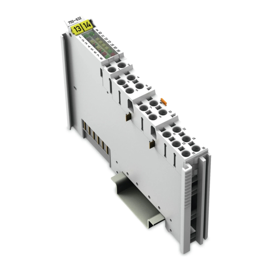
Page 19: View
Pos : 27 /Serie 750 ( WAGO-I/O-SYST EM)/Ger ätebesc hrei bung/Ansic ht/Sonder klemmen/Ansic ht 750- 0632 - Abb. @ 16\mod_1372397542615_21.doc x @ 125090 @ @ 1 Figure 2: View Pos : 28 /Serie 750 ( WAGO-I/O-SYST EM)/Ger ätebesc hrei bung/Ansic ht/Ansic ht Push-in Cag eClamp® _Legende mit LEDs @ 15\mod_1370852562803_21.doc x @ 122213 @ @ 1 Table 5: Legend for Figure “View”... -
Page 20: Connectors
Pos : 32.3 /Serie 750 (WAGO-I/O-SYST EM)/Wic htige Erläuterungen/Sicherheits- und sonstig e Hinweis e/Achtung/Achtung: ESD - Auf g ute Erdung der U mgebung ac hten! @ 7\mod_1266318538667_21.doc x @ 50708 @ @ 1 Ensure that the environment is well grounded! The devices are equipped with electronic components that may be destroyed by electrostatic discharge. -
Page 21: Power Jumper Contacts/Field Supply
Power Jumper Contacts/Field Supply Pos : 35.1 /Serie 750 (WAGO-I/O-SYST EM)/Wic htige Erläuterungen/Sicherheits- und sonstig e Hinweis e/Vorsic ht/Vorsicht: Verl etz ungsgefahr durc h s charfkantige M ess er kontakte! @ 6\mod_1256193279401_21.doc x @ 43414 @ @ 1 Risk of injury due to sharp-edged blade contacts! The blade contacts are sharp-edged. -
Page 22: Push-In Cage Clamp ® Connectors
750-632 Proportional Valve Module Pos : 37 /Serie 750 ( WAGO-I/O-SYST EM)/Ger ätebesc hrei bung/Ansc hl üss e/Pus h-in C AGE C LAMP®- Ans chl üss e - Ü bersc hrift 3 @ 15\mod_1370519905692_21.doc x @ 122018 @ 3 @ 1 ®... -
Page 23: Push-In Cage Clamp ® Connectors 750-632/000-100
WAGO-I/O-SYSTEM 750 Device Description 750-632 Proportional Valve Module Pos : 40 /Serie 750 ( WAGO-I/O-SYST EM)/Ger ätebesc hrei bung/Ansc hl üss e/Sonder klemmen/Ansc hlüsse 750-0632/000- 100 @ 24\mod_1448526743566_21.doc x @ 196298 @ 4 @ 1 ® 4.2.3.2 Push-in CAGE CLAMP Connectors 750-632/000-100 ®... -
Page 24: Display Elements
Pos : 42 /All e Seri en (Allgemei ne Module)/Ü berschriften/N eue Ü berschriften/Ebene 2Anzeigeel emente - Ü bers chrift 2 @ 4\mod_1240984390875_21.doc x @ 31964 @ 2 @ 1 Display Elements Pos : 43 /Serie 750 ( WAGO-I/O-SYST EM)/Ger ätebesc hrei bung/Anz eigeelemente/Sonder klemmen/Anz eigeel emente 750- 0632 @ 13\mod_1353337966901_21.doc x @ 106512 @ @ 1 Figure 7: Display Elements Table 9: Legend for Figure “Display Elements”... - Page 25 WAGO-I/O-SYSTEM 750 Device Description 750-632 Proportional Valve Module Table 9: Legend for Figure “Display Elements” Channel Designation LED State Function Green Logic „1“ Signal status DI 1 Logic „0“ Green Logic „1“ Signal status DI 2 Logic „0“ Green No undervoltage...
-
Page 26: Schematic Diagram
Pos : 45 /All e Seri en (Allgemei ne Module)/Ü berschriften/N eue Ü berschriften/Ebene 2Sc hematisc hes Schaltbild - Übersc hrift 2 @ 4\mod_1240984441312_21.doc x @ 31967 @ 2 @ 1 Schematic Diagram Pos : 46 /Serie 750 ( WAGO-I/O-SYST EM)/Ger ätebesc hrei bung/Schematisc he Sc haltbil der/Sonderkl emmen/Sc hematisc hes Sc haltbild 750-0632 @ 15\mod_1371218368579_21.doc x @ 123180 @ 3 @ 1 4.4.1... -
Page 27: Schematic Diagram 750-632/000-100
Device Description 750-632 Proportional Valve Module Pos : 48 /Serie 750 ( WAGO-I/O-SYST EM)/Ger ätebesc hrei bung/Schematisc he Sc haltbil der/Sonderkl emmen/Sc hematisc hes Sc haltbild 750-0632/000- 100 @ 24\mod_1448547741377_21.doc x @ 196358 @ 3 @ 1 4.4.2 Schematic Diagram 750-632/000-100 Figure 9: Schematic Diagram 750-632/000-100 Pos : 49 /D okumentation allgemei n/Glieder ungs elemente/---Seitenwechs el--- @ 3\mod_1221108045078_0.doc x @ 21810 @ @ 1... -
Page 28: Technical Data
Pos : 50 /All e Seri en (Allgemei ne Module)/Ü berschriften/N eue Ü berschriften/Ebene 2T ec hnis che D aten - Ü bersc hrift 2 @ 3\mod_1232967587687_21.doc x @ 26924 @ 2 @ 1 Technical Data Pos : 51 /Serie 750 ( WAGO-I/O-SYST EM)/Ger ätebesc hrei bung/T echnisc he Daten/Sonder kl emmen/T ec hnische D aten 750-0632 @ 15\mod_1371220399952_21.doc x @ 123195 @ 3333333 @ 1 4.5.1 Device Data Table 10: Technical Data ‒... -
Page 29: Outputs
WAGO-I/O-SYSTEM 750 Device Description 750-632 Proportional Valve Module 4.5.5 Outputs Table 14: Technical Data ‒ Outputs Property Value/Dimension Number and type 2 channels, PWM signal, bipolar (A+, A− and B+, B−) Features Output stage output, short-circuit-proof and protected against overload by... -
Page 30: Wiring
Device Description WAGO-I/O-SYSTEM 750 750-632 Proportional Valve Module 4.5.6 Wiring Table 16: Technical Data ‒ Wiring Property Value/Dimension ® Connection technology Push-in CAGE CLAMP Wire sizes solid 0.08 mm² … 1.5 mm²/AWG 28 … 16 fine-stranded 0.25 mm² … 1.5 mm²/AWG 22 … 16 Coil connections A+/A and B+/B-: 1.5 mm²/AWG 16... -
Page 31: Approvals
Approvals Pos : 54 /Serie 750 ( WAGO-I/O-SYST EM)/Ger ätebesc hrei bung/Z ulass ungen/Allgemei n/Z ulass ung Bus kl emme 750- xxxx Allgemei n, Standardvers. und Var. /000-100 - Ei nleitung @ 25\mod_1453200131878_21.doc x @ 198568 @ @ 1 The following approvals have been granted for the standard version of the 750- 632 I/O module and for the 750-632/000-100 version: Pos : 55 /All e Seri en (Allgemei ne Module)/Z ulassungen/Standardz ulassungen/C E (Konformi täts kennz eichnung) @ 3\mod_1224494777421_21.doc x @ 24276 @ @ 1... -
Page 32: Standards And Guidelines
Standards and Guidelines Pos : 69 /Serie 750 ( WAGO-I/O-SYST EM)/Ger ätebesc hrei bung/N ormen und Ric htlini en/Nor men und Ric htlini en Bus kl emme 750-xxxx, Standardversi on und Variante /000- 100 @ 25\mod_1454506326125_21.doc x @ 199948 @ @ 1... -
Page 33: Function Description
Pos : 78 /All e Seri en (Allgemei ne Module)/Ü berschriften/N eue Ü berschriften/Ebene 1F unkti ons besc hrei bung - Ü bersc hrift 1 @ 4\mod_1239025975389_21.doc x @ 30003 @ 1 @ 1 Function Description Pos : 79 /Serie 750 ( WAGO-I/O-SYST EM)/F unktions beschr eibung/Funkti onsbesc hrei bung 750-0632 @ 13\mod_1353408395858_21.doc x @ 106540 @ 23323332333333455455344423233334433 @ 1 The I/O module can be operated with all compatible fieldbus couplers/controllers from the WAGO-I/O-SYSTEM 750. -
Page 34: Operating Mode With Two Valves
(4-wire) (3-wire) (4-wire) (3-wire) Uni- Uni- Uni- Uni- Uni- Uni- direc- direc- direc- direc- direc- direc- direc- direc- tional tional tional tional tional tional tional tional Functionality is only supported by version 750-632/000-100. Manual Version 1.3.0, valid from FW/HW-Version 01/01... -
Page 35: Specifying The Setpoint Value
WAGO-I/O-SYSTEM 750 Function Description 750-632 Proportional Valve Module Specifying the Setpoint Value The control current provided by the I/O module can be directly specified in the process image (output) via a setpoint value. The current actual value is depicted by the I/O module in the process image (input) as the value of the current. -
Page 36: Specifying Setpoint Value: Operating Mode With Two Valves
Function Description WAGO-I/O-SYSTEM 750 750-632 Proportional Valve Module 5.2.2 Specifying Setpoint Value: Operating Mode with Two Valves Table 21: Operating Mode with Two Valves Setpoint Coil control Setpoint Control value range value, value range reference Valve n One coil −100 … < 0 % 0 % unidirectional 0 …... -
Page 37: Functions For The Setpoint Value Control
WAGO-I/O-SYSTEM 750 Function Description 750-632 Proportional Valve Module Functions for the Setpoint Value Control The I/O module offers the following functions, to be explained later: 5.3.1 “Automatic mode” In “Automatic Mode”, the I/O module approaches the specified setpoint value automatically with the selected ramp. -
Page 38: Jog Mode
Function Description WAGO-I/O-SYSTEM 750 750-632 Proportional Valve Module 5.3.2 “Jog Mode” In this function, the I/O module changes the setpoint value until an applied signal is canceled. For example, a drive runs at a fixed speed in a fixed direction until a corresponding button is released. -
Page 39: Tip Mode
WAGO-I/O-SYSTEM 750 Function Description 750-632 Proportional Valve Module 5.3.3 “Tip Mode” The “Tip mode” function is a variant of the “Jog mode” function. In this case, the change in current is not controlled by level. At a rising edge, the current is increased or decreased for a parameterizable time period. -
Page 40: Hold
Function Description WAGO-I/O-SYSTEM 750 750-632 Proportional Valve Module 5.3.4 “HOLD” During a ramp, the current level can be maintained using the “HOLD” function. Figure 13: “HOLD” Function Table 26: “HOLD” Function Event Description/Behavior SPL_EN is set to “1”. Setpoint value is increased. -
Page 41: Stop
WAGO-I/O-SYSTEM 750 Function Description 750-632 Proportional Valve Module 5.3.5 “STOP” The “STOP” function can be achieved during operations automatically guided by the I/O module by specifying “0” as the setpoint value. As a result, the I/O module approaches this setpoint value at a speed according to the currently valid ramp. -
Page 42: End Stop Behavior
Ramp stops. Present current level is achieved. maintained. 5.3.6 End Stop Behavior The end stop behavior can be configured from the tab or WAGO-I/O-CHECK. The respective parameters are described below: Table 28: End Stop Behavior Parameter Description Hold current value. -
Page 43: 5.3.6.1.1 Approach End Stop Value
WAGO-I/O-SYSTEM 750 Function Description 750-632 Proportional Valve Module 5.3.6.1.1 Approach End Stop Value Figure 15: Approach End Stop Value Table 29: Approach End Stop Value Event Description/Behavior Set SPL_EN to “1” “Automatic mode” is activated. Change setpoint value Ramp starts. - Page 44 Function Description WAGO-I/O-SYSTEM 750 750-632 Proportional Valve Module Change the setpoint manually! The end stop value must be reached before the setpoint can be manually changed in JOG mode! Configuring the end stop value correctly! The I/O module does not consider whether the end stop has been configured correctly.
-
Page 45: Hold Current Value ("Freeze")
WAGO-I/O-SYSTEM 750 Function Description 750-632 Proportional Valve Module 5.3.6.1.2 Hold Current Value (“Freeze”) Figure 16: Hold Current Value (“Freeze”) Table 30: Hold Current Value (“Freeze”) Event Description/Behavior Set SPL_EN to “1” “Automatic mode” is activated. Change setpoint value Ramp starts. -
Page 46: End Stop Behavior In "Jog Mode" And "Tip Mode
Function Description WAGO-I/O-SYSTEM 750 750-632 Proportional Valve Module 5.3.6.2 End Stop Behavior in “JOG Mode” and “TIP Mode” The end stop behavior is divided into: • Approach end stop value • Hold current value (“Freeze”) 5.3.6.2.1 Approach End Stop Value... -
Page 47: Table 31: Approach End Stop Value
WAGO-I/O-SYSTEM 750 Function Description 750-632 Proportional Valve Module Table 31: Approach End Stop Value Event Description/Behavior Set SPL_EN to “0” “JOG mode” is activated. Present current level is maintained. Set JOG_POS to “1” Present current level is increased. Set JOG_POS to “0”... -
Page 48: Hold Current Value ("Freeze")
Function Description WAGO-I/O-SYSTEM 750 750-632 Proportional Valve Module 5.3.6.2.2 Hold Current Value (“Freeze”) Figure 18: Hold Current Value (“Freeze”) Table 32: Hold Current Value (“Freeze”) Event Description/Behavior Set SPL_EN to “0” “JOG mode” is activated. Present current level is maintained. -
Page 49: Substitute Value Strategy
The behavior can be configured as follows: • Section “Tables 50, 51 (Process Data Handling, Valve 1, Valve 2)” • Section “Configuration and Parameterization with WAGO-I/O-CHECK 5.3.7.1 Approach Substitute Value The substitute value can be approached in two ways: •... -
Page 50: Manual Mode In Case Of Error (Emergency Operation)
The behavior can be configured as follows: • Section “Tables 52, 53 (Output Stage Valve 1, Valve 2)” • Section “Configuration and Parameterization with WAGO-I/O-CHECK“ Manual Version 1.3.0, valid from FW/HW-Version 01/01... -
Page 51: Digital Inputs
WAGO-I/O-SYSTEM 750 Function Description 750-632 Proportional Valve Module Digital Inputs The functions • “Digital input” • “Jog mode” • “Tip mode” • “HOLD” • “STOP” • “End stop behavior” can be controlled via the digital inputs DI1 and DI2 using corresponding parameterization. -
Page 52: Generating Setpoint Values
Function Description WAGO-I/O-SYSTEM 750 750-632 Proportional Valve Module 5.4.1 Generating Setpoint Values The setpoint value can be influenced by various functions: • By direct setpoint value specification (see section “Specifying Setpoint Values”), • By activating the Jog mode or Tip mode (see the section “Functions”), and •... -
Page 53: Figure 19: Overview Of The Internal Information Flow
WAGO-I/O-SYSTEM 750 Function Description 750-632 Proportional Valve Module Figure 19: Overview of the Internal Information Flow Table 34: Legend – Overview of the Internal Information Flow Designation Explanation Setpoint value specification Ramp generator Linearization Valve adjustment Nominal current Dither generator Manual Version 1.3.0, valid from FW/HW-Version 01/01... -
Page 54: Function Block: Ramp Generator
Function Description WAGO-I/O-SYSTEM 750 750-632 Proportional Valve Module 5.5.1 Function Block: Ramp Generator The speed at which the electrical current follows the setpoint value specification is designated as the “ramp function”. The ramp generator serves, among other purposes, to protect the slower mechanical systems when the setpoint value is changed erratically. -
Page 55: Figure 21: Start Up Ramp 100% In 1 Ms
WAGO-I/O-SYSTEM 750 Function Description 750-632 Proportional Valve Module Table 35: Resolution of the Nominal Current Nominal Current Resolution (%) Resolution (mA) 1000 mA 0.01% 0.1 mA Table 36: Correlation: Resolution – Time Value (Input) Current after 1 ms Limit value... -
Page 56: Function Block: Linearization
Function Description WAGO-I/O-SYSTEM 750 750-632 Proportional Valve Module Figure 23: Start up Ramp 100% in 10,000 ms Table 37: Reference Values for Ramps Procedure Rising Ramps Falling Ramps Reference Value Direct specification Nominal current of setpoint value Setup mode Nominal current... -
Page 57: Function Block: Valve Adjustment
WAGO-I/O-SYSTEM 750 Function Description 750-632 Proportional Valve Module 5.5.3 Function Block: Valve Adjustment This function block is used to compensate for design-related differences between the magnets and the valve. The goal is to achieve the most linear connection possible between the process value and the volume flow. -
Page 58: Figure 27: Positive Overlap
Function Description WAGO-I/O-SYSTEM 750 750-632 Proportional Valve Module Positive overlap: The high overlap ensures the lowest possible leakage in • the zero position. This type of overlap is used most commonly in proportional valves. Figure 27: Positive Overlap Table 38: Types of overlap... -
Page 59: Exemplary Depiction Of The Characteristic Curve Compensation
WAGO-I/O-SYSTEM 750 Function Description 750-632 Proportional Valve Module 5.5.4.1 Exemplary Depiction of the Characteristic Curve Compensation The following image clarifies characteristic curve compensation by means of an example: Figure 28: Characteristic Curve Compensation In the top part of the image, the characteristic curve is shown for a valve with positive overlap. -
Page 60: Function Block: Dither Generator
Function Description WAGO-I/O-SYSTEM 750 750-632 Proportional Valve Module Table 39: Function Block: Nominal Current Variable Value Unit PA_NOMINAL_CURR 2000 Process value <Current> 5000 0.01% Target output current 1000 5.5.5 Function Block: Dither Generator Using this function block causes a reduction of the influence of static friction. - Page 61 WAGO-I/O-SYSTEM 750 Function Description 750-632 Proportional Valve Module Parameter #DG_RAMP_ON and #DG_RAMP_OFF The dither signal is only gradually supplied to the actual value during on and off switching. The temporal process is determined by switching a ramp on and off.
-
Page 62: Current Outputs For Valve Coils
Function Description WAGO-I/O-SYSTEM 750 750-632 Proportional Valve Module 5.5.6 Current Outputs for Valve Coils As soon as the ambient temperature increases in the I/O module, the nominal current is reduced according to the following diagram: Figure 29: Current Carrying Capacity Curve... -
Page 63: Process Image
Pos : 81 /All e Seri en (Allgemei ne Module)/Ü berschriften/N eue Ü berschriften/Ebene 1Proz ess abbil d - Ü bersc hrift 1 @ 4\mod_1240983067828_21.doc x @ 31942 @ 1 @ 1 Process Image Pos : 82 /Serie 750 ( WAGO-I/O-SYST EM)/Proz ess abbild Kl emmenbus /Sonder klemmen/Pr ozessabbild 750- 0632 @ 13\mod_1353409248142_21.doc x @ 106543 @ 23323322 @ 1 The process image differs depending on the type of fieldbus: All Fieldbuses (except PROFIBUS and PROFINET) 6.1.1... -
Page 64: Profibus And Profinet
Process Image WAGO-I/O-SYSTEM 750 750-632 Proportional Valve Module PROFIBUS and PROFINET 6.2.1 Operating Mode with One Valve Table 42: Process Image Process Image Input Output Byte 0 K-Bus-Statusbyte S0 Byte 0 RESERVED Byte 1 V1_STATUS Byte 1 V1_CONTROL Byte 2... -
Page 65: Table 45: Status Byte S0
WAGO-I/O-SYSTEM 750 Process Image 750-632 Proportional Valve Module Table 45: Status Byte S0 Status Byte S0 Bit 7 Bit 6 Bit 5 Bit 4 Bit 3 Bit 2 Bit 1 Bit 0 REG=0 ERR_CH2 ERR_CH1 ERR_MOD REG=1 REGCOM_UPSTREAM 0: Register communication disabled... -
Page 66: Table 47: Locking The Bits M_Up And M_Down
Process Image WAGO-I/O-SYSTEM 750 750-632 Proportional Valve Module Table 47: Locking the Bits M_UP and M_DOWN JOGPOS_ACK JOGNEG_ACK Action No change of value Falling ramp Rising ramp No change of value Table 48: Status Byte S1 Status Byte S1 Bit 7... -
Page 67: Representation Of Target And Actual Values
WAGO-I/O-SYSTEM 750 Process Image 750-632 Proportional Valve Module Representation of Target and Actual Values Table 50: Representation of Target and Actual Values Short Description Setpoint Value Actual Value Target value V1_TARGET, V1_ACTUAL, V2_TARGET V1_ACTUAL Data type INT16 INT16 (twos complement) -
Page 68: Mounting
I/O modules with fewer power contacts. Pos : 85.2 /Serie 750 (WAGO-I/O-SYST EM)/Wic htige Erläuterungen/Sicherheits- und sonstig e Hinweis e/Vorsic ht/Vorsicht: Verl etz ungsgefahr durc h s charfkantige M ess er kontakte! @ 6\mod_1256193279401_21.doc x @ 43414 @ @ 1 Risk of injury due to sharp-edged blade contacts! The blade contacts are sharp-edged. -
Page 69: Inserting And Removing Devices
Mounting 750-632 Proportional Valve Module Pos : 85.6 /Serie 750 (WAGO-I/O-SYST EM)/M ontieren/D emontieren/Geräte einfüg en und entfer nen - Ü berschrift 2 @ 3\mod_1231768483250_21.doc x @ 25950 @ 2 @ 1 Inserting and Removing Devices Pos : 85.7 /All e Seri en ( Allgemei ne Module)/Sicherheits- und s ons tige Hi nweis e/Ac htung/Achtung: Arbeiten an Ger äten nur s pannungsfr ei durc hführ en! @ 6\mod_1256193963573_21.doc x @ 43426 @ @ 1 Perform work on devices only if they are de-energized! Working on energized devices can damage them. -
Page 70: Removing The I/O Module
Mounting WAGO-I/O-SYSTEM 750 750-632 Proportional Valve Module Pos : 85.10 /Serie 750 ( WAGO-I/O-SYST EM)/Monti eren/D emonti eren/Bus kl emme entfer nen @ 4\mod_1239169375203_21.doc x @ 30334 @ 3 @ 1 7.2.2 Removing the I/O Module Remove the I/O module from the assembly by pulling the release tab. -
Page 71: Connect Devices
Connect Devices Pos : 88 /Serie 750 ( WAGO-I/O-SYST EM)/Ans chli eßen/Leiter an C AGE C LAM P ans chli eßen ( allgemei n) - Übersc hrift 2 und Text @ 3\mod_1225448660171_21.doc x @ 24928 @ 2 @ 1 ®... -
Page 72: Power Supply For Marine Applications
Pos : 90 /Serie 750 ( WAGO-I/O-SYST EM)/Ans chli eßen/Eins peisekonz epte/Ei nspeis ung 750- 632 bei Ei nsatz i m Sc hiffs bereic h - Ü bersc hrift 2 und Inhalt @ 24\mod_1446133712717_21.doc... -
Page 73: Connection Examples 750-632
Connect Devices 750-632 Proportional Valve Module Pos : 92 /Serie 750 ( WAGO-I/O-SYST EM)/Ans chli eßen/Anschl uss beispi ele 750- 632 - Ü berschrift 2 @ 25\mod_1453384502512_21.doc x @ 198899 @ 2 @ 1 Connection Examples 750-632 Pos : 93 /Serie 750 ( WAGO-I/O-SYST EM)/Ans chli eßen/Anschl uss beispi ele/Sonderkl emmen/Ansc hluss beispi el 750-0632 @ 16\mod_1375346537273_21.doc x @ 127440 @ 333 @ 1 8.3.1... -
Page 74: Connection Example 3: 1 Valve (3-Wire)
Connect Devices WAGO-I/O-SYSTEM 750 750-632 Proportional Valve Module 8.3.3 Connection Example 3: 1 Valve (3-Wire) Figure 37: Connection Example 3: 1 Valve (3-Wire) Pos : 94 /D okumentation allgemei n/Glieder ungs elemente/---Seitenwechs el--- @ 3\mod_1221108045078_0.doc x @ 21810 @ @ 1 Manual Version 1.3.0, valid from FW/HW-Version 01/01... -
Page 75: Connection Examples 750-632/000-100
Connect Devices 750-632 Proportional Valve Module Pos : 95 /Serie 750 ( WAGO-I/O-SYST EM)/Ans chli eßen/Anschl uss beispi ele 750- 632/000- 100 - Ü berschrift 2 @ 25\mod_1453384546113_21.doc x @ 198902 @ 2 @ 1 Connection Examples 750-632/000-100 Pos : 96 /Serie 750 ( WAGO-I/O-SYST EM)/Ans chli eßen/Anschl uss beispi ele/Sonderkl emmen/Ansc hluss beispi el 750-0632/000- 100 @ 24\mod_1449839616408_21.doc x @ 197048 @ 33 @ 1 8.4.1... - Page 76 Pos : 101 /Serie 750 (WAGO-I/O-SYST EM)/Wichtige Erläuter ung en/Sic her heits- und s onstige Hinweise/Hinweis/Hi nweis : Ver bes ser n der Sc hirmung durch großfl ächige Aufl age! @ 17\mod_1380611076998_21.doc x @ 133233 @ @ 1...
-
Page 77: Commissioning
Commissioning Pos : 104 /Alle Serien (Allgemei ne M odul e)/Ü bersc hriften/Neue Ü bersc hriften/Ebene 2Konfigurier en und Par ametrieren mit WAGO-I/O-CHEC K - Ü berschrift 2 @ 10\mod_1312356647294_21.doc x @ 75660 @ 2 @ 1 Configuration and Parameterization with WAGO-I/O-CHECK Pos : 105 /Serie 750 (WAGO-I/O-SYST EM)/In Betri eb nehmen/Par ametrieren mit WAGO-I/O-CHEC K/Konfiguri eren und Parametrieren mi t WAGO I/O-CHEC K 750-0632 @ 15\mod_1371224393000_21.doc x @ 123202 @ 3455445555555544 @ 1... -
Page 78: Figure 40: Wago-I/O-Check User Interface
Commissioning WAGO-I/O-SYSTEM 750 750-632 Proportional Valve Module In order to open specific parameterization dialogs for the I/O module, proceed as follows: Right click on the I/O module. Select the Settings menu item (see following figure Figure 40: WAGO-I/O-CHECK User Interface The parameterization dialog opens. -
Page 79: Parameterization Dialog
WAGO-I/O-SYSTEM 750 Commissioning 750-632 Proportional Valve Module 9.1.1 Parameterization Dialog The parameterization dialog is divided into the following areas: Figure 41: Parameterization Dialog for the I/O Module Table 52: Legend for the “Parameterization Dialog for the I/O Module” Number Area... -
Page 80: Toolbar
Commissioning WAGO-I/O-SYSTEM 750 750-632 Proportional Valve Module 9.1.1.1 Toolbar The toolbar is divided into the following areas in the parameterization dialog for the I/O module: • Main menu • Application menu Manual Version 1.3.0, valid from FW/HW-Version 01/01... -
Page 81: 9.1.1.1.1 Main Menu
WAGO-I/O-SYSTEM 750 Commissioning 750-632 Proportional Valve Module 9.1.1.1.1 Main Menu The toolbar in the main menu contains the following buttons: Figure 42: Buttons in the Main Menu Table 53: Buttons on the Main Menu Button Function Description [Disconnect] Interrupts an existing connection to the... -
Page 82: 9.1.1.1.2 Application Menu
Commissioning WAGO-I/O-SYSTEM 750 750-632 Proportional Valve Module 9.1.1.1.2 Application Menu The application menu is called up via the blue button to the left in the toolbar, and contains the following buttons: Figure 43: Buttons in the Application Menu Table 54: Buttons in the Application Menu... -
Page 83: Navigation Area
WAGO-I/O-SYSTEM 750 Commissioning 750-632 Proportional Valve Module 9.1.1.2 Navigation Area In the navigation area, there are eight different buttons that can be used to configure the I/O module: • “Operating Mode” menu item • “Module Parameters” menu item • “Digital Inputs” menu item •... -
Page 84: 9.1.1.3.1 "Operation Mode" Menu Item
Commissioning WAGO-I/O-SYSTEM 750 750-632 Proportional Valve Module 9.1.1.3.1 “Operation Mode” Menu Item Individual variants can be selected using this menu item: Figure 44: “Operation Mode” Menu Item Table 55: “Operating Mode” – Settings Menu Item Option Valve 1 Valve 2... -
Page 85: Figure 45: Operation Mode" Menu Item (750-632/000-100)
WAGO-I/O-SYSTEM 750 Commissioning 750-632 Proportional Valve Module The I/O module 750-632/000-100 has advanced setting possibillities. These are described below: Figure 45: Operation Mode” Menu Item (750-632/000-100) Table 56: “Operating Mode” – Advanced Setting Menu Item Option Valve 1 Valve 2... -
Page 86: 9.1.1.3.2 "Module Parameters" Menu Item
Commissioning WAGO-I/O-SYSTEM 750 750-632 Proportional Valve Module 9.1.1.3.2 “Module Parameters” Menu Item Various I/O module parameters can be set using this menu item: Figure 46: “Module Parameters” Menu Item Table 57: “Module parameters” menu item Option Description Tipp Mode TIP Time The time period for TIP mode can be defined. - Page 87 WAGO-I/O-SYSTEM 750 Commissioning 750-632 Proportional Valve Module Table 57: “Module parameters” menu item Option Description Actual Value Selector The user can select here in what format the actual value is output. The (Valve 1/Valve 2) “with filter” information specifies that the actual value is filtered with activated “Dither Function”.
-
Page 88: 9.1.1.3.3 "Digital Inputs" Menu Item
Commissioning WAGO-I/O-SYSTEM 750 750-632 Proportional Valve Module 9.1.1.3.3 “Digital Inputs” Menu Item The digital inputs 1 and 2 can be parameterized using this menu item: Figure 47: “Digital Inputs” Menu Item Table 58: “Digital Inputs” Menu Item Option Description Functional Assignment... -
Page 89: 9.1.1.3.4 "Ramp Settings" Menu Item
WAGO-I/O-SYSTEM 750 Commissioning 750-632 Proportional Valve Module 9.1.1.3.4 “Ramp Settings” Menu Item The individual ramps can be selected and parameterized for each valve using this menu item: Figure 48: “Ramp Settings” Menu Item Manual Version 1.3.0, valid from FW/HW-Version 01/01... -
Page 90: Table 59: "Ramp Settings" Menu Item
Commissioning WAGO-I/O-SYSTEM 750 750-632 Proportional Valve Module Table 59: “Ramp Settings” Menu Item Option Description Ramp Selection Nominal Value Ramp The selection of a ramp here can also be changed using the “Operation” menu item. Parameters This ramp is a fixed ramp. This selection cannot be changed using the “Operation”... -
Page 91: 9.1.1.3.5 "Dither Generator" Menu Item
WAGO-I/O-SYSTEM 750 Commissioning 750-632 Proportional Valve Module 9.1.1.3.5 “Dither Generator” Menu Item The “Dither generator” can be parameterized using this menu item. The static friction as well as the response threshold and hysteresis can be significantly reduced for each valve. Dithering can be switched off at low PWM frequencies. -
Page 92: 9.1.1.3.6 "Valve Adjustment" Menu Item
Commissioning WAGO-I/O-SYSTEM 750 750-632 Proportional Valve Module 9.1.1.3.6 “Valve Adjustment” Menu Item This menu item can be used for each valve to compensate for design-related differences between the magnets and the valve. Figure 50: “Valve Adjustment” Menu Item Table 61: “Valve Adjustment” Menu Item... -
Page 93: 9.1.1.3.7 "Linearization" Menu Item
WAGO-I/O-SYSTEM 750 Commissioning 750-632 Proportional Valve Module 9.1.1.3.7 “Linearization” Menu Item This menu item can compensate for static nonlinearities in each valve, which can occur in the downstream actuators. Figure 51: “Linearization” Menu Item Table 62: “Linearization” Menu Item Option... -
Page 94: 9.1.1.3.8 "Position" Menu Item
Commissioning WAGO-I/O-SYSTEM 750 750-632 Proportional Valve Module 9.1.1.3.8 “Position” Menu Item Different parameters for the I/O module can be set using this menu item: Figure 52: “Position” Menu Item Table 63: “Position” Menu Item Option Description Valve set point Current The setpoint value can be entered in relation to the nominal current (see “Valve adjustment”... -
Page 95: Diagnostics Area
WAGO-I/O-SYSTEM 750 Commissioning 750-632 Proportional Valve Module Table 63: “Position” Menu Item Option Description Diagnosis Group errors are displayed here. State The current status is displayed here. 9.1.1.4 Diagnostics Area In the diagnostics area, the obtained acyclic mailbox diagnostics are displayed. -
Page 96: Diagnostics
Pos : 107 /Alle Serien (Allgemei ne M odul e)/Ü bersc hriften/Neue Ü bersc hriften/Ebene 1Diag nose - Übersc hrift 1 @ 4\mod_1240831069471_21.doc x @ 31372 @ 1 @ 1 Diagnostics Pos : 108 /Serie 750 (WAGO-I/O-SYST EM)/Diagnos e/Bus klemmen/Diagnos e 750- 0632 @ 16\mod_1372456739470_21.doc x @ 125160 @ 222223333322 @ 1 10.1 Range Overrun by the Setpoint Value The range for the setpoint values is limited to +/-100%. -
Page 97: Undervoltage, Short Circuit, Wire Break, Overtemperature
WAGO-I/O-SYSTEM 750 Diagnostics 750-632 Proportional Valve Module 10.5 Undervoltage, Short Circuit, Wire Break, Overtemperature 10.5.1 Undervoltage As soon as a undervoltage occurs, the output stage is automatically switched off. The LEDs for “Status channel A”, ”Status channel B”, and “General I/O module error”... -
Page 98: Short Circuit
Diagnostics WAGO-I/O-SYSTEM 750 750-632 Proportional Valve Module 10.5.2 Short Circuit As soon as a short circuit occurs, the output stage is automatically switched off. The LEDs for “Status channel A” and “Status channel B” light up red. The status bit READY is set to “0”. The bits 1, 2, and 6 in the status byte of the internal data bus are set to “1”. -
Page 99: Switching Outputs Back On
WAGO-I/O-SYSTEM 750 Diagnostics 750-632 Proportional Valve Module • If a temperature of 97°C is overrun or underrun, then a warning diagnostic message is generated. • If a temperature of 102°C is overrun or underrun, then a switch off diagnostic message is generated. -
Page 100: Diagnostics Via Leds
Diagnostics WAGO-I/O-SYSTEM 750 750-632 Proportional Valve Module 10.6 Diagnostics via LEDs Table 64: Diagnostics via LEDs LED State Explanation Cause Remedy Undervoltage Check supply voltage. Short circuit, wire break, Check wiring. 4, 6 Channel error overload Overtemperature Check temperature, note “Current Reduction”... -
Page 101: Diagnostics Via Process Image
WAGO-I/O-SYSTEM 750 Diagnostics 750-632 Proportional Valve Module 10.7 Diagnostics via Process Image Table 65: Diagnostics via Process Image State Explanation Cause Remedy Undervoltage Check supply voltage. Short circuit, wire break, Check wiring. overload S1.READY 0 Channel error Overtemperature Check temperature, note “Current Reduction”... -
Page 102: Appendix
(via Mailbox 2.0) Transmit data Figure 55: Communication via Mailbox 2.0 Example: A sender wants to transfer 10 bytes (the character string "Hello Wago") to a receiver via a 4-byte wide channel. 11.1.1 Message The Mailbox 2.0 method packages the data in messages. A message contains a header and user data. -
Page 103: Transmission Channel
WAGO-I/O-SYSTEM 750 Appendix 750-632 Proportional Valve Module Structure of the simple header: Table 66: Structure of the Simple Header Simple header Bit 7 Bit 6 Bit 5 Bit 4 Bit 3 Bit 2 Bit 1 Bit 0 Length Data element length max. 127 bytes... -
Page 104: The Handshake Byte
Appendix WAGO-I/O-SYSTEM 750 750-632 Proportional Valve Module 11.1.2.1 The Handshake Byte In general, a distinction is made between Control(C) and Toggle(T) mode (bit 7). The Control mode is used to synchronize the subscribers. The Toggle mode is used to exchange data. -
Page 105: Communication Phases
WAGO-I/O-SYSTEM 750 Appendix 750-632 Proportional Valve Module 11.1.3 Communication Phases The Mailbox 2.0 mechanism defines two communication phases: • Synchronization • Data exchange Only after successful synchronization from sender to receiver the actual user data can be exchanged. 11.1.3.1 Synchronization In the synchronization phase, the handshake byte is used in Control mode. -
Page 106: 11.1.3.1.2 Acknowledgement
Appendix WAGO-I/O-SYSTEM 750 750-632 Proportional Valve Module 11.1.3.1.2 Acknowledgement The following acknowledgements are defined: Table 70: Acknowledgement Value Explanation Description INVALID Signals that the receiver has not started operations again after a reset. HOLD ACKNOWLEDGE Signal or confirmation that the channel is ready, but data is not currently being transferred (e.g. -
Page 107: 11.1.3.1.4 Finite Automation
WAGO-I/O-SYSTEM 750 Appendix 750-632 Proportional Valve Module 11.1.3.1.4 Finite Automation Synchronization follows the chart below. Figure 57: Finite Automation Manual Version 1.3.0, valid from FW/HW-Version 01/01... -
Page 108: Data Exchange
Appendix WAGO-I/O-SYSTEM 750 750-632 Proportional Valve Module 11.1.3.2 Data Exchange In the data exchange phase, the handshake byte is used in Toggle mode. Because a message is normally larger than the data part of the transmission channel, the message must be transferred in several cycles (fragmentation). -
Page 109: 11.1.3.2.1 Example
WAGO-I/O-SYSTEM 750 Appendix 750-632 Proportional Valve Module 11.1.3.2.1 Example The following example shows use of the transmission channel during a send operation (no full-duplex transmission): Figure 58: Example of Send Operation Pos : 112 /Dokumentati on allgemei n/Gli ederungsel emente/---Seitenwec hs el--- @ 3\mod_1221108045078_0.doc x @ 21810 @ @ 1 Manual Version 1.3.0, valid from FW/HW-Version 01/01... -
Page 110: Protocols Supported By Mailbox 2.0
Appendix WAGO-I/O-SYSTEM 750 750-632 Proportional Valve Module Pos : 113 /Alle Serien (Allgemei ne M odul e)/Mail boxkommuni kation/M ailbox 2.0 - Protokolle - Ei nleitung @ 16\mod_1371735374838_21.doc x @ 123816 @ 2 @ 1 11.2 Protocols Supported by Mailbox 2.0 Messages can be exchanged between different devices using the Mailbox 2.0... -
Page 111: Protocol 0X81 (Diagnostics)
WAGO-I/O-SYSTEM 750 Appendix 750-632 Proportional Valve Module Table 75: Protocol 0x80, Structure of PDUs, Legend Description Description This byte is not used by this PDU Table number Register number Parameter, top byte (MSB) Parameter, bottom byte (LSB) Reply status: 0x00... -
Page 112: Table 78: Protocol 0X81, Structure Of Pdus, Legend
Appendix WAGO-I/O-SYSTEM 750 750-632 Proportional Valve Module Table 78: Protocol 0x81, Structure of PDUs, Legend Description Description This byte is not used by this PDU Event or error code, top byte (MSB) Event or error code, bottom byte (LSB) Event qualifier: Bit 7 …... -
Page 113: Diagnostics Via Mailbox
WAGO-I/O-SYSTEM 750 Appendix 750-632 Proportional Valve Module 11.3 Diagnostics via Mailbox 11.3.1 Channel Error Table 79: Channel Errors Error Chan- Event Qualifier Code Cause of Error Solution Mode Type Diagnostics of the output stage, Check 24 V supply. channel 1 Check for short circuit. - Page 114 Appendix WAGO-I/O-SYSTEM 750 750-632 Proportional Valve Module Table 79: Channel Errors Error Chan- Event Qualifier Code Cause of Error Solution Mode Type Range exceeded, setpoint value Smaller setpoint value, SINGLE WARN channel 2 equal to 100% Manual Version 1.3.0, valid from FW/HW-Version 01/01...
-
Page 115: General Errors
WAGO-I/O-SYSTEM 750 Appendix 750-632 Proportional Valve Module 11.3.2 General Errors Table 80: General Errors Chan- Event Qualifier Error Cause of Error Solution Mode Type Code Remedy the cause for APPDIS ERROR Group error, general error. individual errors. Check 24 V supply. -
Page 116: Communication Errors
Appendix WAGO-I/O-SYSTEM 750 750-632 Proportional Valve Module 11.3.3 Communication Errors Table 81: Channel Errors Error Chan- Event Qualifier Code Cause of Error Solution Mode Type bMbxInstance1_ Send error report to 3000 SINGLE ERROR RxExecDisabled_Err WAGO support bMbxInstance1_RxExec_ Send error report to... -
Page 117: Table 81: Channel Errors
WAGO-I/O-SYSTEM 750 Appendix 750-632 Proportional Valve Module Table 81: Channel Errors Error Chan- Event Qualifier Code Cause of Error Solution Mode Type bMbxInstance1_ Send error report to 3020 SINGLE ERROR RxSyncRdyStateGotErrCmd_ WAGO support bMbxInstance1_ Send error report to 3021 SINGLE ERROR... -
Page 118: Parameter, Reference
11.4 Parameter, Reference Pos : 119 /Serie 750 (WAGO-I/O-SYST EM)/Anhang/Anhang_Par ameter _Refer enz 750-632 @ 15\mod_1371453476510_21.doc x @ 123213 @ 3444443444444444 @ 1 All I/O module parameters are listed in the following as an overview. The parameters are saved in the form of registers having a size of two bytes (one word) each. -
Page 119: Table 85: Parameters, Table 31 (Status)
WAGO-I/O-SYSTEM 750 Appendix 750-632 Proportional Valve Module 11.4.1.2 Table 31 (Status) Table 85: Parameters, Table 31 (Status) Register Name, Bits Value/Range Description Type Explanation (Default) ST_ERROR, No error UINT16 Undervoltage Error No error Overtemperature Error (Warning) No error Overtemperature Error (Error) 3 …... -
Page 120: Tables 33, 34 (Di1, Di2)
Appendix WAGO-I/O-SYSTEM 750 750-632 Proportional Valve Module 11.4.1.4 Tables 33, 34 (DI1, DI2) Tables 33 and 34 are configured identically. As an example, Table 33 will be explained for DI1 here. Table 87: Parameters, Table 33 (DI1) Register Name, Bits... -
Page 121: Table
WAGO-I/O-SYSTEM 750 Appendix 750-632 Proportional Valve Module Table 87: Parameters, Table 33 (DI1) Register Name, Bits Value/Range Description Type Explanation (Default) HOLD Valve 1 Maintains current setpoint value. Note: This function is state-controlled: • If the input is activated, the “HOLD”... -
Page 122: Channel-Dependent Parameters
Appendix WAGO-I/O-SYSTEM 750 750-632 Proportional Valve Module 11.4.2.1 Channel-Dependent Parameters 11.4.2.2 Tables 50, 51 (Process Data Handling, Valve 1, Valve 2) Tables 50 and 51 are configured identically. As an example, Table 50 will be explained for Valve 1 here. -
Page 123: Tables 52, 53 (Output Stage, Valve 1, Valve 2)
WAGO-I/O-SYSTEM 750 Appendix 750-632 Proportional Valve Module 11.4.2.3 Tables 52, 53 (Output Stage, Valve 1, Valve 2) Tables 52 and 53 are configured identically. As an example, Table 52 will be explained for Valve 1 here. Table 90: Parameters, Table 52 (Output Stage, Valve 1) -
Page 124: Tables 54, 55 (Status Valve 1, Valve 2)
Appendix WAGO-I/O-SYSTEM 750 750-632 Proportional Valve Module 11.4.2.4 Tables 54, 55 (Status Valve 1, Valve 2) Tables 54 and 55 are configured identically. As an example, Table 54 will be explained for Valve 1 here. Table 91: Parameters, Table 54 (Status, Valve 1) -
Page 125: Tables 56, 57 (Ramp Generator, Valve 1, Valve 2)
WAGO-I/O-SYSTEM 750 Appendix 750-632 Proportional Valve Module 11.4.2.5 Tables 56, 57 (Ramp Generator, Valve 1, Valve 2) Tables 56 and 57 are configured identically. As an example, Table 56 will be explained for Valve 1 here. Table 92: Parameters, Table 56 (Ramp Generator, Valve 1) -
Page 126: Tables 58, 59 (Characteristic Curve Adjustment, Valve 1, Valve 2)126
Appendix WAGO-I/O-SYSTEM 750 750-632 Proportional Valve Module 11.4.2.6 Tables 58, 59 (Characteristic Curve Adjustment, Valve 1, Valve 2) Tables 58 and 59 are configured identically. As an example, Table 58 will be explained for Valve 1 here. Table 93: Parameters, Table 58 (Characteristic Curve Adjustment, Valve 1) - Page 127 WAGO-I/O-SYSTEM 750 Appendix 750-632 Proportional Valve Module Table 93: Parameters, Table 58 (Characteristic Curve Adjustment, Valve 1) Register Name, Bits Value/Range Description Type Explanation (Default) P12.x, INT16 0 … 15 (Default: Supporting point x[12] 2000) P12.y, INT16 0 … 15...
-
Page 128: Tables 60, 61 (Valve Adjustment, Valve 1, Valve 2)
Appendix WAGO-I/O-SYSTEM 750 750-632 Proportional Valve Module 11.4.2.7 Tables 60, 61 (Valve Adjustment, Valve 1, Valve 2) Tables 60 and 61 are identically structured. As an example, Table 60 will be explained for Valve 1 here. Table 94: Parameters, Table 60 (Valve Adjustment, Valve 1) -
Page 129: Table 95: Parameters, Table 62 (Dithering, Valve 1)
WAGO-I/O-SYSTEM 750 Appendix 750-632 Proportional Valve Module 11.4.2.8 Table 62, 63 (Dithering Valve 1, Valve 2) Tables 62 and 63 are identically structured. As an example, Table 62 will be explained for Valve 1 here. Table 95: Parameters, Table 62 (Dithering, Valve 1) -
Page 130: Tables 68, 69 (Current Controller, Valve 1, Valve 2)
INT16 0.01% of the nominal value The measured value filter is not active. Pos : 120 /Serie 750 (WAGO-I/O-SYST EM)/Anhang/Zahl endarstell ung 750- 0632 @ 16\mod_1379936209100_21.doc x @ 132490 @ 233 @ 1 Manual Version 1.3.0, valid from FW/HW-Version 01/01... -
Page 131: Number Representation
WAGO-I/O-SYSTEM 750 Appendix 750-632 Proportional Valve Module 11.5 Number Representation 11.5.1 Setpoint Value Table 98: Process Values – Setpoint Value View Setpoint Value [%] Decimal Hexadecimal -100 -10000 D8F0 -9000 DCD8 -8000 E0C0 -7000 E4A8 -6000 E890 -5000 EC78 -4000... -
Page 132: Table 99: Process Values - Actual Value
Appendix WAGO-I/O-SYSTEM 750 750-632 Proportional Valve Module Table 99: Process Values – Actual Value View Actual Value [mA] Decimal Hexadecimal -1000 -10,000 D8F0 -900 -9,000 DCD8 -800 -8,000 E0C0 -700 -7,000 E4A8 -600 -6,000 E890 -500 -5,000 EC78 -400 -4,000... -
Page 133: Use In Hazardous Environments
Pos : 122.1 /Alle Serien (Allgemeine M odul e)/Übersc hriften/Ebene 1Ei ns atz i n explosi onsgefähr deten Bereic hen - Ü berschrift 1 @ 3\mod_1224075191281_21.doc x @ 24084 @ 1 @ 1 Use in Hazardous Environments Pos : 122.2 /Serie 750 ( WAGO-I/O-SYST EM)/Ei ns atz i n Ex-Bereic hen/Einsatzbereic h Serie 750 @ 3\mod_1234272230203_21.doc x @ 27500 @ @ 1 The WAGO-I/O-SYSTEM 750 (electrical equipment) is designed for use in Zone 2 hazardous areas. -
Page 134: Marking Configuration Examples
Pos : 122.6 /Serie 750 ( WAGO-I/O-SYST EM)/Ei ns atz i n Ex-Bereic hen/Beispi elbedruc kung der ATEX- und IEC-Ex-z ugel ass enen Bus kl emmen g emäß CEN ELEC und IEC _2013 @ 14\mod_1360569228625_21.doc... -
Page 135: Figure 60: Text Detail - Marking Example For Approved I/O Modules According To Atex And Iecex
WAGO-I/O-SYSTEM 750 Use in Hazardous Environments 750-632 Proportional Valve Module Figure 60: Text Detail – Marking Example for Approved I/O Modules According to ATEX and IECEx. Manual Version 1.3.0, valid from FW/HW-Version 01/01... -
Page 136: Table 100: Description Of Marking Example For Approved I/O Modules According To Atex And Iecex
Use in Hazardous Environments WAGO-I/O-SYSTEM 750 750-632 Proportional Valve Module Table 100: Description of Marking Example for Approved I/O Modules According to ATEX and IECEx Marking Description TÜV 07 ATEX 554086 X Approving authority and certificate numbers IECEx TUN 09.0001 X... -
Page 137: Figure 61: Side Marking Example For Approved Ex I I/O Modules According To Atex And Iecex
750-632 Proportional Valve Module Pos : 122.8 /Serie 750 ( WAGO-I/O-SYST EM)/Ei ns atz i n Ex-Bereic hen/Beispi elbedruc kung der Ex-i- und IEC- Ex-i-zugel ass enen Bus kl emmen gemäß CEN ELEC und IEC_2013 @ 14\mod_1360569320118_21.doc x @ 111298 @ @ 1 Figure 61: Side Marking Example for Approved Ex i I/O Modules According to ATEX and IECEx. - Page 138 Use in Hazardous Environments WAGO-I/O-SYSTEM 750 750-632 Proportional Valve Module Table 101: Description of Marking Example for Approved Ex i I/O Modules According to ATEX and IECEx Marking Description TÜV 07 ATEX 554086 X Approving authority and certificate numbers IECEx TUN 09.0001X TÜV 12 ATEX 106032 X...
-
Page 139: Table 101: Description Of Marking Example For Approved Ex I I/O Modules According To Atex And Iecex
WAGO-I/O-SYSTEM 750 Use in Hazardous Environments 750-632 Proportional Valve Module Table 101: Description of Marking Example for Approved Ex i I/O Modules According to ATEX and IECEx Gases Equipment group: All except mining 3(1)G Category 3 (Zone 2) equipment containing a safety... -
Page 140: Marking For America According To Nec 500
WAGO-I/O-SYSTEM 750 750-632 Proportional Valve Module Pos : 122.10 /Seri e 750 ( WAGO-I/O-SYSTEM)/Einsatz in Ex- Ber eichen/Kennzeic hnung für Ameri ka gemäß N EC 500 - Ü berschrift 3 @ 3\mod_1224158423187_21.doc x @ 24188 @ 3 @ 1 12.1.2 Marking for America According to NEC 500 Pos : 122.11 /Seri e 750 ( WAGO-I/O-SYSTEM)/Einsatz in Ex- Ber eichen/Beis piel bedr uc kung gemäß... -
Page 141: Installation Regulations
WAGO-I/O-SYSTEM 750 Use in Hazardous Environments 750-632 Proportional Valve Module Pos : 122.13 /Alle Serien (Allgemeine M odule)/Ü bersc hriften/Ebene 2Errichtungsbesti mmung en - Übersc hrift 2 @ 3\mod_1232453624234_21.doc x @ 26370 @ 2 @ 1 12.2 Installation Regulations Pos : 122.14 /Alle Serien (Allgemeine M odule)/Ei nsatz i n Ex- Bereic hen/Errichtungsbesti mmungen Einl eitung _2013 @ 14\mod_1360582328318_21.doc x @ 111371 @ @ 1... -
Page 142: Special Conditions For Safe Use (Tüv 14 Atex 148929 X)
750-632 Proportional Valve Module Pos : 122.16 /Seri e 750 ( WAGO-I/O-SYSTEM)/Einsatz in Ex- Ber eichen/Bes ondere Bedingungen für den sicheren Ex-Betrieb g em. ATEX-Z ertifi kat TÜ V 14 AT EX 148929_X @ 21\mod_1416995371807_21.doc x @ 169118 @ 3 @ 1 12.2.1... -
Page 143: Special Conditions For Safe Use (Atex Certificate Tüv 12 Atex 106032 X)
750-632 Proportional Valve Module Pos : 122.18 /Seri e 750 ( WAGO-I/O-SYSTEM)/Einsatz in Ex- Ber eichen/Bes ondere Bedingungen für den sicheren Ex-Betrieb g em. ATEX-Z ertifi kat TÜ V 12 AT EX 106032x_2013_2 @ 15\mod_1368620479454_21.doc x @ 119782 @ 3 @ 1 12.2.2... -
Page 144: Special Conditions For Safe Use (Iec-Ex Certificate Tun 14.0035X)144
750-632 Proportional Valve Module Pos : 122.20 /Seri e 750 ( WAGO-I/O-SYSTEM)/Einsatz in Ex- Ber eichen/Bes ondere Bedingungen für den sicheren Ex-Betrieb g em. IEC- Ex-Zertifi kat TUN 14.0035 X_2014 @ 21\mod_1416995779884_21.doc x @ 169122 @ 3 @ 1 12.2.3 Special Conditions for Safe Use (IEC-Ex Certificate TUN 14.0035X) -
Page 145: Special Conditions For Safe Use (Iec-Ex Certificate Iecex Tun 12.0039 X)
750-632 Proportional Valve Module Pos : 122.22 /Seri e 750 ( WAGO-I/O-SYSTEM)/Einsatz in Ex- Ber eichen/Bes ondere Bedingungen für den sicheren Ex-Betrieb g em. IEC- Ex-Zertifi kat TUN 12.0039 X_2013_2 @ 15\mod_1368620821493_21.doc x @ 119790 @ 3 @ 1 12.2.4 Special Conditions for Safe Use (IEC-Ex Certificate IECEx TUN 12.0039 X) -
Page 146: Special Conditions For Safe Use According To Ansi/Isa
WAGO-I/O-SYSTEM 750 750-632 Proportional Valve Module Pos : 122.24 /Seri e 750 ( WAGO-I/O-SYSTEM)/Einsatz in Ex- Ber eichen/Errichtungs besti mmungen ANSI ISA 12.12.01_2013_2_für 750- 439, -633, -663/000-003 @ 21\mod_1417518338537_21.doc x @ 169812 @ 3 @ 1 12.2.5 Special Conditions for Safe Use according to ANSI/ISA 12.12.01... -
Page 147: List Of Figures
Figure 43: Buttons in the Application Menu ............82 Figure 44: “Operation Mode” Menu Item ............. 84 Figure 45: Operation Mode” Menu Item (750-632/000-100) ....... 85 Figure 46: “Module Parameters” Menu Item ............86 Figure 47: “Digital Inputs” Menu Item ..............88 Figure 48: “Ramp Settings”... - Page 148 List of Figures WAGO-I/O-SYSTEM 750 750-632 Proportional Valve Module Figure 49: “Dither Generator” Menu Item ............91 Figure 50: “Valve Adjustment” Menu Item ............92 Figure 51: “Linearization” Menu Item ..............93 Figure 52: “Position” Menu Item ................94 Figure 53: Response During Undervoltage ............97 Figure 54: Response During Short Circuit ............
-
Page 149: List Of Tables
Table 1: Versions ..................... 7 Table 2: Number Notation ..................10 Table 3: Font Conventions ..................10 Table 4: Compatibility List 750-632 ..............17 Table 5: Legend for Figure “View” ..............19 Table 6: Legend for Figure “Power Jumper Contacts” ......... 21 ®... - Page 150 List of Tables WAGO-I/O-SYSTEM 750 750-632 Proportional Valve Module Table 47: Locking the Bits M_UP and M_DOWN ..........66 Table 48: Status Byte S1 ..................66 Table 49: Status Byte S2 ..................66 Table 50: Representation of Target and Actual Values ........67 Table 51: Legend for Figure “Power Supply, Marine Applications”...
- Page 151 WAGO-I/O-SYSTEM 750 List of Tables 750-632 Proportional Valve Module Table 97: Parameters, Table 72 (Process Variables, Valve 1) ......130 Table 98: Process Values – Setpoint Value ............131 Table 99: Process Values – Actual Value ............131 Table 100: Description of Marking Example for Approved I/O Modules According to ATEX and IECEx ..............
- Page 152 Pos : 128 /Dokumentati on allgemei n/Ei nband/Ei nband Handbuc h - R üc ks eite 2015 @ 9\mod_1285229376516_21.doc x @ 64944 @ @ 1 WAGO Kontakttechnik GmbH & Co. KG Postfach 2880 • D-32385 Minden Hansastraße 27 • D-32423 Minden Phone: 05 71/8 87 –...
Need help?
Do you have a question about the 750-632 and is the answer not in the manual?
Questions and answers