
Subscribe to Our Youtube Channel
Related Manuals for WAGO 750 Series


Summary of Contents for WAGO 750 Series
- Page 1 Fieldbus Independent I/O Modules 2-Channel Up/Down Counter / 500 750-638(/xxx-xxx) Manual Version 1.0.3...
- Page 2 • General Copyright © 2006 by WAGO Kontakttechnik GmbH & Co. KG All rights reserved. WAGO Kontakttechnik GmbH & Co. KG Hansastraße 27 D-32423 Minden Phone: +49 (0) 571/8 87 – 0 Fax: +49 (0) 571/8 87 – 1 69 E-Mail: info@wago.com...
-
Page 3: Table Of Contents
2.1.1.4 Display elements................ 9 2.1.1.5 Schematic Diagram..............10 2.1.1.6 Technical Data ................. 11 2.1.1.7 Process Image ................12 2.1.1.8 Data Transfer ................13 2.1.1.9 Example: Set counter 1 on value 100 and count forward ..14 WAGO-I/O-SYSTEM 750 I/O Modules... -
Page 4: Important Comments
All other changes to the hardware and/or software and the non-conforming use of the components entail the exclusion of liability on part of WAGO Kon- takttechnik GmbH & Co. KG. -
Page 5: Symbols
More information References on additional literature, manuals, data sheets and internet pages. 1.3 Number Notation Number Code Example Note Decimal normal notation Hexadecimal 0x64 C notation Binary '100' within inverted commas, '0110.0100' nibble separated with dots WAGO-I/O-SYSTEM 750 I/O Modules... -
Page 6: Safety Notes
Do not use any contact spray. The spray may impair the functioning of the contact area. The WAGO-I/O-SYSTEM 750 and its components are an open system. It must only be assembled in housings, cabinets or in electrical operation rooms. Access must only be given via a key or tool to authorized qualified personnel. -
Page 7: O Modules
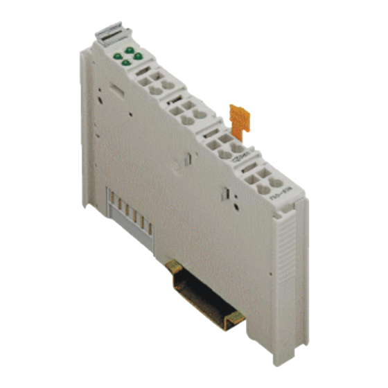
Potential 13 14 positive negative free Function Function impulses impulses signal DI 1 DI 2 Data contacts +DI 1 +DI 2 -DI 1 -DI 2 750-638 Power jumper contacts Fig. 2.1.1-1: 2-Channel Up/Down Counter 750-638 g063800e WAGO-I/O-SYSTEM 750 I/O Modules... -
Page 8: Description
An individual green status LED indicates the presence of a counting pulse at the channels. Communication with the coupler/controller is indicated by an additional green function LED. Field and system levels are electrically isolated. WAGO-I/O-SYSTEM 750 I/O Modules... -
Page 9: Display Elements
However, if such a case should occur, another supply module must be added. The up/down counter module can be operated with all couplers/controllers of the WAGO-I/O-SYSTEM 750 (except for the digital only versions 750-320, 750-323, 750-324 and 750-327). 2.1.1.4 Display elements... -
Page 10: Schematic Diagram
10 • 750-638(/xxx-xxx) [2-Channel Up/Down Counter / 500 Hz] Schematic Diagram 2.1.1.5 Schematic Diagram +DI 1 +DI 2 Logic 270pF Function 10nF 270pF -DI 1 -DI 2 750-638 Fig. 2.1.1-3: 2-Channel Up/Down Counter 750-638 g063801e WAGO-I/O-SYSTEM 750 I/O Modules... -
Page 11: Technical Data
Conformity Marking More Information Detailed references to the approvals are listed in the document "Overview Approvals WAGO-I/O-SYSTEM 750", which you can find on the CD ROM ELECTRONICC Tools and Docs (Item-No.: 0888-0412) or in the internet under: ! Documentation ! WAGO-I/O-SYSTEM 750 ! Sys- www.wago.com... -
Page 12: Process Image
0x0000 -> 0xFFFF backward mode Backwards 1: Backwards counter mode mode 0: Forward counter mode Lock 1: Locks the counter Counter 0: Counting mode Set Counter 1: Set counter with the set value 0: Counting mode reserved WAGO-I/O-SYSTEM 750 I/O Modules... -
Page 13: Data Transfer
If bit 0 in the control byte is set to "1" and the counter gets a next impulse after the maximum value (0xFFFF) or the minimum value (0x0000) is rea- ched, then the counter stays on the current value. WAGO-I/O-SYSTEM 750 I/O Modules... -
Page 14: Example: Set Counter 1 On Value 100 And Count Forward
4. Reset bit 5 (Set Counter) in the control byte C0. Bit 7 Bit 6 Bit 5 Bit 4 Bit 3 Bit 2 Bit 1 Bit 0 5. The counter value is shown in the input data D0, D1 of counter 1. 0x00 0x64 WAGO-I/O-SYSTEM 750 I/O Modules... - Page 15 0 = 0 *) 0x00 0x01 next impulse ....and so on *) if bit 0 in the control byte C0 is set on bit 0 = 1, the counter stays on the maximum value. WAGO-I/O-SYSTEM 750 I/O Modules...
- Page 16 WAGO Kontakttechnik GmbH & Co. KG Postfach 2880 • D-32385 Minden Hansastraße 27 • D-32423 Minden Phone: 05 71/8 87 – 0 Fax: 05 71/8 87 – 1 69 E-Mail: info@wago.com Internet: http://www.wago.com...
Need help?
Do you have a question about the 750 Series and is the answer not in the manual?
Questions and answers