
Subscribe to Our Youtube Channel
Related Manuals for WAGO 750-528


Summary of Contents for WAGO 750-528
- Page 1 Manual WAGO-I/O-SYSTEM 750 750-528 4DO 30V AC/DC 2.0A SSR Isolated 4-Channel Digital Output; 30 VAC/DC; 2.0 A; Solid-State; Isolated Version 1.0.0...
- Page 2 We wish to point out that the software and hardware terms as well as the trademarks of companies used and/or mentioned in the present manual are generally protected by trademark or patent. WAGO is a registered trademark of WAGO Verwaltungsgesellschaft mbH. Manual Version 1.0.0...
-
Page 3: Table Of Contents
WAGO-I/O-SYSTEM 750 Table of Contents 750-528 4DO 30V AC/DC 2.0A SSR Isolated Table of Contents Notes about this Documentation ............. 5 Validity of this Documentation..............5 Copyright ....................5 Symbols ....................6 Number Notation ..................8 Font Conventions ................... 8 Important Notes .................. - Page 4 Table of Contents WAGO-I/O-SYSTEM 750 750-528 4DO 30V AC/DC 2.0A SSR Isolated Connection Examples ................35 Use in Hazardous Environments ............36 Marking Configuration Examples ............37 7.1.1 Marking for Europe According to ATEX and IECEx ......37 7.1.2 Marking for the United States of America (NEC) and Canada (CEC) ....................
-
Page 5: Notes About This Documentation
This documentation is only applicable to the I/O module 750-528 (4DO 30V AC/DC 2.0A SSR Isolated). The I/O module 750-528 shall only be installed and operated according to the instructions in this manual and in the manual for the used fieldbus coupler or controller. -
Page 6: Symbols
Notes about this Documentation WAGO-I/O-SYSTEM 750 750-528 4DO 30V AC/DC 2.0A SSR Isolated Symbols Personal Injury! Indicates a high-risk, imminently hazardous situation which, if not avoided, will result in death or serious injury. Personal Injury Caused by Electric Current! Indicates a high-risk, imminently hazardous situation which, if not avoided, will result in death or serious injury. - Page 7 WAGO-I/O-SYSTEM 750 Notes about this Documentation 750-528 4DO 30V AC/DC 2.0A SSR Isolated Additional Information: Refers to additional information which is not an integral part of this documentation (e.g., the Internet). Manual Version 1.0.0...
-
Page 8: Number Notation
Notes about this Documentation WAGO-I/O-SYSTEM 750 750-528 4DO 30V AC/DC 2.0A SSR Isolated Number Notation Table 1: Number Notation Number Code Example Note Decimal Normal notation Hexadecimal 0x64 C notation Binary '100' In quotation marks, nibble separated '0110.0100' with dots (.) -
Page 9: Important Notes
2.1.1 Subject to Changes WAGO Kontakttechnik GmbH & Co. KG reserves the right to provide for any alterations or modifications. WAGO Kontakttechnik GmbH & Co. KG owns all rights arising from the granting of patents or from the legal protection of utility patents. -
Page 10: Technical Condition Of Specified Devices
These modules contain no parts that can be serviced or repaired by the user. The following actions will result in the exclusion of liability on the part of WAGO Kontakttechnik GmbH & Co. KG: •... -
Page 11: Safety Advice (Precautions)
WAGO-I/O-SYSTEM 750 Important Notes 750-528 4DO 30V AC/DC 2.0A SSR Isolated Safety Advice (Precautions) For installing and operating purposes of the relevant device to your system the following safety precautions shall be observed: Do not work on devices while energized! All power sources to the device shall be switched off prior to performing any installation, repair or maintenance work. - Page 12 Check if the voltage is positively isolated. Power from SELV/PELV power supply only! All field signals and field supplies connected to this I/O module (750-528) must be powered from SELV/PELV power supply(s)! Inadequate wire cross sections can cause temperature increases! To avoid increasing thermal risks, only use conductor cross-sections sufficient for the required maximum load current.
- Page 13 WAGO-I/O-SYSTEM 750 Important Notes 750-528 4DO 30V AC/DC 2.0A SSR Isolated Do not exceed the maximum total current for I/O modules (5 VDC) via data contacts! The maximum permissible total current for internal system supply of the I/O modules may not be exceeded. The permissible total current is specified in the technical data of the head station and power supply.
- Page 14 Important Notes WAGO-I/O-SYSTEM 750 750-528 4DO 30V AC/DC 2.0A SSR Isolated Do not reverse the polarity of connection lines! Avoid reverse polarity of data and power supply lines, as this may damage the devices involved. Avoid electrostatic discharge! The devices are equipped with electronic components that may be destroyed by electrostatic discharge when touched.
-
Page 15: Device Description
Use a supply module when an earth potential is needed for the subsequent I/O modules. The I/O Module 750-528 (4DO 30V AC/DC 2.0A SSR Isolated) passes the 24 V voltage through that it receives from an upstream I/O module or the head station via the power jumper contacts designed as blade contacts. -
Page 16: View
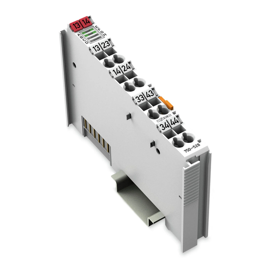
Device Description WAGO-I/O-SYSTEM 750 750-528 4DO 30V AC/DC 2.0A SSR Isolated View Figure 1: View Table 3: Legend for Figure “View” Pos. Description Details See Section Marking possibility with Mini- Status LEDs “Device Description” > “Display Elements” Data contacts “Device Description” > “Connectors”... -
Page 17: Connectors
WAGO-I/O-SYSTEM 750 Device Description 750-528 4DO 30V AC/DC 2.0A SSR Isolated Connectors 3.2.1 Data Contacts/Local Bus Communication between the fieldbus coupler/controller and the I/O modules as well as the system supply of the I/O modules is carried out via the local bus. The contacting for the local bus consists of 6 data contacts, which are available as self-cleaning gold spring contacts. -
Page 18: Power Jumper Contacts/Field Supply
The blade contacts are sharp-edged. Handle the I/O module carefully to prevent injury. Do not touch the blade contacts. The I/O module 750-528 has 2 self-cleaning power jumper contacts that receive and transmit power for the field side. The contacts on the left side of the I/O module are designed as blade contacts and those on the right side as spring contacts. - Page 19 WAGO-I/O-SYSTEM 750 Device Description 750-528 4DO 30V AC/DC 2.0A SSR Isolated Use supply modules for ground (earth)! The I/O module has no power jumper contacts for receiving and transmitting the earth potential. Use a supply module when an earth potential is needed for the subsequent I/O modules.
-
Page 20: Cage Clamp ® Connectors
Device Description WAGO-I/O-SYSTEM 750 750-528 4DO 30V AC/DC 2.0A SSR Isolated 3.2.3 CAGE CLAMP ® Connectors Figure 4: CAGE CLAMP ® Connectors Table 5: Legend for Figure “CAGE CLAMP ® Connectors” Channel Designation Connection Function DO 1.1 Output DO 1: Potential-free contact DO 1.2... -
Page 21: Display Elements
WAGO-I/O-SYSTEM 750 Device Description 750-528 4DO 30V AC/DC 2.0A SSR Isolated Display Elements Figure 5: Display Elements Table 6: Legend for Figure “Display Elements” Channel Designation Function Status DO 1 Channel status, output DO 1 Status DO 2 Channel status, output DO 2... -
Page 22: Technical Data
Device Description WAGO-I/O-SYSTEM 750 750-528 4DO 30V AC/DC 2.0A SSR Isolated Technical Data 3.5.1 Device Data Table 7: Technical Data ‒ Device Width 12 mm Height from upper edge of DIN-rail 64 mm Depth 100 mm Weight 48.5 g 3.5.2 Digital Outputs Table 8: Technical Data ‒ Digital Outputs... -
Page 23: Field Supply
WAGO-I/O-SYSTEM 750 Device Description 750-528 4DO 30V AC/DC 2.0A SSR Isolated 3.5.3 Field Supply Table 9: Technical Data − Field Supply Field supply voltage (max.) SELV AC 30 V / DC 48 V via power jumper contacts (power supply via blade contact; transmission... -
Page 24: Environmental Conditions
Device Description WAGO-I/O-SYSTEM 750 750-528 4DO 30V AC/DC 2.0A SSR Isolated Table 15: Technical Data – Data Contacts Data contacts Slide contact, hard gold plated, self- cleaning Environmental Conditions Table 16: Environmental Conditions Surrounding air temperature 0 … 55 °C... -
Page 25: Approvals
Approvals More information about approvals. Detailed references to the approvals are listed in the document “Overview Approvals WAGO I/O SYSTEM 750”, which you can find via the internet under: www.wago.com DOWNLOADS Documentation System Description. The following approvals have been granted to 750-528 I/O modules:... -
Page 26: Standards And Guidelines
Device Description WAGO-I/O-SYSTEM 750 750-528 4DO 30V AC/DC 2.0A SSR Isolated Standards and Guidelines UL Ordinary Locations UL Standard for Safety – UL 61010-2-201 for Industrial Control Equipment UL Hazardous Locations STANDARD FOR SAFETY – UL 121201 Nonincendive Electrical Equipment for Use in Class I... -
Page 27: Process Image
WAGO-I/O-SYSTEM 750 Process Image 750-528 4DO 30V AC/DC 2.0A SSR Isolated Process Image Mapping of process data in the process image of fieldbus systems The representation of the process data of some I/O modules or their variants in the process image depends on the fieldbus coupler/controller used. Please take this information from the section “I/O Modules”... -
Page 28: Mounting
Mounting WAGO-I/O-SYSTEM 750 750-528 4DO 30V AC/DC 2.0A SSR Isolated Mounting Do not work when devices are energized! High voltage can cause electric shock or burns. Switch off all power to the device prior to performing any installation, repair or maintenance work. -
Page 29: Mounting Sequence
Always plug a bus end module (750-600) onto the end of the fieldbus node! You must always use a bus end module at all fieldbus nodes with WAGO I/O SYSTEM 750 fieldbus couplers or controllers to guarantee proper data transfer. -
Page 30: Inserting And Removing Devices
Mounting WAGO-I/O-SYSTEM 750 750-528 4DO 30V AC/DC 2.0A SSR Isolated Inserting and Removing Devices 5.2.1 Inserting the I/O Module Position the I/O module in such a way that the groove and spring are connected to the preceding and following components. -
Page 31: Removing The I/O Module
WAGO-I/O-SYSTEM 750 Mounting 750-528 4DO 30V AC/DC 2.0A SSR Isolated Once the I/O module has snapped into place, the electrical connections for the data contacts and power contacts (if any) to the head station or to the preceding and, if applicable, following I/O module are established. -
Page 32: Connect Devices
Do not connect more than one conductor at one single connection! If more than one conductor must be routed to one connection, these must be connected in an up-circuit wiring assembly, for example using WAGO feed- through terminals. For opening the CAGE CLAMP ®... -
Page 33: Power Supply Concept
Power Supply Concept The field supply voltage supplied via the power jumper contacts is not used for the internal supply of the I/O Module 750-528. It is therefore only passed on to supply neighboring I/O modules. Figure 11: Power Supply Table 18: Legend for Figure “Power Supply”... -
Page 34: Power Supply For Ac Voltage (Up To 30 Vac) Or Dc Voltage Above 31.2 V (Up To 48 Vdc)
If AC voltages (up to 30 VAC) or DC voltages above 31.2 V (up to 48 VDC) are to be passed on from the I/O module (750-528) via the power jumper contacts to adjacent I/O modules, a separate supply segment must be configured via a suitable 0...230 VAC/DC supply module (e.g. -
Page 35: Connection Examples
WAGO-I/O-SYSTEM 750 Connect Devices 750-528 4DO 30V AC/DC 2.0A SSR Isolated Connection Examples Figure 12: Connection Example, 4 separate circuits Figure 13: Connection Example, 2 interconnected circuits each Manual Version 1.0.0... -
Page 36: Use In Hazardous Environments
WAGO-I/O-SYSTEM 750 750-528 4DO 30V AC/DC 2.0A SSR Isolated Use in Hazardous Environments The WAGO I/O SYSTEM 750 (electrical equipment) is designed for use in Zone 2 hazardous areas and shall be used in accordance with the marking and installation regulations. -
Page 37: Marking Configuration Examples
WAGO-I/O-SYSTEM 750 Use in Hazardous Environments 750-528 4DO 30V AC/DC 2.0A SSR Isolated Marking Configuration Examples 7.1.1 Marking for Europe According to ATEX and IECEx Figure 14: Marking Example per ATEX and IECEx Figure 15: Text Detail – Marking Example per ATEX and IECEx Manual Version 1.0.0... -
Page 38: Table 19: Description Of The Marking Example Per Atex And Iecex
Use in Hazardous Environments WAGO-I/O-SYSTEM 750 750-528 4DO 30V AC/DC 2.0A SSR Isolated Table 19: Description of the Marking Example per ATEX and IECEx Marking Text Description TUEV 07 ATEX 554086 X Approving authority or certificate numbers IECEx TUN 09.0001 X... -
Page 39: Figure 16: Marking Example Of An Approved I/O Module Ex I Per Atex And
WAGO-I/O-SYSTEM 750 Use in Hazardous Environments 750-528 4DO 30V AC/DC 2.0A SSR Isolated Figure 16: Marking Example of an Approved I/O Module Ex i per ATEX and IECEx Figure 17: Text Detail – Marking Example of an Approved I/O Module Ex i... -
Page 40: Table 20: Description Of The Marking Example Of An Approved I/O Module Ex I Per Atex And Iecex
Use in Hazardous Environments WAGO-I/O-SYSTEM 750 750-528 4DO 30V AC/DC 2.0A SSR Isolated Table 20: Description of the Marking Example of an Approved I/O Module Ex i per ATEX and IECEx Marking Text Description TUEV 12 ATEX 106032 X Approving authority or... -
Page 41: Marking For The United States Of America (Nec) And Canada (Cec)
WAGO-I/O-SYSTEM 750 Use in Hazardous Environments 750-528 4DO 30V AC/DC 2.0A SSR Isolated 7.1.2 Marking for the United States of America (NEC) and Canada (CEC) Figure 18: Marking Example According to NEC Figure 19: Text Detail – Marking Example According to NEC 500... -
Page 42: Figure 20: Text Detail - Marking Example For Approved Ex I I/O Module
Use in Hazardous Environments WAGO-I/O-SYSTEM 750 750-528 4DO 30V AC/DC 2.0A SSR Isolated Figure 20: Text Detail – Marking Example for Approved Ex i I/O Module According to NEC 505 Table 22: Description of Marking Example for Approved Ex i I/O Module According to NEC 505... -
Page 43: Figure 22: Text Detail - Marking Example For Approved Ex I I/O Modules
WAGO-I/O-SYSTEM 750 Use in Hazardous Environments 750-528 4DO 30V AC/DC 2.0A SSR Isolated Figure 22: Text Detail – Marking Example for Approved Ex i I/O Modules According to CEC 18 attachment J Table 24: Description of Marking Example for Approved Ex i I/O Modules According to CEC 18... -
Page 44: Installation Regulations
Use in Hazardous Environments WAGO-I/O-SYSTEM 750 750-528 4DO 30V AC/DC 2.0A SSR Isolated Installation Regulations For the installation and operation of electrical equipment in hazardous areas, the valid national and international rules and regulations which are applicable at the installation location must be carefully followed. - Page 45 WAGO-I/O-SYSTEM 750 Use in Hazardous Environments 750-528 4DO 30V AC/DC 2.0A SSR Isolated Explosive atmosphere occurring simultaneously with assembly, installation or repair work must be ruled out. Among other things, these include the following activities • Insertion and removal of components •...
-
Page 46: Special Notes Regarding Ul Hazardous Location
Use in Hazardous Environments WAGO-I/O-SYSTEM 750 750-528 4DO 30V AC/DC 2.0A SSR Isolated 7.2.2 Special Notes Regarding UL Hazardous Location For UL Hazardous Location acc. to UL File E198726, the following additional requirements apply: • Use in Class I, Division 2, Group A, B, C, D or non-hazardous areas only •... -
Page 47: List Of Figures
WAGO-I/O-SYSTEM 750 List of Figures 750-528 4DO 30V AC/DC 2.0A SSR Isolated List of Figures Figure 1: View ....................16 Figure 2: Data Contacts ..................17 Figure 3: Power Jumper Contacts ..............18 Figure 4: CAGE CLAMP ® Connectors ..............20 Figure 5: Display Elements.................21 Figure 6: Schematic Diagram ................21... -
Page 48: List Of Tables
List of Tables WAGO-I/O-SYSTEM 750 750-528 4DO 30V AC/DC 2.0A SSR Isolated List of Tables Table 1: Number Notation ................... 8 Table 2: Font Conventions .................. 8 Table 3: Legend for Figure “View” ..............16 Table 4: Legend for Figure “Power Jumper Contacts” ........18 Table 5: Legend for Figure “CAGE CLAMP... - Page 49 WAGO-I/O-SYSTEM 750 750-528 4DO 30V AC/DC 2.0A SSR Isolated Manual Version 1.0.0...
- Page 50 WAGO Kontakttechnik GmbH & Co. KG Postfach 2880 • D - 32385 Minden Hansastraße 27 • D - 32423 Minden Phone: +49 571 887 – 0 Fax: +49 571 887 – 844169 E-Mail: info@wago.com Internet: www.wago.com...
Need help?
Do you have a question about the 750-528 and is the answer not in the manual?
Questions and answers