
Subscribe to Our Youtube Channel
Related Manuals for WAGO 750-564


Summary of Contents for WAGO 750-564
- Page 1 Manual WAGO-I/O-SYSTEM 750 750-564 4AO U/I 4-Channel Analog Output Module; Voltage/Current Version 1.0.0...
- Page 2 We wish to point out that the software and hardware terms as well as the trademarks of companies used and/or mentioned in the present manual are generally protected by trademark or patent. WAGO is a registered trademark of WAGO Verwaltungsgesellschaft mbH. Manual Version 1.0.0...
-
Page 3: Table Of Contents
WAGO-I/O-SYSTEM 750 Table of Contents 750-564 4AO U/I Table of Contents Notes about this Documentation .............. 5 Validity of this Documentation ..............5 Copyright....................5 Symbols ....................6 Number Notation ..................8 Font Conventions ..................8 Important Notes ..................9 Legal Bases ..................... - Page 4 Connect Devices ..................54 ® Connecting a Conductor to the Push-in CAGE CLAMP ....... 54 Connection Examples ................56 Commissioning ..................58 Configuration and Parameterization with WAGO-I/O-CHECK ....59 7.1.1 Control Mode ..................60 7.1.2 Parameterization Dialog ..............62 7.1.2.1 Title Bar ..................
-
Page 5: Notes About This Documentation
This documentation is only applicable to the I/O module 750-564 (4AO U/I). The I/O module 750-564 shall only be installed and operated according to the instructions in this manual and in the manual for the used fieldbus coupler or controller. -
Page 6: Symbols
Notes about this Documentation WAGO-I/O-SYSTEM 750 750-564 4AO U/I Symbols Personal Injury! Indicates a high-risk, imminently hazardous situation which, if not avoided, will result in death or serious injury. Personal Injury Caused by Electric Current! Indicates a high-risk, imminently hazardous situation which, if not avoided, will result in death or serious injury. - Page 7 WAGO-I/O-SYSTEM 750 Notes about this Documentation 750-564 4AO U/I Additional Information: Refers to additional information which is not an integral part of this documentation (e.g., the Internet). Manual Version 1.0.0...
-
Page 8: Number Notation
Notes about this Documentation WAGO-I/O-SYSTEM 750 750-564 4AO U/I Number Notation Table 1: Number Notation Number Code Example Note Decimal Normal notation Hexadecimal 0x64 C notation Binary '100' In quotation marks, nibble separated '0110.0100' with dots (.) Font Conventions Table 2: Font Conventions Font Type Indicates Names of paths and data files are marked in italic-type. -
Page 9: Important Notes
2.1.1 Subject to Changes WAGO Kontakttechnik GmbH & Co. KG reserves the right to provide for any alterations or modifications. WAGO Kontakttechnik GmbH & Co. KG owns all rights arising from the granting of patents or from the legal protection of utility patents. -
Page 10: Technical Condition Of Specified Devices
These modules contain no parts that can be serviced or repaired by the user. The following actions will result in the exclusion of liability on the part of WAGO Kontakttechnik GmbH & Co. KG: •... -
Page 11: Packaging
WAGO-I/O-SYSTEM 750 Important Notes 750-564 4AO U/I Environmentally friendly disposal benefits health and protects the environment from harmful substances in electrical and electronic equipment. • Observe national and local regulations for the disposal of electrical and electronic equipment. • Clear any data stored on the electrical and electronic equipment. -
Page 12: Safety Advice (Precautions)
Important Notes WAGO-I/O-SYSTEM 750 750-564 4AO U/I Safety Advice (Precautions) For installing and operating purposes of the relevant device to your system the following safety precautions shall be observed: Do not work on devices while energized! All power sources to the device shall be switched off prior to performing any installation, repair or maintenance work. - Page 13 WAGO-I/O-SYSTEM 750 Important Notes 750-564 4AO U/I Field supply only with appropriate fuse protection! Without overcurrent protection, the electronics can be damaged. For 24V field supply input voltage an external fuse, rated max. 10 A, slow acting, min. 30 VDC shall be used.
- Page 14 Important Notes WAGO-I/O-SYSTEM 750 750-564 4AO U/I Protect the components against materials having seeping and insulating properties! The components are not resistant to materials having seeping and insulating properties such as: aerosols, silicones and triglycerides (found in some hand creams). If you cannot exclude that such materials will appear in the component environment, then install the components in an enclosure being resistant to the above-mentioned materials.
-
Page 15: Device Description
The Output signal is electrically isolated and will be transmitted with a resolution of 16 bits. The I/O module 750-564 (4AO U/I) receives the 24 V voltage supply for the field level from an upstream I/O module or from the fieldbus coupler/controller via blade-formed power jumper contacts. -
Page 16: Table 3: Compatibility List 750-564
Device Description WAGO-I/O-SYSTEM 750 750-564 4AO U/I Table 3: Compatibility List 750-564 Fieldbus Coupler/ Firmware Bus System Item No. Controller/PFC Version 750-375 PROSINET Fieldbus Coupler 750-377 Fieldbus Coupler 750-333 PROFIBUS Controller 750-833 750-341 750-342 Fieldbus Coupler 750-352 750-362 750-363 750-823... -
Page 17: Table 29: ±10 V
WAGO-I/O-SYSTEM 750 Device Description 750-564 4AO U/I Table 3: Compatibility List 750-564 Fieldbus Coupler/ Firmware Bus System Item No. Controller/PFC Version 750-315/300-000 Fieldbus Coupler 750-316/300-000 ® Modbus 750-815/300-000 Controller 750-816/300-000 EtherCat Fieldbus Coupler 750-354 750-330 Fieldbus Coupler 750-332 BACnet 750-829... -
Page 18: View
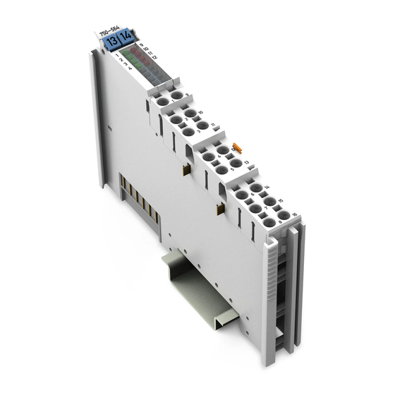
Device Description WAGO-I/O-SYSTEM 750 750-564 4AO U/I View Figure 1: View Table 4: Legend for Figure “View” Pos. Description Details See Section Marking possibility with Mini- Status LEDs “Device Description” > “Display Elements” Data contacts “Device Description” > “Connectors” ®... -
Page 19: Connectors
WAGO-I/O-SYSTEM 750 Device Description 750-564 4AO U/I Connectors 3.2.1 Data Contacts/Local Bus Communication between the head station and the I/O modules as well as the system supply of the I/O modules is carried out via the local bus. The contacting for the local bus consists of 6 data contacts, which are available as self-cleaning gold spring contacts. -
Page 20: Power Jumper Contacts/Field Supply
3.2.2 Power Jumper Contacts/Field Supply The I/O module 750-564 has 2 self-cleaning power jumper contacts that supply and transmit power for the field side. The contacts on the left side of the I/O module are designed as blade contacts and those on the right side as spring contacts. -
Page 21: Push-In Cage Clamp ® Connectors
WAGO-I/O-SYSTEM 750 Device Description 750-564 4AO U/I ® 3.2.3 Push-in CAGE CLAMP Connectors ® Figure 4: Push-in CAGE CLAMP Connectors ® Table 6: Legend for Figure “Push-in CAGE CLAMP Connectors” +AO1 Channel Designation Connector Function −AO1 Positive voltage/current output Negative voltage/current output −S1... -
Page 22: Display Elements
Device Description WAGO-I/O-SYSTEM 750 750-564 4AO U/I Display Elements Figure 5: Display Elements Table 7: Legend for Figure “Display Elements” Channel Designation LED Color Description Status signal for channel 1: Status LED 1 Green operational readiness and local bus communication... -
Page 23: Schematic Diagram
WAGO-I/O-SYSTEM 750 Device Description 750-564 4AO U/I You can find the interpretation of the internal LED states in Section “Diagnostics”. Schematic Diagram Figure 6: Schematic Diagram Manual Version 1.0.0... -
Page 24: Technical Data
Device Description WAGO-I/O-SYSTEM 750 750-564 4AO U/I Technical Data 3.5.1 Device Table 8: Technical Data – Device Width 12 mm Height (from upper edge of DIN-rail) 69 mm Depth 100 mm Weight 50 g 3.5.2 Power Supply Table 9: Technical Data – Power Supply Power supply via power jumper contact 24 VDC (−25 % …... -
Page 25: Outputs
WAGO-I/O-SYSTEM 750 Device Description 750-564 4AO U/I 3.5.4 Outputs Table 11: Technical Data – Outputs Number of outputs Output type (adjustable) • 0-10 mA • 2-10 mA • ±10 mA • 0-12 mA • ±12 mA • 0-20 mA •... -
Page 26: Climatic Environmental Conditions
Device Description WAGO-I/O-SYSTEM 750 750-564 4AO U/I Table 12: Max. Error/Temperature Drift by Output Range Max. Error at 25 °C Max. Tempe- Output Ranges [Output range end rature Drift value: %] [ppm/K] 0-10 V; 2-10 V; ±10 V; 0.05 0-5 V; 1-5 V; ±5 V 0-12 V;... -
Page 27: Approvals
[Temperature: B, Humidity: A, Vibration: B, EMC: B, Enclosure: A] More information about approvals. Detailed references to the approvals are listed in the document “Overview Approvals WAGO I/O SYSTEM 750”, which you can find via the internet under: www.wago.com DOWNLOADS Documentation System Description. Manual... -
Page 28: Standards And Guidelines
Device Description WAGO-I/O-SYSTEM 750 750-564 4AO U/I Standards and Guidelines 750-564 I/O modules meet the following standards and guidelines: ATEX Directive 2014/34/EU Explosive atmospheres. Equipment. EN 60079-0 General requirements Explosive atmospheres EN 60079-7 Equipment protection by increased safety "e" IECEx Scheme... -
Page 29: Process Image
Process Image 750-564 4AO U/I Process Image The 750-564 I/O Module provides one control/status byte (8 bits) and one data word (16 bits) per channel. The I/O module outputs signals with a 16-bit process value resolution. The digitized process value is output in a data word via the process image of the head station as output byte “0”... -
Page 30: Table 15: Process Image ("Standard") - 750-564 I/O Module
Process Image WAGO-I/O-SYSTEM 750 750-564 4AO U/I Table 15: Process Image (“Standard”) – 750-564 I/O Module Process image Output Byte 0 Process value CH1_D0 Byte 1 Process value CH1_D1 Byte 2 Process value CH2_D0 Byte 3 Process value CH2_D1 Byte 4... -
Page 31: Control And Status Bytes
WAGO-I/O-SYSTEM 750 Process Image 750-564 4AO U/I Control and Status Bytes Control and status bytes are implemented identically for all channels. Therefore, the following description in this section applies to all control and status bytes of the I/O module. Table 17: Control Byte CH1_C0... -
Page 32: Table 18: Status Byte Ch1_S0
Process Image WAGO-I/O-SYSTEM 750 750-564 4AO U/I Table 18: Status Byte CH1_S0 Status Byte CH1_S0, Byte 0 Bit 7 Bit 6 Bit 5 Bit 4 Bit 3 Bit 2 Bit 1 Bit 0 RegCom General Power Wire Short Wiring Wiring... -
Page 33: Prozess Data
WAGO-I/O-SYSTEM 750 Process Image 750-564 4AO U/I Prozess Data 4.3.1 Overview of Signal Types The following table serves as an overview of all supported signal types. With positive signals, the resolution can be set to either 16 bits or 15 bits. -
Page 34: Prozess Value (Voltage)
Process Image WAGO-I/O-SYSTEM 750 750-564 4AO U/I 4.3.2 Prozess Value (Voltage) Table 20: 0–5 V (16-Bit Resolution) Voltage Value (U) Process Value (hex) Process Value (dec) 0x0000 0x3333 13107 0x6666 26214 0x9999 39321 0xCCCC 52428 0xFFFF 65535 Table 21: 0–5 V (15-Bit Resolution) -
Page 35: Table 25: 0-10 V (16-Bit Resolution)
WAGO-I/O-SYSTEM 750 Process Image 750-564 4AO U/I Table 24: ±5 V Voltage Value (U) Process Value (hex) Process Value (dec) −5 V 0x8000 −32768 −4 V 0x999A −26214 −3 V 0xB333 −19661 −2 V 0xCCCD −13107 −1 V 0xE666 −6554... -
Page 36: Table 27: 2-10 V (16-Bit Resolution)
Process Image WAGO-I/O-SYSTEM 750 750-564 4AO U/I Table 27: 2-10 V (16-Bit Resolution) Voltage Value (U) Process Value (hex) Process Value (dec) 0x0000 0x2000 8192 0x4000 16384 0x6000 24576 0x8000 32768 0x9FFF 40959 0xBFFF 49151 0xDFFF 57343 10 V 0xFFFF... -
Page 37: Table 30: 0-12 V (16-Bit Resolution)
WAGO-I/O-SYSTEM 750 Process Image 750-564 4AO U/I Table 29: ±10 V Voltage Value (U) Process Value (hex) Process Value (dec) −10 V 0x8000 −32768 −9 V 0x8CCD −29491 −8 V 0x999A −26214 −7 V 0xA666 −22938 −6 V 0xB333 −19661 −5 V... -
Page 38: Table 31: 0-12 V (15-Bit Resolution)
Process Image WAGO-I/O-SYSTEM 750 750-564 4AO U/I Table 31: 0-12 V (15-Bit Resolution) Voltage Value (U) Process Value (hex) Process Value (dec) 0x0000 0x0AAB 2731 0x1555 5461 0x2000 8192 0x2AAA 10922 0x3555 13653 0x4000 16384 0x4AAA 19114 0x5555 21845 0x5FFF... -
Page 39: Process Values (Current)
WAGO-I/O-SYSTEM 750 Process Image 750-564 4AO U/I 4.3.3 Process Values (Current) Table 33: 0-10 mA (16-Bit Resolution) Current Value (I) Process Value (hex) Process Value (dec) 0 mA 0x0000 1 mA 0x199A 6554 2 mA 0x3333 13107 3 mA 0x4CCD... -
Page 40: Table 36: 2-10 Ma (15-Bit Resolution)
Process Image WAGO-I/O-SYSTEM 750 750-564 4AO U/I Table 36: 2-10 mA (15-Bit Resolution) Current Value (I) Process Value (hex) Process Value (dec) 2 mA 0x0000 3 mA 0x1000 4096 4 mA 0x2000 8192 5 mA 0x3000 12288 6 mA 0x4000... -
Page 41: Table 38: 0-20 Ma (16-Bit Resolution)
WAGO-I/O-SYSTEM 750 Process Image 750-564 4AO U/I Table 38: 0-20 mA (16-Bit Resolution) Current Value (I) Process Value (hex) Process Value (dec) 0 mA 0x0000 1 mA 0x0CCD 3277 2 mA 0x199A 6554 3 mA 0x2666 9830 4 mA 0x3333... -
Page 42: Table 39: 0-20 Ma (15-Bit Resolution)
Process Image WAGO-I/O-SYSTEM 750 750-564 4AO U/I Table 39: 0-20 mA (15-Bit Resolution) Current Value (I) Process Value (hex) Process Value (dec) 0 mA 0x0000 1 mA 0x0666 1638 2 mA 0x0CCD 3277 3 mA 0x1333 4915 4 mA 0x1999... -
Page 43: Table 41: 4-20 Ma (15-Bit Resolution)
WAGO-I/O-SYSTEM 750 Process Image 750-564 4AO U/I Table 41: 4-20 mA (15-Bit Resolution) Current Value (I) Process Value (hex) Process Value (dec) 4 mA 0x0000 5 mA 0x0800 2048 6 mA 0x1000 4096 7 mA 0x1800 6144 8 mA 0x2000... -
Page 44: Table 42: ±20 Ma
Process Image WAGO-I/O-SYSTEM 750 750-564 4AO U/I Table 42: ±20 mA Current Value (I) Process Value (hex) Process Value (dec) −20 mA 0x8000 −32768 −19 mA 0x8666 −31130 −18 mA 0x8CCD −29491 −17 mA 0x9333 −27853 −16 mA 0x999A −26214 −15 mA... -
Page 45: Table 43: 0-22 Ma (16-Bit Resolution)
WAGO-I/O-SYSTEM 750 Process Image 750-564 4AO U/I Table 43: 0-22 mA (16-Bit Resolution) Current Value (I) Process Value (hex) Process Value (dec) 0 mA 0x0000 1 mA 0x0BA3 2979 2 mA 0x1746 5958 3 mA 0x22E9 8937 4 mA 0x2E8B... -
Page 46: Table 44: 0-22 Ma (15-Bit Resolution)
Process Image WAGO-I/O-SYSTEM 750 750-564 4AO U/I Table 44: 0-22 mA (15-Bit Resolution) Current Value (I) Process Value (hex) Process Value (dec) 0 mA 0x0000 1 mA 0x05D1 1489 2 mA 0x0BA3 2979 3 mA 0x1174 4468 4 mA 0x1746... -
Page 47: Table 45: ±20 Ma
WAGO-I/O-SYSTEM 750 Process Image 750-564 4AO U/I Table 45: ±20 mA Current Value (I) Process Value (hex) Process Value (dec) −22 mA 0x8000 −32768 −21 mA 0x85D1 −31279 −20 mA 0x8BA3 −29789 −19 mA 0x9174 −28300 −18 mA 0x9746 −26810 −17 mA... -
Page 48: Table 46: 0-12 Ma (16-Bit Resolution)
Process Image WAGO-I/O-SYSTEM 750 750-564 4AO U/I Table 45: ±20 mA Current Value (I) Process Value (hex) Process Value (dec) +20 mA 0x745C 29788 +21 mA 0x7A2E 31278 +22 mA 0x7FFF 32767 Table 46: 0-12 mA (16-Bit Resolution) Current Value (I) -
Page 49: Table 48: ±12 Ma
WAGO-I/O-SYSTEM 750 Process Image 750-564 4AO U/I Table 48: ±12 mA Current Value (I) Process Value (hex) Process Value (dec) −12 mA 0x8000 −32768 −11 mA 0x8AAB −30037 −10 mA 0x9555 −27307 −9 mA 0xA000 −24576 −8 mA 0xAAAB −21845 −7 mA... -
Page 50: Mounting
Mounting WAGO-I/O-SYSTEM 750 750-564 4AO U/I Mounting Do not work when devices are energized! High voltage can cause electric shock or burns. Switch off all power to the device prior to performing any installation, repair or maintenance work. Risk of injury due to sharp-edged blade contacts! The blade contacts are sharp-edged. -
Page 51: Mounting Sequence
Always plug a bus end module (750-600) onto the end of the fieldbus node! You must always use a bus end module at all fieldbus nodes with WAGO I/O SYSTEM 750 fieldbus couplers or controllers to guarantee proper data transfer. -
Page 52: Inserting And Removing Devices
Mounting WAGO-I/O-SYSTEM 750 750-564 4AO U/I Inserting and Removing Devices 5.2.1 Inserting the I/O Module Position the I/O module in such a way that the groove and spring are connected to the preceding and following components. Figure 7: Inserting I/O Module (Example) Press the I/O module into the assembly until the I/O module snaps into the carrier rail. -
Page 53: Removing The I/O Module
WAGO-I/O-SYSTEM 750 Mounting 750-564 4AO U/I Once the I/O module has snapped into place, the electrical connections for the data contacts and power contacts (if any) to the head station or to the preceding and, if applicable, following I/O module are established. -
Page 54: Connect Devices
Do not connect more than one conductor at one single connection! If more than one conductor must be routed to one connection, these must be connected in an up-circuit wiring assembly, for example using WAGO feed- through terminals. Terminate both solid and stranded or ferruled conductors by simply pushing them ®... -
Page 55: Figure 10: Connecting A Conductor To A Push-In Cage Clamp
WAGO-I/O-SYSTEM 750 Connect Devices 750-564 4AO U/I ® Figure 10: Connecting a Conductor to a Push-in CAGE CLAMP Manual Version 1.0.0... -
Page 56: Connection Examples
Connect Devices WAGO-I/O-SYSTEM 750 750-564 4AO U/I Connection Examples Use shielded signal lines! Only use shielded signal lines for analog signals and I/O modules which are equipped with shield clamps. Only then can you ensure that the accuracy and interference immunity specified for the respective I/O module can be achieved even in the presence of interference acting on the signal cable. -
Page 57: Figure 12: Connection Example - 4-Conductor Connection With Sense Lines
WAGO-I/O-SYSTEM 750 Connect Devices 750-564 4AO U/I Figure 12: Connection Example – 4-Conductor Connection with Sense Lines (Voltage Output Only) Manual Version 1.0.0... -
Page 58: Commissioning
Commissioning WAGO-I/O-SYSTEM 750 750-564 4AO U/I Commissioning • Read out module information • Enable/disable output channels separately • Connect actuators • Configure/parameterize output channels • Calibrate output channels (see also Section “Calibrating Measured Values” and Section “Service” > “Recalibration”) •... -
Page 59: Configuration And Parameterization With Wago-I/O-Check
Calibration of channels and adjustment of analog outputs • Monitoring WAGO-I/O-CHECK You can obtain the WAGO-I/O-CHECK software on a CD under Item No. 759-302. This CD contains all the application program files and an explanation. You can find a description on the website at www.wago.com... -
Page 60: Control Mode
Commissioning WAGO-I/O-SYSTEM 750 750-564 4AO U/I Figure 13: WAGO-I/O-CHECK User Interface (Example) 7.1.1 Control Mode In “Control Mode,” the process output data of the individual channels can be set via write rules (assuming the fieldbus or a PFC application is not active). -
Page 61: Figure 15: "Control Mode" Menu Item
WAGO-I/O-SYSTEM 750 Commissioning 750-564 4AO U/I Figure 15: “Control Mode” Menu Item The current status of the indicator is now displayed. Click the [Process Data] menu item. Figure 16: “Process Data” Menu Item The dialog for controlling the process output data opens. -
Page 62: Parameterization Dialog
750-564 4AO U/I 7.1.2 Parameterization Dialog To open specific parameterization dialogs for the I/O Module 750-564, proceed as follows: Leave control mode by clicking the [Control-Mode] menu item again. The current status of the indicator is no longer displayed, and the [Settings] menu item can now be enabled. -
Page 63: Title Bar
The window title provides information about the position of the selected I/O module within the fieldbus node used and the item number of the selected I/O module. 7.1.2.2 Information Bar • Item number: 750-564 • Item description: 4AO U/I • Version: 01.01.xx (xx) 7.1.2.3 Buttons... -
Page 64: Menu
Commissioning WAGO-I/O-SYSTEM 750 750-564 4AO U/I 7.1.2.4 Menu Via the menu items, select the application area view. 7.1.3 Settings via the Menu 7.1.3.1 Common Figure 19: “Common” Menu Item The [Common] menu item contains the global parameters of the I/O module that are valid for all channels. -
Page 65: Table 51: "Common" Menu Item
WAGO-I/O-SYSTEM 750 Commissioning 750-564 4AO U/I Table 51: “Common” Menu Item Parameter Value Description If synchronous conversion is switched on, the output channels are processed, not one after another, but rather synchronously. Thus a change to all output stages of the Synchronous DA I/O module occurs at the same time. -
Page 66: Channel Settings
Commissioning WAGO-I/O-SYSTEM 750 750-564 4AO U/I Table 51: “Common” Menu Item Parameter Value Description If the I/O module watchdog is triggered [16-bit decimal (e.g., in the event of a faulty local bus value] connection), the outputs of the individual channels switch to a defined output state K-Bus timeout (see section “Channel Settings”). -
Page 67: Figure 21: Marking Modified Parameters
WAGO-I/O-SYSTEM 750 Commissioning 750-564 4AO U/I Figure 21: Marking Modified Parameters Table 52: Menu Items “Channel 1” ... “Channel 4” Parameter Value Description Channel deactivated, Selection of the signal type (value ranges 0-5 V, [V] or [mA]) for the channel. The channel 1-5 V, can also be deactivated in this parameter. - Page 68 Commissioning WAGO-I/O-SYSTEM 750 750-564 4AO U/I Table 52: Menu Items “Channel 1” ... “Channel 4” Parameter Value Description With resolution “15 Bit,” 15 bits are provided for the output range. Example: With a measurement range setting of “0–10 V,” 15 Bit 0x0000 = 0 V and 0x7FFF = 10 V.
-
Page 69: Scaling
WAGO-I/O-SYSTEM 750 Commissioning 750-564 4AO U/I Table 52: Menu Items “Channel 1” ... “Channel 4” Parameter Value Description Behavior when the local bus watchdog is triggered (“Local bus communication faulty”): No response from the channel. The output stage retains its last output value setting. -
Page 70: Figure 22: "Scaling" Menu Item
Commissioning WAGO-I/O-SYSTEM 750 750-564 4AO U/I Enabling user scaling allows gain and offset values to be adjusted. Checking/unchecking the box has an immediate effect! When the box is checked, the setting is written immediately to the I/O module; it is not necessary to click the [Write] button. -
Page 71: Calibration
WAGO-I/O-SYSTEM 750 Commissioning 750-564 4AO U/I Table 53: “Scaling” Menu Item for Each Channel Parameter Value Description Manufacturer scaling is active. The gain and offset values are factory-set. Manufacturer scaling deactivated. Manufacturer Offset Indicates the offset value setting. -
Page 72: Figure 23: "Calibration" Menu Item
Commissioning WAGO-I/O-SYSTEM 750 750-564 4AO U/I Checking/unchecking the box has an immediate effect! When the box is checked, the setting is written immediately to the I/O module; it is not necessary to click the [Write] button. Click the [Save] button to save your settings. The calibration process is performed on a channel basis;... -
Page 73: Configuration And Parameterization With E!Cockpit
Show values in hexadecimal Hexadecimal representation is disabled. Factory setting Configuration and Parameterization with e!COCKPIT The 750-564 I/O module is supported by the e!COCKPIT commissioning tool starting with version 1.6.1.4 – see manual “2759-0101 e!COCKPIT,” Section “Operating.” Manual Version 1.0.0... -
Page 74: Configuration And Parameterization Via Gsd File
After restart, the I/O module is re-parameterized via PROFIBUS using the GSD settings. Pos: 90 /Serie 750 (WAGO-I/O-SYSTEM)/Anhang/Konfigurieren und Parametrieren per GSD bei PROFIBUS DP und PROFINET IO 750-0652 @ 15\mod_1366809580641_6.docx @ 117978 @ 3443444 @ 1 7.3.1 4AO U/I Configuration 7.3.1.1... -
Page 75: Figure 24: Example "Device-Specific Parameters" Dialog With Profibus Dp
GSD Entry PA length Data type Inst. [Byte] Submodule Module 750-564 4AO, U/I 4AO, UINT16[4] O, 16 bit UINT16 4AO, UINT16[4] O, 16 bit, PE 4AO, INT16[4] O, 15 bit INT16 4AO, INT16[4] O, 15 bit, PE 4AO, {UINT8, UINT16}[4] I/O,... -
Page 76: Figure 25: Example "General Module/Channel Parameters" Dialog With
Commissioning WAGO-I/O-SYSTEM 750 750-564 4AO U/I Figure 25: Example “General Module/Channel Parameters” Dialog with PROFINET IO Figure 26: Example “Specific Module/Channel Parameters” Dialog with PROFINET IO Manual Version 1.0.0... -
Page 77: Figure 27: Example Of Optional "Profienergy Parameters" Dialog With
All PROFIBUS DP and PROFINET IO Fieldbus Couplers The following assignment applies to the parameters of the I/O module in connection with the use of WAGO-I/O-CHECK as well when using PROFIBUS DP and PROFINET IO fieldbus devices. Table 57: Device-Specific Parameters and Specific Module/Channel Parameters... -
Page 78: Table 58: General Module/Channel Parameters
Commissioning WAGO-I/O-SYSTEM 750 750-564 4AO U/I 7.3.2.4 PROFIBUS DP Fieldbus Couplers 750-333(/0xx-000), 750-833(/0xx-000) The PROFIBUS fieldbus couplers also allow diagnostics to be enabled on a channel basis and substitute values to be set if the setting “Substitute values are switched” was selected for the “Response to PROFIBUS DP failure” on the station representative. -
Page 79: Table 61: Profienergy Parameters
0x8000 … 0x0000 32767 … 0x7FFF Factory setting 16-bit resolution 15-bit resolution The resolution of 1/16384 is already taken into account in WAGO-I/O-CHECK. === Ende der Liste für Textmarke Inhalt_mitte === Table 61: PROFIenergy Parameters – PROFINET IO Couplers GSD File WAGO-I/O-CHECK... -
Page 80: Scaling Measured Values
Scaling Measured Values WAGO-I/O-SYSTEM 750 750-564 4AO U/I Scaling Measured Values User scaling allows you to scale the process value on an application-specific basis within the following voltage and current ranges by parameterizing the gain and offset values: • Signal type “0–10 mA”: 0 mA ... 20 mA •... -
Page 81: Calibrating Measured Values
9.1.1 Example of Determining Gain and Offset A two-point calibration method is used. Perform the following steps in WAGO-I/O-CHECK: Select a channel, as well as a signal type and the resolution, under Channel Settings. In this example, signal type “0 … 10 V” (16-bit resolution) has been selected. - Page 82 = y1 – (m × x1) b = 1 V − (0.99 × 0.97 V) = 0.04 V Enter the calculated gain value (“0.99”) in WAGO-I/O-CHECK. Convert the result for the calibration offset based on the process value resolution: 0.04 V / 0.000152579 V per digit = 262 digits...
-
Page 83: Diagnostics
WAGO-I/O-SYSTEM 750 Diagnostics 750-564 4AO U/I Diagnostics 10.1 Error States and Possible Causes Table 64: Error States in Current Output Mode Diagnostics (Status Byte) Possible Cause Wiring Error External voltage or short circuit on the analog (0x42 hex.) output in question (+AOx/−AOx) or sense input (+Sx/−Sx) -
Page 84: Table 67: Signal Evaluation For Each Channel - Error Led
Diagnostics WAGO-I/O-SYSTEM 750 750-564 4AO U/I Table 67: Signal Evaluation for Each Channel – Error LED Error LED state Possible interpretation No error Channel deactivated Diagnostics deactivated Wire break Short circuit Wiring error AO− wiring error Faulty field voltage supply... -
Page 85: Use In Hazardous Environments
Use in Hazardous Environments 750-564 4AO U/I Use in Hazardous Environments The WAGO I/O SYSTEM 750 (electrical equipment) is designed for use in Zone 2 hazardous areas and shall be used in accordance with the marking and installation regulations. The following sections include both the general identification of components (devices) and the installation regulations to be observed. -
Page 86: Marking Configuration Examples
Use in Hazardous Environments WAGO-I/O-SYSTEM 750 750-564 4AO U/I 11.1 Marking Configuration Examples 11.1.1 Marking for Europe According to ATEX and IECEx Figure 28: Marking Example per ATEX and IECEx Figure 29: Text Detail – Marking Example per ATEX and IECEx Manual Version 1.0.0... -
Page 87: Table 68: Description Of The Marking Example Per Atex And Iecex
WAGO-I/O-SYSTEM 750 Use in Hazardous Environments 750-564 4AO U/I Table 68: Description of the Marking Example per ATEX and IECEx Marking Text Description TUEV 07 ATEX 554086 X Approving authority or certificate numbers IECEx TUN 09.0001 X Dust Device group: All except mining... -
Page 88: Figure 30: Marking Example Of An Approved I/O Module Ex I Per Atex And
Use in Hazardous Environments WAGO-I/O-SYSTEM 750 750-564 4AO U/I Figure 30: Marking Example of an Approved I/O Module Ex i per ATEX and IECEx Figure 31: Text Detail – Marking Example of an Approved I/O Module Ex i per ATEX and IECEx Manual Version 1.0.0... -
Page 89: Table 69: Description Of The Marking Example Of An Approved I/O Module Ex I Per Atex And Iecex
WAGO-I/O-SYSTEM 750 Use in Hazardous Environments 750-564 4AO U/I Table 69: Description of the Marking Example of an Approved I/O Module Ex i per ATEX and IECEx Marking Text Description TUEV 12 ATEX 106032 X Approving authority or IECEx TUN 12 0039 X... -
Page 90: Marking For The United States Of America (Nec) And Canada (Cec)
Use in Hazardous Environments WAGO-I/O-SYSTEM 750 750-564 4AO U/I 11.1.2 Marking for the United States of America (NEC) and Canada (CEC) Figure 32: Marking Example According to NEC Figure 33: Text Detail – Marking Example According to NEC 500 Table 70: Description of Marking Example According to NEC 500... -
Page 91: Figure 34: Text Detail - Marking Example For Approved Ex I I/O Module
WAGO-I/O-SYSTEM 750 Use in Hazardous Environments 750-564 4AO U/I Figure 34: Text Detail – Marking Example for Approved Ex i I/O Module According to NEC 505 Table 71: Description of Marking Example for Approved Ex i I/O Module According to NEC 505... -
Page 92: Figure 36: Text Detail - Marking Example For Approved Ex I I/O Modules
Use in Hazardous Environments WAGO-I/O-SYSTEM 750 750-564 4AO U/I Figure 36: Text Detail – Marking Example for Approved Ex i I/O Modules According to CEC 18 attachment J Table 73: Description of Marking Example for Approved Ex i I/O Modules According to CEC 18... -
Page 93: Installation Regulations
Special Notes including Explosion Protection The following warning notices are to be posted in the immediately proximity of the WAGO I/O SYSTEM 750 (hereinafter “product”): WARNING – DO NOT REMOVE OR REPLACE FUSED WHILE ENERGIZED! WARNING – DO NOT DISCONNECT WHILE ENERGIZED! WARNING –... - Page 94 Use in Hazardous Environments WAGO-I/O-SYSTEM 750 750-564 4AO U/I Explosive atmosphere occurring simultaneously with assembly, installation or repair work must be ruled out. Among other things, these include the following activities • Insertion and removal of components • Connecting or disconnecting from fieldbus, antenna, D-Sub, ETHERNET or...
-
Page 95: Special Notes Regarding Ul Hazardous Location
WAGO-I/O-SYSTEM 750 Use in Hazardous Environments 750-564 4AO U/I 11.2.2 Special Notes Regarding UL Hazardous Location For UL Hazardous Location acc. to UL File E198726, the following additional requirements apply: • Use in Class I, Division 2, Group A, B, C, D or non-hazardous areas only •... -
Page 96: Service
Firmware Update/Downgrade You can update firmware on the Series 750 I/O Modules with the software “WAGO I/O-Update 750.” The I/O modules can be updated via the service interface or, for ETHERNET-based fieldbuses, via the fieldbus connection on the fieldbus coupler/controller. -
Page 97: Recalibration
WAGO-I/O-SYSTEM 750 Service 750-564 4AO U/I 12.2 Recalibration Calibrating the I/O module may provide the process value accuracy required by the application. It may be necessary to perform a recalibration in order to maintain the accuracy despite The operator of the equipment must aging of individual components of the line. -
Page 98: Wago Uii (Unique Item Identifier)
WAGO-I/O-SYSTEM 750 750-564 4AO U/I 12.3 WAGO UII (Unique Item Identifier) Each I/O module is provided with a unique WAGO UII (“Unique Item Identifier”). Application example: The I/O module can be permanently assigned a calibration certificate via this UII. Manual... -
Page 99: List Of Figures
Output ......................56 Figure 12: Connection Example – 4-Conductor Connection with Sense Lines (Voltage Output Only) ................. 57 Figure 13: WAGO-I/O-CHECK User Interface (Example) ........60 Figure 14: Selecting I/O Module ................60 Figure 15: “Control Mode” Menu Item ..............61 Figure 16: “Process Data”... -
Page 100: List Of Tables
Table 13: Technical Data ‒ Field Wiring .............. 26 Table 14: Technical Data – Climatic Environmental Conditions ......26 Table 15: Process Image (“Standard”) – 750-564 I/O Module ......30 Table 16: Process Image (“Advanced”) – 750-564 I/O Module ......30 Table 17: Control Byte CH1_C0 ................ - Page 101 WAGO-I/O-SYSTEM 750 List of Tables 101 750-564 4AO U/I Table 48: ±12 mA ....................49 Table 49: Settings Using Tools ................58 Table 50: Buttons ....................63 Table 51: “Common” Menu Item ................65 Table 52: Menu Items “Channel 1” ... “Channel 4” ..........67 Table 53: “Scaling”...
- Page 102 WAGO Kontakttechnik GmbH & Co. KG Postfach 2880 • D - 32385 Minden Hansastraße 27 • D - 32423 Minden Phone: +49 571 887 – 0 Fax: +49 571 887 – 844169 E-Mail: info@wago.com Internet: www.wago.com...
Need help?
Do you have a question about the 750-564 and is the answer not in the manual?
Questions and answers