
Related Manuals for WAGO 750-8212/040-010


Summary of Contents for WAGO 750-8212/040-010
- Page 1 Manual WAGO-I/O-SYSTEM 750 XTR 750-8212/040-010 PFC200 G2 2ETH M12 RS XTR Controller PFC200 G2; 2 x ETHERNET M12, RS-232/485; Extreme Version 1.0.0, valid from FW version 03.01.07(13)
- Page 2 We wish to point out that the software and hardware terms as well as the trademarks of companies used and/or mentioned in the present manual are generally protected by trademark or patent. WAGO is a registered trademark of WAGO Verwaltungsgesellschaft mbH. Manual Version 1.0.0, valid from FW version 03.01.07(13)
-
Page 3: Table Of Contents
WAGO-I/O-SYSTEM 750 XTR Table of Contents 750-8212/040-010 PFC200 G2 2ETH M12 RS XTR Table of Contents Notes about this Documentation ............15 Validity of this Documentation ..............15 Copyright....................15 Property rights..................16 Symbols ....................17 Number Notation ..................19 Font Conventions ................... - Page 4 Table of Contents WAGO-I/O-SYSTEM 750 XTR 750-8212/040-010 PFC200 G2 2ETH M12 RS XTR 3.8.5 Programming ..................51 3.8.6 Local Bus ..................51 3.8.7 ETHERNET ..................52 3.8.8 Communication Interface ..............52 3.8.9 Connection Type ................52 3.8.10 Mechanical Conditions ..............53 3.8.11...
- Page 5 Changing an IP Address Using the “CBM” Configuration Tool and a Terminal Program..............111 7.3.3 Changing an IP Address using “WAGO Ethernet Settings” .... 114 7.3.4 Temporarily Setting a Fixed IP Address .......... 116 Testing the Network Connection ............117 Changing Passwords ................
- Page 6 Table of Contents WAGO-I/O-SYSTEM 750 XTR 750-8212/040-010 PFC200 G2 2ETH M12 RS XTR 7.8.1.4.2 “Project Details” Group ............131 7.8.1.4.3 “Task n” Group(s) ..............132 7.8.1.5 “General PLC Runtime Configuration” Page ......133 7.8.1.5.1 “General PLC Runtime Configuration” Group ......133 7.8.1.6...
- Page 7 WAGO-I/O-SYSTEM 750 XTR Table of Contents 750-8212/040-010 PFC200 G2 2ETH M12 RS XTR 7.8.1.18.2 “Assign Owner of Service Interface (enabled after next controller reboot)” Group ............159 7.8.1.19 “Reboot Controller” Page ............160 7.8.1.19.1 “Reboot Controller” Group ............. 160 7.8.1.20 “Firmware Backup”...
- Page 8 Table of Contents WAGO-I/O-SYSTEM 750 XTR 750-8212/040-010 PFC200 G2 2ETH M12 RS XTR 7.8.1.35.3 “Trap Receiver n” Group(s) ............ 183 7.8.1.35.4 “Add New Trap Receiver” Group ........... 183 7.8.1.36 “Configuration of SNMP v3 Users” Page ........184 7.8.1.36.1 “Actually Configured v3 Users” Group(s) ....... 184 7.8.1.36.2...
- Page 9 WAGO-I/O-SYSTEM 750 XTR Table of Contents 750-8212/040-010 PFC200 G2 2ETH M12 RS XTR 7.8.2.4.12 “Ethernet” > “Ethernet Ports” Submenu ......... 207 7.8.2.4.13 “Ethernet Ports” > “Interface Xn” Submenu ......208 7.8.2.5 “Firewall” Menu ................209 7.8.2.5.1 “Firewall” > “General Configuration” Submenu ...... 210 7.8.2.5.2...
- Page 10 Table of Contents WAGO-I/O-SYSTEM 750 XTR 750-8212/040-010 PFC200 G2 2ETH M12 RS XTR 7.8.2.12.3 “SNMP” > “SNMP v1/v2c Trap Receiver Configuration” Submenu ................239 7.8.2.12.4 “SNMP” > “SNMP v3 Configuration” Submenu ...... 240 7.8.2.12.5 “SNMP” > “(Secure)SNMP firewalling” Submenu ....241 7.8.3...
-
Page 11: Table Of Contents
WAGO-I/O-SYSTEM 750 XTR Table of Contents 750-8212/040-010 PFC200 G2 2ETH M12 RS XTR 8.12 CODESYS Visualization ..............294 8.12.1 Limits of CODESYS Visualization ........... 296 8.12.2 Eliminating Errors in CODESYS Web Visualization ......298 8.12.3 FAQs about CODESYS Web Visualization ........299 e!RUNTIME Runtime Environment ............ - Page 12 Table of Contents WAGO-I/O-SYSTEM 750 XTR 750-8212/040-010 PFC200 G2 2ETH M12 RS XTR 10.5.4.2 Register 0x1101 – Watchdog Status .......... 326 10.5.4.3 Register 0x1102 – Watchdog Timeout ........326 10.5.4.4 Register 0x1103 – Watchdog Config .......... 327 10.5.4.5 Register 0x1104 – Watchdog Operation Mode ......328 10.5.5...
- Page 13 WAGO-I/O-SYSTEM 750 XTR Table of Contents 750-8212/040-010 PFC200 G2 2ETH M12 RS XTR Service ..................... 363 13.1 Inserting and Removing the Memory Card .......... 363 13.1.1 Inserting the Memory Card .............. 363 13.1.2 Removing the Memory Card ............364 13.2 Firmware Changes ................
- Page 14 Table of Contents WAGO-I/O-SYSTEM 750 XTR 750-8212/040-010 PFC200 G2 2ETH M12 RS XTR 17.1.5 Specialty Modules ................392 17.1.5.1 Serial Interfaces with Alternative Data Format ......392 17.1.5.2 SSI Transmitter Interface I/O Modules ........393 17.1.5.3 Distance and Angle Measurement ..........393 17.1.5.4...
-
Page 15: Notes About This Documentation
(750-8212/040-010). This documentation is only applicable from FW version 03.01.07(13). The device PFC200 G2 2ETH M12 RS XTR 750-8212/040-010 shall only be installed and operated according to the instructions in this manual and the system description for the WAGO I/O SYSTEM 750 XTR. -
Page 16: Property Rights
Notes about this Documentation WAGO-I/O-SYSTEM 750 XTR 750-8212/040-010 PFC200 G2 2ETH M12 RS XTR Property rights Third-party trademarks are used in this documentation. This section contains the trademarks used. The “®” and “TM” symbols are omitted hereinafter. ® ® •... -
Page 17: Symbols
WAGO-I/O-SYSTEM 750 XTR Notes about this Documentation 750-8212/040-010 PFC200 G2 2ETH M12 RS XTR Symbols Personal Injury! Indicates a high-risk, imminently hazardous situation which, if not avoided, will result in death or serious injury. Personal Injury Caused by Electric Current! Indicates a high-risk, imminently hazardous situation which, if not avoided, will result in death or serious injury. - Page 18 Notes about this Documentation WAGO-I/O-SYSTEM 750 XTR 750-8212/040-010 PFC200 G2 2ETH M12 RS XTR Additional Information: Refers to additional information which is not an integral part of this documentation (e.g., the Internet). Manual Version 1.0.0, valid from FW version 03.01.07(13)
-
Page 19: Number Notation
WAGO-I/O-SYSTEM 750 XTR Notes about this Documentation 750-8212/040-010 PFC200 G2 2ETH M12 RS XTR Number Notation Table 1: Number Notation Number Code Example Note Decimal Normal notation Hexadecimal 0x64 C notation Binary '100' In quotation marks, nibble separated '0110.0100' with dots (.) -
Page 20: Important Notes
2.1.1 Subject to Changes WAGO Kontakttechnik GmbH & Co. KG reserves the right to provide for any alterations or modifications. WAGO Kontakttechnik GmbH & Co. KG owns all rights arising from the granting of patents or from the legal protection of utility patents. -
Page 21: Technical Condition Of Specified Devices
These modules contain no parts that can be serviced or repaired by the user. The following actions will result in the exclusion of liability on the part of WAGO Kontakttechnik GmbH & Co. KG: •... -
Page 22: Safety Advice (Precautions)
Important Notes WAGO-I/O-SYSTEM 750 XTR 750-8212/040-010 PFC200 G2 2ETH M12 RS XTR Safety Advice (Precautions) For installing and operating purposes of the relevant device to your system the following safety precautions shall be observed: Do not work on devices while energized! All power sources to the device shall be switched off prior to performing any installation, repair or maintenance work. - Page 23 WAGO-I/O-SYSTEM 750 XTR Important Notes 750-8212/040-010 PFC200 G2 2ETH M12 RS XTR Do not touch hot surfaces! The surface of the housing can become hot during operation. If the device was operated at high ambient temperatures, allow it to cool off before touching it.
- Page 24 Important Notes WAGO-I/O-SYSTEM 750 XTR 750-8212/040-010 PFC200 G2 2ETH M12 RS XTR Avoid electrostatic discharge! The devices are equipped with electronic components that may be destroyed by electrostatic discharge when touched. Please observe the safety precautions against electrostatic discharge per DIN EN 61340-5-1/-3. When handling the devices, please ensure that environmental factors (personnel, work space and packaging) are properly grounded.
-
Page 25: Licensing Terms Of The Software Package Used
They can be accessed via the WBM page “Legal Information” > “Open Source Software.” You can obtain the source code with licensing terms of the open-source software from WAGO Kontakttechnik GmbH & Co. KG on request. Send your request to support@wago.com with the subject “Controller Board Support Package.”... - Page 26 Important Notes WAGO-I/O-SYSTEM 750 XTR 750-8212/040-010 PFC200 G2 2ETH M12 RS XTR performance of your control system. Use encryption methods to protect your data and observe the information provided by the Federal Office for Information Security – “Cloud: Risks and Security Tips”.
-
Page 27: Device Description
750-8212/040-010 PFC200 G2 2ETH M12 RS XTR Device Description The controller 750-8212/040-010 (PFC200 G2 2ETH M12 RS XTR) is an automation device that can perform control tasks of a PLC. It is suitable for mounting on a DIN rail and stands out on account of its various interfaces. - Page 28 CODESYS program to the data in the fieldbus process image and vice versa! Direct access is not possible! The fieldbus configuration can be defined with the WAGO-I/O-PRO or e!COCKPIT controller configuration, depending on the set runtime system (CODESYS 2 or e!RUNTIME).
- Page 29 </dg_ Only use recommended memory card! Use only the SD memory card available from WAGO (item No. 758-879/000- 001) as it is suitable for industrial applications subjected to environmental extremes and for use in this device. Compatibility with other commercially available storage media cannot be guaranteed.
-
Page 30: View
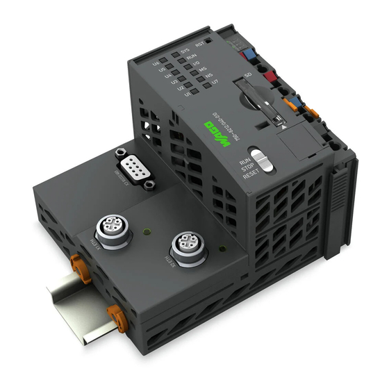
Device Description WAGO-I/O-SYSTEM 750 XTR 750-8212/040-010 PFC200 G2 2ETH M12 RS XTR View Figure 1: View Table 3: Legend for Figure “View” Item Description See section Fieldbus connection – CANopen “Connectors” > “CANopen” Marking options (Mini WSB) LED indicators – system “Display Elements”... - Page 31 WAGO-I/O-SYSTEM 750 XTR Device Description 750-8212/040-010 PFC200 G2 2ETH M12 RS XTR Table 3: Legend for Figure “View” Item Description See section LED indicator – ETHERNET “Display Elements” > connector X1 “Network Indicating Elements” ETHERNET connection X1 “Connectors” > “Network Connectors”...
-
Page 32: Labeling
Device Description WAGO-I/O-SYSTEM 750 XTR 750-8212/040-010 PFC200 G2 2ETH M12 RS XTR Labeling The front labeling includes: Device designation Name of the display elements, connections and control elements Serial number with hardware and firmware version The side labeling includes: Manufacturer's identification... -
Page 33: Connectors
WAGO-I/O-SYSTEM 750 XTR Device Description 750-8212/040-010 PFC200 G2 2ETH M12 RS XTR Connectors 3.3.1 Data Contacts/Local Bus Do not place the I/O modules on the gold spring contacts! Do not place the I/O modules on the gold spring contacts in order to avoid soiling... -
Page 34: Power Jumper Contacts/Field Supply
The blade contacts are sharp-edged. Handle the I/O module carefully to prevent injury. Do not touch the blade contacts. The controller 750-8212/040-010 is equipped with 2 self-cleaning power contacts for transferring of the field-side power supply to down-circuit I/O modules. These contacts are designed as spring contacts. -
Page 35: Cage Clamp ® Connectors
WAGO-I/O-SYSTEM 750 XTR Device Description 750-8212/040-010 PFC200 G2 2ETH M12 RS XTR ® 3.3.3 CAGE CLAMP Connectors ® Figure 5: CAGE CLAMP Connectors ® Table 5: Legend for Figure “CAGE CLAMP Connectors” Contact Designation Description 24 V System power supply voltage +24 V Field-side power supply voltage U −... -
Page 36: Service Interface
750-8212/040-010 PFC200 G2 2ETH M12 RS XTR 3.3.4 Service Interface The service interface is located behind the flap. The Service interface is used for communication with WAGO-I/O-CHECK and “WAGO Ethernet Settings”. Figure 6: Service Interface (Closed and Open Flap) Table 6: Service Interface... -
Page 37: Network Connectors
WAGO-I/O-SYSTEM 750 XTR Device Description 750-8212/040-010 PFC200 G2 2ETH M12 RS XTR 3.3.5 Network Connectors Figure 7: Network Connectors – X1, X2 Table 7: Legend for Figure “Network Connectors – X1, X2“ Signal Description TX_P Transmit Data + RX_P Receive Data + TX_N Transmit Data −... -
Page 38: Communication Interface
Device Description WAGO-I/O-SYSTEM 750 XTR 750-8212/040-010 PFC200 G2 2ETH M12 RS XTR 3.3.6 Communication Interface Figure 8: RS-232/RS-485 – Communication Connection – X3 Table 8: Legend for Figure “RS-232/RS-485 – Communication Connection – X3” RS-232 (DCE) RS-485 Contact Signal Description... -
Page 39: Operating As An Rs-232 Interface
WAGO-I/O-SYSTEM 750 XTR Device Description 750-8212/040-010 PFC200 G2 2ETH M12 RS XTR 3.3.6.1 Operating as an RS-232 Interface Kommunikationsanschluss Depending on the device type DTE (Data Terminal Equipment, e.g., PC) or DCE (Data Communication Equipment, e.g., PFC, modem), the RS-232 signals have different data directions. -
Page 40: Operating As An Rs-485 Interface
Device Description WAGO-I/O-SYSTEM 750 XTR 750-8212/040-010 PFC200 G2 2ETH M12 RS XTR 3.3.6.2 Operating as an RS-485 Interface To minimize reflection at the end of the line, the RS-485 line must be terminated at both ends by a cable termination. If required, one pull-up or pull-down resistor may be used. -
Page 41: Display Elements
WAGO-I/O-SYSTEM 750 XTR Device Description 750-8212/040-010 PFC200 G2 2ETH M12 RS XTR Display Elements 3.4.1 Power Supply Indicating Elements Figure 12: Power Supply Indicating Elements Table 10: Legend for Figure “Power Supply Indicating Elements” Description Color Description Green/off Status of system power supply voltage... -
Page 42: Fieldbus/System Indicating Elements
Device Description WAGO-I/O-SYSTEM 750 XTR 750-8212/040-010 PFC200 G2 2ETH M12 RS XTR 3.4.2 Fieldbus/System Indicating Elements Figure 13: Indicating Elements for Fieldbus/System Table 11: Legend for Figure “Fieldbus/System Indicating Elements” Designation Color Description Red/Green/ System status Orange/Off Red/Green/ PLC program status... -
Page 43: Memory Card Indicating Elements
WAGO-I/O-SYSTEM 750 XTR Device Description 750-8212/040-010 PFC200 G2 2ETH M12 RS XTR 3.4.3 Memory Card Indicating Elements Figure 14: Indicating Elements, Memory Card Slot Table 12: Legend for Figure “Indicating Elements, Memory Card Slot” Designation Color Description Yellow/Off Memory card status Manual Version 1.0.0, valid from FW version 03.01.07(13) -
Page 44: Network Indicating Elements
Device Description WAGO-I/O-SYSTEM 750 XTR 750-8212/040-010 PFC200 G2 2ETH M12 RS XTR 3.4.4 Network Indicating Elements Figure 15: LED LNK (Next to M12 Sockets) Table 13: Legend for Figure “LED LNK (Next to M12 Sockets)” Designation Color Description Green Connection exists... -
Page 45: Operating Elements
WAGO-I/O-SYSTEM 750 XTR Device Description 750-8212/040-010 PFC200 G2 2ETH M12 RS XTR Operating Elements 3.5.1 Operating Mode Switch Figure 16: Mode Selector Switch The function of the mode selector switch depends on the activated runtime system (CODESYS 2 or e!RUNTIME). -
Page 46: Reset Button
Device Description WAGO-I/O-SYSTEM 750 XTR 750-8212/040-010 PFC200 G2 2ETH M12 RS XTR 3.5.2 Reset Button Figure 17: Reset Button The Reset button is installed behind drilling to prevent operating errors. It is a shortstroke button with a low actuating force of 1.1 N … 2.1 N (110 gf … 210 gf). -
Page 47: Slot For Memory Card
</dg_ Only use recommended memory card! Use only the SD memory card available from WAGO (item No. 758-879/000- 001) as it is suitable for industrial applications subjected to environmental extremes and for use in this device. Compatibility with other commercially available storage media cannot be guaranteed. -
Page 48: Schematic Diagram
Device Description WAGO-I/O-SYSTEM 750 XTR 750-8212/040-010 PFC200 G2 2ETH M12 RS XTR Schematic Diagram Figure 19: Schematic Diagram Manual Version 1.0.0, valid from FW version 03.01.07(13) -
Page 49: Technical Data
WAGO-I/O-SYSTEM 750 XTR Device Description 750-8212/040-010 PFC200 G2 2ETH M12 RS XTR Technical Data 3.8.1 Device Data Table 16: Technical Data – Device Width 112 mm Height (from upper edge of DIN-rail) 71.9 mm Depth 100 mm Weight 214 g... -
Page 50: Supply
Device Description WAGO-I/O-SYSTEM 750 XTR 750-8212/040-010 PFC200 G2 2ETH M12 RS XTR 3.8.3 Supply Table 18: Technical Data – Supply Internal current consumption (5 VDC) 510 mA Total current for I/O modules (5 VDC) 1700 mA Input current at nominal load typ. -
Page 51: Clock
WAGO-I/O-SYSTEM 750 XTR Device Description 750-8212/040-010 PFC200 G2 2ETH M12 RS XTR 3.8.4 Clock </dg_ Table 19: Technical Data – Clock Drift - system clock (25 °C) 20 ppm Drift - RTC (25 °C) 3 ppm Buffer time RTC (25 °C) 30 days 3.8.5... -
Page 52: Ethernet
Device Description WAGO-I/O-SYSTEM 750 XTR 750-8212/040-010 PFC200 G2 2ETH M12 RS XTR 3.8.7 ETHERNET Table 22: Technical Data – ETHERNET ETHERNET 2 × M12 D-coded Transmission medium Twisted Pair S-UTP, 100 Ω, Cat 5, 100 m maximum cable length Baud rate 10/100 Mbit/s;... -
Page 53: Mechanical Conditions
WAGO-I/O-SYSTEM 750 XTR Device Description 750-8212/040-010 PFC200 G2 2ETH M12 RS XTR 3.8.10 Mechanical Conditions Table 27: Technical Data – Mechanical Conditions Vibration resistance Max. 5g Follow the installation instructions 3.8.11 Climatic Environmental Conditions Table 28: Technical Data ‒ Climatic Environmental Conditions Surrounding air temperature, operation −40 °C …... - Page 54 750-8212/040-010 PFC200 G2 2ETH M12 RS XTR More information about approvals. Detailed references to the approvals are listed in the document “Overview Approvals WAGO I/O SYSTEM 750”, which you can find via the internet under: www.wago.com DOWNLOADS Documentation System Description.
- Page 55 WAGO-I/O-SYSTEM 750 XTR Device Description 750-8212/040-010 PFC200 G2 2ETH M12 RS XTR The following ship approvals are pending for the “PFC200 G2 2ETH M12 RS XTR” controller (750-8212/040-010) described in this document: ABS (American Bureau of Shipping) LR (Lloyd’s Register) Env.
-
Page 56: Standards And Guidelines
WAGO-I/O-SYSTEM 750 XTR 750-8212/040-010 PFC200 G2 2ETH M12 RS XTR Standards and Guidelines The “PFC200 G2 2ETH M12 RS XTR” controller (750-8212/040-010) fulfills the following standards and regulations: Table 29: Standards and Rated Conditions for Explosion Protection Applications ATEX acc. Directive 2014/34/EU... -
Page 57: Table 30: Climatic And Mechanical Environmental Conditions And
WAGO-I/O-SYSTEM 750 XTR Device Description 750-8212/040-010 PFC200 G2 2ETH M12 RS XTR Table 30: Climatic and Mechanical Environmental Conditions and Shipbuilding Standard Test Value Transport EN 60870-2-2 Ct2(2k4) (except precipitation/water/moisture) Mechanical Environmental Conditions EN 61850-3 Achieved EN 60870-2-2 EN 60721-3-1... -
Page 58: Table 31: Emc - Immunity To Interference
Device Description WAGO-I/O-SYSTEM 750 XTR 750-8212/040-010 PFC200 G2 2ETH M12 RS XTR The controller 750-8212/040-010 meets the following EMC standards as these standards relate to the controller: Table 31: EMC – Immunity to Interference Standard Test Value Electrostatic Discharge • EN 61000-4-2 8 kV (contact discharge) •... - Page 59 WAGO-I/O-SYSTEM 750 XTR Device Description 750-8212/040-010 PFC200 G2 2ETH M12 RS XTR Table 31: EMC – Immunity to Interference Standard Test Value Line Frequency Disturbances • EN 60255-26 Standard not applicable Alternating Components of the Voltage to DC Line Connections •...
-
Page 60: Table 32: Emc - Emission Of Interference
Device Description WAGO-I/O-SYSTEM 750 XTR 750-8212/040-010 PFC200 G2 2ETH M12 RS XTR Table 32: EMC – Emission of Interference Standard Test Value Enclosure Emission of Interference • EN 61000-6-3 30 dB(µV/m), QP, 30 MHz … 230 MHz • EN 55032 Class B 37 dB(µV/m), QP, 230 MHz …... -
Page 61: Table 33: Standards And Rated Conditions For Rail Applications (En 50155)
5.5 EMC (Emission of Interference, EN 50121-3-2 Immunity to Interference) EN 50121-4 EN 50121-5 9.11 Materials (Fire Protection) EN 45545-2 Hazard level HL3 WAGO is a company certified in accordance with the IRIS quality standard. Manual Version 1.0.0, valid from FW version 03.01.07(13) -
Page 62: Function Description
Function Description WAGO-I/O-SYSTEM 750 XTR 750-8212/040-010 PFC200 G2 2ETH M12 RS XTR Function Description </dg_ Network 4.1.1 Interface Configuration The ETHERNET X1 and X2 interfaces of the controller are connected with an internal 3-port switch, in which the third port is connected to the CPU. -
Page 63: Network Security
WAGO-I/O-SYSTEM 750 XTR Function Description 750-8212/040-010 PFC200 G2 2ETH M12 RS XTR 4.1.2 Network Security 4.1.2.1 Users and Passwords Several groups of users are provided in the controller which can be used for various services. Default passwords are set for all users. We strongly recommend changing these... -
Page 64: Wbm User Group
Function Description WAGO-I/O-SYSTEM 750 XTR 750-8212/040-010 PFC200 G2 2ETH M12 RS XTR 4.1.2.1.2 WBM User Group WBM has its own user administration system. The users in this system are isolated from the other user groups in the system for security reasons. -
Page 65: Web Protocols For Wbm Access
WAGO-I/O-SYSTEM 750 XTR Function Description 750-8212/040-010 PFC200 G2 2ETH M12 RS XTR 4.1.2.2 Web Protocols for WBM Access The HTTP and HTTPS web protocols can be used to access the WBM pages for the controller. HTTPS is preferred because it uses the SSL/TLS protocol. The... - Page 66 Function Description WAGO-I/O-SYSTEM 750 XTR 750-8212/040-010 PFC200 G2 2ETH M12 RS XTR BSI Guidelines on Migration to TLS 1.2 The German Federal Office for Information Security guidelines on migration to TLS 1.2 contain “compatibility matrices” that show what software is comparable with TLS 1.2.
-
Page 67: Root Certificates
WAGO-I/O-SYSTEM 750 XTR Function Description 750-8212/040-010 PFC200 G2 2ETH M12 RS XTR 4.1.2.3 Root Certificates For communication encrypted with TLS, root certificates are used to verify the authenticity of the communication partner. A root certificate, which is signed by a certificate authority, serves to verify the validity of all certificates issued by this certificate authority. -
Page 68: Network Configuration
Function Description WAGO-I/O-SYSTEM 750 XTR 750-8212/040-010 PFC200 G2 2ETH M12 RS XTR </dg_ 4.1.3 Network Configuration 4.1.3.1 Host Name/Domain Name Without a host name configuration, the controller is assigned a default name which includes the last three values of the controller's MAC address, e.g., “PFCx00-A1A2A3.”... - Page 69 WAGO-I/O-SYSTEM 750 XTR Function Description 750-8212/040-010 PFC200 G2 2ETH M12 RS XTR and destination mask entries is always selected. The default gateway corresponds to the least specific routing entry. All network data packets such that no specific routing entry exists for their destination address and destination mask are sent to this default gateway.
- Page 70 Function Description WAGO-I/O-SYSTEM 750 XTR 750-8212/040-010 PFC200 G2 2ETH M12 RS XTR For forwarding network communication through a router, it is necessary to note that corresponding routing entries must be provided not only for the router, but also for the respective endpoints of the communication. The routing entries of the endpoints must ensure that the desired network data packets are sent via the router, both when the connection is established and with the replies.
-
Page 71: Network Services
WAGO-I/O-SYSTEM 750 XTR Function Description 750-8212/040-010 PFC200 G2 2ETH M12 RS XTR 4.1.5 Network Services 4.1.5.1 DHCP Client The controller can get network parameters from an external DHCP master via the DHCP Client service. The following parameters can be obtained: •... -
Page 72: Table 36: List Of Parameters Transmitted Via Dhcp
Function Description WAGO-I/O-SYSTEM 750 XTR 750-8212/040-010 PFC200 G2 2ETH M12 RS XTR The settings are made, for example, in the WBM via the “DHCP Configuration” page. The DHCP server also passes other parameters in addition to the IP address. The following table shows the complete list. -
Page 73: Dns Server
WAGO-I/O-SYSTEM 750 XTR Function Description 750-8212/040-010 PFC200 G2 2ETH M12 RS XTR server must be manually configured. For the controller, the DHCP server service is handled by the program "dnsmasq". ® From a Linux command line, an editor must be used to change the file “/etc/dnsmasq.d/dnsmasq_default.conf”... -
Page 74: Cloud Connectivity Functionality
Function Description WAGO-I/O-SYSTEM 750 XTR 750-8212/040-010 PFC200 G2 2ETH M12 RS XTR 4.1.6 Cloud Connectivity Functionality With the cloud connectivity functionality and an IEC library, the controller is available as a gateway for Internet-of-Things (IoT) applications. This means the controller can collect the data from all the connected devices, access the Internet via the built-in Ethernet interface or the mobile communications module and send the data to the cloud. -
Page 75: Components Of The Cloud Connectivity Software Package
Observe the necessary data protection and security settings! Before using the cloud connectivity functionality, consult the corresponding handbook and familiarize yourself with data protection and security issues. You will find this in the Downloads area at www.wago.com. 4.1.6.1 Components of the Cloud Connectivity Software Package... -
Page 76: Memory Card Function
Memory Card Function </dg_ Only use recommended memory card! Use only the SD memory card available from WAGO (item No. 758-879/000- 001) as it is suitable for industrial applications subjected to environmental extremes and for use in this device. Compatibility with other commercially available storage media cannot be guaranteed. - Page 77 WAGO-I/O-SYSTEM 750 XTR Function Description 750-8212/040-010 PFC200 G2 2ETH M12 RS XTR Memory card access from CODESYS only possible with FAT16, FAT32 or NTFS! If the CODESYS user “admin” (see the section “Network” > “Network Security” > “Users and Passwords” > “Services and Users“) is supposed to be able to access files created on the memory card, the memory card must be formatted with FAT16, FAT32 or NTFS.
-
Page 78: Data Backup
Function Description WAGO-I/O-SYSTEM 750 XTR 750-8212/040-010 PFC200 G2 2ETH M12 RS XTR 4.2.2 Data Backup The controller has a backup function and a restore function. The necessary settings can be made and the functions can be executed via the WBM pages or via the CBM “Backup” and “Restore” menus. -
Page 79: Restore Function
WAGO-I/O-SYSTEM 750 XTR Function Description 750-8212/040-010 PFC200 G2 2ETH M12 RS XTR The controller has an automatic update function. If this function is activated on a memory card before the data backup and a controller is booted from this memory card, this data is restored automatically on the internal memory of the controller. - Page 80 Function Description WAGO-I/O-SYSTEM 750 XTR 750-8212/040-010 PFC200 G2 2ETH M12 RS XTR File size must not exceed the size of the internal drive! Note that the amount of data in the media/sd/copy/ directory must not exceed the total size of the internal drive.
-
Page 81: Inserting A Memory Card During Operation
WAGO-I/O-SYSTEM 750 XTR Function Description 750-8212/040-010 PFC200 G2 2ETH M12 RS XTR 4.2.3 Inserting a Memory Card during Operation The fieldbus nodes and the PLC program are running. Insert a memory card during ongoing operation. During normal operation, the memory card is incorporated into the file system of the controller as a drive. -
Page 82: Setting The Home Directory For The Runtime System
Function Description WAGO-I/O-SYSTEM 750 XTR 750-8212/040-010 PFC200 G2 2ETH M12 RS XTR 4.2.5 Setting the Home Directory for the Runtime System The home directory for the runtime system is located in the controller's internal memory by default. An existing boot project may be saved in the home directory. -
Page 83: Load Boot Project
WAGO-I/O-SYSTEM 750 XTR Function Description 750-8212/040-010 PFC200 G2 2ETH M12 RS XTR 4.2.6 Load Boot Project If a boot project exists, it may be loaded, depending on the home directory setting for the runtime system. The following table shows the possible results: Table 38: Loading a Boot Project “Home... -
Page 84: Licensed Software Components
Function Description WAGO-I/O-SYSTEM 750 XTR 750-8212/040-010 PFC200 G2 2ETH M12 RS XTR Licensed Software Components The e!RUNTIME runtime system software components that are subject to license verification (runtime licenses) are available for 2nd generation controllers (750- 821x/xxx-xxx). The e!COCKPIT software can be used for licensing. You can find corresponding instructions in the documentation of e!COCKPIT. -
Page 85: Mounting
WAGO-I/O-SYSTEM 750 XTR Mounting 750-8212/040-010 PFC200 G2 2ETH M12 RS XTR Mounting Installation Position The following mounting positions are approved for the WAGO I/O SYSTEM 750 XTR: • Nominal mounting position (horizontal left) • Floor mounting position • Vertical top mounting position •... -
Page 86: Figure 21: Mounting Positions
Mounting WAGO-I/O-SYSTEM 750 XTR 750-8212/040-010 PFC200 G2 2ETH M12 RS XTR Figure 21: Mounting Positions Use an end stop in the case of vertical installation! When mounting in the “vertical top” or “vertical bottom" mounting position, also mount an end stop below the fieldbus node to protect the fieldbus node against sliding. -
Page 87: Overall Configuration
WAGO Kontakttechnik GmbH & Co. KG supplies standardized carrier rails that are optimal for use with the I/O system. If other carrier rails are used, then a technical inspection and approval of the rail by WAGO Kontakttechnik GmbH & Co. KG should take place. - Page 88 Mounting WAGO-I/O-SYSTEM 750 XTR 750-8212/040-010 PFC200 G2 2ETH M12 RS XTR • Most components have a contact to the carrier rail to ground electro- magnetic disturbances. In order to avoid corrosion, this tin-plated carrier rail contact must not form a galvanic cell with the material of the carrier rail which generates a differential voltage above 0.5 V (saline solution of 0.3 %...
-
Page 89: Wago Din Rail
WAGO-I/O-SYSTEM 750 XTR Mounting 750-8212/040-010 PFC200 G2 2ETH M12 RS XTR 5.3.2 WAGO DIN Rail WAGO carrier rails meet the electrical and mechanical requirements shown in the table below. Table 39: WAGO DIN Rail Order number Description 210-112 /-113 35 × 7.5;... -
Page 90: Spacing
Mounting WAGO-I/O-SYSTEM 750 XTR 750-8212/040-010 PFC200 G2 2ETH M12 RS XTR Spacing The spacing between adjacent components, cable conduits, casing and frame sides must be maintained for the complete fieldbus node. Figure 22: Spacing The spacing creates room for heat transfer, installation or wiring. The spacing to cable conduits also prevents conducted electromagnetic interferences from influencing the operation. -
Page 91: Mounting Sequence
Mounting 750-8212/040-010 PFC200 G2 2ETH M12 RS XTR Mounting Sequence Fieldbus couplers, controllers and I/O modules of the WAGO I/O SYSTEM 750 are snapped directly on a carrier rail in accordance with the European standard EN 60175 (DIN 35). The reliable positioning and connection is made using a tongue and groove system. -
Page 92: Inserting Devices
Mounting WAGO-I/O-SYSTEM 750 XTR 750-8212/040-010 PFC200 G2 2ETH M12 RS XTR Mixed operation Mixed operation (standard/XTR modules) within a node is possible when groups of modules are electrically isolated on the field side (i.e., electrically isolated power supply). Inserting Devices Do not work when devices are energized! High voltage can cause electric shock or burns. -
Page 93: Inserting The I/O Module
WAGO-I/O-SYSTEM 750 XTR Mounting 750-8212/040-010 PFC200 G2 2ETH M12 RS XTR 5.6.2 Inserting the I/O Module Position the I/O module so that the tongue and groove joints to the fieldbus coupler/controller or to the previous or possibly subsequent I/O module are engaged. - Page 94 Mounting WAGO-I/O-SYSTEM 750 XTR 750-8212/040-010 PFC200 G2 2ETH M12 RS XTR With the I/O module snapped in place, the electrical connections for the data contacts and power jumper contacts (if any) to the fieldbus coupler/controller or to the previous or possibly subsequent I/O module are established.
-
Page 95: Connect Devices
WAGO-I/O-SYSTEM 750 XTR Connect Devices 750-8212/040-010 PFC200 G2 2ETH M12 RS XTR Connect Devices Power Contacts/Field Supply Risk of injury due to sharp-edged blade contacts! The blade contacts are sharp-edged. Handle the I/O module carefully to prevent injury. Do not touch the blade contacts. -
Page 96: Connecting A Conductor To The Cage Clamp
Do not connect more than one conductor at one single connection! If more than one conductor must be routed to one connection, these must be connected in an up-circuit wiring assembly, for example using WAGO feed- through terminals. ®... -
Page 97: Power Supply Concept
Therefore, you should always dimension the overcurrent protection according to the anticipated power usage. The system and field voltage of the WAGO I/O SYSTEMs 750 XTR is supplied on the head stations and bus supply modules. For components that work with extra low voltage, only SELV/PELV voltage sources should be used. -
Page 98: Supplementary Power Supply Regulations
750-8212/040-010 PFC200 G2 2ETH M12 RS XTR 6.3.1 Supplementary Power Supply Regulations The WAGO-I/O-SYSTEM 750 XTR can also be used in shipbuilding applications and onshore/offshore installations (e.g., platforms, loading facilities), as well as in telecontrol applications. This is possible via certification under the standards of leading agencies such as Germanischer Lloyd and Lloyds Register. -
Page 99: Figure 28: Power Supply Concept
WAGO-I/O-SYSTEM 750 XTR Connect Devices 750-8212/040-010 PFC200 G2 2ETH M12 RS XTR Figure 28: Power Supply Concept Table 42: Legende for Figure “Power Supply Concept” Pos. Description XTR Fieldbus coupler / controller Supply filter; 24 VDC; higher isolation; extreme (750-626/040-000) XTR I/O modules Filter module for field-side power supply (surge);... -
Page 100: Supply Example
100 Connect Devices WAGO-I/O-SYSTEM 750 XTR 750-8212/040-010 PFC200 G2 2ETH M12 RS XTR 6.3.2 Supply Example SupplSggggggggggggggggg The system supply and the field supply shall be separated! You should separate the system supply and the field supply in order to ensure bus operation in the event of a short-circuit on the actuator side. -
Page 101: Table 43: Legend For Figure "Power Supply Example
WAGO-I/O-SYSTEM 750 XTR Connect Devices 101 750-8212/040-010 PFC200 G2 2ETH M12 RS XTR Table 43: Legend for Figure “Power Supply Example” Item Description Power supply on the fieldbus coupler/controller via external system supply module Supply module 24 V Supply module with bus power supply 24 V... -
Page 102: Power Supply Units
WAGO-I/O-SYSTEM 750 XTR 750-8212/040-010 PFC200 G2 2ETH M12 RS XTR 6.3.3 Power Supply Units The WAGO I/O SYSTEM 750 XTR requires 24 VDC voltage (system supply) for operation. Recommendation A stable power supply cannot always be assumed everywhere. Therefore, you should use regulated power supplies to ensure the quality of the supply voltage (see also table “WAGO power supply units”). -
Page 103: Grounding
WAGO-I/O-SYSTEM 750 XTR Connect Devices 103 750-8212/040-010 PFC200 G2 2ETH M12 RS XTR Grounding 6.4.1 Grounding the DIN Rail 6.4.1.1 Framework Assembly When setting up the framework, the carrier rail must be screwed together with the electrically conducting cabinet or housing frame. The framework or the housing must be grounded. -
Page 104: Grounding Function
104 Connect Devices WAGO-I/O-SYSTEM 750 XTR 750-8212/040-010 PFC200 G2 2ETH M12 RS XTR 6.4.2 Grounding Function The grounding function increases the resistance against electro-magnetic interferences. Some components in the I/O system have a carrier rail contact that dissipates electro-magnetic interferences to the carrier rail. -
Page 105: Shielding
Higher shielding performance is achieved via low-impedance connection between shield and ground. For this purpose, connect the shield over a large surface area, e.g., WAGO shield connecting system. This is especially recommended for large-scale systems where equalizing current or high impulse- type currents caused by atmospheric discharge may occur. -
Page 106: Shielded Signal Lines
I/O module can be achieved even in the presence of interference acting on the signal cable. On some WAGO devices you can directly clamp the shield. For all other devices use the WAGO shield connecting system. -
Page 107: Commissioning
WAGO-I/O-SYSTEM 750 XTR Commissioning 107 750-8212/040-010 PFC200 G2 2ETH M12 RS XTR Commissioning Switching On the Controller Before switching on the controller ensure that you • have properly installed the controller (see section “Installation”), • have connected all required data cables (see section “Connections”) to the... -
Page 108: Determining The Ip Address Of The Host Pc
108 Commissioning WAGO-I/O-SYSTEM 750 XTR 750-8212/040-010 PFC200 G2 2ETH M12 RS XTR Determining the IP Address of the Host PC To ensure that the host PC can communicate with the controller via ETHERNET, both devices must be located in the same subnet. -
Page 109: Setting An Ip Address
Adapt IP addressing to your specific system structure to ensure that the PC and the controller can communicate with one another using one of the available configuration tools (WBM, WAGO ETHERNET Settings or CBM – see section “Configuration”). Example for incorporating the controller (192.168.2.17) into an existing network: •... -
Page 110: Assigning An Ip Address Using Dhcp
110 Commissioning WAGO-I/O-SYSTEM 750 XTR 750-8212/040-010 PFC200 G2 2ETH M12 RS XTR 7.3.1 Assigning an IP Address using DHCP The Controller can obtain dynamic IP addresses from a server (DHCP/BootP). In contrast to fixed IP addresses, dynamically assigned addresses are not stored permanently. -
Page 111: Changing An Ip Address Using The "Cbm" Configuration Tool And A Terminal Program
WAGO-I/O-SYSTEM 750 XTR Commissioning 111 750-8212/040-010 PFC200 G2 2ETH M12 RS XTR 7.3.2 Changing an IP Address Using the “CBM” Configuration Tool and a Terminal Program You can also assign a new IP address to the ETHERNET interfaces X1 and X2 ®... -
Page 112: Figure 36: Cbm - Selecting "Networking
112 Commissioning WAGO-I/O-SYSTEM 750 XTR 750-8212/040-010 PFC200 G2 2ETH M12 RS XTR In the Main menu use the keyboard (arrow keys or numeric keypad) to move to and select Networking and then press [Enter]. Figure 36: CBM – Selecting “Networking”... -
Page 113: Figure 39: Cbm - Selecting The Ip Address
WAGO-I/O-SYSTEM 750 XTR Commissioning 113 750-8212/040-010 PFC200 G2 2ETH M12 RS XTR In the menu TCP/IP Configuration select IP Address and press [Enter]. Figure 39: CBM – Selecting the IP Address In the menu Change IP Address enter the new IP address and confirm by clicking [OK]. -
Page 114: Changing An Ip Address Using "Wago Ethernet Settings
To configure the controller use at least Version 6.4.1.1 dated 2015-06-29 of “WAGO Ethernet Settings”! You can use WAGO communication cables or WAGO radio adapters or even the IP network for data communication. Switch off the power supply to the controller. -
Page 115: Figure 42: "Wago Ethernet Settings" - "Network" Tab
“WAGO Ethernet Settings” will restart your controller. This action may require about 30 seconds.) You can now close “WAGO Ethernet Settings”, or make other changes directly in the Web-based Management system as required. To do this, click on [Run WBM] at the right in the window. -
Page 116: Temporarily Setting A Fixed Ip Address
116 Commissioning WAGO-I/O-SYSTEM 750 XTR 750-8212/040-010 PFC200 G2 2ETH M12 RS XTR </dg_ 7.3.4 Temporarily Setting a Fixed IP Address This procedure temporarily sets the IP address for the X1 interface to the fixed address “192.168.1.17”. When the switch is enabled, the fixed address is also used for interface X2. -
Page 117: Testing The Network Connection
WAGO-I/O-SYSTEM 750 XTR Commissioning 117 750-8212/040-010 PFC200 G2 2ETH M12 RS XTR Testing the Network Connection Carry out a ping network function to check whether you can reach the controller at the IP address you have assigned in the network. -
Page 118: Changing Passwords
118 Commissioning WAGO-I/O-SYSTEM 750 XTR 750-8212/040-010 PFC200 G2 2ETH M12 RS XTR Changing Passwords Change standard passwords The standard passwords are documented in these instructions and therefore do not offer adequate protection! Change the passwords to meet your particular needs! To increase security all passwords should contain a combination of lower case letters (a …... -
Page 119: Shutdown/Restart
WAGO-I/O-SYSTEM 750 XTR Commissioning 119 750-8212/040-010 PFC200 G2 2ETH M12 RS XTR </dg_ Shutdown/Restart Switch off the power supply to shut down the controller. To perform a controller restart, press the Reset button as described in the Section “Triggering Reset Functions” > “Software Reset (Restart).”... -
Page 120: Initiating Reset Functions
On a cold start reset the CODESYS 2 application is reset and the memory containing the retain variables is cleared. This corresponds to the WAGO I/O PRO IDE “Reset (Cold)” command. </dg_ To perform a cold start reset, set the mode selector switch to “Reset” and hold it there for more than seven seconds. -
Page 121: Software Reset
WAGO-I/O-SYSTEM 750 XTR Commissioning 121 750-8212/040-010 PFC200 G2 2ETH M12 RS XTR All e!RUNTIME applications are reset with a cold start reset. All global data and the retain variables are set to their initialization values. This corresponds to the e!COCKPIT IDE “Reset Cold” command. -
Page 122: Configuration
WagoConfigToolLIB.lib (section “Appendix” > “WagoConfigToolLIB.lib”) or the e!RUNTIME library “WagoAppConfigTool.lib” • Access via the PC using “WAGO Ethernet Settings” (section “Configuration Using ‘WAGO Ethernet Settings’”). The CBM is basically for the initial configuration and startup of the controller. Therefore, it only provides a subset of the WBM parameters. For example, parameters that cannot be displayed in a terminal window in a reasonable way and are not necessary for initial startup are not displayed. -
Page 123: Configuration Via Web-Based-Management (Wbm)
WAGO-I/O-SYSTEM 750 XTR Commissioning 123 750-8212/040-010 PFC200 G2 2ETH M12 RS XTR 7.8.1 Configuration via Web-Based-Management (WBM) The HTML pages (from here on referred to as “pages”) of the Web-Based Management are used to configure the controller. Proceed as follows to access... -
Page 124: Wbm User Administration
124 Commissioning WAGO-I/O-SYSTEM 750 XTR 750-8212/040-010 PFC200 G2 2ETH M12 RS XTR Some pages of the WBM are accessible only for certain users. They are only displayed if you have logged into the WBM. You can access the login form via the “Login”... -
Page 125: Figure 45: Password Reminder
WAGO-I/O-SYSTEM 750 XTR Commissioning 125 750-8212/040-010 PFC200 G2 2ETH M12 RS XTR Figure 45: Password Reminder Table 47: User Settings in the Default State Users Password user user admin wago Observe access rights Users in WBM are authorized exclusively for access to websites. User administration for controller applications is configured separately. - Page 126 126 Commissioning WAGO-I/O-SYSTEM 750 XTR 750-8212/040-010 PFC200 G2 2ETH M12 RS XTR Table 48: Access Rights for WBM Pages Navigation WBM page User – Service Interface Configuration of Service Interface admin – Reboot Reboot Controller admin Package Server – Firmware Backup...
-
Page 127: General Information About The Page
WAGO-I/O-SYSTEM 750 XTR Commissioning 127 750-8212/040-010 PFC200 G2 2ETH M12 RS XTR 7.8.1.2 General Information about the Page Figure 46: WBM Browser Window (Example) The device name is displayed in the header of the browser window. When the user has logged out, a [Login] button is displayed on the right in the header line, when logged in a [Logout] button is displayed. -
Page 128: Figure 47: Wbm Status Information (Example)
128 Commissioning WAGO-I/O-SYSTEM 750 XTR 750-8212/040-010 PFC200 G2 2ETH M12 RS XTR A status area with the following elements is displayed on the right: Figure 47: WBM Status Information (Example) • WBM status: This indicates whether the WBM is currently communicating with the device in the background. -
Page 129: Status Information" Page
WAGO-I/O-SYSTEM 750 XTR Commissioning 129 750-8212/040-010 PFC200 G2 2ETH M12 RS XTR A tooltip containing more detailed information opens as long as the cursor is positioned over an LED. The text that is displayed also contains the message that put the LED into its current status. The time of the message is also shown. -
Page 130: Table 50: Wbm "Status Information Page - "Network Details Xn" Group(S)
130 Commissioning WAGO-I/O-SYSTEM 750 XTR 750-8212/040-010 PFC200 G2 2ETH M12 RS XTR Table 50: WBM “Status Information Page – “Network Details Xn” Group(s) Parameter Explanation Status of the ETHERNET interface State (enabled/disabled) Mac Address MAC address identifies and addresses the controller... -
Page 131: Plc Runtime Information" Page
WAGO-I/O-SYSTEM 750 XTR Commissioning 131 750-8212/040-010 PFC200 G2 2ETH M12 RS XTR 7.8.1.4 “PLC Runtime Information” Page All information about the enabled runtime system and PLC program created in the programming software is provided on the “PLC Runtime Information” page. -
Page 132: Task N" Group(S)
132 Commissioning WAGO-I/O-SYSTEM 750 XTR 750-8212/040-010 PFC200 G2 2ETH M12 RS XTR 7.8.1.4.3 “Task n” Group(s) This group is only visible if CODESYS 2 is enabled as the runtime system. One dedicated group is displayed for each task when the PLC program is executed. -
Page 133: General Plc Runtime Configuration" Page
WAGO-I/O-SYSTEM 750 XTR Commissioning 133 750-8212/040-010 PFC200 G2 2ETH M12 RS XTR 7.8.1.5 “General PLC Runtime Configuration” Page The settings for the boot project created with the programming software are given on the “General PLC Runtime Configuration” page. 7.8.1.5.1 “General PLC Runtime Configuration” Group Table 54: WBM “General PLC Runtime Configuration”... - Page 134 134 Commissioning WAGO-I/O-SYSTEM 750 XTR 750-8212/040-010 PFC200 G2 2ETH M12 RS XTR Click [Submit] to apply the change. The runtime system change is effective immediately. The home directory change only takes effect after restarting the controller. For this purpose, use the WBM reboot function. Do not shut down the controller too...
-
Page 135: Plc Webvisu" Page
WAGO-I/O-SYSTEM 750 XTR Commissioning 135 750-8212/040-010 PFC200 G2 2ETH M12 RS XTR 7.8.1.6 “PLC WebVisu” Page The settings for the web visualization created in the runtime system are shown on the “PLC WebVisu” page. 7.8.1.6.1 “Web Server Configuration” Group Table 55: WBM “PLC WebVisu” Page – “Web Server Configuration” Group... -
Page 136: Configuration Of Host And Domain Name" Page
136 Commissioning WAGO-I/O-SYSTEM 750 XTR 750-8212/040-010 PFC200 G2 2ETH M12 RS XTR 7.8.1.7 “Configuration of Host and Domain Name” Page The settings for the general TCP/IP parameters are found on the “Configuration of Host and Domain Name” page. 7.8.1.7.1 “HostName” Group Table 56: WBM “Configuration of Host and Domain Name”... -
Page 137: Tcp/Ip Configuration" Page
WAGO-I/O-SYSTEM 750 XTR Commissioning 137 750-8212/040-010 PFC200 G2 2ETH M12 RS XTR </dg_ 7.8.1.8 “TCP/IP Configuration” Page The TCP/IP settings for the ETHERNET interfaces are shown on the “TCP/IP configuration” page. 7.8.1.8.1 “IP Configuration (Xn)” Group(s) If the switch is enabled, one group (“IP Configuration”) is shown for both connections. -
Page 138: Default Gateway N" Groups
138 Commissioning WAGO-I/O-SYSTEM 750 XTR 750-8212/040-010 PFC200 G2 2ETH M12 RS XTR 7.8.1.8.2 “Default Gateway n” Groups You can configure two default gateways. The controller transmits all network data not going to a station on the local network to a default gateway. First the gateway with the lowest metric is addressed. -
Page 139: Dns Server" Group
WAGO-I/O-SYSTEM 750 XTR Commissioning 139 750-8212/040-010 PFC200 G2 2ETH M12 RS XTR 7.8.1.8.3 “DNS Server” Group Table 60: WBM “TCP/IP Configuration” Page – “DNS Server” Group Parameters Explanation The addresses of the defined DNS servers are Configured: None/ displayed. If no server has been defined, DNS Server n “Configured: None”... -
Page 140: Ethernet Configuration" Page
140 Commissioning WAGO-I/O-SYSTEM 750 XTR 750-8212/040-010 PFC200 G2 2ETH M12 RS XTR 7.8.1.9 “Ethernet Configuration” Page The settings for Ethernet TCP/IP are located on the “Ethernet Configuration” page. 7.8.1.9.1 “Switch Configuration” Group Table 61: WBM “Ethernet Configuration” Page – “Switch Configuration” Group... -
Page 141: Interface Xn" Groups
WAGO-I/O-SYSTEM 750 XTR Commissioning 141 750-8212/040-010 PFC200 G2 2ETH M12 RS XTR 7.8.1.9.2 “Interface Xn” Groups One group (“Interface X1” / “Interface X2”) is displayed for each connection. Table 62: WBM “Ethernet Configuration” Page – “Interface Xn” Groups Parameter Explanation Enabled You can enable or disable the interface. -
Page 142: Routing" Page
142 Commissioning WAGO-I/O-SYSTEM 750 XTR 750-8212/040-010 PFC200 G2 2ETH M12 RS XTR 7.8.1.10 “Routing” Page On the “Routing” page you can find settings and information on the routing between the network interfaces. 7.8.1.10.1 “General Routing Configuration” Group Table 63: WBM “Routing” Page – “General Routing Configuration” Group... -
Page 143: Static Routes" Group
WAGO-I/O-SYSTEM 750 XTR Commissioning 143 750-8212/040-010 PFC200 G2 2ETH M12 RS XTR 7.8.1.10.2 “Static Routes” Group Each configured static route has its own area in the display. To maintain compatibility with earlier firmware versions, at least two routing entries always exist. These can be disabled, but not removed. If a route is either removed or disabled, it is no longer entered in the system. -
Page 144: Dynamic Routes" Group
144 Commissioning WAGO-I/O-SYSTEM 750 XTR 750-8212/040-010 PFC200 G2 2ETH M12 RS XTR 7.8.1.10.3 “Dynamic Routes” Group All default gateways received via DHCP are displayed here. Default gateways configured via DHCP are given the metric value 10, which means that they are normally used before the statically configured default gateways. -
Page 145: Port Forwarding" Group
WAGO-I/O-SYSTEM 750 XTR Commissioning 145 750-8212/040-010 PFC200 G2 2ETH M12 RS XTR 7.8.1.10.5 “Port Forwarding” Group Each entry has its own area in the display. Table 66: WBM “Routing” Page – “Port Forwarding” Group Parameter Explanation Specify here whether port forwarding should be used. -
Page 146: General Firewall Configuration" Page
146 Commissioning WAGO-I/O-SYSTEM 750 XTR 750-8212/040-010 PFC200 G2 2ETH M12 RS XTR 7.8.1.11 “General Firewall Configuration” Page 7.8.1.11.1 “Global Firewall Parameters” Group Table 67: WBM “General Firewall Configuration” Page – “Global Firewall Parameters” Group Parameters Explanation Enables/disables the complete functionality of the firewall. -
Page 147: Firewall Parameters Interface Xxx" Group
WAGO-I/O-SYSTEM 750 XTR Commissioning 147 750-8212/040-010 PFC200 G2 2ETH M12 RS XTR 7.8.1.11.2 “Firewall Parameters Interface xxx” Group These settings in this group refer to the configuration of the firewall at IP level. Table 68: WBM “General Firewall Configuration” Page – “Firewall Parameter Interface xxx” Group... -
Page 148: Configuration Of Mac Address Filter" Page
148 Commissioning WAGO-I/O-SYSTEM 750 XTR 750-8212/040-010 PFC200 G2 2ETH M12 RS XTR </dg_ 7.8.1.12 “Configuration of MAC Address Filter” Page You set the firewall configuration at ETHERNET level on this page. The “MAC Address Filter Whitelist” contains a default entry with the following... -
Page 149: Mac Address Filter State Xn" Group
WAGO-I/O-SYSTEM 750 XTR Commissioning 149 750-8212/040-010 PFC200 G2 2ETH M12 RS XTR 7.8.1.12.2 “MAC Address Filter State Xn” Group Table 70: WBM “Configuration of MAC Address Filter” Page – “MAC Address Filter State Xn” Group Parameters Explanation Enable or disable here the MAC address filter for the Filter enabled specific interface. -
Page 150: Configuration Of User Filter" Page
150 Commissioning WAGO-I/O-SYSTEM 750 XTR 750-8212/040-010 PFC200 G2 2ETH M12 RS XTR 7.8.1.13 “Configuration of User Filter” Page 7.8.1.13.1 “User Filter” Group Table 72: WBM “Configuration of User Filter” Page – “User Filter” Group Parameters Explanation Count The number of configured user filters is displayed. -
Page 151: Add New User Filter" Group
WAGO-I/O-SYSTEM 750 XTR Commissioning 151 750-8212/040-010 PFC200 G2 2ETH M12 RS XTR 7.8.1.13.3 “Add New User Filter” Group You can enter 10 filters. You only have to enter values in the fields that are to be set for the filter. At least one value must be entered, all other fields can remain empty. -
Page 152: Configuration Of Time And Date" Page
152 Commissioning WAGO-I/O-SYSTEM 750 XTR 750-8212/040-010 PFC200 G2 2ETH M12 RS XTR 7.8.1.14 “Configuration of Time and Date” Page The settings for date and time are shown on the “Configuration of Time and Date” page. 7.8.1.14.1 “Date on Device” Group Table 75: WBM “Configuration of Time and Date”... -
Page 153: Time Zone" Group
WAGO-I/O-SYSTEM 750 XTR Commissioning 153 750-8212/040-010 PFC200 G2 2ETH M12 RS XTR 7.8.1.14.3 “Time Zone” Group You can specify the appropriate time zone for your location in this group. The total number of possible time zones is over 500. A complete listing would exceed the scope of this documentation. -
Page 154: Tz String" Group
154 Commissioning WAGO-I/O-SYSTEM 750 XTR 750-8212/040-010 PFC200 G2 2ETH M12 RS XTR 7.8.1.14.4 “TZ String” Group In this group you can enter a time zone that is not contained in the “Time Zone” selection. If the controller can associate the TZ string entered with a known time zone that had been missing from the “Time Zone”... -
Page 155: Configuration Of The Users For The Web-Based Management" Page
WAGO-I/O-SYSTEM 750 XTR Commissioning 155 750-8212/040-010 PFC200 G2 2ETH M12 RS XTR </dg_ 7.8.1.15 “Configuration of the Users for the Web-based Management” Page The settings for user administration are shown on this page. 7.8.1.15.1 “Change Password for Selected User” Group... -
Page 156: Create Bootable Image" Page
156 Commissioning WAGO-I/O-SYSTEM 750 XTR 750-8212/040-010 PFC200 G2 2ETH M12 RS XTR </dg_ 7.8.1.16 “Create Bootable Image” Page You can create a bootable image on the “Create Bootable Image” page. 7.8.1.16.1 "Create Bootable Image from Active Partition (<Active Partition>" Group The active partition that boot-up was performed from is displayed in brackets in the heading. - Page 157 WAGO-I/O-SYSTEM 750 XTR Commissioning 157 750-8212/040-010 PFC200 G2 2ETH M12 RS XTR Remove the memory card write protection! Because write access to the memory card is possible during the boot process, the memory card cannot be write protected when creating the image and during operation.
-
Page 158: Configuration Of Serial Interface Rs232" Page
158 Commissioning WAGO-I/O-SYSTEM 750 XTR 750-8212/040-010 PFC200 G2 2ETH M12 RS XTR </dg_ 7.8.1.17 “Configuration of Serial Interface RS232” Page The settings for the serial interface are shown on the “Configuration of Serial Interface RS232” page. 7.8.1.17.1 “Serial Interface Assigned to” Group The application that the serial interface is currently assigned to is displayed. -
Page 159: Configuration Of Service Interface" Page
WAGO-I/O-SYSTEM 750 XTR Commissioning 159 750-8212/040-010 PFC200 G2 2ETH M12 RS XTR 7.8.1.18 “Configuration of Service Interface” Page The settings for the service interface are shown on the “Configuration of the Service Interface” page. 7.8.1.18.1 “Service Interface assigned to” Group The application that the service interface is currently assigned to is displayed. -
Page 160: Reboot Controller" Page
160 Commissioning WAGO-I/O-SYSTEM 750 XTR 750-8212/040-010 PFC200 G2 2ETH M12 RS XTR </dg_ 7.8.1.19 “Reboot Controller” Page The settings for the system reboot are shown on the “Reboot Controller” page. 7.8.1.19.1 “Reboot Controller” Group Click the [Reboot] button to reboot the system. -
Page 161: Firmware Backup" Page
WAGO-I/O-SYSTEM 750 XTR Commissioning 161 750-8212/040-010 PFC200 G2 2ETH M12 RS XTR 7.8.1.20 “Firmware Backup” Page You can find the controller data backup settings on the “Firmware Backup” page. Table 83: “Firmware-Backup” WBM Page Parameters Explanation You can select the data to be backed up here. - Page 162 162 Commissioning WAGO-I/O-SYSTEM 750 XTR 750-8212/040-010 PFC200 G2 2ETH M12 RS XTR No backup of the memory card! Backup from the memory card to the internal flash memory is not possible. Account for backup time Generation of backup files can take several minutes. Stop the CODESYS program before you start the backup procedure to help shorten the time required.
-
Page 163: Firmware Restore" Page
WAGO-I/O-SYSTEM 750 XTR Commissioning 163 750-8212/040-010 PFC200 G2 2ETH M12 RS XTR 7.8.1.21 “Firmware Restore” Page The settings for restoring the controller data are shown on the “Firmware Restore” page. Table 84: “Firmware Restore” WBM Page Parameters Explanation Select the data source for the restore here. - Page 164 164 Commissioning WAGO-I/O-SYSTEM 750 XTR 750-8212/040-010 PFC200 G2 2ETH M12 RS XTR Note the firmware version! Restoring the controller operating system (“System” selection) is only permissible and possible if the firmware versions at the backup and restore times are identical.
-
Page 165: System Partition" Page
WAGO-I/O-SYSTEM 750 XTR Commissioning 165 750-8212/040-010 PFC200 G2 2ETH M12 RS XTR </dg_ 7.8.1.22 “System Partition” Page The settings for specifying the partition that the system will be started from are shown on the “System Partition” page. 7.8.1.22.1 “Current Active Partition” Group The partition currently in use is displayed here. -
Page 166: Mass Storage" Page
166 Commissioning WAGO-I/O-SYSTEM 750 XTR 750-8212/040-010 PFC200 G2 2ETH M12 RS XTR </dg_ 7.8.1.23 “Mass Storage” Page A group containing information about the storage volume is displayed for each storage volume that is found, along with an additional group for formatting (when this is possible). -
Page 167: Software Uploads" Page
WAGO-I/O-SYSTEM 750 XTR Commissioning 167 750-8212/040-010 PFC200 G2 2ETH M12 RS XTR </dg_ 7.8.1.24 “Software Uploads” Page The settings for a device update are shown on the “Software Uploads” page. 7.8.1.24.1 “Upload New Software” Group Table 87: WBM “Software Uploads” Page – “Upload New Software” Group... -
Page 168: Configuration Of Network Services" Page
168 Commissioning WAGO-I/O-SYSTEM 750 XTR 750-8212/040-010 PFC200 G2 2ETH M12 RS XTR 7.8.1.25 “Configuration of Network Services” Page The settings for various services are shown on the “Configuration of Network Services” page. Besides enabling/disabling the individual services, you can also limit the services for each particular interface via the firewall on the “General Firewall... -
Page 169: Http" Group
WAGO-I/O-SYSTEM 750 XTR Commissioning 169 750-8212/040-010 PFC200 G2 2ETH M12 RS XTR 7.8.1.25.4 “HTTP” Group Table 92: WBM “Configuration of Network Services” Page – “HTTP” Group Parameter Explanation Service active Enable/disable the HTTP service here. Click the [Submit] button to apply the changes. The change takes effect immediately. -
Page 170: Opc Ua" Group
170 Commissioning WAGO-I/O-SYSTEM 750 XTR 750-8212/040-010 PFC200 G2 2ETH M12 RS XTR 7.8.1.25.7 “OPC UA” Group Table 95: WBM “Configuration of Network Services” Page – “OPC UA” Group Parameter Explanation Service active Enable/disable the OPC UA service here. Click the [Submit] button to apply the changes. The change only takes effect once the controller restarts. -
Page 171: Configuration Of Ntp Client" Page
WAGO-I/O-SYSTEM 750 XTR Commissioning 171 750-8212/040-010 PFC200 G2 2ETH M12 RS XTR </dg_ 7.8.1.26 “Configuration of NTP Client” Page The settings for the NTP service are shown on the “Configuration of NTP Client” page. 7.8.1.26.1 “NTP Client Configuration” Group Table 96: WBM “Configuration of NTP Client” Page – “NTP Client Configuration” Group... -
Page 172: Configuration Of Plc Runtime Services" Page
172 Commissioning WAGO-I/O-SYSTEM 750 XTR 750-8212/040-010 PFC200 G2 2ETH M12 RS XTR 7.8.1.27 “Configuration of PLC Runtime Services” Page The settings for various services of the activated runtime system are shown on the “Configuration of PLC Runtime Services” page. 7.8.1.27.1 “General Configuration” Group Table 97: WBM “Configuration of PLC Runtime Services”... -
Page 173: Ssh Server Settings" Page
WAGO-I/O-SYSTEM 750 XTR Commissioning 173 750-8212/040-010 PFC200 G2 2ETH M12 RS XTR 7.8.1.28 “SSH Server Settings” Page The settings for the SSH service are shown on the “SSH Server Settings” page. 7.8.1.28.1 “SSH Server” Group Table 100: WBM “SSH Server Settings” Page – “SSH Server” Group... -
Page 174: Dhcp Configuration" Page
174 Commissioning WAGO-I/O-SYSTEM 750 XTR 750-8212/040-010 PFC200 G2 2ETH M12 RS XTR 7.8.1.30 “DHCP Configuration” Page The settings for the DHCP service are shown on the “DHCP Configuration” page. 7.8.1.30.1 “DHCP Configuration Xn” Group Table 102: WBM “DHCP Configuration” – “DHCP Configuration Xn” Group... -
Page 175: Configuration Of Dns Service" Page
WAGO-I/O-SYSTEM 750 XTR Commissioning 175 750-8212/040-010 PFC200 G2 2ETH M12 RS XTR 7.8.1.31 “Configuration of DNS Service” Page The settings for the DNS service are shown on the “Configuration of DNS Service” page. 7.8.1.31.1 “DNS Service” Group Table 103: WBM “Configuration of DNS Service” Page – “DNS Service” Group... -
Page 176: Modbus Services Configuration" Page
176 Commissioning WAGO-I/O-SYSTEM 750 XTR 750-8212/040-010 PFC200 G2 2ETH M12 RS XTR 7.8.1.32 “Modbus Services Configuration” Page The settings for various Modbus services are shown on the “Modbus Services Configuration” page. The groups are only visible if the e!RUNTIME system is enabled. -
Page 177: Configuration Of Cloud Connectivity" Page
WAGO-I/O-SYSTEM 750 XTR Commissioning 177 750-8212/040-010 PFC200 G2 2ETH M12 RS XTR 7.8.1.33 “Configuration of Cloud Connectivity” Page On the page “Configuration of Cloud Connectivity” you can find the settings and information for cloud access. Observe the additional documentation! You can find a detailed description of the “Cloud Connectivity” software package with a controller and information on PLC programming in Application Note A500920 in the Downloads area at www.wago.com! -
Page 178: Settings" Group
178 Commissioning WAGO-I/O-SYSTEM 750 XTR 750-8212/040-010 PFC200 G2 2ETH M12 RS XTR 7.8.1.33.3 “Settings” Group The parameters indicated depend on the cloud platform setting and, if applicable, on other settings in this group. Table 108: WBM “Configuration of Cloud Connectivity” Page – “Settings” Group... - Page 179 WAGO-I/O-SYSTEM 750 XTR Commissioning 179 750-8212/040-010 PFC200 G2 2ETH M12 RS XTR Table 108: WBM “Configuration of Cloud Connectivity” Page – “Settings” Group Parameter Explanation Enter the path here to the file encoded in PEM Key file format that contains the private key for cloud service authentication.
-
Page 180: Table 109: Dependencies Of The Selection And Input Fields For The Selected Cloud Platform
180 Commissioning WAGO-I/O-SYSTEM 750 XTR 750-8212/040-010 PFC200 G2 2ETH M12 RS XTR Table 109: Dependencies of the Selection and Input Fields for the Selected Cloud Platform Data Cloud Platform Protocol Selection or Input Field Service enabled Cloud platform Host name Group ID >... -
Page 181: Configuration Of General Snmp Parameters" Page
WAGO-I/O-SYSTEM 750 XTR Commissioning 181 750-8212/040-010 PFC200 G2 2ETH M12 RS XTR 7.8.1.34 “Configuration of General SNMP Parameters” Page The general settings for SNMP are given on the “Configuration of General SNMP Parameters” page. 7.8.1.34.1 “General SNMP Configuration” Group Table 110: WBM “Configuration of General SNMP Parameters” Page – “General SNMP Configuration”... -
Page 182: Configuration Of Snmp V1/V2C Parameters" Page
182 Commissioning WAGO-I/O-SYSTEM 750 XTR 750-8212/040-010 PFC200 G2 2ETH M12 RS XTR 7.8.1.35 “Configuration of SNMP v1/v2c Parameters” Page The general settings for SNMP v1/v2c are shown on the “Configuration of SNMP v1/v2c Parameters” page. 7.8.1.35.1 “SNMP v1/v2c Manager Configuration” Group Table 111: WBM “Configuration of SNMP v1/v2c Parameters”... -
Page 183: Trap Receiver N" Group(S)
WAGO-I/O-SYSTEM 750 XTR Commissioning 183 750-8212/040-010 PFC200 G2 2ETH M12 RS XTR 7.8.1.35.3 “Trap Receiver n” Group(s) A dedicated group with the following information is displayed for each trap receiver: Table 113: WBM “Configuration of SNMP v1/v2c Parameters” Page – “Trap Receiver n” Group(s) -
Page 184: Configuration Of Snmp V3 Users" Page
184 Commissioning WAGO-I/O-SYSTEM 750 XTR 750-8212/040-010 PFC200 G2 2ETH M12 RS XTR </dg_ 7.8.1.36 “Configuration of SNMP v3 Users” Page The general settings for SNMP v3 are shown on the “Configuration of SNMP v3 Users” page. 7.8.1.36.1 “Actually Configured v3 Users” Group(s) Table 115: WBM “Configuration of SNMP v3”... -
Page 185: Add New V3 User" Group
WAGO-I/O-SYSTEM 750 XTR Commissioning 185 750-8212/040-010 PFC200 G2 2ETH M12 RS XTR 7.8.1.36.3 “Add New v3 User” Group You can enter 10 users. Table 117: WBM “Configuration of SNMP v3 Users” Page – “Add New v3 User” Group Parameters Explanation Enter the user name here. -
Page 186: Diagnostic Information" Page
186 Commissioning WAGO-I/O-SYSTEM 750 XTR 750-8212/040-010 PFC200 G2 2ETH M12 RS XTR </dg_ 7.8.1.37 “Diagnostic Information” Page The settings for displaying diagnostic messages are shown on the “Diagnostic Information” page. Table 118: WBM “Diagnostic Information” Page Parameter Explanation Read all notifications Activate display of all messages. -
Page 187: Configuration Of Openvpn And Ipsec" Page
WAGO-I/O-SYSTEM 750 XTR Commissioning 187 750-8212/040-010 PFC200 G2 2ETH M12 RS XTR 7.8.1.38 “Configuration of OpenVPN and IPsec” Page The general settings for OpenVPN and IPsec are shown on the “Configuration of OpenVPN and IPsec” page. 7.8.1.38.1 “OpenVPN” Group Table 119: WBM “Configuration of OpenVPN and IPsec” Page – “OpenVPN” Group... -
Page 188: Certificate Upload" Group
188 Commissioning WAGO-I/O-SYSTEM 750 XTR 750-8212/040-010 PFC200 G2 2ETH M12 RS XTR To transfer the selected file from the controller to the PC, click [Start Download] button. The changes only take effect after restarting the controller. For this purpose, use the WBM reboot function. -
Page 189: Security Settings" Page
“Open Source Licenses” page. 7.8.1.41 “WAGO Licenses” Page The licence conditions for the WAGO software used in the controller are listed on the “WAGO Licenses” page. Manual Version 1.0.0, valid from FW version 03.01.07(13) -
Page 190: Configuration Via Console-Based-Management-Tool (Cbm) Using A Terminal Program
190 Commissioning WAGO-I/O-SYSTEM 750 XTR 750-8212/040-010 PFC200 G2 2ETH M12 RS XTR 7.8.2 Configuration via Console-Based-Management-Tool (CBM) using a Terminal Program The Console-Based Management Tool (CBM) is basically used for the initial configuration and startup of the controller via a terminal program. -
Page 191: Figure 48: Cbm Main Menu (Example)
WAGO-I/O-SYSTEM 750 XTR Commissioning 191 750-8212/040-010 PFC200 G2 2ETH M12 RS XTR Start the configuration tool by entering the command “cbm” (case sensitive) on the command line and then press [Enter]. Figure 48: CBM main menu (example) Manual Version 1.0.0, valid from FW version 03.01.07(13) -
Page 192: Cbm Menu Structure Overview
192 Commissioning WAGO-I/O-SYSTEM 750 XTR 750-8212/040-010 PFC200 G2 2ETH M12 RS XTR 7.8.2.1 CBM Menu Structure Overview Table 125: CBM Menu Structure Menu Hierarchy 0. Quit 1. Information 0. Back to Main Menu 1. Controller Details 2. Network Details 2. PLC Runtime 0. - Page 193 WAGO-I/O-SYSTEM 750 XTR Commissioning 193 750-8212/040-010 PFC200 G2 2ETH M12 RS XTR Table 125: CBM Menu Structure Menu Hierarchy 1. Users 2. Create Image 3. Owner of Serial Interface 4. Reboot Controller 7. Package Server 0. Back to Main Menu 1.
-
Page 194: Information" Menu
194 Commissioning WAGO-I/O-SYSTEM 750 XTR 750-8212/040-010 PFC200 G2 2ETH M12 RS XTR Do not power cycle the controller after changing any parameters! Some parameter changes require a controller restart for the changes to apply. Saving changes takes time. Do not power cycle the controller to perform a restart, i.e., changes may be lost by shutting down the controller too soon. -
Page 195: Information" > "Network Details" Submenu
WAGO-I/O-SYSTEM 750 XTR Commissioning 195 750-8212/040-010 PFC200 G2 2ETH M12 RS XTR 7.8.2.2.2 “Information” > “Network Details” Submenu In this submenu, the network and interface properties of the controller are displayed. If the EHERNET interfaces are operated in “Switched” mode, a common table (“X1/X2”) is displayed for both connections. -
Page 196: Plc Runtime" Menu
196 Commissioning WAGO-I/O-SYSTEM 750 XTR 750-8212/040-010 PFC200 G2 2ETH M12 RS XTR 7.8.2.3 “PLC Runtime” Menu This menu contains other submenus with information and settings for the runtime system. Table 129: “PLC Runtime” Menu Menu Item Explanation 0. Back to …... -
Page 197: Information" > "Runtime Version" Submenu
WAGO-I/O-SYSTEM 750 XTR Commissioning 197 750-8212/040-010 PFC200 G2 2ETH M12 RS XTR 7.8.2.3.2 “Information” > “Runtime Version” Submenu In this submenu, the runtime version is displayed. Table 131: “PLC Runtime” > “Information” > “Runtime Version” Submenu Parameters Explanation The version of the currently enabled runtime system Version is shown. -
Page 198: Information" > "Number Of Tasks" Submenu
198 Commissioning WAGO-I/O-SYSTEM 750 XTR 750-8212/040-010 PFC200 G2 2ETH M12 RS XTR 7.8.2.3.5 “Information” > “Number of Tasks” Submenu In this submenu, the number of tasks in the PLC program are displayed. The submenu only appears when CODESYS 2 is enabled as the runtime system. -
Page 199: Tasks" > "Task N" Submenu
WAGO-I/O-SYSTEM 750 XTR Commissioning 199 750-8212/040-010 PFC200 G2 2ETH M12 RS XTR 7.8.2.3.8 “Tasks” > “Task n” Submenu In this submenu, information on the selected task is displayed. The submenu only appears when CODESYS 2 is enabled as the runtime system. -
Page 200: General Configuration" > "Plc Runtime Version" Submenu
200 Commissioning WAGO-I/O-SYSTEM 750 XTR 750-8212/040-010 PFC200 G2 2ETH M12 RS XTR 7.8.2.3.10 “General Configuration” > “PLC Runtime Version” Submenu In this submenu, select which PLC runtime system is enabled. Table 139: “PLC Runtime” > “General Configuration” > “PLC Runtime Version” Submenu... -
Page 201: Plc Runtime" > "Webvisu" Submenu
WAGO-I/O-SYSTEM 750 XTR Commissioning 201 750-8212/040-010 PFC200 G2 2ETH M12 RS XTR 7.8.2.3.12 “PLC Runtime” > “WebVisu” Submenu This submenu contains information and settings for the Web visualization. Table 141: “PLC Runtime” > “WebVisu” Submenu Menu Item Submenu Item / Explanation 0. -
Page 202: Networking" Menu
202 Commissioning WAGO-I/O-SYSTEM 750 XTR 750-8212/040-010 PFC200 G2 2ETH M12 RS XTR 7.8.2.4 “Networking” Menu This menu contains other submenus with settings for the network configuration. Table 142: “Networking” Menu Parameters Explanation 0. Back to … Back to the higher-level menu Opens a submenu with setting options for the 1. -
Page 203: Host/Domain Name" > "Hostname" Submenu
WAGO-I/O-SYSTEM 750 XTR Commissioning 203 750-8212/040-010 PFC200 G2 2ETH M12 RS XTR 7.8.2.4.2 “Host/Domain Name” > “Hostname” Submenu In this submenu, you can set the hostname of the controller. Table 144: “Networking” > “Hostname” Submenu Parameters Explanation Enter here the hostname of the controller to be used... -
Page 204: Tcp/Ip" > "Ip Address" Submenu
204 Commissioning WAGO-I/O-SYSTEM 750 XTR 750-8212/040-010 PFC200 G2 2ETH M12 RS XTR 7.8.2.4.5 “TCP/IP” > “IP Address” Submenu This submenu contains other submenus with settings for the ETHERNET interfaces. The submenu only appears if the controller is operated in “Separated” mode. -
Page 205: Tcp/Ip" > "Default Gateway" Submenu
WAGO-I/O-SYSTEM 750 XTR Commissioning 205 750-8212/040-010 PFC200 G2 2ETH M12 RS XTR 7.8.2.4.7 “TCP/IP” > “Default Gateway” Submenu This submenu contains other submenus with settings for the default gateway. Table 149: “Networking” > “TCP/IP” > “Default Gateway” Submenu Menu Item Explanation 0. -
Page 206: Tcp/Ip" > "Dns Server" Submenu
206 Commissioning WAGO-I/O-SYSTEM 750 XTR 750-8212/040-010 PFC200 G2 2ETH M12 RS XTR 7.8.2.4.9 “TCP/IP” > “DNS Server” Submenu This submenu contains the settings for the DNS server. Table 151: “Networking” > “TCP/IP” > “DNS Server” Submenu Menu Item Submenu Item / Explanation 0. -
Page 207: Ethernet" > "Switch Configuration" Submenu
WAGO-I/O-SYSTEM 750 XTR Commissioning 207 750-8212/040-010 PFC200 G2 2ETH M12 RS XTR 7.8.2.4.11 “Ethernet” > “Switch Configuration” Submenu This submenu contains the settings for the Switch configuration. Table 153: “Networking” > “Ethernet” > “Switch Configuration” Submenu Submenu Submenu Item / Explanation 0. -
Page 208: Ethernet Ports" > "Interface Xn" Submenu
208 Commissioning WAGO-I/O-SYSTEM 750 XTR 750-8212/040-010 PFC200 G2 2ETH M12 RS XTR 7.8.2.4.13 “Ethernet Ports” > “Interface Xn” Submenu This submenu contains the settings for the selected ETHERNET interface. Table 155: “Networking” > “Ethernet” > “Ethernet Ports” > “Interface Xn” Submenu... -
Page 209: Firewall" Menu
WAGO-I/O-SYSTEM 750 XTR Commissioning 209 750-8212/040-010 PFC200 G2 2ETH M12 RS XTR 7.8.2.5 “Firewall” Menu This menu contains other submenus for the firewall functionality settings. Table 156: “Firewall” Menu Menu Item Explanation 0. Back to … Back to the higher-level menu 1. -
Page 210: Firewall" > "General Configuration" Submenu
210 Commissioning WAGO-I/O-SYSTEM 750 XTR 750-8212/040-010 PFC200 G2 2ETH M12 RS XTR 7.8.2.5.1 “Firewall” > “General Configuration” Submenu This submenu contains the general settings for the firewall. Table 157: “Firewall” > “General Configuration” Submenu Menu Item Submenu Item / Explanation 0. -
Page 211: General Configuration" > "Interface Xxx" Submenu
WAGO-I/O-SYSTEM 750 XTR Commissioning 211 750-8212/040-010 PFC200 G2 2ETH M12 RS XTR 7.8.2.5.2 “General Configuration” > “Interface xxx” Submenu This submenu contains the firewall settings on the IP level for the selected interface. Table 158: “Firewall” > “General Configuration” > “Interface xxx” Submenu... - Page 212 212 Commissioning WAGO-I/O-SYSTEM 750 XTR 750-8212/040-010 PFC200 G2 2ETH M12 RS XTR Click [<OK>] to apply the entry. Click [<Abort>] to discard the entry. Manual Version 1.0.0, valid from FW version 03.01.07(13)
-
Page 213: Firewall" > "Mac Address Filter" Submenu
WAGO-I/O-SYSTEM 750 XTR Commissioning 213 750-8212/040-010 PFC200 G2 2ETH M12 RS XTR 7.8.2.5.3 “Firewall” > “MAC Address Filter” Submenu This submenu contains the settings for the MAC address filter. Table 159: “Firewall” > “MAC Address Filter” Submenu Menu Item Submenu Item / Explanation 0. -
Page 214: Mac Address Filter" > "Mac Address Filter Whitelist" Submenu
214 Commissioning WAGO-I/O-SYSTEM 750 XTR 750-8212/040-010 PFC200 G2 2ETH M12 RS XTR 7.8.2.5.4 “MAC Address Filter” > “MAC address filter whitelist” Submenu This submenu displays all available filter entries. Table 160: “Firewall” > “MAC Address Filter” > “MAC address filter whitelist” Submenu... -
Page 215: Firewall" > "User Filter" Submenu
WAGO-I/O-SYSTEM 750 XTR Commissioning 215 750-8212/040-010 PFC200 G2 2ETH M12 RS XTR 7.8.2.5.6 “Firewall” > “User Filter” Submenu This submenu displays all available filter entries. Table 162: “Firewall” > “User Filter” Submenu Menu Item Explanation 0. Back to … Back to the higher-level menu 1. -
Page 216: User Filter" > "Add New / No (N)" Submenu
216 Commissioning WAGO-I/O-SYSTEM 750 XTR 750-8212/040-010 PFC200 G2 2ETH M12 RS XTR 7.8.2.5.7 “User Filter” > “Add New / No (n)” Submenu In this submenu, you can create, change or delete filter entries. Table 163: “Firewall” > “User Filter” > “Add New / No (n)” Submenu... -
Page 217: Clock" Menu
WAGO-I/O-SYSTEM 750 XTR Commissioning 217 750-8212/040-010 PFC200 G2 2ETH M12 RS XTR 7.8.2.6 “Clock” Menu This menu contains other submenus for the date and time settings. Table 164: “Clock” Menu Menu Item Submenu Item / Explanation 0. Back to …... -
Page 218: Administration" Menu
218 Commissioning WAGO-I/O-SYSTEM 750 XTR 750-8212/040-010 PFC200 G2 2ETH M12 RS XTR 7.8.2.7 “Administration” Menu This menu contains settings for controller administration. Table 165: “Administration” Menu Menu Item Submenu Item / Explanation 0. Back to … Back to the higher-level menu Opens a submenu with settings for the user 1. -
Page 219: Administration" > "Users" Submenu
WAGO-I/O-SYSTEM 750 XTR Commissioning 219 750-8212/040-010 PFC200 G2 2ETH M12 RS XTR 7.8.2.7.1 “Administration” > “Users” Submenu This submenu contains settings for the user passwords. Table 166: “Administration” > “Users” Submenu Menu Item Explanation 0. Back to … Back to the higher-level menu 1. -
Page 220: Package Server" Menu
220 Commissioning WAGO-I/O-SYSTEM 750 XTR 750-8212/040-010 PFC200 G2 2ETH M12 RS XTR 7.8.2.8 “Package Server” Menu This menu contains other submenus with functions for firmware backup and restore, as well as information and setting options for the current system partition. -
Page 221: Firmware Backup" > "Auto Update Feature" Submenu
WAGO-I/O-SYSTEM 750 XTR Commissioning 221 750-8212/040-010 PFC200 G2 2ETH M12 RS XTR 7.8.2.8.2 “Firmware Backup” > “Auto Update Feature” Submenu This submenu contains a setting option for the Auto Update function. The submenu only appears if the data for the firmware backup has been selected. -
Page 222: Package Server" > "Firmware Restore" Submenu
222 Commissioning WAGO-I/O-SYSTEM 750 XTR 750-8212/040-010 PFC200 G2 2ETH M12 RS XTR 7.8.2.8.4 “Package Server” > “Firmware Restore” Submenu This submenu contains a selection option for the restore source drive. In addition to the enabled partition, the current status is displayed. -
Page 223: Package Server" > "System Partition" Submenu
WAGO-I/O-SYSTEM 750 XTR Commissioning 223 750-8212/040-010 PFC200 G2 2ETH M12 RS XTR 7.8.2.8.6 “Package Server” > “System Partition” Submenu This submenu contains information and setting options for the current system partition. Table 174: “Package Server” > “System Partition” Submenu Menu Item Explanation 0. -
Page 224: Mass Storage" Menu
224 Commissioning WAGO-I/O-SYSTEM 750 XTR 750-8212/040-010 PFC200 G2 2ETH M12 RS XTR 7.8.2.9 “Mass Storage” Menu This menu contains information on the internal flash memory and, if inserted, on the external memory card. In addition to the menu item, the status is displayed for the enabled partition. -
Page 225: Software Uploads" Menu
WAGO-I/O-SYSTEM 750 XTR Commissioning 225 750-8212/040-010 PFC200 G2 2ETH M12 RS XTR 7.8.2.10 “Software Uploads” Menu This menu contains choices and settings for the device update. You can select fieldbus software, program licenses and update scripts, for example, for transfer from a PC to the controller. -
Page 226: Ports And Services" > "Telnet" Submenu
226 Commissioning WAGO-I/O-SYSTEM 750 XTR 750-8212/040-010 PFC200 G2 2ETH M12 RS XTR 7.8.2.11.1 “Ports and Services” > “Telnet” Submenu This submenu contains the settings for the Telnet service. Table 178: “Ports and Services” > “Telnet” Submenu Menu Item Submenu Item / Explanation 0. -
Page 227: Ports And Services" > "Ftps" Submenu
WAGO-I/O-SYSTEM 750 XTR Commissioning 227 750-8212/040-010 PFC200 G2 2ETH M12 RS XTR 7.8.2.11.3 “Ports and Services” > “FTPS” Submenu This submenu contains the settings for the FTPS service. Table 180: “Ports and Services” > “FTPS” Submenu Menu Item Submenu Item / Explanation 0. -
Page 228: Ports And Services" > "Https" Submenu
228 Commissioning WAGO-I/O-SYSTEM 750 XTR 750-8212/040-010 PFC200 G2 2ETH M12 RS XTR 7.8.2.11.5 “Ports and Services” > “HTTPS” Submenu This submenu contains the settings for the HTTPS service. Table 182: “Ports and Services” > “HTTPS” Submenu Menu Item Submenu Item / Explanation 0. -
Page 229: Ports And Services" > "Ssh" Submenu
WAGO-I/O-SYSTEM 750 XTR Commissioning 229 750-8212/040-010 PFC200 G2 2ETH M12 RS XTR 7.8.2.11.7 “Ports and Services” > “SSH” Submenu This submenu contains the settings for the SSH service. Table 184: “Ports and Services” > “SSH” Submenu Menu Item Submenu Item / Explanation 0. -
Page 230: Ports And Services" > "Dhcpd" Submenu
230 Commissioning WAGO-I/O-SYSTEM 750 XTR 750-8212/040-010 PFC200 G2 2ETH M12 RS XTR 7.8.2.11.9 “Ports and Services” > “DHCPD” Submenu This submenu contains the settings for the DHCPD service. Table 186: “Ports and Services” > “DHCPD” Submenu Menu Item Explanation 0. Back to …... -
Page 231: Ports And Services" > "Dns" Submenu
WAGO-I/O-SYSTEM 750 XTR Commissioning 231 750-8212/040-010 PFC200 G2 2ETH M12 RS XTR 7.8.2.11.11 “Ports and Services” > “DNS” Submenu This submenu contains the settings for the DNS service. Table 188: “Ports and Services” > “DNS” Submenu Menu Item Submenu Item / Explanation 0. -
Page 232: Ports And Services" > "Iocheck Port" Submenu
232 Commissioning WAGO-I/O-SYSTEM 750 XTR 750-8212/040-010 PFC200 G2 2ETH M12 RS XTR 7.8.2.11.12 “Ports and Services” > “IOCHECK PORT” Submenu This submenu contains settings for the WAGO-I/O-CHECK port. Table 189: “Ports and Services” > “IOCHECK PORT” Submenu Menu Item Submenu Item / Explanation 0. -
Page 233: Ports And Services" > "Modbus Udp" Submenu
WAGO-I/O-SYSTEM 750 XTR Commissioning 233 750-8212/040-010 PFC200 G2 2ETH M12 RS XTR 7.8.2.11.14 “Ports and Services” > “Modbus UDP” Submenu This submenu contains the settings for the Modbus UDP service. Table 191: “Ports and Services” > “Modbus UDP” Submenu Menu Item Submenu Item / Explanation 0. -
Page 234: Firewall Status" Submenu
234 Commissioning WAGO-I/O-SYSTEM 750 XTR 750-8212/040-010 PFC200 G2 2ETH M12 RS XTR 7.8.2.11.16 “…” > “Firewall Status” Submenu This submenu contains firewall settings for the selected service. Table 193: “Ports and Services” > “Firewall Status” Submenu Menu Item Submenu Item / Explanation 0. -
Page 235: Ports And Services" > "Plc Runtime Services" Submenu
WAGO-I/O-SYSTEM 750 XTR Commissioning 235 750-8212/040-010 PFC200 G2 2ETH M12 RS XTR 7.8.2.11.17 “Ports and Services” > “PLC Runtime Services” Submenu This submenu contains the settings for the PLC runtime system services. Table 194: “Ports and Services” > “PLC Runtime Services” Submenu... -
Page 236: Plc Runtime Services" > "Codesys 2" Submenu
236 Commissioning WAGO-I/O-SYSTEM 750 XTR 750-8212/040-010 PFC200 G2 2ETH M12 RS XTR 7.8.2.11.18 “PLC Runtime Services” > “CODESYS 2” Submenu This submenu contains the settings for the CODESYS 2 service. Table 195: “Ports and Services” > “PLC Runtime Services” > “CODESYS 2” Submenu... -
Page 237: Plc Runtime Services" > "E!Runtime" Submenu
WAGO-I/O-SYSTEM 750 XTR Commissioning 237 750-8212/040-010 PFC200 G2 2ETH M12 RS XTR 7.8.2.11.19 “PLC Runtime Services” > “e!RUNTIME” Submenu This submenu contains the settings for the e!RUNTIME service. Table 196: “Ports and Services” > “PLC Runtime Services” > “e!RUNTIME” Submenu... -
Page 238: Snmp" Menu
238 Commissioning WAGO-I/O-SYSTEM 750 XTR 750-8212/040-010 PFC200 G2 2ETH M12 RS XTR 7.8.2.12 “SNMP” Menu This menu contains other submenus with the SNMP settings. Table 197: “SNMP” Menu Parameters Explanation 0. Back to … Back to the higher-level menu 1. General SNMP... -
Page 239: Snmp" > "Snmp V1/V2C Manager Configuration" Submenu
WAGO-I/O-SYSTEM 750 XTR Commissioning 239 750-8212/040-010 PFC200 G2 2ETH M12 RS XTR 7.8.2.12.2 “SNMP” > “SNMP v1/v2c Manager Configuration” Submenu This submenu contains the SNMP v1/v2c Manager settings. Table 199: “SNMP” > “SNMP v1/v2c Manager Configuration” Submenu Parameters Submenu Item / Explanation 0. -
Page 240: Snmp" > "Snmp V3 Configuration" Submenu
240 Commissioning WAGO-I/O-SYSTEM 750 XTR 750-8212/040-010 PFC200 G2 2ETH M12 RS XTR 7.8.2.12.4 “SNMP” > “SNMP v3 Configuration” Submenu This submenu contains settings for SNMP v3. Table 201: “SNMP” > “SNMP v3 Configuration” Submenu Parameters Explanation 0. Back to …... -
Page 241: Snmp" > "(Secure)Snmp Firewalling" Submenu
WAGO-I/O-SYSTEM 750 XTR Commissioning 241 750-8212/040-010 PFC200 G2 2ETH M12 RS XTR 7.8.2.12.5 “SNMP” > “(Secure)SNMP firewalling” Submenu These submenus contain the SNMP firewall settings. Table 202: “SNMP” > “(Secure )SNMP firewalling” Submenu Menu Item Submenu Item / Explanation 0. Back to …... -
Page 242: Configuration Using "Wago Ethernet Settings
To configure the controller, use at least Version 6.4.1.1 dated 2015-06-29 or newer of “WAGO Ethernet Settings”! You must select the correct COM port after starting “WAGO Ethernet Settings”. Figure 49: “WAGO Ethernet Settings” – Start Screen For this, click “Settings” and then “Communication”. -
Page 243: Figure 50: "Wago Ethernet Settings" - Communication Link
750-8212/040-010 PFC200 G2 2ETH M12 RS XTR Figure 50: “WAGO Ethernet Settings” – Communication Link Once you have configured “WAGO Ethernet Settings” and have clicked [Apply], connection to the controller is established automatically. If “WAGO Ethernet Settings” has already been started with the correct parameters, you can establish connection to the controller by clicking [Read]. -
Page 244: Identification Tab
Besides some fixed values — e.g., item No., MAC address and firmware version — the currently used IP address and the configuration method are also shown here. Figure 51: “WAGO Ethernet Settings” – Identification Tab (Example) Manual Version 1.0.0, valid from FW version 03.01.07(13) -
Page 245: Network Tab
Specify the specific network parameters for static configuration. Restricted setting for default gateways! Only the default gateway 1 can be set via “WAGO Ethernet Settings.” The default gateway 2 can only be set in the WBM! Preferred DNS server, alternative DNS server Enter the IP address (when required) for an accessible DNS server when identifying network names. - Page 246 246 Commissioning WAGO-I/O-SYSTEM 750 XTR 750-8212/040-010 PFC200 G2 2ETH M12 RS XTR MAC address. This standard value is also used whenever the chosen name in the “Input” column is deleted. Domain name The current domain name is displayed here. This setting can be automatically overwritten with dynamic configurations, e.g., DHCP.
-
Page 247: Plc Tab
WAGO-I/O-SYSTEM 750 XTR Commissioning 247 750-8212/040-010 PFC200 G2 2ETH M12 RS XTR 7.8.3.3 PLC Tab Figure 53: “WAGO Ethernet Settings” – Protocol Tab Here you can select the runtime system. Manual Version 1.0.0, valid from FW version 03.01.07(13) -
Page 248: Status Tab
248 Commissioning WAGO-I/O-SYSTEM 750 XTR 750-8212/040-010 PFC200 G2 2ETH M12 RS XTR 7.8.3.4 Status Tab Figure 54: “WAGO Ethernet Settings” – Status Tab General information about the controller status is displayed here. Manual Version 1.0.0, valid from FW version 03.01.07(13) -
Page 249: Run-Time System Codesys 2.3 249
750-8212/040-010 PFC200 G2 2ETH M12 RS XTR Run-time System CODESYS 2.3 Installing the CODESYS 2.3 Programming System The WAGO target files must also be included for the installation of CODESYS. These contain all device-specific information for the WAGO 750/758 product series. -
Page 250: Figure 55: Target System Settings (1)
250 Run-time System CODESYS 2.3 WAGO-I/O-SYSTEM 750 XTR 750-8212/040-010 PFC200 G2 2ETH M12 RS XTR Click on [OK]. The “Target system settings” configuration window then opens. Figure 55: Target System Settings (1) To accept the default configuration for the fieldbus controller click [OK]. -
Page 251: Creating The Plc Configuration
WAGO-I/O-SYSTEM 750 XTR Run-time System CODESYS 2.3 251 750-8212/040-010 PFC200 G2 2ETH M12 RS XTR In this “New component” window create a new program function block. In the example shown here, the new function block “PLC_PRG” is created in the “ST” programming language. -
Page 252: Figure 59: "Resources" Tab
252 Run-time System CODESYS 2.3 WAGO-I/O-SYSTEM 750 XTR 750-8212/040-010 PFC200 G2 2ETH M12 RS XTR Figure 59: “Resources” Tab In the left window double-click on “PLC configuration”. The PLC configuration for the controller opens. Manual Version 1.0.0, valid from FW version 03.01.07(13) -
Page 253: Figure 60: Control Configuration - Edit
There are three options for accepting the topology for the I/O modules connected to the fieldbus controller. The simplest way is to scan in the topology using WAGO-I/O-CHECK. To do this, click on the “Start WAGO-I/O-CHECK and scan” button. Figure 61: “Start WAGO-I/O-CHECK and Scan” Button Ensure proper installation of WAGO-I/O-CHECK! This function requires that the latest version of WAGO-I/O-CHECK be installed and the IP address set under “Online >... -
Page 254: Figure 62: Wago-I/O-Check - Starting Screen
WAGO-I/O-CHECK is started. Figure 62: WAGO-I/O-CHECK – Starting Screen To connect to the controller and read in the module configuration, click [Identify]. If this action is successful click [Save] and exit WAGO-I/O-CHECK. Manual Version 1.0.0, valid from FW version 03.01.07(13) -
Page 255: Figure 63: I/O Configurator Empty
WAGO-I/O-SYSTEM 750 XTR Run-time System CODESYS 2.3 255 750-8212/040-010 PFC200 G2 2ETH M12 RS XTR The detected I/O modules then appear in the configuration window. Passive I/O Modules Remember that passive I/O modules, such as a power supply module (750-602) or end module (750-600) will not be shown in the I/O configurator. -
Page 256: Figure 65: "Module Selection" Window
256 Run-time System CODESYS 2.3 WAGO-I/O-SYSTEM 750 XTR 750-8212/040-010 PFC200 G2 2ETH M12 RS XTR You can select a module in the new “Module selection” window that then appears. Figure 65: “Module Selection” Window You can change the position of an I/O module by marking it and then using the arrow buttons at the right edge of the window to move it up or down. -
Page 257: Figure 67: Variable Declaration
WAGO-I/O-SYSTEM 750 XTR Run-time System CODESYS 2.3 257 750-8212/040-010 PFC200 G2 2ETH M12 RS XTR To close the I/O Configurator, click [OK]. The individual inputs and outputs of the selected I/O module are displayed in the right half of the configuration window. -
Page 258: Editing The Program Function Block
258 Run-time System CODESYS 2.3 WAGO-I/O-SYSTEM 750 XTR 750-8212/040-010 PFC200 G2 2ETH M12 RS XTR 8.2.4 Editing the Program Function Block To edit the PLC_PRG program function block, go to the “Function block” tab and double-click on the PLC_PRG program module. -
Page 259: Figure 71: Example Of An Allocation
WAGO-I/O-SYSTEM 750 XTR Run-time System CODESYS 2.3 259 750-8212/040-010 PFC200 G2 2ETH M12 RS XTR Repeat Step 2 for the “Input_1” variable. Figure 71: Example of an Allocation To compile, click on Project > Compile all in the menu bar. -
Page 260: Loading And Running The Plc Program In The Fieldbus Controller (Ethernet)
260 Run-time System CODESYS 2.3 WAGO-I/O-SYSTEM 750 XTR 750-8212/040-010 PFC200 G2 2ETH M12 RS XTR 8.2.5 Loading and Running the PLC Program in the Fieldbus Controller (ETHERNET) Requirement: The simulation is deactivated (Online > Simulation). The PC is linked to the controller via ETHERNET. Refer to Section “Device Description”... -
Page 261: Figure 73: Creating A Communication Link - Step 2
WAGO-I/O-SYSTEM 750 XTR Run-time System CODESYS 2.3 261 750-8212/040-010 PFC200 G2 2ETH M12 RS XTR In the “Name” field enter a designation for your fieldbus controller and then click on “Tcp/Ip (Level 2 Route)”. Then click [OK]. Figure 73: Creating a Communication Link – Step 2 In the “Communication Parameters”... -
Page 262: Creating A Boot Project
262 Run-time System CODESYS 2.3 WAGO-I/O-SYSTEM 750 XTR 750-8212/040-010 PFC200 G2 2ETH M12 RS XTR 8.2.6 Creating a Boot Project Create a boot project to ensure that the PLC program starts automatically again after a fieldbus controller restart. In the menu bar select Online > Create boot project. -
Page 263: Syntax Of Logical Addresses
WAGO-I/O-SYSTEM 750 XTR Run-time System CODESYS 2.3 263 750-8212/040-010 PFC200 G2 2ETH M12 RS XTR Syntax of Logical Addresses Access to individual memory elements according to IEC 61131-3 is possible using only the following special symbols: Table 203: Syntax of Logical Addresses... -
Page 264: Creating Tasks
264 Run-time System CODESYS 2.3 WAGO-I/O-SYSTEM 750 XTR 750-8212/040-010 PFC200 G2 2ETH M12 RS XTR Creating Tasks Set the time response and the priority of individual tasks in the task configuration. Watchdog In an application program without task configuration, there is no watchdog that monitors the cycle time of the application program (PLC_PRG). -
Page 265: Figure 76: Changing Task Names 1
WAGO-I/O-SYSTEM 750 XTR Run-time System CODESYS 2.3 265 750-8212/040-010 PFC200 G2 2ETH M12 RS XTR Figure 76: Changing Task Names 1 Add the program module PLC_PRG that you have just created (see Section “Editing the Program Modules”). To do this, right-clock on the “Clock”... -
Page 266: Cyclic Tasks
266 Run-time System CODESYS 2.3 WAGO-I/O-SYSTEM 750 XTR 750-8212/040-010 PFC200 G2 2ETH M12 RS XTR 8.4.1 Cyclic Tasks You can assign a priority for each task in order to establish the task processing sequence. Figure 78: Cyclic Task Order of Task Processing The priorities given below do not specifiy the order of task processing. -
Page 267: Freewheeling Tasks
WAGO-I/O-SYSTEM 750 XTR Run-time System CODESYS 2.3 267 750-8212/040-010 PFC200 G2 2ETH M12 RS XTR … 31. These tasks all receive the same computing time from the operating system (“Completely Fair Scheduler” procedure). 8.4.2 Freewheeling Tasks So-called freewheeling tasks are not processed in cycles. Their processing depends solely on the current capacity of the system. -
Page 268: Debugging An Iec Program
268 Run-time System CODESYS 2.3 WAGO-I/O-SYSTEM 750 XTR 750-8212/040-010 PFC200 G2 2ETH M12 RS XTR 8.4.3 Debugging an IEC Program If the IEC program is debugged with breakpoints, the behavior on actuation of the mode selector switch is defined as follows:... -
Page 269: Figure 82: Debugging (Case 3)
WAGO-I/O-SYSTEM 750 XTR Run-time System CODESYS 2.3 269 750-8212/040-010 PFC200 G2 2ETH M12 RS XTR If the mode selector switch and the STOP function of the user interface are used simultaneously, the mode selector switch has priority (case 3 and case 4). -
Page 270: Figure 84: Debugging (Case 5)
270 Run-time System CODESYS 2.3 WAGO-I/O-SYSTEM 750 XTR 750-8212/040-010 PFC200 G2 2ETH M12 RS XTR As soon as a task is located at a breakpoint, only all other tasks can be controlled with the mode selector switch. Exception: If the mode selector switch is on STOP, the debug task is also no longer processed. -
Page 271: Figure 86: Debugging (Case 7)
WAGO-I/O-SYSTEM 750 XTR Run-time System CODESYS 2.3 271 750-8212/040-010 PFC200 G2 2ETH M12 RS XTR If a task is at a breakpoint and the connection to the IDE is broken (e.g., by logging out), all breakpoints are deleted. The debug task stays at the current position until the next time the mode selector switch is switched from STOP to RUN. -
Page 272: System Events
272 Run-time System CODESYS 2.3 WAGO-I/O-SYSTEM 750 XTR 750-8212/040-010 PFC200 G2 2ETH M12 RS XTR System Events Event tasks can be used in the CODESYS task configuration in addition to cyclical tasks. Event tasks call up certain events in the device. -
Page 273: Table 204: Events
WAGO-I/O-SYSTEM 750 XTR Run-time System CODESYS 2.3 273 750-8212/040-010 PFC200 G2 2ETH M12 RS XTR The following events can be activated: Table 204: Events Name Description start The event is called directly after the user program starts. stop The event is called directly after the user program stops. -
Page 274: Creating An Event Handler
274 Run-time System CODESYS 2.3 WAGO-I/O-SYSTEM 750 XTR 750-8212/040-010 PFC200 G2 2ETH M12 RS XTR 8.5.1 Creating an Event Handler The example here is provided to illustrate how to define and use an event handler. The event handler “excpt_dividebyzero” is used in this example. -
Page 275: Figure 90: Codesys - New Module Has Been Generated
WAGO-I/O-SYSTEM 750 XTR Run-time System CODESYS 2.3 275 750-8212/040-010 PFC200 G2 2ETH M12 RS XTR Figure 90: CODESYS – New Module has been Generated Handling for the event that has occurred is now programmed in this new function. In the example here, the event is documented in a global variable. -
Page 276: Figure 92: Codesys - Variable Contents Prior To Division By "0
276 Run-time System CODESYS 2.3 WAGO-I/O-SYSTEM 750 XTR 750-8212/040-010 PFC200 G2 2ETH M12 RS XTR Figure 92: CODESYS – Variable Contents Prior to Division by “0” Figure 93: CODESYS – Variable Contents After Division by “0” and Call-up of the Event Handler Manual Version 1.0.0, valid from FW version 03.01.07(13) -
Page 277: Process Images
WAGO-I/O-SYSTEM 750 XTR Run-time System CODESYS 2.3 277 750-8212/040-010 PFC200 G2 2ETH M12 RS XTR Process Images A process image is a memory area in which the process data is stored in a defined sequence and consists of the I/O modules attached to the local bus, the PFC variables, the bit memory address area and the slaves attached to the fieldbus. -
Page 278: Figure 95: Flag Area
278 Run-time System CODESYS 2.3 WAGO-I/O-SYSTEM 750 XTR 750-8212/040-010 PFC200 G2 2ETH M12 RS XTR Figure 95: Flag Area Manual Version 1.0.0, valid from FW version 03.01.07(13) -
Page 279: Process Images For I/O Modules Connected To The Controller
WAGO-I/O-SYSTEM 750 XTR Run-time System CODESYS 2.3 279 750-8212/040-010 PFC200 G2 2ETH M12 RS XTR 8.6.1 Process Images for I/O Modules Connected to the Controller After starting the fieldbus controller, it automatically detects all connected I/O modules. The analog input and output data is stored first word by word in the process image. -
Page 280: Access To Process Images Of The Input And Output Data Via Codesys 2.3
Write Byte %QB0 to %QB1999 * The use of up to 250 I/O modules is possible with the WAGO local bus extension modules. Table 206: Access to the Process Images of the Input and Output Data – Modbus Memory area... -
Page 281: Addressing Example
WAGO-I/O-SYSTEM 750 XTR Run-time System CODESYS 2.3 281 750-8212/040-010 PFC200 G2 2ETH M12 RS XTR If you are using bit-oriented addressing, remember that the basic address is word-based. The bits are addressed from 0 to 15. Addressing Example The following addressing example clarifies the access to the process image:... -
Page 282: Table 209: Addressing Example
282 Run-time System CODESYS 2.3 WAGO-I/O-SYSTEM 750 XTR 750-8212/040-010 PFC200 G2 2ETH M12 RS XTR Table 209: Addressing Example I/O module Input data Output data Description Type 2DI, 24 V, 3 ms: 1. Digital input module with a data width of 2 %IX8.0... -
Page 283: Local Bus Synchronization
WAGO-I/O-SYSTEM 750 XTR Run-time System CODESYS 2.3 283 750-8212/040-010 PFC200 G2 2ETH M12 RS XTR Local Bus Synchronization The local bus cycle and the CODESYS task cycle are optimally automatically synchronized: This depends on the number of I/O modules connected and the fastest CODESYS task cycle set in the fieldbus controller. -
Page 284: Case 2: Codesys Task Interval Smaller Than Twice The Local Bus Cycle
284 Run-time System CODESYS 2.3 WAGO-I/O-SYSTEM 750 XTR 750-8212/040-010 PFC200 G2 2ETH M12 RS XTR 8.9.2 Case 2: CODESYS Task Interval Smaller than Twice the Local Bus Cycle Execution of the local bus is synchronized with the set CODESYS task interval. -
Page 285: Case 3: Codesys Task Interval Greater Than Twice The Local Bus Cycle
WAGO-I/O-SYSTEM 750 XTR Run-time System CODESYS 2.3 285 750-8212/040-010 PFC200 G2 2ETH M12 RS XTR 8.9.3 Case 3: CODESYS Task Interval Greater than Twice the Local Bus Cycle The I/O data from the local bus are refreshed once prior to the CODESYS task and once after the CODESYS task. -
Page 286: Case 4: Codesys Task Interval Greater Than 10 Ms
286 Run-time System CODESYS 2.3 WAGO-I/O-SYSTEM 750 XTR 750-8212/040-010 PFC200 G2 2ETH M12 RS XTR 8.9.4 Case 4: CODESYS Task Interval Greater than 10 ms Synchronization takes place as in case 3; however, the output modules would be reset to their default state after 100 ms without a local bus cycle. This reliably prevents the execution of a local bus cycle after at least every 10 ms. -
Page 287: Local Bus (Kbus) Settings
WAGO-I/O-SYSTEM 750 XTR Run-time System CODESYS 2.3 287 750-8212/040-010 PFC200 G2 2ETH M12 RS XTR 8.9.5 Local Bus (KBus) Settings Figure 100: Local Bus (KBus) Settings Manual Version 1.0.0, valid from FW version 03.01.07(13) -
Page 288: Effect Of Update Mode On Codesys Tasks
288 Run-time System CODESYS 2.3 WAGO-I/O-SYSTEM 750 XTR 750-8212/040-010 PFC200 G2 2ETH M12 RS XTR Table 210: Local Bus (KBus) Settings Parameter Explanation The update mode is used to configure how the local bus process data is to be updated (refreshed). -
Page 289: Synchronous Update Mode
WAGO-I/O-SYSTEM 750 XTR Run-time System CODESYS 2.3 289 750-8212/040-010 PFC200 G2 2ETH M12 RS XTR 8.9.5.1.2 Synchronous Update Mode In the synchronous update mode the runtime behavior of CODESYS tasks can be influenced by the local bus. The minimum task interval that can then be achieved depends on the duration of a local bus cycle. -
Page 290: Memory Settings In Codesys
290 Run-time System CODESYS 2.3 WAGO-I/O-SYSTEM 750 XTR 750-8212/040-010 PFC200 G2 2ETH M12 RS XTR 8.10 Memory Settings in CODESYS The list below illustrates the standard memory allocation of the PFC200: • Program memory: 16 Mbyte (max.) • Data memory: 64 Mbytes •... -
Page 291: Data Memory And Function Block Limitation
WAGO-I/O-SYSTEM 750 XTR Run-time System CODESYS 2.3 291 750-8212/040-010 PFC200 G2 2ETH M12 RS XTR 8.10.2 Data Memory and Function Block Limitation The data memory is set for 64 Mbytes in the controller's initial state. This set value has already been requested in the system after a successful program download and can be fully utilized. -
Page 292: Remanent Memory
292 Run-time System CODESYS 2.3 WAGO-I/O-SYSTEM 750 XTR 750-8212/040-010 PFC200 G2 2ETH M12 RS XTR 8.10.3 Remanent Memory A total of 128 kbytes of remanent memory is available for the IEC-61131 application. The remanent section is subdivided into the flag area (memory) and the retain area. -
Page 293: General Target System Settings
WAGO-I/O-SYSTEM 750 XTR Run-time System CODESYS 2.3 293 750-8212/040-010 PFC200 G2 2ETH M12 RS XTR 8.11 General Target System Settings Figure 105: General Target System Settings No change to the settings is necessary on the “General” tab. The “Update unused I/Os” box can be checked for initial startup. Enabling this results in a higher CPU load and possibly a significant effect on task processing. -
Page 294: Codesys Visualization
294 Run-time System CODESYS 2.3 WAGO-I/O-SYSTEM 750 XTR 750-8212/040-010 PFC200 G2 2ETH M12 RS XTR 8.12 CODESYS Visualization CODESYS Web visualization is based on Java technology. All Java programs require a Java runtime environment (JRE), which must be installed on the host PC along with a web browser. -
Page 295: Figure 107: Creating The Plc_Visu Starting Visualization
WAGO-I/O-SYSTEM 750 XTR Run-time System CODESYS 2.3 295 750-8212/040-010 PFC200 G2 2ETH M12 RS XTR Generate a start page for the visualization. Right-click the “Visualization” folder in the “Visualization” tab. Select Add object ... from the contextual menu. The “New visualization” dialog box opens. -
Page 296: Limits Of Codesys Visualization
296 Run-time System CODESYS 2.3 WAGO-I/O-SYSTEM 750 XTR 750-8212/040-010 PFC200 G2 2ETH M12 RS XTR Frequently Asked Questions Additional information (FAQs) on CODESYS Web visualization is also provided in the Section “Frequently Asked Questions about CODESYS Web Visualization” and in the online Help function for CODESYS 2.3. - Page 297 WAGO-I/O-SYSTEM 750 XTR Run-time System CODESYS 2.3 297 750-8212/040-010 PFC200 G2 2ETH M12 RS XTR Processor Time Make sure when configuring tasks, that there is sufficient processor time available for all processes. Network Load The controller's CPU processes both the PLC program and network traffic.
-
Page 298: Eliminating Errors In Codesys Web Visualization
298 Run-time System CODESYS 2.3 WAGO-I/O-SYSTEM 750 XTR 750-8212/040-010 PFC200 G2 2ETH M12 RS XTR 8.12.2 Eliminating Errors in CODESYS Web Visualization If you are experiencing problems when working with the CODESYS Web visualization, use the following table to find the solution. If you cannot eliminate the problem, please contact WAGO support. -
Page 299: Faqs About Codesys Web Visualization
WAGO-I/O-SYSTEM 750 XTR Run-time System CODESYS 2.3 299 750-8212/040-010 PFC200 G2 2ETH M12 RS XTR 8.12.3 FAQs about CODESYS Web Visualization How can I optimize the applet for special screen resolutions? In order to optimize the Web visualization for display on a device with a fixed resolution, proceed as follows: In the “Target system settings”, enter the pixel width and height in the tab... - Page 300 300 Run-time System CODESYS 2.3 WAGO-I/O-SYSTEM 750 XTR 750-8212/040-010 PFC200 G2 2ETH M12 RS XTR Why does the visualization element “TREND” in the Web visualization only work “Online”? The following settings must be selected for visualization projects: Resources tab > Target system settings.
-
Page 301: E!Runtime Runtime Environment
WAGO-I/O-SYSTEM 750 XTR e!RUNTIME Runtime Environment 301 750-8212/040-010 PFC200 G2 2ETH M12 RS XTR e!RUNTIME Runtime Environment General Notes Additional Information Information on the installation and startup of e!COCKPIT is provided in the corresponding manual. Information on programming is provided in the CODESYS 3 documentation. -
Page 302: Codesys V3 Priorities
302 e!RUNTIME Runtime Environment WAGO-I/O-SYSTEM 750 XTR 750-8212/040-010 PFC200 G2 2ETH M12 RS XTR CODESYS V3 Priorities A list of priorities implemented for the controller is provided below as supplementary information to the CODESYS 3 documentation. Table 212: CODESYS V3 Priorities ®... -
Page 303: Memory Spaces Under E!Runtime
WAGO-I/O-SYSTEM 750 XTR e!RUNTIME Runtime Environment 303 750-8212/040-010 PFC200 G2 2ETH M12 RS XTR Memory Spaces under e!RUNTIME The memory spaces in the controller under e!RUNTIME have the following sizes: • Program and data memory: 60 Mbytes • Input data: 64 kbytes •... -
Page 304: Modbus - Codesys 2
304 Modbus – CODESYS 2 WAGO-I/O-SYSTEM 750 XTR 750-8212/040-010 PFC200 G2 2ETH M12 RS XTR Modbus – CODESYS 2 </dg_ 10.1 General Modbus is a non-vendor-specific, open fieldbus standard for a wide range of applications in production and process automation. The Modbus communications... -
Page 305: Configuration
WAGO-I/O-SYSTEM 750 XTR Modbus – CODESYS 2 305 750-8212/040-010 PFC200 G2 2ETH M12 RS XTR 10.3 Configuration All of the Modbus operating modes are configured using the CODESYS PLC configuration. Figure 109: CODESYS PLC Configuration - Modbus Settings The Modbus slave configuration is composed of four basic parameter groups: •... -
Page 306: Modbus Settings
306 Modbus – CODESYS 2 WAGO-I/O-SYSTEM 750 XTR 750-8212/040-010 PFC200 G2 2ETH M12 RS XTR 10.3.1 Modbus Settings The “Modbus settings” group contains the following configuration parameters. Table 213: Modbus Settings Parameters Explanation PLC stop Response of the Modbus slave when the controller has halted... -
Page 307: Modbus Tcp Settings
WAGO-I/O-SYSTEM 750 XTR Modbus – CODESYS 2 307 750-8212/040-010 PFC200 G2 2ETH M12 RS XTR 10.3.2 Modbus TCP Settings The “Modbus TCP Settings” contains the following configuration parameters for the “Modbus TCP” mode: Table 214: Modbus TCP Settings Parameters Explanation... -
Page 308: Table 216: Modbus Rtu Settings
308 Modbus – CODESYS 2 WAGO-I/O-SYSTEM 750 XTR 750-8212/040-010 PFC200 G2 2ETH M12 RS XTR Table 216: Modbus RTU Settings Parameters Explanation RTU mode Enable for the Modbus RTU mode Operation not permitted Active Operation possible Device ID Device ID (device address) for the tty device min. - Page 309 WAGO-I/O-SYSTEM 750 XTR Modbus – CODESYS 2 309 750-8212/040-010 PFC200 G2 2ETH M12 RS XTR Table 216: Modbus RTU Settings Parameters Explanation Flow control Data flow control (Supported only for the setting “RS-232” for the physical interface.) None No data flow control...
-
Page 310: Data Exchange
Modbus flag area – is an area, in which both Modbus Read and Write services can be executed. • Modbus register – is an area, in which the WAGO-specific information and configuration registers are contained. Only Modbus register services may be executed in this area. -
Page 311: Process Image
WAGO-I/O-SYSTEM 750 XTR Modbus – CODESYS 2 311 750-8212/040-010 PFC200 G2 2ETH M12 RS XTR 10.4.1 Process Image The main data interfaces between the PLC and the Modbus slave are the local Modbus process images in the PLC address area based on IEC 61131. The Modbus input process image (Modbus Input) is in the PIO and the Modbus output process image (Modbus Output) in the PII. -
Page 312: Flag Area
312 Modbus – CODESYS 2 WAGO-I/O-SYSTEM 750 XTR 750-8212/040-010 PFC200 G2 2ETH M12 RS XTR 10.4.2 Flag Area Modbus can also exchange data and fieldbus variables with the PLC via the flag area. Caution is urged, however, when using data and/or variables in this area that is accessed by both Modbus and the PLC. -
Page 313: Modbus Registers
FC3, FC4 and FC23 and with the register write services FC6, FC16 and FC23. A detailed description of the individual registers is given in the section “WAGO Modbus Registers”. 10.4.4 Modbus Mapping 10.4.4.1... -
Page 314: Modbus Mapping For Write Bit Services Fc5, Fc15
314 Modbus – CODESYS 2 WAGO-I/O-SYSTEM 750 XTR 750-8212/040-010 PFC200 G2 2ETH M12 RS XTR 10.4.4.2 Modbus Mapping for Write Bit Services FC5, FC15 The table below outlines the mapping for the Modbus-writing, bit-oriented services: • FC5 – Write Single Coil •... -
Page 315: Modbus Mapping For Read Register Services Fc3, Fc4, Fc23
WAGO-I/O-SYSTEM 750 XTR Modbus – CODESYS 2 315 750-8212/040-010 PFC200 G2 2ETH M12 RS XTR 10.4.4.3 Modbus Mapping for Read Register Services FC3, FC4, FC23 The table below outlines the mapping for the Modbus-reading, register-oriented services: • FC3 – Read Holding Registers, •... -
Page 316: Table 219: Modbus Mapping For Read Register Services Fc3, Fc4, Fc23
316 Modbus – CODESYS 2 WAGO-I/O-SYSTEM 750 XTR 750-8212/040-010 PFC200 G2 2ETH M12 RS XTR Table 219: Modbus Mapping for Read Register Services FC3, FC4, FC23 Modbus Address IEC 61131 Description (hexadecimal values Address in parentheses) 12288 … 65535 %MW0 …... -
Page 317: Modbus Mapping For Write Register Services Fc6, Fc16, Fc22, Fc23
WAGO-I/O-SYSTEM 750 XTR Modbus – CODESYS 2 317 750-8212/040-010 PFC200 G2 2ETH M12 RS XTR 10.4.4.4 Modbus Mapping for Write Register Services FC6, FC16, FC22, FC23 The table below outlines the mapping for Modbus-writing, register-oriented services. • FC6 – Write Single Register, •... -
Page 318: Table 220: Modbus Mapping For Write Register Services Fc6, Fc16
318 Modbus – CODESYS 2 WAGO-I/O-SYSTEM 750 XTR 750-8212/040-010 PFC200 G2 2ETH M12 RS XTR Table 220: Modbus Mapping for Write Register Services FC6, FC16, FC22, FC23 Modbus Address IEC 61131 Description (hexadecimal values Address in parentheses) 12288 … 65535 %MW0 …... -
Page 319: Wago Modbus Registers
750-8212/040-010 PFC200 G2 2ETH M12 RS XTR 10.5 WAGO Modbus Registers System and Modbus data can be read and some Modbus parameters configured using the WAGO Modbus registers. The following table lists all of the WAGO Modbus registers. Table 221: WAGO Modbus Registers Modbus Address... -
Page 320: Process Image Properties
Major firmware version 8212 0x2014 Minor firmware version 8213 0x2015 MBS version The WAGO Modbus registers are described in more details in the following sections. 10.5.1 Process Image Properties 10.5.1.1 Register 0x1022 – Number of Registers in the Modbus Input Process Image This register contains the number of registers available in the Modbus input process image (Modbus input). -
Page 321: Network Configuration
WAGO-I/O-SYSTEM 750 XTR Modbus – CODESYS 2 321 750-8212/040-010 PFC200 G2 2ETH M12 RS XTR 10.5.2 Network Configuration 10.5.2.1 Register 0x1028 – IP Configuration This register contains information about the set IP configuration. Possible values: 1 = BootP 2 = DHCP 4 = Fixed IP address 10.5.2.2... -
Page 322: Plc Status Register
322 Modbus – CODESYS 2 WAGO-I/O-SYSTEM 750 XTR 750-8212/040-010 PFC200 G2 2ETH M12 RS XTR 10.5.3 PLC Status Register Register 0x1040 provides the status (state) that the controller is currently in. Possible values: 1 = PLC running − PLC status is RUNNING. -
Page 323: Figure 113: State Diagram, Alternative_Watchdog Operation Mode
WAGO-I/O-SYSTEM 750 XTR Modbus – CODESYS 2 323 750-8212/040-010 PFC200 G2 2ETH M12 RS XTR Figure 113: State Diagram, ALTERNATIVE_WATCHDOG Operation Mode The state diagram for the ALTERNATIVE_WATCHDOG operation mode shows that the watchdog is always active as soon as a timeout time > 0 is set in the register 0x1102 (Watchdog Timeout). -
Page 324: Register 0X1100 - Watchdog Command
324 Modbus – CODESYS 2 WAGO-I/O-SYSTEM 750 XTR 750-8212/040-010 PFC200 G2 2ETH M12 RS XTR Figure 114: State Diagram, Switchover Operation Mode 10.5.4.1 Register 0x1100 – Watchdog Command This register receives commands for the Modbus watchdog. It cannot be read, i.e. -
Page 325: Table 222: Watchdog Commands
WAGO-I/O-SYSTEM 750 XTR Modbus – CODESYS 2 325 750-8212/040-010 PFC200 G2 2ETH M12 RS XTR Table 222: Watchdog Commands Value Name Explanation 0x5555 WATCHDOG_ Starts the configured watchdog; START in the WATCHDOG_UNCONFIGURED state if no timeout is configured, the response is an ILLEGAL_DATA_VALUE (0x03) exception. -
Page 326: Register 0X1101 - Watchdog Status
326 Modbus – CODESYS 2 WAGO-I/O-SYSTEM 750 XTR 750-8212/040-010 PFC200 G2 2ETH M12 RS XTR 10.5.4.2 Register 0x1101 – Watchdog Status This register provides the current state of the Modbus watchdog. The following states are possible: Table 223: Watchdog Status... -
Page 327: Register 0X1103 - Watchdog Config
WAGO-I/O-SYSTEM 750 XTR Modbus – CODESYS 2 327 750-8212/040-010 PFC200 G2 2ETH M12 RS XTR 10.5.4.4 Register 0x1103 – Watchdog Config This register contains the configuration parameters for the watchdog. The register is organized in bits, see following table. The register can be read and written in the states WATCHDOG_UNCONFIGURED, WATCHDOG_STOPPED and WATCHDOG_EXPIRED. -
Page 328: Register 0X1104 - Watchdog Operation Mode
328 Modbus – CODESYS 2 WAGO-I/O-SYSTEM 750 XTR 750-8212/040-010 PFC200 G2 2ETH M12 RS XTR 10.5.4.5 Register 0x1104 – Watchdog Operation Mode This register contains the value for the watchdog operation mode. The register can be both read and written irrespective of the watchdog status. -
Page 329: Modbus Constants Registers
This register provides the consecutive revision index (firmware index) for the controller. Example: 5 for Version 5. 10.5.6.2 Register 0x2011 – Series Designator This register provides the designation (ID) for the WAGO series (Series Code) for the controller. Example: 750 for WAGO-I/O SYSTEM 750. 10.5.6.3 Register 0x2012 – Device ID This register provides the device ID (WAGO Item No.) of the controller. -
Page 330: Diagnostics
“PLC Status Registers”. The status of the Modbus Watchdog can be requested using a register service (FC3 or FC4) with a query to the WAGO-specific register 0x1101 – “Watchdog Status Register”. Information about this is given in the Section “Modbus Watchdog”. - Page 331 WAGO-I/O-SYSTEM 750 XTR Modbus – CODESYS 2 331 750-8212/040-010 PFC200 G2 2ETH M12 RS XTR Table 226: Diagnostics for the Error Server Diagnostics Diagnostic text Method of Explanation saving 0x00090006 Modbus Slave Permanent Starting the Modbus slave in UDP start failed UDP mode failed.
- Page 332 332 Modbus – CODESYS 2 WAGO-I/O-SYSTEM 750 XTR 750-8212/040-010 PFC200 G2 2ETH M12 RS XTR Table 226: Diagnostics for the Error Server Diagnostics Diagnostic text Method of Explanation saving 0x00090108 Modbus Slave Permanent Modbus slave RTU RTU configuration configuration for the RS-485 in RS-485 mode mode has failed.
-
Page 333: Modbus - E!Runtime
WAGO-I/O-SYSTEM 750 XTR Modbus – e!RUNTIME 333 750-8212/040-010 PFC200 G2 2ETH M12 RS XTR Modbus – e!RUNTIME 11.1 Modbus Address Overview Figure 115: Modbus Address Overview Manual Version 1.0.0, valid from FW version 03.01.07(13) -
Page 334: Modbus Registers
334 Modbus – e!RUNTIME WAGO-I/O-SYSTEM 750 XTR 750-8212/040-010 PFC200 G2 2ETH M12 RS XTR 11.2 Modbus Registers Table 227: WAGO Modbus Registers Modbus Address Data Length Access Description in Words Dec. Hex. Watchdog Configuration Registers 64,000 0xFA00 Watchdog command register... - Page 335 Hex. Constants Registers 64,160 0xFAA0 Constant 0x1234 64,161 0xFAA1 Constant 0xAAAA 64,162 0xFAA2 Constant 0x5555 64,250 0xFAFA Live register The WAGO Modbus registers are described in more details in the following sections. Manual Version 1.0.0, valid from FW version 03.01.07(13)
-
Page 336: Modbus Watchdog
336 Modbus – e!RUNTIME WAGO-I/O-SYSTEM 750 XTR 750-8212/040-010 PFC200 G2 2ETH M12 RS XTR 11.2.1 Modbus Watchdog The Modbus watchdog monitors in the Modbus slave the ongoing Modbus communication with the Modbus master. All valid Modbus requests of a Modbus master from all the services supported by the Modbus slave are trigger events (see chapter “Modbus Mapping”). -
Page 337: Figure 117: State Diagram, Simple_Watchdog Operation Mode
WAGO-I/O-SYSTEM 750 XTR Modbus – e!RUNTIME 337 750-8212/040-010 PFC200 G2 2ETH M12 RS XTR Figure 117: State Diagram, SIMPLE_WATCHDOG Operation Mode The state diagram for the SIMPLE_WATCHDOG operation mode shows that the watchdog is always active as soon as a timeout > 0 is set in the register 0xFA01 (Watchdog Timeout). -
Page 338: Register 0Xfa00 - Watchdog Command
338 Modbus – e!RUNTIME WAGO-I/O-SYSTEM 750 XTR 750-8212/040-010 PFC200 G2 2ETH M12 RS XTR 11.2.1.1 Register 0xFA00 – Watchdog Command This register receives commands for the Modbus watchdog. It cannot be read, i.e. it is not possible to read out the last command written. -
Page 339: Register 0Xfa01 - Watchdog Timeout
WAGO-I/O-SYSTEM 750 XTR Modbus – e!RUNTIME 339 750-8212/040-010 PFC200 G2 2ETH M12 RS XTR 11.2.1.2 Register 0xFA01 – Watchdog Timeout This register contains the value for the watchdog timeout. The step width is 1 ms and the maximum value is 65535 (corresponds to 65.535 s). The default value is 0. -
Page 340: Register 0Xfa03 - Watchdog Config
340 Modbus – e!RUNTIME WAGO-I/O-SYSTEM 750 XTR 750-8212/040-010 PFC200 G2 2ETH M12 RS XTR 11.2.1.4 Register 0xFA03 – Watchdog Config This register contains the configuration parameters for the watchdog. The register is organized in bits, see following table. The register can be read and written irrespective of the watchdog state in the SIMPLE_WATCHDOG operation mode. -
Page 341: Modbus Tcp Connection Watchdog Register
WAGO-I/O-SYSTEM 750 XTR Modbus – e!RUNTIME 341 750-8212/040-010 PFC200 G2 2ETH M12 RS XTR 11.2.1.5 Modbus TCP Connection Watchdog Register The 0xFA04 register contains the time for the Modbus TCP connection watchdog. Time base is 10 ms. This enables the time to be set up to 655350 ms. -
Page 342: Status Registers
Registers 0xFA10–0xFA17 contain information from the electronic nameplate. It is possible to read the entire nameplate or a consecutive portion of it all at once. 11.2.3.1 Order Number The registers 0xFA10–0xFA13 contain the WAGO order number of the controller. Example: 0750-8202/0025-0001. 0xFA10 = 0750, 0xFA11 = 8202,... -
Page 343: Constant Registers
750-8212/040-010 PFC200 G2 2ETH M12 RS XTR 11.2.6 Constant Registers Registers 0xFAA0 … 0xFAA2 provide constants based on the “WAGO Modbus Registers” table. It is possible to read all of the constants, or a consecutive portion of them at once. -
Page 344: Estimating The Modbus Master Cpu Load
344 Modbus – e!RUNTIME WAGO-I/O-SYSTEM 750 XTR 750-8212/040-010 PFC200 G2 2ETH M12 RS XTR 11.3 Estimating the Modbus Master CPU Load Due to the real-time characteristics of the Linux kernel used, many data points can generate many context changes. For a one-off update (transmitting and receiving of a function code), a CPU time of approx. -
Page 345: Diagnostics
WAGO-I/O-SYSTEM 750 XTR Diagnostics 345 750-8212/040-010 PFC200 G2 2ETH M12 RS XTR Diagnostics 12.1 Operating and Status Messages The following tables contain descriptions of all operating and status messages for the controller which are indicated by LEDs. 12.1.1 Power Supply Indicating Elements... -
Page 346: Fieldbus/System Indicating Elements
346 Diagnostics WAGO-I/O-SYSTEM 750 XTR 750-8212/040-010 PFC200 G2 2ETH M12 RS XTR 12.1.2 Fieldbus/System Indicating Elements Figure 120: Indicating Elements for Fieldbus/System The SYS LED indication depends on the runtime system enabled (CODESYS 2 or e!RUNTIME). The following indications apply to the CODESYS 2 runtime system: Manual Version 1.0.0, valid from FW version 03.01.07(13) -
Page 347: Table 233: Diagnostics Via Sys Led
WAGO-I/O-SYSTEM 750 XTR Diagnostics 347 750-8212/040-010 PFC200 G2 2ETH M12 RS XTR Table 233: Diagnostics via SYS LED Status Explanation Remedy Green Ready to operate - System start completed without errors Orange Device is in startup/boot process and the RST button is not pressed. -
Page 348: Table 234: Diagnostics Via Sys Led
348 Diagnostics WAGO-I/O-SYSTEM 750 XTR 750-8212/040-010 PFC200 G2 2ETH M12 RS XTR The following indications apply to the e!RUNTIME runtime system: Table 234: Diagnostics via SYS LED Status Explanation Remedy Green Ready to operate - System start completed without errors... -
Page 349: Table 235: Diagnostics Run Led
WAGO-I/O-SYSTEM 750 XTR Diagnostics 349 750-8212/040-010 PFC200 G2 2ETH M12 RS XTR The RUN LED indication depends on the runtime system enabled (CODESYS 2 or e!RUNTIME). The following indications apply to the CODESYS 2 runtime system: Table 235: Diagnostics RUN LED... -
Page 350: Table 236: Run Led Diagnostics
350 Diagnostics WAGO-I/O-SYSTEM 750 XTR 750-8212/040-010 PFC200 G2 2ETH M12 RS XTR The following indications apply to the e!RUNTIME runtime system: Table 236: RUN LED Diagnostics Status Explanation Remedy Green Applications loaded and all in the “RUN” status Green flashing No application and Load an application or boot project. -
Page 351: Table 237: Diagnostics I/O Led
WAGO-I/O-SYSTEM 750 XTR Diagnostics 351 750-8212/040-010 PFC200 G2 2ETH M12 RS XTR The I/O LED indicates following diagnostics: Table 237: Diagnostics I/O LED Status Explanation Solution Green Data cycle on the local bus, normal operating status. Orange flashing Startup phase; the local Wait until initialization has bus is being initialized. -
Page 352: Table 238: Ms-Led Diagnostics
352 Diagnostics WAGO-I/O-SYSTEM 750 XTR 750-8212/040-010 PFC200 G2 2ETH M12 RS XTR The MS LED indicates following diagnostics: Table 238: MS-LED Diagnostics Status Explanation Remedy No error Red flashing A configuration error An explanation of the flashing sequence (flashing exists. -
Page 353: Diagnostics Messages Via Flashing Sequences
WAGO-I/O-SYSTEM 750 XTR Diagnostics 353 750-8212/040-010 PFC200 G2 2ETH M12 RS XTR 12.2 Diagnostics Messages via Flashing Sequences 12.2.1 Flashing Sequences A diagnosis (fault/error) is always displayed as three flashing sequences in a cyclic manner: The first flashing sequence (flickering) initiates reporting of the fault/error. -
Page 354: Figure 121: Flashing Sequence Process Diagram
354 Diagnostics WAGO-I/O-SYSTEM 750 XTR 750-8212/040-010 PFC200 G2 2ETH M12 RS XTR Figure 121: Flashing Sequence Process Diagram Manual Version 1.0.0, valid from FW version 03.01.07(13) -
Page 355: Example Of A Diagnostics Message Indicated By A Flashing Sequence
WAGO-I/O-SYSTEM 750 XTR Diagnostics 355 750-8212/040-010 PFC200 G2 2ETH M12 RS XTR 12.2.2 Example of a Diagnostics Message Indicated by a Flashing Sequence The example below illustrates the representation of a diagnostics message via a flashing sequence. The I/O LED indicates a data error on the local bus. The data error is caused by the removal of an I/O module located at the 6th position of the bus node. -
Page 356: Meaning Of Blink Codes And Procedures For Troubleshooting
This section describes the diagnostics presented as blink codes via the I/O LEDs. If the diagnostics cannot be cleared by the measured specified for them, contact WAGO support. Be ready to explain to them the blink code that is displayed. Phone:... -
Page 357: Table 240: Error Code 1, Explanation Of Blink Codes And Procedures For
WAGO-I/O-SYSTEM 750 XTR Diagnostics 357 750-8212/040-010 PFC200 G2 2ETH M12 RS XTR Table 240: Error Code 1, Explanation of Blink Codes and Procedures for Troubleshooting Error Cause Remedy Argument Invalid parameter Switch off the power to the controller checksum for local and replace it. -
Page 358: Table 241: Error Code 2, Explanation Of Blink Codes And Procedures For
358 Diagnostics WAGO-I/O-SYSTEM 750 XTR 750-8212/040-010 PFC200 G2 2ETH M12 RS XTR Table 240: Error Code 1, Explanation of Blink Codes and Procedures for Troubleshooting Error Cause Remedy Argument Error occurred while Switch off the power to the controller writing to the serial and replace it. -
Page 359: Table 242: Error Code 3, Explanation Of Blink Codes And Procedures For
WAGO-I/O-SYSTEM 750 XTR Diagnostics 359 750-8212/040-010 PFC200 G2 2ETH M12 RS XTR Table 242: Error Code 3, Explanation of Blink Codes and Procedures for Troubleshooting Error Cause Solution Argument If a power supply module (e.g., 750-602) is connected to the controller, ensure that this module functions properly (see Section “LED Signaling”). -
Page 360: Table 243: Error Code 4, Explanation Of Blink Codes And Procedures For
360 Diagnostics WAGO-I/O-SYSTEM 750 XTR 750-8212/040-010 PFC200 G2 2ETH M12 RS XTR Table 243: Error Code 4, Explanation of Blink Codes and Procedures for Troubleshooting Error Cause Solution Argument Switch off the power to the controller. Maximum permissible Reduce the number of I/O modules number of I/O modules to an acceptable value. -
Page 361: Table 246: Error Code 9, Explanation Of Blink Codes And Procedures For
WAGO-I/O-SYSTEM 750 XTR Diagnostics 361 750-8212/040-010 PFC200 G2 2ETH M12 RS XTR Table 246: Error Code 9, Explanation of Blink Codes and Procedures for Troubleshooting Error Cause Remedy Argument Invalid program Malfunction of the program sequence: statement Contact WAGO Support. -
Page 362: Meaning Of Blink Codes And Procedures For Troubleshooting
This section describes the diagnostics presented as blink codes via the MS LEDs. If the diagnostics cannot be cleared by the measured specified for them, contact WAGO support. Be ready to explain to them the blink code that is displayed. Phone: +49 571 887 44 55 5... -
Page 363: Service
WAGO-I/O-SYSTEM 750 XTR Service 363 750-8212/040-010 PFC200 G2 2ETH M12 RS XTR Service 13.1 Inserting and Removing the Memory Card </dg_ 13.1.1 Inserting the Memory Card Use an actuating tool or a screwdriver to open the transparent cover flap by flipping it upwards. -
Page 364: Removing The Memory Card
364 Service WAGO-I/O-SYSTEM 750 XTR 750-8212/040-010 PFC200 G2 2ETH M12 RS XTR 13.1.2 Removing the Memory Card First, remove any seal that may be in place. Use an actuating tool or a screwdriver to open the transparent cover flap by flipping it upwards. -
Page 365: Firmware Changes
Therefore, use only documentation appropriate for the target firmware after an upgrade/downgrade. If you have any questions, feel free to contact our WAGO Support. 13.2.1 Perform Firmware Upgrade Do not switch the controller off! The controller can be damaged by interrupting the upgrade process. -
Page 366: Perform Firmware Downgrade
366 Service WAGO-I/O-SYSTEM 750 XTR 750-8212/040-010 PFC200 G2 2ETH M12 RS XTR 13.2.2 Perform Firmware Downgrade Do not switch the controller off! The controller can be damaged by interrupting the downgrade process. Do not switch the controller off during the downgrade process and do not... -
Page 367: Factory Reset
WAGO-I/O-SYSTEM 750 XTR Service 367 750-8212/040-010 PFC200 G2 2ETH M12 RS XTR 13.2.3 Factory Reset Do not switch the controller off! The controller can be damaged by interrupting the factory reset process. Do not switch the controller off during the factory reset process, and do not... -
Page 368: Updating Root Certificates
368 Service WAGO-I/O-SYSTEM 750 XTR 750-8212/040-010 PFC200 G2 2ETH M12 RS XTR 13.3 Updating Root Certificates If you want to update the root certificates on the controller, proceed as follows: Download the current root CA bundle from https://curl.haxx.se/ca to your Rename the file “ca-certificates.crt.”... -
Page 369: Removal
WAGO-I/O-SYSTEM 750 XTR Removal 369 750-8212/040-010 PFC200 G2 2ETH M12 RS XTR Removal Risk of injury due to sharp-edged blade contacts! The blade contacts are sharp-edged. Handle the I/O module carefully to prevent injury. Do not touch the blade contacts. - Page 370 370 Removal WAGO-I/O-SYSTEM 750 XTR 750-8212/040-010 PFC200 G2 2ETH M12 RS XTR Do not take the controller enclosure apart! The enclosure sections are firmly joined. The feed-in section with the CAGE ® CLAMP connections cannot be separated from the other enclosure section.
-
Page 371: Disposal
WAGO-I/O-SYSTEM 750 XTR Disposal 371 750-8212/040-010 PFC200 G2 2ETH M12 RS XTR Disposal 15.1 Electrical and electronic equipment Electrical and electronic equipment may not be disposed of with household waste. This also applies to products without this symbol. Electrical and electronic equipment contain materials and substances that can be harmful to the environment and health. - Page 372 372 Disposal WAGO-I/O-SYSTEM 750 XTR 750-8212/040-010 PFC200 G2 2ETH M12 RS XTR • Dispose of packaging of all types that allows a high level of recovery, reuse and recycling. Improper disposal of packaging can be harmful to the environment and wastes valuable resources.
-
Page 373: Use In Hazardous Environments
Use in Hazardous Environments 373 750-8212/040-010 PFC200 G2 2ETH M12 RS XTR Use in Hazardous Environments The WAGO I/O SYSTEM 750 (electrical equipment) is designed for use in Zone 2 hazardous areas and shall be used in accordance with the marking and installation regulations. -
Page 374: Marking Configuration Examples
374 Use in Hazardous Environments WAGO-I/O-SYSTEM 750 XTR 750-8212/040-010 PFC200 G2 2ETH M12 RS XTR 16.1 Marking Configuration Examples 16.1.1 Marking for Europe According to ATEX and IECEx Figure 124: Marking Example per ATEX and IECEx Figure 125: Text Detail – Marking Example per ATEX and IECEx Manual Version 1.0.0, valid from FW version 03.01.07(13) -
Page 375: Table 249: Description Of The Marking Example Per Atex And Iecex
WAGO-I/O-SYSTEM 750 XTR Use in Hazardous Environments 375 750-8212/040-010 PFC200 G2 2ETH M12 RS XTR Table 249: Description of the Marking Example per ATEX and IECEx Marking Text Description TUEV 07 ATEX 554086 X Approving authority or certificate numbers IECEx TUN 09.0001 X... -
Page 376: Figure 126: Marking Example Of An Approved I/O Module Ex I Per Atex
376 Use in Hazardous Environments WAGO-I/O-SYSTEM 750 XTR 750-8212/040-010 PFC200 G2 2ETH M12 RS XTR Figure 126: Marking Example of an Approved I/O Module Ex i per ATEX and IECEx Figure 127: Text Detail – Marking Example of an Approved I/O Module Ex i... -
Page 377: Table 250: Description Of The Marking Example Of An Approved I/O Module Ex I Per Atex And Iecex
WAGO-I/O-SYSTEM 750 XTR Use in Hazardous Environments 377 750-8212/040-010 PFC200 G2 2ETH M12 RS XTR Table 250: Description of the Marking Example of an Approved I/O Module Ex i per ATEX and IECEx Marking Text Description TUEV 12 ATEX 106032 X... -
Page 378: Marking For The United States Of America (Nec) And Canada (Cec)
378 Use in Hazardous Environments WAGO-I/O-SYSTEM 750 XTR 750-8212/040-010 PFC200 G2 2ETH M12 RS XTR 16.1.2 Marking for the United States of America (NEC) and Canada (CEC) Figure 128: Marking Example According to NEC Figure 129: Text Detail – Marking Example According to NEC 500... -
Page 379: Figure 130: Text Detail - Marking Example For Approved Ex I I/O Module
WAGO-I/O-SYSTEM 750 XTR Use in Hazardous Environments 379 750-8212/040-010 PFC200 G2 2ETH M12 RS XTR Figure 130: Text Detail – Marking Example for Approved Ex i I/O Module According to NEC 505 Table 252: Description of Marking Example for Approved Ex i I/O Module According to NEC 505... -
Page 380: Figure 132: Text Detail - Marking Example For Approved Ex I I/O Modules
380 Use in Hazardous Environments WAGO-I/O-SYSTEM 750 XTR 750-8212/040-010 PFC200 G2 2ETH M12 RS XTR Figure 132: Text Detail – Marking Example for Approved Ex i I/O Modules According to CEC 18 attachment J Table 254: Description of Marking Example for Approved Ex i I/O Modules According to CEC 18... -
Page 381: Installation Regulations
WAGO-I/O-SYSTEM 750 XTR Use in Hazardous Environments 381 750-8212/040-010 PFC200 G2 2ETH M12 RS XTR 16.2 Installation Regulations For the installation and operation of electrical equipment in hazardous areas, the valid national and international rules and regulations which are applicable at the installation location must be carefully followed. - Page 382 382 Use in Hazardous Environments WAGO-I/O-SYSTEM 750 XTR 750-8212/040-010 PFC200 G2 2ETH M12 RS XTR Explosive atmosphere occurring simultaneously with assembly, installation or repair work must be ruled out. Among other things, these include the following activities • Insertion and removal of components •...
-
Page 383: Special Notes Regarding Ul Hazardous Location
WAGO-I/O-SYSTEM 750 XTR Use in Hazardous Environments 383 750-8212/040-010 PFC200 G2 2ETH M12 RS XTR 16.2.2 Special Notes Regarding UL Hazardous Location For UL Hazardous Location acc. to UL File E198726, the following additional requirements apply: • Use in Class I, Division 2, Group A, B, C, D or non-hazardous areas only •... -
Page 384: Appendix
(with word alignment). The internal mapping method for data greater than one byte conforms to Intel formats. The following section describes the representation for WAGO-I/O SYSTEM 750 XTR I/O modules in the process image, as well as the configuration of the process values. -
Page 385: Digital Input Modules
WAGO-I/O-SYSTEM 750 XTR Appendix 385 750-8212/040-010 PFC200 G2 2ETH M12 RS XTR 17.1.1 Digital Input Modules The digital input modules provide a process value of one bit per channel, which indicates the status of the respective channel. These bits are mapped into the input process image. -
Page 386: Digital Output Modules
386 Appendix WAGO-I/O-SYSTEM 750 XTR 750-8212/040-010 PFC200 G2 2ETH M12 RS XTR 17.1.2 Digital Output Modules The digital output modules provide one bit as the process value per channel that indicates the status of the respective channel. These bits are mapped into the output process image. -
Page 387: 4-Channel Digital Output Modules With Diagnostics And Input Data
WAGO-I/O-SYSTEM 750 XTR Appendix 387 750-8212/040-010 PFC200 G2 2ETH M12 RS XTR 17.1.2.4 4-Channel Digital Output Modules with Diagnostics and Input Data In addition to the 4-bit process values in the output process image, the digital output modules provide 4 bits of data in the input process image. A diagnostic bit for each output channel indicates an overload, short circuit or wire breakage. -
Page 388: 16-Channel Digital Output Modules
388 Appendix WAGO-I/O-SYSTEM 750 XTR 750-8212/040-010 PFC200 G2 2ETH M12 RS XTR 17.1.2.7 16-Channel Digital Output Modules Table 264: 16-Channel Digital Output Modules Output Process Image Bit 15 Bit 14 Bit 13 Bit 12 Bit 11 Bit 10 Bit 9 Bit 8 Bit 7 Bit 6 Bit 5 Bit 4 Bit 3 Bit 2 Bit 1 Bit 0... -
Page 389: Analog Input Modules
Information on the structure of control and status bytes For detailed information on the structure of a particular I/O module’s control/status bytes, please refer to that module’s manual. Manuals for each module can be found on the Internet at www.wago.com. 17.1.3.1 2-Channel Analog Input Modules... -
Page 390: 3-Phase Power Measurement Module
390 Appendix WAGO-I/O-SYSTEM 750 XTR 750-8212/040-010 PFC200 G2 2ETH M12 RS XTR 17.1.3.3 3-Phase Power Measurement Module The above Analog Input Modules have a total of 9 bytes of user data in both the Input and Output Process Image (6 bytes of data and 3 bytes of control/status). -
Page 391: Analog Output Modules
Information on the structure of control and status bytes For detailed information on the structure of a particular I/O module’s control/status bytes, please refer to that module’s manual. Manuals for each module can be found on the Internet at www.wago.com. 17.1.4.1 2 Channel Analog Output Modules... -
Page 392: Specialty Modules
392 Appendix WAGO-I/O-SYSTEM 750 XTR 750-8212/040-010 PFC200 G2 2ETH M12 RS XTR 17.1.5 Specialty Modules In addition to the data bytes, the control/status byte is also displayed for select I/O modules. This byte is used for the bi-directional data exchange of the I/O module with the higher-level control system. -
Page 393: Ssi Transmitter Interface I/O Modules
WAGO-I/O-SYSTEM 750 XTR Appendix 393 750-8212/040-010 PFC200 G2 2ETH M12 RS XTR 17.1.5.2 SSI Transmitter Interface I/O Modules The process image depends on the parameterized operating mode! The operating mode of the configurable I/O module can be set. Based on the operating mode, the process image of these I/O modules is then the same as that of the respective version. -
Page 394: Table 273: Counter Modules
394 Appendix WAGO-I/O-SYSTEM 750 XTR 750-8212/040-010 PFC200 G2 2ETH M12 RS XTR and Output Process Image, which has a total of 3 words mapped into each image. Word alignment is applied. Table 273: Counter Modules Input Process Image Byte Designation... -
Page 395: Can Gateway
WAGO-I/O-SYSTEM 750 XTR Appendix 395 750-8212/040-010 PFC200 G2 2ETH M12 RS XTR 17.1.5.5 CAN Gateway The process image size of the CAN Gateway can be set in the specified sizes of 8, 12, 16, 20, 24, 32, 40 or 48 bytes. -
Page 396: Codesys 2 Libraries
396 Appendix WAGO-I/O-SYSTEM 750 XTR 750-8212/040-010 PFC200 G2 2ETH M12 RS XTR 17.2 CODESYS 2 Libraries Additional functions for the controller 750-8212/040-010are provided using libraries. 17.2.1 General Libraries This section contains general CODESYS libraries supported by the controller 750-8212/040-010. 17.2.1.1 CODESYS System Libraries All of the functions of the CODESYS system libraries listed below are supported. -
Page 397: Syslibcom.lib
WAGO-I/O-SYSTEM 750 XTR Appendix 397 750-8212/040-010 PFC200 G2 2ETH M12 RS XTR Table 276: CODESYS System Libraries Library Function C/IEC 61131 SysTaskInfo.lib Evaluation of task information in IEC 61131 the Online mode Util.lib Various logical operations IEC 61131 Util_no_Real.lib Various logical operations... -
Page 398: Table 277: Possible Macros For File Access
398 Appendix WAGO-I/O-SYSTEM 750 XTR 750-8212/040-010 PFC200 G2 2ETH M12 RS XTR Ensure that files are saved! Files are not reliably saved on the data medium until you call up the “SysFileClose” function block! Additional information about this is given in the online Help function for CODESYS-IDE. -
Page 399: Syslibfileasync.lib
WAGO-I/O-SYSTEM 750 XTR Appendix 399 750-8212/040-010 PFC200 G2 2ETH M12 RS XTR 17.2.1.4 SysLibFileAsync.lib The controller 750-8212/040-010supports the following function blocks of the “SysLibFileAsync.lib” library: SysFileCloseAsync SysFileCopyAsync SysFileDeleteAsync SysFileEOFAsync SysFileGetPosAsync SysFileGetSizeAsync SysFileGetTimeAsync SysFileOpenAsync SysFileReadAsync SysFileRenameAsync SysFileSetPosAsync SysFileWriteAsync Ensure that files are saved! Files are not reliably saved to the data medium until you call up the “SysFileCloseAsync”... -
Page 400: Syslibrtc.lib
Additional information about this is given in the online Help function for CODESYS-IDE. 17.2.1.6 BusDiag.lib The controller 750-8212/040-010 supports the following function blocks of the “BusDiag.lib” library: DiagGetBusState DiagGetState The document containing a description of this library and the function blocks it includes is available for download on the Internet at www.wago.com. -
Page 401: Mod_Com.lib
PI_INFORMATION SET_DIGITAL_INPUT_OFFSET SET_DIGITAL_OUTPUT_OFFSET SLAVE_ADDRESS The document containing a description of this library and the function blocks it includes is available for download on the Internet at www.wago.com. 17.2.1.8 SerComm.lib The controller 750-8212/040-010supports the following function blocks of the “SerComm.lib” library:... -
Page 402: Table 280: Description Of The Configuration Scripts For "Information
402 Appendix WAGO-I/O-SYSTEM 750 XTR 750-8212/040-010 PFC200 G2 2ETH M12 RS XTR Table 280: Description of the Configuration Scripts for “Information” Parameters Status Call-Up Output/Input Effective Controller Details: Identifies various information about the controller Product get_coupler_details read Product description Immediately... -
Page 403: Table 281: Description Of The Configuration Scripts For "Codesys
WAGO-I/O-SYSTEM 750 XTR Appendix 403 750-8212/040-010 PFC200 G2 2ETH M12 RS XTR </dg_ Table 281: Description of the Configuration Scripts for “CODESYS” Parameters Status Call Output/Input Effecti Information CODESYS get_coupler_details Version of the CODESYS Immedia Webserver read codesys-Webserver- Webserver tely... -
Page 404: Table 282: Description Of The Configuration Scripts For "Networking - Host/Domain Name
404 Appendix WAGO-I/O-SYSTEM 750 XTR 750-8212/040-010 PFC200 G2 2ETH M12 RS XTR Table 282: Description of the Configuration Scripts for “Networking - Host/Domain Name” Parameters Status Call Output/Input Effecti Host Name Display of the host name. The return value is blank when... - Page 405 WAGO-I/O-SYSTEM 750 XTR Appendix 405 750-8212/040-010 PFC200 G2 2ETH M12 RS XTR Table 283: Description of the Configuration Scripts for “Networking - TCP/IP” Parameters Status Call Output/Input Effecti Default Gateway 1 Current status of the default gateway 1. get_default_gateway_ read...
-
Page 406: Table 284: Description Of The Configuration Scripts For "Networking - Ethernet
406 Appendix WAGO-I/O-SYSTEM 750 XTR 750-8212/040-010 PFC200 G2 2ETH M12 RS XTR Table 284: Description of the Configuration Scripts for “Networking - ETHERNET” Parameters Status Call-Up Output/Input Effective Switch Configuration Query the switch configuration: read get_dsa_mode Possible return values: 0 = „switched“ mode 1 = „separated“... -
Page 407: Table 285: Description Of The Configuration Scripts For "Ntp
WAGO-I/O-SYSTEM 750 XTR Appendix 407 750-8212/040-010 PFC200 G2 2ETH M12 RS XTR Table 285: Description of the Configuration Scripts for “NTP” Parameters Status Call Output/Input Effecti Configuration Data Query the status of the NTP server get_ntp_config read Possible return values are:... -
Page 408: Table 286: Description Of The Configuration Scripts For "Clock
408 Appendix WAGO-I/O-SYSTEM 750 XTR 750-8212/040-010 PFC200 G2 2ETH M12 RS XTR Table 286: Description of the Configuration Scripts for “Clock” Parameters Status Call-Up Output/Input Effective Clock Time and Date get_clock_data read Local time and date date-local Date on device,... -
Page 409: Table 287: Description Of The Configuration Scripts For "Administration
WAGO-I/O-SYSTEM 750 XTR Appendix 409 750-8212/040-010 PFC200 G2 2ETH M12 RS XTR Table 287: Description of the Configuration Scripts for "Administration" Parameters Status Call Output/Input Effecti Configuration of Service Interface User of the serial interface. Active: Current value Configured: Value set, but not... -
Page 410: Table 289: Description Of Configuration Scripts For "Ports And Services" - "Network Services
410 Appendix WAGO-I/O-SYSTEM 750 XTR 750-8212/040-010 PFC200 G2 2ETH M12 RS XTR Table 289: Description of Configuration Scripts for “Ports and Services” – “Network Services Parameters Status Call-Up Output/Input Valid Network Services Telnet Read the status of the Telnet server. -
Page 411: Table 290: Description Of Configuration Scripts For "Ports And Services" - "Plc Runtime Services
WAGO-I/O-SYSTEM 750 XTR Appendix 411 750-8212/040-010 PFC200 G2 2ETH M12 RS XTR Table 290: Description of Configuration Scripts for “Ports and Services” – “PLC Runtime Services” Parameters Status Call Output/Input Effecti General Settings Version of the enabled PLC runtime get_runtime_config... - Page 412 412 Appendix WAGO-I/O-SYSTEM 750 XTR 750-8212/040-010 PFC200 G2 2ETH M12 RS XTR Table 290: Description of Configuration Scripts for “Ports and Services” – “PLC Runtime Services” Parameters Status Call Output/Input Effecti CODESYS 2 Settings Read status of the runtime- get_runtime_config cfg-...
- Page 413 WAGO-I/O-SYSTEM 750 XTR Appendix 413 750-8212/040-010 PFC200 G2 2ETH M12 RS XTR Table 290: Description of Configuration Scripts for “Ports and Services” – “PLC Runtime Services” Parameters Status Call Output/Input Effecti e!Runtime Settings Read status of the runtime- get_runtime_config cfg-...
-
Page 414: Table 291: Description Of Configuration Scripts For "Ports And Services" - "Ssh/Tftp
414 Appendix WAGO-I/O-SYSTEM 750 XTR 750-8212/040-010 PFC200 G2 2ETH M12 RS XTR Table 291: Description of Configuration Scripts for “Ports and Services” – “SSH/TFTP” Parameters Status Call-Up Output/Input Valid SSH Server Read the status of the SSH port. Possible return values:... - Page 415 WAGO-I/O-SYSTEM 750 XTR Appendix 415 750-8212/040-010 PFC200 G2 2ETH M12 RS XTR Table 292: Description of Configuration Scripts for “SNMP” Parameters Status Call-Up Output/Input Valid General SNMP information parameters get_snmp_data Specifies the SNMP parameter Right read device-name “sysName”. away Name of device...
-
Page 416: Table 292: Description Of Configuration Scripts For "Snmp
416 Appendix WAGO-I/O-SYSTEM 750 XTR 750-8212/040-010 PFC200 G2 2ETH M12 RS XTR Table 292: Description of Configuration Scripts for “SNMP” Parameters Status Call-Up Output/Input Valid SNMP Trap Receiver Configuration for v1 and v2c Any number of trap receivers can be configured. A trap receiver that has been set up is always active;... - Page 417 WAGO-I/O-SYSTEM 750 XTR Appendix 417 750-8212/040-010 PFC200 G2 2ETH M12 RS XTR Table 292: Description of Configuration Scripts for “SNMP” Parameters Status Call-Up Output/Input Valid Configuration of SNMP v3 Any number of SNMP v3 users can be created. A user that has been set up is always active; the complete data set must be deleted to deactivate a user.
-
Page 418: Wagolibcpuusage.lib
The controller 750-8212/040-010supports the following function blocks of the “WagoLibCpuUsage.lib” library: CPU_Usage The document containing the description of the library and the function block it includes is available for download on the Internet at www.wago.com. Manual Version 1.0.0, valid from FW version 03.01.07(13) -
Page 419: Wagolibdiagnosticids.lib
“WagoLibDiagnosticIDs.lib” library: DIAGNOSTIC_SEND_ID DIAGNOSTIC_SET_TEXT_FOR_ID The document containing the description of the library and the function block it includes is available for download on the Internet at www.wago.com. 17.2.1.12 WagoLibLed.lib The controller 750-8212/040-010supports the following function blocks of the “WagoLibLed.lib” library:... -
Page 420: Wagolibnetsnmpmanager.lib
SNMPM_GET_V3 SNMPM_SET SNMPM_SET_V3 The document containing a description of this library and the function blocks it includes is available for download on the Internet at www.wago.com. 17.2.1.15 WagoLibSSL.lib The controller 750-8212/040-010supports the following function blocks of the “WagoLibSSL.lib” library: SSL_CTX... -
Page 421: Wagolibterminaldiag.lib
The controller 750-8212/040-010supports the following function blocks of the “WagoLibTerminalDiag.lib” library: GET_TERMINALDIAG The document containing a description of this library and the function blocks it includes is available for download on the Internet at www.wago.com. Manual Version 1.0.0, valid from FW version 03.01.07(13) -
Page 422: List Of Figures
Figure 30: Carrier Rail Contact (Example) ............104 Figure 31: Cable Shield at Ground Potential ............. 105 Figure 32: Examples of the WAGO Shield Connecting System ......106 Figure 33: Application of the WAGO Shield Connecting System ...... 106 Figure 34: “Open DHCP”, Example Figure ............110 Figure 35: CBM main menu (example) .............. - Page 423 750-8212/040-010 PFC200 G2 2ETH M12 RS XTR Figure 48: CBM main menu (example) .............. 191 Figure 49: “WAGO Ethernet Settings” – Start Screen ........242 Figure 50: “WAGO Ethernet Settings” – Communication Link ......243 Figure 51: “WAGO Ethernet Settings” – Identification Tab (Example)....244 Figure 52: “WAGO Ethernet Settings”...
- Page 424 424 List of Figures WAGO-I/O-SYSTEM 750 XTR 750-8212/040-010 PFC200 G2 2ETH M12 RS XTR Figure 96: Local Bus Synchronization (Case 1) ..........283 Figure 97: Local Bus Synchronization (Case 2) ..........284 Figure 98: Local Bus Synchronization (Case 3) ..........285 Figure 99: Local Bus Synchronization (Case 4) ..........
-
Page 425: List Of Tables
Table 38: Loading a Boot Project ................ 83 Table 39: WAGO DIN Rail ................... 89 Table 40: Permissible WAGO Carrier Rails When Using XTR PFC200 ....89 Table 41: Filter Modules for 24 V Power Supply ..........98 Table 42: Legende for Figure “Power Supply Concept” ........99 Table 43: Legend for Figure “Power Supply Example”... - Page 426 426 List of Tables WAGO-I/O-SYSTEM 750 XTR 750-8212/040-010 PFC200 G2 2ETH M12 RS XTR Table 45: Default IP Addresses for ETHERNET Interfaces ....... 109 Table 46: Network Mask 255.255.255.0 ............109 Table 47: User Settings in the Default State ............125 Table 48: Access Rights for WBM Pages ............
- Page 427 WAGO-I/O-SYSTEM 750 XTR List of Tables 427 750-8212/040-010 PFC200 G2 2ETH M12 RS XTR Table 80: WBM “Create Bootable Image” page – “Create bootable image from active partition” Group ..............156 Table 81: WBM “Configuration of Serial Interface RS232” Page – “Assign Owner of Serial Interface”...
- Page 428 428 List of Tables WAGO-I/O-SYSTEM 750 XTR 750-8212/040-010 PFC200 G2 2ETH M12 RS XTR Table 111: WBM “Configuration of SNMP v1/v2c Parameters” Page – “SNMP v1/v2c Manager Configuration” Group ......... 182 Table 112: WBM “Configuration of SNMP v1/v2c Parameters” Page –...
- Page 429 WAGO-I/O-SYSTEM 750 XTR List of Tables 429 750-8212/040-010 PFC200 G2 2ETH M12 RS XTR Table 147: “Networking” > “IP Address” Submenu ..........204 Table 148: “Networking” > “TCP/IP” > “IP Address” Submenu > “Xn” ....204 Table 149: “Networking” > “TCP/IP” > “Default Gateway” Submenu ....205 Table 150: “Networking”...
- Page 430 430 List of Tables WAGO-I/O-SYSTEM 750 XTR 750-8212/040-010 PFC200 G2 2ETH M12 RS XTR Table 191: “Ports and Services” > “Modbus UDP” Submenu ......233 Table 192: “Ports and Services” > “OPC UA” Submenu ........233 Table 193: “Ports and Services” > “Firewall Status” Submenu ......234 Table 194: “Ports and Services”...
- Page 431 WAGO-I/O-SYSTEM 750 XTR List of Tables 431 750-8212/040-010 PFC200 G2 2ETH M12 RS XTR Table 235: Diagnostics RUN LED ..............349 Table 236: RUN LED Diagnostics ..............350 Table 237: Diagnostics I/O LED ................ 351 Table 238: MS-LED Diagnostics ................ 352 Table 239: Overview of Error Codes, I/O LED ...........
- Page 432 432 List of Tables WAGO-I/O-SYSTEM 750 XTR 750-8212/040-010 PFC200 G2 2ETH M12 RS XTR Table 270: Serial interfaces with alternative data format ........392 Table 271: SSI transmitter interface modules with alternative data format ..393 Table 272: Incremental Encoder Interface ............393 Table 273: Counter Modules ................
- Page 433 WAGO-I/O-SYSTEM 750 XTR 750-8212/040-010 PFC200 G2 2ETH M12 RS XTR Manual Version 1.0.0, valid from FW version 03.01.07(13)
- Page 434 WAGO Kontakttechnik GmbH & Co. KG Postfach 2880 • D - 32385 Minden Hansastraße 27 • D - 32423 Minden Phone: +49 571 887 – 0 Fax: +49 571 887 – 844169 E-Mail: info@wago.com Internet: www.wago.com...
Need help?
Do you have a question about the 750-8212/040-010 and is the answer not in the manual?
Questions and answers