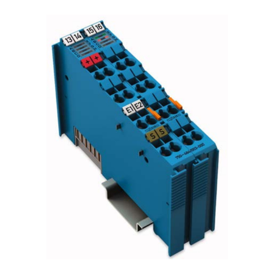
WAGO I/O-SYSTEM 750 Manual
Hide thumbs
Also See for I/O-SYSTEM 750:
- User manual ,
- Manual (450 pages) ,
- User's installation and configuration (335 pages)
Summary of Contents for WAGO I/O-SYSTEM 750
- Page 1 Fieldbus Independent I/O Modules 2 DO AC 230 V SSR, 3.0 A/ 30 s 750-522 Manual Version 1.0.3...
- Page 2 • General Copyright © 2006 by WAGO Kontakttechnik GmbH & Co. KG All rights reserved. WAGO Kontakttechnik GmbH & Co. KG Hansastraße 27 D-32423 Minden Phone: +49 (0) 571/8 87 – 0 Fax: +49 (0) 571/8 87 – 1 69 E-Mail: info@wago.com...
-
Page 3: Table Of Contents
750-522 [2 DO AC 230 V SSR, 3.0 A/ 30 s] ........7 2.1.1.1 View....................7 2.1.1.2 Description..................7 2.1.1.3 Display Elements ................9 2.1.1.4 Schematic Diagram................. 9 2.1.1.5 Technical Data ................10 2.1.1.6 Process image................11 2.1.2 Contact Protective Circuit for Relay Modules ........12 WAGO-I/O-SYSTEM 750 I/O Modules... -
Page 4: Important Comments
All other changes to the hardware and/or software and the non-conforming use of the components entail the exclusion of liability on part of WAGO Kon- takttechnik GmbH & Co. KG. -
Page 5: Symbols
Routines or advice for efficient use of the device and software optimization. More information References on additional literature, manuals, data sheets and INTERNET pages 1.3 Number Notation Number Code Example Note Decimal normal notation Hexadecimal 0x64 C notation Binary '100' Within ', '0110.0100' Nibble separated with dots WAGO-I/O-SYSTEM 750 I/O Modules... -
Page 6: Safety Notes
1.5 Scope This manual describes the Digital Input Module 750-522 2 DO AC 230 V SSR, 3.0 A/ 30 s of the modular WAGO-I/O-SYSTEM 750. Handling, assembly and start-up are described in the manual of the Fieldbus Coupler. Therefore this documentation is valid only in the connection with the appropriate manual. -
Page 7: O Modules
By closing a relay, the field power applied is switched to the second relay con- nection DO1 or DO2. The control of the semiconductor outputs is fully isolated using the internal system voltage. The outputs are switched at the zero cross. WAGO-I/O-SYSTEM 750 I/O Modules... - Page 8 Examples of protection circuits can be seen in the section 2.1.2 "Contact Protective Circuit for Relay Modules". The output module 750-522 can be used with all couplers/controllers of the WAGO-I/O-SYSTEM 750. WAGO-I/O-SYSTEM 750 I/O Modules...
-
Page 9: Display Elements
Output DO 2: activated g052202x Output DO 2: normal operation Error DO 2 Output DO 2: overload 2.1.1.4 Schematic Diagram DO 1 DO 2 Logic & 230V 230V Status Error 750-522 Fig. 2.1.1-3: 2-Channel Digital Output Module 750-522 g052201e WAGO-I/O-SYSTEM 750 I/O Modules... -
Page 10: Technical Data
II 3 GD EEx nA II T4 Conformity Marking More Information Detailed references to the approvals are listed in the document "Overview Approvals WAGO-I/O-SYSTEM 750", which you can find on the CD ROM ELECTRONICC Tools and Docs (Item-No.: 0888-0412) or in the internet under: www.wago.com... -
Page 11: Process Image
Error bit goes high in case of an overload at the output Output process values of module 750-522 Output bit Meaning controls DO 2* controls DO 1* Channel 2 Channel 1 DO 1, DO 2: Outputs switched into zero crossing WAGO-I/O-SYSTEM 750 I/O Modules... -
Page 12: Contact Protective Circuit For Relay Modules
- attenuation only above g051214e Advantages: R/C combination - HF attenuation via power storage - suitable for A.C. voltage medium to - level-independent attenua- Load short tion Disadvantages: - exact dimensioning re- g051215e quired - high inrush current WAGO-I/O-SYSTEM 750 I/O Modules... - Page 13 Digital Output Modules • 13 Contact Protective Circuit for Relay Modules WAGO-I/O-SYSTEM 750 I/O Modules...
- Page 14 WAGO Kontakttechnik GmbH & Co. KG Postfach 2880 • D-32385 Minden Hansastraße 27 • D-32423 Minden Phone: 05 71/8 87 – 0 Fax: 05 71/8 87 – 1 69 E-Mail: info@wago.com Internet: http://www.wago.com...


Need help?
Do you have a question about the I/O-SYSTEM 750 and is the answer not in the manual?
Questions and answers