
Related Manuals for WAGO 750-606


Summary of Contents for WAGO 750-606
- Page 1 Manual WAGO-I/O-SYSTEM 750 750-606 24 V DC 1.0 A power supply Ex i Supply Module 24 V DC, 1.0 A Ex i Version 1.4.0 valid from HW version 03...
- Page 2 WAGO-I/O-SYSTEM 750 750-606 24 V DC 1.0 A power supply Ex i © 2017 WAGO Kontakttechnik GmbH & Co. KG All rights reserved. WAGO Kontakttechnik GmbH & Co. KG Hansastraße 27 D-32423 Minden Phone: +49 (0) 571/8 87 – 0 Fax: +49 (0) 571/8 87 –...
-
Page 3: Table Of Contents
WAGO-I/O-SYSTEM 750 Table of Contents 750-606 24 V DC 1.0 A power supply Ex i Table of Contents Notes about this Documentation ............. 5 Validity of this Documentation..............5 Copyright ....................5 Symbols ....................6 Number Notation ..................8 Font Conventions ................... 8 Important Notes .................. - Page 4 Table of Contents WAGO-I/O-SYSTEM 750 750-606 24 V DC 1.0 A power supply Ex i Marking Configuration Examples ............40 7.1.1 Marking for Europe According to ATEX and IECEx ......40 7.1.2 Marking for America (NEC) and Canada (CEC) ....... 44 Installation Regulations.................
-
Page 5: Notes About This Documentation
This documentation is only applicable to the I/O module 750-606 (24 V DC 1.0 A power supply Ex i). The I/O module 750-606 shall only be installed and operated according to the instructions in this manual and in the manual for the used fieldbus coupler/controller. -
Page 6: Symbols
Notes about this Documentation WAGO-I/O-SYSTEM 750 750-606 24 V DC 1.0 A power supply Ex i Symbols Personal Injury! Indicates a high-risk, imminently hazardous situation which, if not avoided, will result in death or serious injury. Personal Injury Caused by Electric Current! Indicates a high-risk, imminently hazardous situation which, if not avoided, will result in death or serious injury. - Page 7 WAGO-I/O-SYSTEM 750 Notes about this Documentation 750-606 24 V DC 1.0 A power supply Ex i Additional Information: Refers to additional information which is not an integral part of this documentation (e.g., the Internet). Manual Version 1.4.0 valid from HW version 03...
-
Page 8: Number Notation
Notes about this Documentation WAGO-I/O-SYSTEM 750 750-606 24 V DC 1.0 A power supply Ex i Number Notation Table 1: Number Notation Number Code Example Note Decimal Normal notation Hexadecimal 0x64 C notation Binary '100' In quotation marks, nibble separated '0110.0100'... -
Page 9: Important Notes
2.1.1 Subject to Changes WAGO Kontakttechnik GmbH & Co. KG reserves the right to provide for any alterations or modifications. WAGO Kontakttechnik GmbH & Co. KG owns all rights arising from the granting of patents or from the legal protection of utility patents. -
Page 10: Technical Condition Of Specified Devices
Important Notes WAGO-I/O-SYSTEM 750 750-606 24 V DC 1.0 A power supply Ex i certificate must be obtained that confirms the correct installation of the system in a housing or switch cabinet. 2.1.4 Technical Condition of Specified Devices The devices to be supplied ex works are equipped with hardware and software configurations, which meet the individual application requirements. -
Page 11: Safety Advice (Precautions)
Install the device only in appropriate housings, cabinets or in electrical operation rooms! The WAGO-I/O-SYSTEM 750 and its components are an open system. As such, install the system and its components exclusively in appropriate housings, cabinets or in electrical operation rooms. Allow access to such equipment and fixtures to authorized, qualified staff only by means of specific keys or tools. - Page 12 Important Notes WAGO-I/O-SYSTEM 750 750-606 24 V DC 1.0 A power supply Ex i Do not use any contact spray! Do not use any contact spray. The spray may impair contact area functionality in connection with contamination. Do not reverse the polarity of connection lines! Avoid reverse polarity of data and power supply lines, as this may damage the devices involved.
-
Page 13: Device Description
750-606 24 V DC 1.0 A power supply Ex i Device Description The I/O module 750-606 (24 V DC 1.0 A power supply Ex i) provides 24 VDC power to the 750 Series. Furthermore, it separates the intrinsically safe part from the non-intrinsically safe part of the fieldbus node and makes diagnostic information available in the process image. -
Page 14: Table 3: Compatibility List 750-606
Device Description WAGO-I/O-SYSTEM 750 750-606 24 V DC 1.0 A power supply Ex i Table 3: Compatibility list 750-606 Fieldbus Couplers/ Software – Bus System Item No. Controllers Version No. 750-829 Programmable BACnet 750-830 Fieldbus Controllers 750-831 750-337 750-337/025-000 750-338... - Page 15 WAGO-I/O-SYSTEM 750 Device Description 750-606 24 V DC 1.0 A power supply Ex i 750-819 Programmable ® LonWorks 750-819/005-000 Fieldbus Controllers 750-819/009-000 750-315/300-000 Fieldbus Coupler 750-316/300-000 MODBUS 750-815/300-000 Programmable Fieldbus Controllers 750-816/300-000 750-8202 750-8202/025-001 750-8202/025-002 Programmable PFC200 Fieldbus Controllers 750-8203...
-
Page 16: View
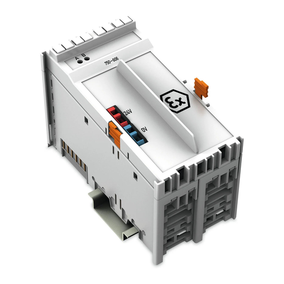
Device Description WAGO-I/O-SYSTEM 750 750-606 24 V DC 1.0 A power supply Ex i View Figure 1: View </dg_ Table 4:Legend for Figure “View” No. Explanation For details, see Section Marking options using the Mini- Status LEDs “Device Description” > “Display Elements”... -
Page 17: Connectors
WAGO-I/O-SYSTEM 750 Device Description 750-606 24 V DC 1.0 A power supply Ex i Connectors 3.2.1 Data Contacts/Internal Bus Communication between the fieldbus coupler/controller and the I/O modules as well as the system supply of the I/O modules is carried out via the internal bus. It is comprised of 6 data contacts, which are available as self-cleaning gold spring contacts. -
Page 18: Power Jumper Contacts/Field Supply
750-606 24 V DC 1.0 A power supply Ex i 3.2.2 Power Jumper Contacts/Field Supply The power supply module 750-606 has 2 self-cleaning power jumper contacts that transmit power for the field side. The contacts on the right side of the power supply module are designed as spring contacts. -
Page 19: Cage Clamp ® Connectors
WAGO-I/O-SYSTEM 750 Device Description 750-606 24 V DC 1.0 A power supply Ex i ® 3.2.3 CAGE CLAMP Connectors ® Figure 4: CAGE CLAMP Connectors ® Table 6: Legend for Figure “CAGE CLAMP Connectors” Designation Connector Function +24 V Supply voltage 24 V DC (−25 % … +30 %) -
Page 20: Display Elements
Device Description WAGO-I/O-SYSTEM 750 750-606 24 V DC 1.0 A power supply Ex i Display Elements Figure 5: Display Elements Table 7: Legend for the “Display Elements” Figure Designation State Function No power supply at the infeed input Power supply status –... -
Page 21: Schematic Diagram
WAGO-I/O-SYSTEM 750 Device Description 750-606 24 V DC 1.0 A power supply Ex i Schematic Diagram Figure 6: Schematic Switching Diagram Manual Version 1.4.0 valid from HW version 03... -
Page 22: Technical Data
Device Description WAGO-I/O-SYSTEM 750 750-606 24 V DC 1.0 A power supply Ex i Technical Data 3.6.1 Device Data Table 8: Technical Data – Device Width 48 mm Height (from upper edge of 35 DIN rail) 64 mm Depth 100 mm Weight Approx. -
Page 23: Connection Type
WAGO-I/O-SYSTEM 750 Device Description 750-606 24 V DC 1.0 A power supply Ex i 3.6.5 Connection Type Table 12: Technical Data – Field Wiring ® Wire connection CAGE CLAMP Cross section 0.08 mm² … 1.5 mm² / AWG 28-16 Stripped lengths 5 mm …... -
Page 24: Approvals
Ordinary Location Korea Certification MSIP-REM-W43-SPP750 The following Ex approvals have been granted to 750-606 I/O modules: TÜV 12 ATEX 106032 X I M2 Ex d I Mb II 3 G Ex ec IIC T4 Gc II 3 D Ex tc IIIC T135°C Dc IECEx TUN 12.0039 X... - Page 25 WAGO-I/O-SYSTEM 750 Device Description 750-606 24 V DC 1.0 A power supply Ex i UL E198726 for Use in Hazardous Locations Cl I, Div 2, Group A, B, C, D, T4 Manual Version 1.4.0 valid from HW version 03...
- Page 26 Device Description WAGO-I/O-SYSTEM 750 750-606 24 V DC 1.0 A power supply Ex i The following ship approvals have been granted to 750-606 I/O modules: ABS (American Bureau of Shipping) Federal Maritime and Hydrographic Agency BV (Bureau Veritas) DNV (Det Norske Veritas)
-
Page 27: Standards And Guidelines
WAGO-I/O-SYSTEM 750 Device Description 750-606 24 V DC 1.0 A power supply Ex i Standards and Guidelines 750-606 I/O modules meet the following standards and guidelines: EU Directive 2014/34/EU Explosive atmosphere EN 60079-0 Devices – General requirements Explosive atmosphere IEC 60079-7 Equipment protection by increased safety "e"... - Page 28 Device Description WAGO-I/O-SYSTEM 750 750-606 24 V DC 1.0 A power supply Ex i Explosive atmospheres CAN/CSA-C22.2 No. 60079-15 Equipment Protection by Intrinsic Safety "n" UL Standard for Safety – UL 508 for Industrial Control Equipment American National Standard –...
-
Page 29: Process Image
WAGO-I/O-SYSTEM 750 Process Image 750-606 24 V DC 1.0 A power supply Ex i Process Image Mapping of process data in the process image of fieldbus systems The representation of the I/O modules’ process data in the process image depends on the fieldbus coupler/controller used. Please take this information as well as the particular design of the respective control/status bytes from the section “Fieldbus Specific Design of the Process Data”... -
Page 30: Mounting
Don't forget the bus end module! Always plug a bus end module (750-600) onto the end of the fieldbus node! You must always use a bus end module at all fieldbus nodes with WAGO-I/O- SYSTEM 750 fieldbus couplers/controllers to guarantee proper data transfer. -
Page 31: Inserting And Removing Devices
WAGO-I/O-SYSTEM 750 Mounting 750-606 24 V DC 1.0 A power supply Ex i Inserting and Removing Devices Perform work on devices only if they are de-energized! Working on energized devices can damage them. Therefore, turn off the power supply before working on the devices. -
Page 32: Removing The I/O Module
Mounting WAGO-I/O-SYSTEM 750 750-606 24 V DC 1.0 A power supply Ex i 5.2.2 Removing the I/O Module Remove the I/O module from the assembly by pulling both release tabs. Figure 9: Removing the I/O Module (Example) Electrical connections for data or power jumper contacts are disconnected when removing the I/O module. -
Page 33: Connect Devices
WAGO-I/O-SYSTEM 750 Connect Devices 750-606 24 V DC 1.0 A power supply Ex i Connect Devices ® Connecting a Conductor to the CAGE CLAMP ® The WAGO CAGE CLAMP connection is appropriate for solid, stranded and finely stranded conductors. ®... -
Page 34: Power Supply Concept
Connect Devices WAGO-I/O-SYSTEM 750 750-606 24 V DC 1.0 A power supply Ex i Power Supply Concept Keep the air and creep distances between intrinsically safe segments! The maximum current available from the 750-606 or 750-625/000-001 Ex-i Supply Module is 1 A. -
Page 35: Figure 11: Supply Principle Ex I
WAGO-I/O-SYSTEM 750 Connect Devices 750-606 24 V DC 1.0 A power supply Ex i Figure 11: Supply Principle Ex i Table 17: Legend for the “Ex i Power Supply Concept” Figure No. Explanation Fieldbus coupler/controller Ex i supply module (750-606, 750-625/000-001) -
Page 36: Figure 12: Overvoltage Categories
Connect Devices WAGO-I/O-SYSTEM 750 750-606 24 V DC 1.0 A power supply Ex i Figure 12: Overvoltage Categories Table 18: Legend for Figure “Overvoltage Categories” Explanation Fieldbus coupler/controller Filter module Ex i supply module Ex i I/O modules End module Both overvoltage categories and rated surge voltage acc. -
Page 37: Power Supply Concept In Marine Applications
WAGO-I/O-SYSTEM 750 Connect Devices 750-606 24 V DC 1.0 A power supply Ex i 6.2.1 Power Supply Concept in Marine Applications The appropriate filter module is required when using Ex i I/O modules in marine applications! Power supply to the Ex i supply module shall be provided via the appropriate filter module when using Ex i I/O modules in marine applications! Modules approved to category EMC1 (marine applications): 750-626 or 750-626/020-000. -
Page 38: Figure 14: Power Supply Concept, Category Emc2 (Marine Applications)
Connect Devices WAGO-I/O-SYSTEM 750 750-606 24 V DC 1.0 A power supply Ex i Figure 14: Power Supply Concept, Category EMC2 (Marine Applications) Table 20: Legend for Figure “Power Supply Concept, Category EMC2 (Marine Applications)” Explanation Fieldbus coupler/controller Filter module (750-626, 750-626/020-000, 750-624, 750-624/020-000) -
Page 39: Use In Hazardous Environments
WAGO-I/O-SYSTEM 750 Use in Hazardous Environments 750-606 24 V DC 1.0 A power supply Ex i Use in Hazardous Environments The WAGO-I/O-SYSTEM 750 (electrical equipment) is designed for use in Zone 2 hazardous areas. The following sections include both the general identification of components (devices) and the installation regulations to be observed. -
Page 40: Marking Configuration Examples
Use in Hazardous Environments WAGO-I/O-SYSTEM 750 750-606 24 V DC 1.0 A power supply Ex i Marking Configuration Examples 7.1.1 Marking for Europe According to ATEX and IECEx Figure 15: Marking Example According to ATEX and IECEx Figure 16: Text Detail – Marking Example According to ATEX and IECEx Manual Version 1.4.0 valid from HW version 03... -
Page 41: Table 21: Description Of Marking Example According To Atex And Iecex
WAGO-I/O-SYSTEM 750 Use in Hazardous Environments 750-606 24 V DC 1.0 A power supply Ex i Table 21: Description of Marking Example According to ATEX and IECEx Marking Description TUEV 07 ATEX 554086 X Approving authority resp. certificate numbers IECEx TUN 09.0001 X... -
Page 42: Figure 17: Marking Example For Approved Ex I I/O Module According To Atex
Use in Hazardous Environments WAGO-I/O-SYSTEM 750 750-606 24 V DC 1.0 A power supply Ex i Figure 17: Marking Example for Approved Ex i I/O Module According to ATEX and IECEx Figure 18: Text Detail – Marking Example for Approved Ex i I/O Module According to ATEX and... -
Page 43: Table 22: Description Of Marking Example For Approved Ex I I/O Module According To Atex And Iecex
WAGO-I/O-SYSTEM 750 Use in Hazardous Environments 750-606 24 V DC 1.0 A power supply Ex i Table 22: Description of Marking Example for Approved Ex i I/O Module According to ATEX and IECEx Marking Description TUEV 12 ATEX 106032 X Approving authority resp. -
Page 44: Marking For America (Nec) And Canada (Cec)
Use in Hazardous Environments WAGO-I/O-SYSTEM 750 750-606 24 V DC 1.0 A power supply Ex i 7.1.2 Marking for America (NEC) and Canada (CEC) Figure 19: Marking Example According to NEC Figure 20: Text Detail – Marking Example According to NEC 500... -
Page 45: Figure 21: Text Detail - Marking Example For Approved Ex I I/O Module
WAGO-I/O-SYSTEM 750 Use in Hazardous Environments 750-606 24 V DC 1.0 A power supply Ex i Figure 21: Text Detail – Marking Example for Approved Ex i I/O Module According to NEC 505 Table 24: Description of Marking Example for Approved Ex i I/O Module According to NEC 505... -
Page 46: Figure 23: Text Detail - Marking Example For Approved Ex I I/O Modules
Use in Hazardous Environments WAGO-I/O-SYSTEM 750 750-606 24 V DC 1.0 A power supply Ex i Figure 23: Text Detail – Marking Example for Approved Ex i I/O Modules According to CEC 18 attachment J Table 26: Description of Marking Example for Approved Ex i I/O Modules According to CEC 18... -
Page 47: Installation Regulations
WAGO-I/O-SYSTEM 750 Use in Hazardous Environments 750-606 24 V DC 1.0 A power supply Ex i Installation Regulations For the installation and operation of electrical equipment in hazardous areas, the valid national and international rules and regulations which are applicable at the installation location must be carefully followed. - Page 48 Use in Hazardous Environments WAGO-I/O-SYSTEM 750 750-606 24 V DC 1.0 A power supply Ex i Explosive atmosphere occurring simultaneously with assembly, installation or repair work must be ruled out. Among other things, these include the following activities • Insertion and removal of components •...
-
Page 49: Special Notes Regarding Ansi/Isa Ex
WAGO-I/O-SYSTEM 750 Use in Hazardous Environments 750-606 24 V DC 1.0 A power supply Ex i 7.2.2 Special Notes Regarding ANSI/ISA Ex For ANSI/ISA Ex acc. to UL File E198726, the following additional requirements apply: • Use in Class I, Division 2, Group A, B, C, D or non-hazardous areas only •... -
Page 50: Appendix
Appendix WAGO-I/O-SYSTEM 750 750-606 24 V DC 1.0 A power supply Ex i Appendix Rated Surge Voltage Table 27: Rated Surge Voltage Nominal voltage of Line-to-neutral voltage, Rated surge voltage the power supply system derived from the nominal (mains) acc. to IEC 60038 3... -
Page 51: List Of Figures
WAGO-I/O-SYSTEM 750 List of Figures 750-606 24 V DC 1.0 A power supply Ex i List of Figures Figure 1: View ....................16 Figure 2: Data Contacts ..................17 Figure 3: Power Jumper Contacts ..............18 ® Figure 4: CAGE CLAMP Connectors ..............19 Figure 5: Display Elements.................20... -
Page 52: List Of Tables
List of Tables WAGO-I/O-SYSTEM 750 750-606 24 V DC 1.0 A power supply Ex i List of Tables Table 1: Number Notation ................... 8 Table 2: Font Conventions .................. 8 Table 3: Compatibility list 750-606..............14 Table 4:Legend for Figure “View” ...............16 Table 5: Legend for Figure “Power Jumper Contacts”... - Page 53 WAGO-I/O-SYSTEM 750 750-606 24 V DC 1.0 A power supply Ex i Manual Version 1.4.0 valid from HW version 03...
- Page 54 WAGO Kontakttechnik GmbH & Co. KG Postfach 2880 • 32385 Minden Hansastraße 27 • 32423 Minden Phone: 0571/887 – 0 Fax: 0571/887 – 169 E-Mail: info@wago.com Internet: http://www.wago.com...
Need help?
Do you have a question about the 750-606 and is the answer not in the manual?
Questions and answers