Table of Contents
Advertisement
Quick Links
Pos: 2 /Dokumentation allgemein/Einband/Einband Deckblatt @ 9\mod_1285229289866_0.doc @ 64941 @ @ 1
Manual
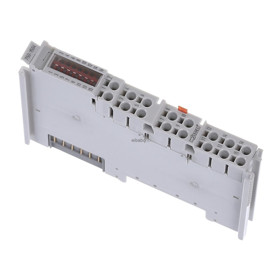
WAGO-I/O-SYSTEM 750
16DO 24V DC 0.5A
750-1504
16-Channel Digital Output Module 24 V DC, High-side
switching
Version 1.0.1
Pos: 3 /Alle Serien (Allgemeine Module)/Hinweise zur Dokumentation/Impressum - allgemeine Angaben, Anschriften, Telefonnummern und E-Mail-Adressen @ 3\mod_1219151118203_21.doc @ 21060 @ @ 1
Advertisement
Chapters
Table of Contents

Related Manuals for WAGO 750-1504


Summary of Contents for WAGO 750-1504
- Page 1 Pos: 2 /Dokumentation allgemein/Einband/Einband Deckblatt @ 9\mod_1285229289866_0.doc @ 64941 @ @ 1 Manual WAGO-I/O-SYSTEM 750 16DO 24V DC 0.5A 750-1504 16-Channel Digital Output Module 24 V DC, High-side switching Version 1.0.1 Pos: 3 /Alle Serien (Allgemeine Module)/Hinweise zur Dokumentation/Impressum - allgemeine Angaben, Anschriften, Telefonnummern und E-Mail-Adressen @ 3\mod_1219151118203_21.doc @ 21060 @ @ 1...
- Page 2 WAGO-I/O-SYSTEM 750 750-1504 16DO 24V DC 0.5A © 2012 by WAGO Kontakttechnik GmbH & Co. KG All rights reserved. WAGO Kontakttechnik GmbH & Co. KG Hansastraße 27 D-32423 Minden Phone: +49 (0) 571/8 87 – 0 Fax: +49 (0) 571/8 87 – 1 69 E-Mail: info@wago.com...
-
Page 3: Table Of Contents
WAGO-I/O-SYSTEM 750 Table of Contents 750-1504 16DO 24V DC 0.5A Po s: 5 /Dokumentation allgemein/Verzeichnisse/Inhaltsverzeichnis - ohne Gliederung - und Verzeichnis @ 3\mod_1219151230875_21.doc @ 21063 @ @ 1 Table of Contents Notes about this Documentation..............5 Validity of this Documentation..............5 Copyright.................... - Page 4 Table of Contents WAGO-I/O-SYSTEM 750 750-1504 16DO 24V DC 0.5A 7.2.2 Examples of Connection..............32 List of Figures ...................... 33 List of Tables......................34 === Ende der Liste für Textmarke Verzeichnis_vorne === Manual Version 1.0.1...
-
Page 5: Notes About This Documentation
Care must also be taken to ensure that any supplement to these instructions are included, if applicable. s: 9 /Serie 750 (WAGO-I/O-SYSTEM)/Hinweise zur Dokumentation/Gültigkeitsbereich Dokumentation Busklemme 750-xxxx, ohne Variantenangabe @ 4\mod_1237986650812_21.doc @ 29020 @ 2 @ 1 Validity of this Documentation This documentation is only applicable to the I/O module 750-1504 (16DO 24V DC 0.5A) of the WAGO-I/O-SYSTEM 750 series. -
Page 6: Symbols
Notes about this Documentation WAGO-I/O-SYSTEM 750 750-1504 16DO 24V DC 0.5A s: 11.3 /Alle Serien (Allgemeine Module)/Hinweise zur Dokumentation/Symbole @ 3\mod_1217394197593_21.doc @ 21010 @ 2 @ 1 Symbols Personal Injury! Indicates a high-risk, imminently hazardous situation which, if not avoided, will result in death or serious injury. - Page 7 WAGO-I/O-SYSTEM 750 Notes about this Documentation 750-1504 16DO 24V DC 0.5A Additional Information: Refers to additional information which is not an integral part of this documentation (e.g., the Internet). s: 11.4 /Dokumentation allgemein/Gliederungselemente/---Seitenwechsel--- @ 3\mod_1221108045078_0.doc @ 21810 @ @ 1 Manual Version 1.0.1...
-
Page 8: Number Notation
Notes about this Documentation WAGO-I/O-SYSTEM 750 750-1504 16DO 24V DC 0.5A s: 11.5 /Alle Serien (Allgemeine Module)/Hinweise zur Dokumentation/Zahlensysteme @ 3\mod_1221059454015_21.doc @ 21711 @ 2 @ 1 Number Notation Table 1: Number Notation Number code Example Note Decimal Normal notation... -
Page 9: Important Notes
All changes to the coupler or controller should always be carried out by qualified personnel with sufficient skills in PLC programming. Po s: 14.5 /Serie 750 (WAGO-I/O-SYSTEM)/Wichtige Erläuterungen/Bestimmungsgemäße Verwendung 750-xxxx @ 3\mod_1224064151234_21.doc @ 24070 @ 3 @ 1 2.1.3 Use of the 750 Series in Compliance with Underlying... -
Page 10: Technical Condition Of Specified Devices
The components to be supplied Ex Works, are equipped with hardware and software configurations, which meet the individual application requirements. WAGO Kontakttechnik GmbH & Co. KG will be exempted from any liability in case of changes in hardware or software as well as to non-compliant usage of components. -
Page 11: Safety Advice (Precautions)
All power sources to the device shall be switched off prior to performing any installation, repair or maintenance work. s: 14.10.2 /Serie 750 (WAGO-I/O-SYSTEM)/Wichtige Erläuterungen/Sicherheitshinweise/Gefahr/Gefahr: Einbau 0750-xxxx nur in Gehäusen, Schränken oder elektrischen Betriebsräumen! @ 6\mod_1260180556692_21.doc @ 46731 @ @ 1 Installation only in appropriate housings, cabinets or in electrical operation rooms! The WAGO-I/O-SYSTEM 750 and its components are an open system. - Page 12 Important Notes WAGO-I/O-SYSTEM 750 750-1504 16DO 24V DC 0.5A Do not use any contact spray! Do not use any contact spray. The spray may impair contact area functionality in connection with contamination. s: 14.11.5 /Alle Serien (Allgemeine Module)/Wichtige Erläuterungen/Sicherheitshinweise/Achtung/Achtung: Verpolung vermeiden! @ 6\mod_1260184045744_21.doc @ 46767 @ @ 1...
-
Page 13: Device Description
The meaning of the LEDs is described in the “Display Elements” section. Po s: 17.11 /Serie 750 (WAGO-I/O-SYSTEM)/Gerätebeschreibung/Beschreibung/Versorgung/Versorgung 24 V, 0 V über Leistungskontakte Standard @ 3\mod_1226498974531_21.doc @ 25020 @ @ 1 The I/O module receives the 24V voltage supply for the field level from an upstream I/O module or from the fieldbus coupler/controller via the power contacts used as blade contacts. - Page 14 The field level and the system level are electrically isolated from one another. Po s: 17.15 /Serie 750 (WAGO-I/O-SYSTEM)/Gerätebeschreibung/Beschreibung/Versorgung/Anordnung unter Berücksichtigung der Leistungskontakte beliebig @ 3\mod_1233756233468_21.doc @ 27099 @ @ 1 With consideration of the power jumper contacts, the individual modules can be arranged in any combination when configuring the fieldbus node.
-
Page 15: View
19 /Alle Serien (Allgemeine Module)/Überschriften für alle Serien/Ansicht - Überschrift 2 @ 4\mod_1240984217343_21.doc @ 31958 @ 2 @ 1 View Po s: 20 /Serie 750 (WAGO-I/O-SYSTEM)/Gerätebeschreibung/Ansicht/Digitalausgangsklemmen/Ansicht 750-150x 16 DO CAGE CLAMP @ 3\mod_1224766395937_21.doc @ 24653 @ @ 1 750-15XX... -
Page 16: Connectors
Do not place the I/O modules on the gold spring contacts in order to avoid soiling or scratching! s: 24.3 /Serie 750 (WAGO-I/O-SYSTEM)/Wichtige Erläuterungen/Sicherheitshinweise/Achtung/Achtung: ESD - Auf gute Erdung der Umgebung achten! @ 7\mod_1266318538667_21.doc @ 50708 @ @ 1 Ensure that the environment is well grounded! The modules are equipped with electronic components that may be destroyed by electrostatic discharge. -
Page 17: Power Contacts/Field Supply
Figure 3: Power jumper contacts Po s: 27.3 /Serie 750 (WAGO-I/O-SYSTEM)/Wichtige Erläuterungen/Sicherheitshinweise/Achtung/Achtung: Maximaler Strom Leistungskontakte 10 A @ 3\mod_1226499143500_21.doc @ 25029 @ @ 1 Do not exceed maximum current via power contacts! The maximum current to flow through the power contacts is 10 A. -
Page 18: Cage Clamp Connections
29 /Serie 750 (WAGO-I/O-SYSTEM)/Gerätebeschreibung/Anschlüsse/CAGE CLAMP-Anschlüsse - Überschrift 3 @ 6\mod_1256296337770_21.doc @ 43674 @ 3 @ 1 ® 3.2.3 CAGE CLAMP Connections Po s: 30 /Serie 750 (WAGO-I/O-SYSTEM)/Gerätebeschreibung/Anschlüsse/Digitalausgangsklemmen/Anschlüsse 750-150x 16 DO CAGE CLAMP @ 3\mod_1232518817578_21.doc @ 26488 @ @ 1 Table 5: Connections Connection Channel Designation Function... -
Page 19: Display Elements
Po s: 34 /Alle Serien (Allgemeine Module)/Überschriften für alle Serien/Bedienelemente - Überschrift 2 @ 4\mod_1239191655456_21.doc @ 30439 @ 2 @ 1 Operating Elements Po s: 35 /Serie 750 (WAGO-I/O-SYSTEM)/Gerätebeschreibung/Bedienelemente/Bedienelemente Busklemme 750-xxxx nicht vorhanden @ 4\mod_1236322031125_21.doc @ 28063 @ @ 1 The I/O module 750-1504 has no operating elements. -
Page 20: Schematic Diagram
37 /Alle Serien (Allgemeine Module)/Überschriften für alle Serien/Schematisches Schaltbild - Überschrift 2 @ 4\mod_1240984441312_21.doc @ 31967 @ 2 @ 1 Schematic Diagram Po s: 38 /Serie 750 (WAGO-I/O-SYSTEM)/Gerätebeschreibung/Schematische Schaltbilder/Digitalausgangsklemmen/Schematisches Schaltbild 750-15xx 16 DO HSS CAGE CLAMP @ 3\mod_1232468079015_21.doc @ 26437 @ @ 1 750-15XX... -
Page 21: Technical Data
(Vcc = 24 V, R = 48 Ohm) max. Load Voltage quenching circuit |Vcc - 47 V| max. Po s: 42 /Serie 750 (WAGO-I/O-SYSTEM)/Gerätebeschreibung/Technische Daten/Technische Daten Anschl.technik CAGE CLAMP S 0,08...1,5mm2/AWG 28...16; 8...9mm/0,33in @ 12\mod_1335187597199_21.doc @ 94100 @ 3 @ 1 Manual Version 1.0.1... -
Page 22: Wire Connection
Device Description WAGO-I/O-SYSTEM 750 750-1504 16DO 24V DC 0.5A 3.6.5 Wire Connection Table 11: Technical Data Wire Connection ® Wire connection CAGE CLAMP Cross section 0.08 ... 1.5 mm² / AWG 28 ... 16 Stripped lengths 8 ... 9 mm / 0.33 in Po s: 43 /Dokumentation allgemein/Gliederungselemente/---Seitenwechsel--- @ 3\mod_1221108045078_0.doc @ 21810 @ @ 1... -
Page 23: Approvals
Pos: 55 /Alle Serien (Allgemeine Module)/Überschriften für alle Serien/Normen und Richtlinien - Überschrift 2 @ 4\mod_1242804031875_21.doc @ 33646 @ 2 @ 1 Standards and Guidelines Po s: 56 /Serie 750 (WAGO-I/O-SYSTEM)/Gerätebeschreibung/Normen und Richtlinien/EMV-Normen Busklemme 750-xxxx, ohne Variantenangabe @ 4\mod_1242803944015_21.doc @ 33642 @ @ 1 750-1504 I/O modules meet the following requirements on emission and immunity of interference: Po s: 57 /Alle Serien (Allgemeine Module)/Normen und Richtlinien/EMV CE-Störaussendung EN 61000-6-3: 2007 @ 4\mod_1242798094468_21.doc @ 33598 @ @ 1... -
Page 24: Assembly
DI4. s: 63.4 /Serie 750 (WAGO-I/O-SYSTEM)/Wichtige Erläuterungen/Sicherheitshinweise/Achtung/Achtung: Aneinanderreihen von Busklemmen nur bei offener Nut! @ 6\mod_1256193351448_21.doc @ 43417 @ @ 1 Assemble the I/O modules in rows only if the grooves are open! Please take into consideration that some bus modules have no or only a few power jumper contacts. -
Page 25: Inserting And Removing Devices
63.7 /Serie 750 (WAGO-I/O-SYSTEM)/Montieren/Geräte einfügen und entfernen - Überschrift 2 @ 3\mod_1231768483250_21.doc @ 25950 @ 2 @ 1 Inserting and Removing Devices Po s: 63.8 /Serie 750 (WAGO-I/O-SYSTEM)/Wichtige Erläuterungen/Sicherheitshinweise/Gefahr/Gefahr: Vorsicht bei der Unterbrechung von FE! @ 6\mod_1256193919214_21.doc @ 43423 @ @ 1 Use caution when interrupting the PE! Make sure that people or equipment are not placed at risk when removing an I/O module and the associated PE interruption. -
Page 26: Removing The I/O Module
(if any) to the fieldbus coupler/controller or to the previous or possibly subsequent I/O module are established. Po s: 63.11 /Serie 750 (WAGO-I/O-SYSTEM)/Montieren/Busklemme entfernen @ 4\mod_1239169375203_21.doc @ 30334 @ 3 @ 1 4.2.2 Removing the I/O Module Remove the I/O module from the assembly by pulling the release tab. -
Page 27: Connect Devices
65 /Alle Serien (Allgemeine Module)/Überschriften für alle Serien/Geräte anschließen - Überschrift 1 @ 3\mod_1234172889468_21.doc @ 27460 @ 1 @ 1 Connect Devices Po s: 66 /Serie 750 (WAGO-I/O-SYSTEM)/Anschließen/Leiter an CAGE CLAMP S anschließen - Überschrift 2 und Text @ 6\mod_1258964749000_21.doc @ 44640 @ 2 @ 1 ®... -
Page 28: Process Image
68 /Alle Serien (Allgemeine Module)/Überschriften für alle Serien/Prozessabbild - Überschrift 1 @ 4\mod_1240983067828_21.doc @ 31942 @ 1 @ 1 Process Image Po s: 69 /Serie 750 (WAGO-I/O-SYSTEM)/Prozessabbild Klemmenbus/Digitalausgangsklemmen/Prozessabbild 750-15xx 16 DO @ 3\mod_1232537349671_21.doc @ 26518 @ @ 1 Table 12: Outputbyte D0... -
Page 29: Using Interference-Free Io Modules In Safety Related Applications
Using Interference-Free IO Modules in Safety Related Applications 750-1504 16DO 24V DC 0.5A s: 71.1 /Serie 750 (WAGO-I/O-SYSTEM)/Einsatz in sicherheitsgerichteten Anwendungen/Einleitung - rückwirkungsfreie Busklemmen @ 6\mod_1258973397992_21.doc @ 44678 @ 1 @ 1 Using Interference-Free IO Modules in Safety Related Applications The 750-1504 I/O module is suited for use in interference-free safety circuits. -
Page 30: Important Notes
Using Interference-Free IO Modules in Safety Related Applications WAGO-I/O-SYSTEM 750 750-1504 16DO 24V DC 0.5A s: 71.4 /Serie 750 (WAGO-I/O-SYSTEM)/Einsatz in sicherheitsgerichteten An wendungen/Hinweise zum Einsatz in Sicherheitsanwendungen @ 6\mod_1258974811 438_21.doc @ 44688 @ 2 @ 1 Einsatz der rückwirkungsfreien Digitalausgangsklemme in Sicherheitsanwendungen... -
Page 31: Connecting The Io Module To Safety Switching Devices Or Safety Modules
Using Interference-Free IO Modules in Safety Related Applications 750-1504 16DO 24V DC 0.5A s: 71.6 /Serie 750 (WAGO-I/O-SYSTEM)/Einsatz in sicherheitsgerichteten Anwendungen/Allgemeiner Aufbau einer Potentialgruppe - rückwirkungsfreie Busklemmen @ 6\mod_1258972956853_21.doc @ 44661 @ 23 @ 1 Connecting the IO Module to Safety Switching Devices or Safety Modules 7.2.1... -
Page 32: Figure 12: Two-Channel Single-Pole Disconnection
Using Interference-Free IO Modules in Safety Related Applications WAGO-I/O-SYSTEM 750 750-1504 16DO 24V DC 0.5A s: 73 /Serie 750 (WAGO-I/O-SYSTEM)/Einsatz in sicherheitsgerichteten Anw endungen/Anschlussbeispiele/Anschlussbeispiel 16-Kanal-Digitalausgangsklemmen C C HSS in Sicherheitsanwendungen @ 6\mod_1259220807423_21.doc @ 45328 @ 3 @ 1 Einsatz der rückwirkungsfreien Digitalausgangsklemme in Sicherheitsanwendungen 7.2.2... - Page 33 WAGO-I/O-SYSTEM 750 List of Figures 750-1504 16DO 24V DC 0.5A Po s: 75 /Dokumentation allgemein/Verzeichnisse/Abbildungsverzeichnis - ohne Gliederung - und Verzeichnis @ 3\mod_1219222916765_21.doc @ 21080 @ @ 1 List of Figures Figure 1: View....................... 15 Figure 2: Data contacts..................16 Figure 3: Power jumper contacts................
- Page 34 List of Tables WAGO-I/O-SYSTEM 750 750-1504 16DO 24V DC 0.5A s: 77 /Dokumentation allgemein/Verzeichnisse/Tabellenverzeichnis - ohne Gliederung - und Verzeichnis @ 3\mod_1219222958703_21.doc @ 21084 @ @ 1 List of Tables Table 1: Number Notation..................8 Table 2: Font Conventions ..................8 Table 3: Caption acc.
- Page 35 WAGO-I/O-SYSTEM 750 750-1504 16DO 24V DC 0.5A Po s: 79 /Dokumentation allgemein/Einband/Einband Leerseite für gerade Seitenzahl @ 3\mod_1219230851078_0.doc @ 21123 @ @ 1 Manual Version 1.0.1...
- Page 36 Pos: 80 /Dokumentation allgemein/Einband/Einband Rückseite @ 9\mod_1285229376516_21.doc @ 64944 @ @ 1 WAGO Kontakttechnik GmbH & Co. KG Postfach 2880 • D-32385 Minden Hansastraße 27 • D-32423 Minden Phone: +49/5 71/8 87 – 0 Fax: +49/5 71/8 87 – 1 69 E-Mail: info@wago.com...
Need help?
Do you have a question about the 750-1504 and is the answer not in the manual?
Questions and answers