Siemens SIMOTION D410 Series Commissioning Manual
Hide thumbs
Also See for SIMOTION D410 Series:
- Commissioning manual (230 pages) ,
- Manual (110 pages) ,
- Manual (108 pages)
Table of Contents
Advertisement
Quick Links
SIMOTION SIMOTION SCOUT D410
SIMOTION
SIMOTION
D410
Commissioning Manual
Valid for SIMOTION D410 DP and D410 PN
05/2009
Preface
______________
Description
______________
Commissioning (hardware)
Configuring SIMOTION
______________
D410
______________
Commissioning (software)
______________
Maintenance and service
______________
Service and diagnostics
______________
Standards and approvals
______________
ESD guidelines
1
2
3
4
5
6
A
B
Advertisement
Table of Contents

Subscribe to Our Youtube Channel
Related Manuals for Siemens SIMOTION D410 Series


Summary of Contents for Siemens SIMOTION D410 Series
- Page 1 Preface SIMOTION SIMOTION SCOUT D410 ______________ Description ______________ Commissioning (hardware) SIMOTION Configuring SIMOTION ______________ D410 SIMOTION ______________ D410 Commissioning (software) ______________ Maintenance and service Commissioning Manual ______________ Service and diagnostics ______________ Standards and approvals ______________ ESD guidelines Valid for SIMOTION D410 DP and D410 PN 05/2009...
- Page 2 Note the following: WARNING Siemens products may only be used for the applications described in the catalog and in the relevant technical documentation. If products and components from other manufacturers are used, these must be recommended or approved by Siemens. Proper transport, storage, installation, assembly, commissioning, operation and maintenance are required to ensure that the products operate safely and without any problems.
-
Page 3: Preface
Preface Contents of the commissioning manual This manual is part of the SIMOTION D4xx documentation package, Edition 05/2009. This manual describes commissioning of the SIMOTION devices D410 DP and D410 PN. Information blocks in this manual The following information blocks describe the purpose and use of the commissioning manual. - Page 4 Technical support If you have any technical questions, please contact our hotline: Europe / Africa Phone +49 180 5050 222 (subject to charge) +49 180 5050 223 Internet http://www.siemens.com/automation/support-request Americas Phone +1 423 262 2522 +1 423 262 2200 E-mail mailto:techsupport.sea@siemens.com...
- Page 5 If you have any questions (suggestions, corrections) regarding this documentation, please fax or e-mail us at: +49 9131- 98 63315 E-mail mailto:docu.motioncontrol@siemens.com Siemens Internet address The latest information about SIMOTION products, product support, and FAQs can be found on the Internet at: ● General information: – http://www.siemens.de/simotion (German) –...
- Page 6 SIMOTION D410 can be recycled because it is made with low-polluting materials. For state-of-the art environmentally friendly recycling and disposal of your old modules, contact your Siemens representative. To locate your representative, point your browser to: Internet address (http://www.automation.siemens.com/partner). Further information / FAQs You can find additional information on this manual under FAQ at Internet address (http://support.automation.siemens.com/WW/view/en/27585482).
-
Page 7: Table Of Contents
Table of contents Preface ..............................3 Description............................... 11 System overview ..........................11 System components ........................13 SIMOTION D410 DP display .......................18 SIMOTION D410 PN display .......................21 The CompactFlash card.......................24 Licensing ............................25 Safety information ........................25 Commissioning (hardware) ........................27 Prerequisites for commissioning ....................27 Inserting the Compact Flash card....................28 Switching on the power supply ....................29 RESET button ..........................30... - Page 8 Table of contents 4.2.1 Overview ............................. 59 4.2.2 Accessing the drive wizard......................60 4.2.3 Configuring the components ....................... 61 4.2.4 Aligning HW Config ........................69 4.2.5 Downloading a project created offline to the target system ............70 4.2.6 Loading a project created offline to the CompactFlash Card............71 4.2.7 Downloading a project, including sources and additional data ...........
- Page 9 Table of contents 4.12.5 Manual speed controller optimization ..................124 4.13 Downloading and saving user data....................128 4.14 Deleting data ..........................129 4.14.1 Overview of data deletion ......................129 4.14.2 Resetting the memory of SIMOTION D410 ................130 4.14.3 Deleting user data from the CompactFlash Card ..............133 4.14.4 Restoring the default settings of SINAMICS Integrated ............134 4.14.5...
- Page 10 Table of contents 6.2.4 Restoring non-volatile data ....................... 179 6.2.5 Backing up diagnostic data and non-volatile data using IT DIAG..........181 Additional service and diagnostics options ................183 6.3.1 SIMOTION Task Profiler application..................183 6.3.2 Diagnostics using IT DIAG ......................183 Standards and approvals ........................
-
Page 11: Description
Description System overview Overview SIMOTION D is a drive-based version of SIMOTION based on the SINAMICS S120 drive family. With SIMOTION D, the SIMOTION PLC and motion control functionalities as well as the SINAMICS S120 drive software run on shared control hardware. SIMOTION D410 is a module drive system for single axes, which solves demanding drive tasks for a very wide range of industrial applications. - Page 12 Description 1.1 System overview System integration SIMOTION provides an optimized system platform for automation and drive solutions where the main focus is on motion control applications and technology tasks. The SIMOTION system is made up of three components: ● SIMOTION SCOUT Engineering System ●...
-
Page 13: System Components
Description 1.2 System components System components Overview SIMOTION D410 communicates with the components of the automation landscape via the following interfaces: ● PROFIBUS DP (SIMOTION D410 DP only) ● PROFINET (SIMOTION D410 PN only) ● DRIVE-CLiQ (DRIVE Component Link with IQ) ●... - Page 14 Description 1.2 System components PROFIBUS DP SIMOTION D410 DP can communicate via PROFIBUS DP interface to the following components: Table 1- 2 Components on PROFIBUS DP Components Function PG/PC programming device ... configures, sets parameters, programs and tests using the SIMOTION SCOUT Engineering System (ES).
- Page 15 Description 1.2 System components PROFINET SIMOTION D410 PN can communicate via PROFINET interface to the following components: Table 1- 3 Components on PROFINET Components Function The master computer (at ... communicates with other devices via Ethernet. company and production management level) PG/PC programming device ...
- Page 16 I/O system. You can find an up-to-date list of the I/O modules that can be used with SIMOTION at: Internet address (http://support.automation.siemens.com/WW/view/en/11886029). In addition to the I/O modules enabled for SIMOTION, in principle all certified standard PROFIBUS slaves (DP-V0/DP-V1/DP-V2) and PROFINET devices with RT and IRT real- time classes may be connected to SIMOTION D410.
- Page 17 Description 1.2 System components DRIVE-CLiQ DRIVE-CLiQ offers the following advantages within the DRIVE-CLiQ topology rules: ● Independent expansion of components possible ● Automatic detection of components by the Control Unit ● Standardized interfaces in all components ● Uniform diagnostics, right down to component level ●...
-
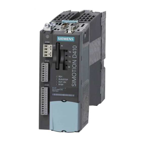
Page 18: Simotion D410 Dp Display
Description 1.3 SIMOTION D410 DP display SIMOTION D410 DP display View The following figure shows SIMOTION D410 DP with the interfaces and front elements. Figure 1-2 Location of interfaces and front elements in SIMOTION D410 DP Note The label underneath the mode selector lists the switch settings for the operating states of the SIMOTION D410. - Page 19 Description 1.3 SIMOTION D410 DP display Interfaces The SIMOTION D410 DP interfaces are described in the following tables. Table 1- 5 SIMOTION D410 interfaces Interface Description Digital inputs/outputs 12-pin Mini Combicon: X121 4 digital inputs: for connecting switches or proximity sensors •...
- Page 20 Description 1.3 SIMOTION D410 DP display The type plate below is located on the front of the SIMOTION D410 DP. Figure 1-4 SIMOTION D410 DP nameplate (example) Note The contents of the individual nameplate fields on the current module may differ from those described in this Manual (e.g., updated product status, space for approvals and identifications, etc.).
-
Page 21: Simotion D410 Pn Display
Description 1.4 SIMOTION D410 PN display SIMOTION D410 PN display View The following figure shows SIMOTION D410 PN with the interfaces and front elements. Figure 1-5 Location of interfaces and front elements in SIMOTION D410 PN D410 Commissioning Manual, 05/2009... - Page 22 Description 1.4 SIMOTION D410 PN display Interfaces The SIMOTION D410 PN interfaces are described in the following tables. Table 1- 6 SIMOTION D410 interfaces Interface Description Digital inputs/outputs 12-pin Mini Combicon: X121 4 digital inputs: for connecting switches and proximity sensors •...
- Page 23 Description 1.4 SIMOTION D410 PN display The following nameplate includes the MAC address of the PROFINET interface (ports X200 and X201) and is located on the front side of the module. Figure 1-7 SIMOTION PN nameplate (example) Note The contents of the individual nameplate fields on the current module may differ from those described in this Manual (e.g., updated product status, space for approvals and identifications, etc.).
-
Page 24: The Compactflash Card
Description 1.5 The CompactFlash card The CompactFlash card CompactFlash Card The following figure shows you all the information included on the nameplate of the CompactFlash Card (CF card). Figure 1-8 CompactFlash Card Pre-installed runtime licenses For versions V4.1 SP1 HF6 and higher, pre-installed licenses are printed on the type plate of the CF card as a Z option underneath the order number. -
Page 25: Licensing
Description 1.6 Licensing Licensing SIMOTION D410 licensing SIMOTION D410 is a modular drive system for single-axis applications. D410 contains the motion control technology functions for precisely one real axis (speed control, positioning, synchronous operation, cam). This means that these technology functions do not require an additional license. -
Page 27: Commissioning (Hardware)
Commissioning (hardware) Prerequisites for commissioning Prerequisites Prerequisites for commissioning the SIMOTION D410: ● You have completed installation and the wiring of your system with SIMOTION D410. ● A programming device / PC is available. Connecting a programming device / PC to SIMOTION D410 You can interconnect the programming device / PC: ●... -
Page 28: Inserting The Compact Flash Card
Commissioning (hardware) 2.2 Inserting the Compact Flash card Inserting the Compact Flash card Properties of the CF card The CF card is mandatory for operation of SIMOTION D410. The SIMOTION kernel and the drive control software (SINAMICS firmware) are installed on the CF card. The CompactFlash card must be inserted when you start up SIMOTION D410 in order to load the SIMOTION kernel. -
Page 29: Switching On The Power Supply
Commissioning (hardware) 2.3 Switching on the power supply Switching on the power supply Checking the system Check the system installation and wiring once again before you switch it on. Observe the safety-relevant items of the following checklist: ● Have you observed all ESD measures when handling the components? ●... -
Page 30: Reset Button
Commissioning (hardware) 2.4 RESET button Startup of SIMOTION D410 The startup of SIMOTION D410 is initiated after the power supply is activated: 1. The RDY LED is lit and the red RUN/STOP LED briefly lights up at the beginning of the startup sequence. -
Page 31: User Memory Concept
Commissioning (hardware) 2.5 User memory concept User memory concept 2.5.1 SIMOTION D410 memory model The following figure provides an overview of the SIMOTION D410 memory model. Figure 2-2 SIMOTION D410 memory model As a result, the SIMOTION Kernel (D410 firmware) contains the functions required for virtually all applications, and essentially acts as a PLC featuring an IEC 61131-3-compliant command set as well as system functions for controlling various components, such as inputs and outputs. -
Page 32: Properties Of The User Memories
Commissioning (hardware) 2.5 User memory concept 2.5.2 Properties of the user memories Non-volatile data Non-volatile data is used with the objective of retaining user- and system-relevant data when SIMOTION D410 is in de-energized state. You will find information about the area that can SIMOTION SCOUT be used for non-volatile data in the Configuration Manual. - Page 33 Commissioning (hardware) 2.5 User memory concept More information IP and DP parameters in non-volatile data The IP and DP parameters are loaded from configuration data on the CompactFlash Card during startup for use by the SIMOTION device. The SIMOTION D410 can use the addresses defined in these data to go online.
-
Page 34: Operator Actions And Their Impact On User Memory
Commissioning (hardware) 2.5 User memory concept CompactFlash Card The CompactFlash Card contains the following data: ● SIMOTION kernel ● Technology packages (TP) ● User data (units, configuration data, parameters, task configuration) ● IP parameters (IP address, subnet mask, router address) ●... - Page 35 Commissioning (hardware) 2.5 User memory concept Current RAM If you change the system variable values, these take immediate effect in the current RAM. New configuration data values are initially stored in the Next memory. Configuration data that take immediate effect are automatically transferred to the current RAM. Configuration data that will only become active following a RESTART on the technology object (set the restartactivation system variable to the ACTIVATE_RESTART value) are only written to the current RAM once the RESTART has taken place.
- Page 36 Commissioning (hardware) 2.5 User memory concept Backup of non-volatile data You have the following options for backing up non-volatile data on the CompactFlash Card: ● In the user program: With the "_savePersistentMemoryData" system function, the user program can back up the non-volatile data content to the CompactFlash Card.
- Page 37 Commissioning (hardware) 2.5 User memory concept Startup and non-volatile data The table below describes the startup situations which may develop in terms of the non- volatile data and how to handle such situations. Table 2- 3 Startup situations with non-volatile data Situa Initial condition Result...
- Page 38 Commissioning (hardware) 2.5 User memory concept System variable "device.persistentDataPowerMonitoring.persistentDataState" indicates the status of non-volatile data after startup: Table 2- 5 Status of non-volatile data after startup (persistentDataState system variable) Status Meaning FROM_RAM (1) Non-volatile data is activated in the SIMOTION device FROM_FILE (2) Non-volatile data was restored from the backup file FROM_BACKUP (3)
-
Page 39: Configuring Simotion D410
Please note that separate SIMOTION D firmware is available for PN V2.1 and PN V2.2. The required firmware can be found on the SCOUT DVD, as well as at: Internet address (http://support.automation.siemens.com/WW/view/en/31045047). For PN V2.2, you require STEP7 Version V5.4 SP4 (at least). - Page 40 Configuring SIMOTION D410 3.2 Inserting SIMOTION D410 into a project Communication with the programming device / PC via PROFIBUS (only for D410 DP) 1. Select the PROFIBUS interface from the "Properties - PROFIBUS/MPI" dialog box and confirm your selection with "OK". 2.
- Page 41 Configuring SIMOTION D410 3.2 Inserting SIMOTION D410 into a project 4. Select the PROFINET interface from the "Properties" dialog box and confirm your selection with "OK". 5. The connection to the programming device / PC is activated automatically and HW Config opens.
-
Page 42: Configuring The Profibus Dp Interface (Only D410 Dp)
Configuring SIMOTION D410 3.3 Configuring the PROFIBUS DP interface (only D410 DP) Configuring the PROFIBUS DP interface (only D410 DP) 3.3.1 General information about PROFIBUS DP communication Definition of PROFIBUS DP PROFIBUS DP is an international, open field bus standard specified in the European field bus Standard EN 50170 Part 2. -
Page 43: Assignment Of The Profibus Addresses In Hw Config
Configuring SIMOTION D410 3.3 Configuring the PROFIBUS DP interface (only D410 DP) 3.3.2 Assignment of the PROFIBUS addresses in HW Config Assigning PROFIBUS addresses Assign a PROFIBUS address to all devices before you start networking these in order to enable intercommunication. Note All PROFIBUS addresses you assign must be unique on the PROFIBUS subnet. -
Page 44: Operating Simotion D410 On Profibus Dp
Configuring SIMOTION D410 3.3 Configuring the PROFIBUS DP interface (only D410 DP) 3.3.3 Operating SIMOTION D410 on PROFIBUS DP. PROFIBUS DP interface (X21) SIMOTION D410 provides an interface for connecting to PROFIBUS DP. The interface supports transmission rates up to 12 Mbit/s. The X21 interface can be operated as a: ●... -
Page 45: Creating A New Profibus Dp Subnet
Configuring SIMOTION D410 3.3 Configuring the PROFIBUS DP interface (only D410 DP) 3.3.4 Creating a new PROFIBUS DP subnet The SIMOTION D410 device is networked using SIMOTION SCOUT. Set up your user- specific bus parameters for the PROFIBUS interface when you configure the network. Note The actions outlined below only need to be taken if you have not selected an interface when integrating SIMOTION D410 into the project (cf. -
Page 46: Setting The Dp Cycle And System Cycle Clocks
Configuring SIMOTION D410 3.3 Configuring the PROFIBUS DP interface (only D410 DP) 3.3.5 Setting the DP cycle and system cycle clocks All system clocks for SIMOTION D410 DP are based on the DP cycle of SINAMICS Integrated, which must be set in HW Config. In HW Config, double-click the SINAMICS drive at the integrated PROFIBUS. -
Page 47: Rules For Simotion D410 Dp
Configuring SIMOTION D410 3.3 Configuring the PROFIBUS DP interface (only D410 DP) 3.3.6 Rules for SIMOTION D410 DP Rules for synchronizing the system clocks You must adhere to the following rules when setting the DP cycle and SINAMICS cycle clocks: 1. -
Page 48: Operating The Profibus Interface (X21) As An Mpi Interface
Configuring SIMOTION D410 3.3 Configuring the PROFIBUS DP interface (only D410 DP) If any change to the DP cycle violates this rule you must also change the SINAMICS cycles. In order to change the cycles in the Expert list of SIMOTION SCOUT, select the "Control_Unit"... -
Page 49: Configuring Profinet (Only For D410 Pn)
Configuring SIMOTION D410 3.4 Configuring PROFINET (only for D410 PN) Configuring PROFINET (only for D410 PN) 3.4.1 General information about PROFINET communication Overview PROFINET is an open component-based industrial communication system using Ethernet (IEC 61158) for distributed automation systems. The PROFINET interface supports operation of SIMOTION D410 PN as IO controller and/or as intelligent device. -
Page 50: Operating Simotion D410 Pn On Profinet
Configuring SIMOTION D410 3.4 Configuring PROFINET (only for D410 PN) 3.4.2 Operating SIMOTION D410 PN on PROFINET PROFINET interface (port X200, X201) SIMOTION D410 PN provides a dual-port PROFINET interface (X200 and X201). The interface supports transmission rates as high as 100 Mbit/s. It can also be operated isochronous and equidistant. - Page 51 Configuring SIMOTION D410 3.4 Configuring PROFINET (only for D410 PN) Initializing SIMOTION D410 SIMOTION D410 must be assigned an IP address and a device name in order to enable downloading of the project. This is performed online on the SIMOTION device using the so- called "node initialization".
- Page 52 Configuring SIMOTION D410 3.4 Configuring PROFINET (only for D410 PN) As an alternative, you can determine the IP address as follows: ● By accessing "Project" > "Reachable nodes" in SIMOTION SCOUT or ● By calling "Target system" > "Ethernet" > "Edit Ethernet node..." in HW Config and browsing to "Online reachable nodes".
-
Page 53: Setting The Send Cycles And System Clocks
Configuring SIMOTION D410 3.4 Configuring PROFINET (only for D410 PN) 3.4.3 Setting the send cycles and system clocks Prerequisite The SIMOTION system clocks (servo/IPO/IPO2) are based on the SINAMICS Integrated DP cycle or the PROFINET send cycle, depending on the PROFINET real-time class and the type of data transfer. -
Page 54: Rules For Simotion D410 Pn
Configuring SIMOTION D410 3.4 Configuring PROFINET (only for D410 PN) Setting the send cycle in HW Config The PROFINET send cycle always forms the basis for the SIMOTION cycles if the "IRT communication" real-time class is set and data are being transferred. Set the send cycle in the "Domain Management"... - Page 55 Configuring SIMOTION D410 3.4 Configuring PROFINET (only for D410 PN) Rules for SIMOTION D410 PN As a general rule for SIMOTION D410, the send cycle (D410 PN) forms the basic clock of the task system. All cycles longer than this basic clock must be an integer multiple of the basic clock.
-
Page 57: Commissioning (Software)
Commissioning (software) Overview of commissioning Prerequisites Prerequisites for commissioning the SIMOTION D410: ● The system has been connected and wired. ● The SIMOTION D410 is switched on and started up (STOP state). ● SIMOTION SCOUT (with integrated STARTER) has been installed and started on the programming device / PC. - Page 58 Commissioning (software) 4.1 Overview of commissioning Observe the corresponding references. This chapter also contains additional configuration information, e.g. for vector drives, Safety Integrated, etc. Downloading projects/Copying from RAM to ROM Please note the following behavior concerning SIMOTION SCOUT's online functions: Icon Function Effect...
-
Page 59: Configuring The System In Offline Mode
Commissioning (software) 4.2 Configuring the system in offline mode Configuring the system in offline mode 4.2.1 Overview Introduction You can decouple commissioning of the drive from the system engineering. This enables you to configure the system offline (in the office), e.g. configure the drive and create a virtual axis. -
Page 60: Accessing The Drive Wizard
Commissioning (software) 4.2 Configuring the system in offline mode 4.2.2 Accessing the drive wizard Integrated drive SIMOTION D410 features an integrated SINAMICS S120 drive (control unit) which is automatically included when you insert the SIMOTION D410 in the Project Navigator. The integrated drive must be operated in equidistant, isochronous mode using PROFIdrive- compliant message frame types. -
Page 61: Configuring The Components
Commissioning (software) 4.2 Configuring the system in offline mode 4.2.3 Configuring the components Procedure Note An overview of permissible configurations, quantity structures, and DRIVE-CLiQ topologies SINAMICS S120 can be found in the Commissioning Manual. Failure to comply with the rules listed in this manual will result in errors that are not output until the download is performed, rather than at configuration stage. - Page 62 Commissioning (software) 4.2 Configuring the system in offline mode 1. Enter a drive name in the "Drive Properties" dialog box and select the drive type (servo or vector). Figure 4-1 Drive properties 2. You can select the function modules and the control mode in the "Open-loop Control Structure"...
- Page 63 Commissioning (software) 4.2 Configuring the system in offline mode 3. In the "Power Unit" dialog, use the order number to select your power unit from the list. Figure 4-3 Selecting a power unit 4. Select in the "Power unit supplementary data" dialog the component added to the power unit.
- Page 64 Commissioning (software) 4.2 Configuring the system in offline mode 5. In the next dialog, select the motor and, where applicable, the motor type: – Either by selecting a standard motor from the list – Or by entering the motor data, –...
- Page 65 Commissioning (software) 4.2 Configuring the system in offline mode 6. Select a motor holding brake (if installed). Figure 4-6 Selecting a motor holding brake D410 Commissioning Manual, 05/2009...
- Page 66 The following message frames can be used, for example, in conjunction with SINAMICS S120 drives: – SIEMENS message frame 105, PSD-10/10: Dynamic life sign, torque reduction, encoder data for an encoder, dynamic drive control (DSC) – SIEMENS message frame 106, PSD-11/15: Dynamic life sign, torque reduction,...
- Page 67 ● Larger bandwidth and consequently higher dynamic response ● Shorter response times for disturbance characteristic The DSC dynamic drive control can be used for the SIEMENS message frame 105, PSD- 10/10 and SIEMENS message frame 106, PSD-11/15. The DSC is activated by default for the configuration of the axis using the Drive Wizard.
- Page 68 Commissioning (software) 4.2 Configuring the system in offline mode Figure 4-9 Finishing the drive The configured drive is displayed in the Project Navigator. An overview of your configured SINAMICS components is available in the "SINAMICS_Integrated" > "Topology" dialog. In the next step, HW Config alignment must be carried out for the configured drive component.
-
Page 69: Aligning Hw Config
Commissioning (software) 4.2 Configuring the system in offline mode 4.2.4 Aligning HW Config After having completed the configuration of all SINAMICS components, align the data with HW Config. Proceed as follows: 1. Open the "Configuration" entry in the "SINAMICS_Integrated" tree in the Project Navigator. -
Page 70: Downloading A Project Created Offline To The Target System
Commissioning (software) 4.2 Configuring the system in offline mode Note If the message frames for drive objects (Control Unit, Drive, Terminal Modules, etc.) change, you must perform HW Config alignment again. The addresses are not updated automatically. 4.2.5 Downloading a project created offline to the target system Procedure 1. -
Page 71: Loading A Project Created Offline To The Compactflash Card
Commissioning (software) 4.2 Configuring the system in offline mode 4.2.6 Loading a project created offline to the CompactFlash Card Procedure You can use a card reader to write the entire project to the CompactFlash Card, even in offline mode. In SIMOTION SCOUT, you can call the "Download to the file system" function in the context menu of the SIMOTION device. -
Page 72: Downloading A Project, Including Sources And Additional Data
Commissioning (software) 4.2 Configuring the system in offline mode 4.2.7 Downloading a project, including sources and additional data Overview In the case of SIMOTION V4.1 SP2 and higher, it is possible to download additional data (e.g. sources) to the target device when saving a project to the CompactFlash Card or downloading to the D410. -
Page 73: Configuring The System In Online Mode
Commissioning (software) 4.3 Configuring the system in online mode Configuring the system in online mode 4.3.1 Overview Introduction You can configure the plant in online mode after having completed its wiring. You can use the "Automatic configuration" function to load the SINAMICS components connected via DRIVE-CLiQ to your programming device/PC. -
Page 74: Establishing The Online Connection
Commissioning (software) 4.3 Configuring the system in online mode 4.3.2 Establishing the online connection The procedure for an initial commissioning follows. To perform an online configuration, you must establish an online connection to the SIMOTION D410. In this case, no connection can yet be established to SINAMICS Integrated. -
Page 75: Starting Automatic Configuration
Commissioning (software) 4.3 Configuring the system in online mode 4.3.3 Starting automatic configuration Prerequisites ● You activated the online connection to SINAMICS Integrated. ● You have not yet configured any drive objects. ● The default settings of SINAMICS Integrated were activated. Right-click SINAMICS Integrated"... - Page 76 Commissioning (software) 4.3 Configuring the system in online mode 4. Click "Close" to complete automatic configuration. The configuration data is uploaded (Upload to PG) automatically as soon as automatic commissioning is completed. Note The components' firmware is automatically updated, depending on the FW version on the SINAMICS components and on the CompactFlash Card.
- Page 77 Commissioning (software) 4.3 Configuring the system in online mode Result The DRIVE-CLiQ components loaded to the user project by means of automatic configuration are displayed in the project navigator. Figure 4-15 Project Navigator with the downloaded DRIVE-CLiQ components You must then define the axis message frame and, if necessary, edit the SINAMICS components (e.g.
-
Page 78: Editing Sinamics Components
Commissioning (software) 4.3 Configuring the system in online mode 4.3.4 Editing SINAMICS components Prerequisites ● You have uploaded all connected DRIVE-CLiQ components to the user project. ● You shut down the connection to the target system (offline mode). Procedure Now go ahead and adapt your components to suit the application. Run the wizards for all DRIVE-CLiQ components to be adapted and (if necessary) configure the motor, encoder, and process data message frames (PROFIdrive message frame type). -
Page 79: Additional Information On Configuring The Sinamics Integrated
Commissioning (software) 4.4 Additional information on configuring the SINAMICS Integrated Additional information on configuring the SINAMICS Integrated 4.4.1 Settings for DP slave properties Settings in HW Config Depending on the cycle clock ratios (bus cycle, servo cycle) and the drive used, it may be necessary to adapt the properties of the DP slave (SINAMICS Integrated) on the PROFIBUS Integrated. - Page 80 Commissioning (software) 4.4 Additional information on configuring the SINAMICS Integrated ● Changing the DP cycle (T It may be necessary to adapt the DP cycle, depending on the requirements placed on the SIMOTION Basic Functions quantity structures and response times. (Also refer to the Function Manual).
-
Page 81: Using Vector Drives
Commissioning (software) 4.4 Additional information on configuring the SINAMICS Integrated 4.4.2 Using vector drives Changes need to be made in HW Config when using SINAMICS vector drives. This means, for example, that the T time and the minimum DP cycle for drives in chassis format depend on the type of device used. -
Page 82: Setting The Time Of Day
Commissioning (software) 4.4 Additional information on configuring the SINAMICS Integrated In a SIMOTION context, the following should be considered: ● A current controller sampling time of 400 µs is only possible if a CU310/CU320 is used for control purposes, and if this is not operated isochronously via PROFIBUS/PROFINET on SIMOTION D. -
Page 83: Sinamics Diagnostic Buffer
Commissioning (software) 4.4 Additional information on configuring the SINAMICS Integrated Setting the time of day on SINAMICS Changing to UTC format CU parameter p3100 can be used to change the time-stamping mode from operating hours to UTC format. ● p3100 = 0: Time stamp based on operating hours ●... -
Page 84: Acyclic Communication With The Drive
Commissioning (software) 4.4 Additional information on configuring the SINAMICS Integrated 4.4.5 Acyclic communication with the drive Overview PROFIdrive drive units are supplied with control signals and setpoints by the controller and return status signals and actual values. These signals are normally transferred cyclically (i.e. continuously) between the controller and the drive. -
Page 85: Control Properties And Performance Features
Commissioning (software) 4.4 Additional information on configuring the SINAMICS Integrated Additional references SIMOTION Additional information on how to use DP V1 services can be found in the Communication System Manual. SIMOTION Utilities & Applications also has a DP V1 library with functions that are capable of undertaking coordination tasks commonly associated with acyclic communication. -
Page 86: Testing The Configured Drive Using The Drive Control Panel
Commissioning (software) 4.5 Testing the configured drive using the drive control panel Testing the configured drive using the drive control panel You can test a configured drive using the drive control panel where you can define a speed value by setting a scaling factor. The drive control panel should only be used for commissioning. - Page 87 Commissioning (software) 4.5 Testing the configured drive using the drive control panel 3. Click "Assume control priority". The "Assume Control Priority" dialog box opens. Figure 4-18 Assuming control priority 4. Read the notes and confirm these with "Accept". 5. Activate the "Enables" checkbox to enable the drive. All enables are now set with the exception of ON/OFF1.
-
Page 88: Creating An Axis
Commissioning (software) 4.6 Creating an axis Creating an axis Overview The SIMOTION SCOUT Engineering System can be used to insert axes in your project. 1. Start a session of the Axis Wizard in order to configure the axes and interconnect these with the SINAMICS Integrated drive. - Page 89 Commissioning (software) 4.6 Creating an axis 3. Continue the Axis Configuration Wizard and enter your system settings until the "Drive Assignment" dialog box opens. 4. Click "Align SINAMICS devices..." to open the "Device Alignment" dialog box. 5. Select the drive to be aligned (SINAMICS Integrated) in this dialog box and then click "Align".
-
Page 90: Testing The Configured Axis Using The Axis Control Panel
Commissioning (software) 4.7 Testing the configured axis using the axis control panel Testing the configured axis using the axis control panel Axis control panel The axis control panel is used exclusively for testing axes. You can use the axis control panel for the following tasks, for example: ●... - Page 91 Commissioning (software) 4.7 Testing the configured axis using the axis control panel 3. Click "Assume control priority". Confirm the next message with "Yes" in order to set the controller to STOPU state. Note You must assume control priority in order to move the axis using the programming device / PC.
-
Page 92: Integrating Additional Encoders (Optional)
Commissioning (software) 4.8 Integrating additional encoders (optional) Integrating additional encoders (optional) 4.8.1 General information SIMOTION D410 provides the option of integrating and configuring further encoders in addition to the motor encoder. The following encoders are supported for operation with SIMOTION D410: ●... -
Page 93: Configuring A Second Encoder On The Sinamics Drive
7. In the "Configuration - SINAMICS Integrated - PROFIBUS (drive) Process Data Exchange" dialog box, select a message frame that supports the transmission of two encoder values (e.g. SIEMENS message frame 106, PSD-11/15). 8. Click "Continue" to complete the Drive Wizard. -
Page 94: Configuring A Second Encoder For A To Axis In Simotion
2. In the "Drive Assignment" dialog box, select the same message frame that you have already used to configure the second encoder on the SINAMICS Integrated or on the "SINAMICS Integrated > Configuration" screen form (e.g. SIEMENS message frame 106, PZD-11/15). -
Page 95: Configuring Drive-Related I/Os
Commissioning (software) 4.9 Configuring drive-related I/Os Procedure 1. Open the wizard for configuring an external encoder by selecting the "External Encoders" > "Insert external encoder" folder in the Project Navigator. 2. Assign a name in the "Inserting an external encoder" screen form and, if required, enter the author and version. - Page 96 Commissioning (software) 4.9 Configuring drive-related I/Os Table 4- 2 Use of I/Os by SIMOTION, overview Configuration Description Applications Supported I/Os (drive objects) Onboard I/Os on Use of message frame The 39x message frames can be This is the preferred solution in cases •...
-
Page 97: Use Of Message Frame 39X
Commissioning (software) 4.9 Configuring drive-related I/Os Note The "free message frame configuration using BICO" and the "message frame extension" allow you to use inputs/outputs channel-granular by SIMOTION or SINAMICS. For message frame 39x, however, all onboard terminals are interconnected automatically to message frame 39x using BICO interconnections and so available only for SIMOTION. - Page 98 Integrated". In the view, the "PROFIdrive message frame" tab is displayed in the "SINAMICS Integrated - Configuration" dialog. 2. Select the message frame type (SIEMENS message frame 390, 391 or 392) for the control unit. 3. Click the "Transfer to HW Config" button to transfer the message frame data to hardware configuration.
- Page 99 Commissioning (software) 4.9 Configuring drive-related I/Os Figure 4-25 Message frame 39x configuration Use of the onboard I/O by SIMOTION Message frame 390 transfers the control and status word of the Control Unit in PZD1 and the status of the onboard inputs/outputs in PZD2. For the 391 and 392 message frames, additional control and status information for the global measuring inputs is transferred.
- Page 100 Commissioning (software) 4.9 Configuring drive-related I/Os Figure 4-26 Example: Access to message frame 390 using I/O variables. Configuring DI/DO as input or output When a DI/DO is to be used as digital input or digital output, interconnection screen forms can be used for configuring. Proceed as follows: 1.
-
Page 101: Free Message Frame Configuring With P915/P916 (Only Tm15/Tm17 High Feature)
Commissioning (software) 4.9 Configuring drive-related I/Os 4.9.3 Free message frame configuring with P915/P916 (only TM15/TM17 High Feature) The TM15 and TM17 High Feature Terminal Modules are connected to the Control Unit via the DRIVE-CLiQ interface. This assigns the terminal modules to the SINAMICS. When a TM15 or TM17 High Feature is added to SIMOTION SCOUT, an automatic interconnection to a "free message frame with P915/P916"... -
Page 102: Configuring Free Message Frames By Means Of Bico
Commissioning (software) 4.9 Configuring drive-related I/Os 4.9.4 Configuring free message frames by means of BICO Overview When "configuring free message frames by means of BICO", dedicated message frames for data transfer are assigned to the associated drive objects (e.g. Terminal Modules). Message frame type: Configuring free message frames by means of BICO (message frame 999) In order to enable SIMOTION to access the SINAMICS drive signals, e.g. - Page 103 Commissioning (software) 4.9 Configuring drive-related I/Os Configuring a user-specific message frame 1. Double-click "Insert I/O component" under "SINAMICS_Integrated" in the project navigator, and then select the "TM31" Terminal Module from the "Drive objects type" field in the dialog that appears. 2.
- Page 104 Commissioning (software) 4.9 Configuring drive-related I/Os Figure 4-29 Reading the I/O address space You can now transfer data from the TM31 to SIMOTION (PROFIdrive send direction) or receive data from there (PROFIdrive receive direction). Interconnecting the message frame for TM31 The next section describes how you can transfer signals from the TM31 to SIMOTION (PROFIBUS send direction).
- Page 105 Commissioning (software) 4.9 Configuring drive-related I/Os 3. Select the source for process data word 1 (PZD1), indicated by a blue icon. Under "TM31", select "More interconnections..." followed by "r4022 - CO/BO: TM31 digital inputs status". Figure 4-30 Selecting the PSD 4.
- Page 106 Commissioning (software) 4.9 Configuring drive-related I/Os 1. Double-click the "PROFIBUS" entry in the "Communication" dialog of the TM31 you created. The corresponding dialog box opens. 2. Switch to the "PROFIBUS receive direction" tab. 3. For PZD1, click the icon for bit-by-by representation and interconnect the individual bits with p4038 (DO 8) to p4041 (DO 11), as well as p4030 (DO 0) and p4031 (DO 1).
-
Page 107: Expanding A Message Frame
Commissioning (software) 4.9 Configuring drive-related I/Os DI 0 to 7 Addresses PI 277.0 to PI 277.7 DI/DO 8 to 11 Addresses PI 276.0 to PI 276.3 (if DI/DO has been parameterized as DI) AI 0 Address PIW 278 AI 1 Address PIW 280 DI/DO 8 to 11 Addresses PQ 276.0 to PQ 276.3 (if DI/DO has been parameterized as AO 0... - Page 108 Commissioning (software) 4.9 Configuring drive-related I/Os 4. Click "Add line" and select the "Message frame expansion" option in the menu shown. A new line which contains the message frame expansion is inserted below the current line. 5. Enter the "length" for the number of PSDs by which the message frame is to be extended in the Input data and Output data columns.
- Page 109 Commissioning (software) 4.9 Configuring drive-related I/Os 8. Deactivate the "Hide inactive interconnections" to display all the PZD items for the message frame. The send and receive data (at least 16) are displayed. The first PSDs are assigned the standard message frame by default and cannot be changed. 9.
-
Page 110: Using High-Speed Outputs For Output Cams On D410
Commissioning (software) 4.9 Configuring drive-related I/Os 4.9.6 Using high-speed outputs for output cams on D410 Using high-speed outputs for output cams / DOs with D410 Output cams are defined as being the position-dependent output of switching signals. The TO output cam and TO cam track technology objects control the output of the output cam for SIMOTION. -
Page 111: Using Probe Inputs On D410
Commissioning (software) 4.9 Configuring drive-related I/Os Additional references For information on how to configure message frame 39x and how to parameterize a DI/DO as a DO, refer to the section titled Use of message frame 39x (Page 97). 4.9.7 Using probe inputs on D410 Configuration of probe inputs Measuring inputs are used for fast, accurate measurement of actual positions. - Page 112 Commissioning (software) 4.9 Configuring drive-related I/Os Local measuring input Global measuring input Measuring Input technology object setting Single measurement (Measurement jobs must be issued individually for each measurement. Several interpolation cycle clocks lie between two measurements.) Measuring Input technology object setting Cyclical measurement D4x5, CX32, CU310, CU320: (The measurement is activated just...
- Page 113 Commissioning (software) 4.9 Configuring drive-related I/Os Configuring of local measuring inputs on the D410 Local measuring inputs are always permanently assigned to an axis (drive). They are configured separately for each drive. The drive and the probe input must always be located on the same control unit.
- Page 114 Commissioning (software) 4.9 Configuring drive-related I/Os Configuring of global measuring inputs on the D410 Global measuring inputs can be freely assigned to the axes (drives) and add an internal timestamp to the measurement result for more precise determination of the axis positions. The drive and the probe input do not need to be located on the same control unit.
-
Page 115: Outputs Of Cam Outputs And Probe Inputs On Tm15/Tm17 High Feature
Commissioning Manual 4.9.9 Programming examples/Additional information Additional information and programming examples for configuring drive-related I/Os can be found ● At Internet address (http://support.automation.siemens.com/WW/view/en/29063656) SIMOTION Utilities & Applications SIMOTION Utilities & Applications ● In is provided as part of the SIMOTION SCOUT scope of delivery. -
Page 116: Creating And Programming Tm41
Commissioning (software) 4.10 Creating and programming TM41 4.10 Creating and programming TM41 4.10.1 Overview The TM41 terminal module can be used to expand the number of digital I/O and of analog inputs within a drive system. TM41 also returns TTL signals which emulate an incremental encoder, for example, for a master control system. -
Page 117: Creating A Dmc20
Commissioning (software) 4.11 Creating a DMC20 4.11 Creating a DMC20 4.11.1 DMC20 hub properties DRIVE-CLiQ hub properties The DMC20 DRIVE-CLiQ hub can be used to extend the number of DRIVE-CLiQ interfaces and to configure a star topology. You must increase the number of DRIVE-CLiQ interfaces if connecting the following additional components to the SIMOTION D410: ●... -
Page 118: Creating A Drive-Cliq Hub
Commissioning (software) 4.12 Optimizing the drive and controller 4.11.2 Creating a DRIVE-CLiQ hub The hub is not wired when you insert the DMC20 and is represented in the topology tree in the component storage. The hub has to be wired manually. Proceed as follows: 1. -
Page 119: Automatic Speed Controller Setting
Commissioning (software) 4.12 Optimizing the drive and controller Procedure Automatic controller setting involves the following steps: 1. Setting the speed controller 2. Setting the position controller Note You can cancel automatic controller setting by pressing the SPACEBAR. • The step currently being executed is canceled. •... -
Page 120: Automatic Position Controller Setting
Commissioning (software) 4.12 Optimizing the drive and controller 8. Click the "Give up control priority!" button to give up the control priority of the programming device/PC. 9. Save the online parameters. You can now transfer the parameters that you have automatically set to the project. Backing up parameters Proceed as follows to back up the parameters: 1. - Page 121 Commissioning (software) 4.12 Optimizing the drive and controller Procedure To perform automatic setting of the position controller, proceed as follows: 1. Select the "Target System" > "Automatic Controller Setting" menu command. 2. Select the drive unit and the drive (axis). 3.
-
Page 122: Measuring Functions, Trace, And Function Generator
Commissioning (software) 4.12 Optimizing the drive and controller 4.12.4 Measuring functions, trace, and function generator Drive optimization Drive optimization is part of commissioning and can be performed with SIMOTION SCOUT. CAUTION Controller optimization may only be performed by skilled personnel with knowledge of control engineering. - Page 123 Commissioning (software) 4.12 Optimizing the drive and controller ● Interference jump at speed controller ● Reference frequency response at speed controller ● Interference frequency response at speed controller ● Speed-controlled system (excitation at current setpoint filter) Additional references SINAMICS S120 For additional information about drive optimization, consult the Commissioning Manual.
-
Page 124: Manual Speed Controller Optimization
Commissioning (software) 4.12 Optimizing the drive and controller 4.12.5 Manual speed controller optimization Prerequisite You have already created a project and configured an axis and a drive. You can now optimize the speed controller. Procedure 1. Open the project and enter online mode. 2. - Page 125 Commissioning (software) 4.12 Optimizing the drive and controller Starting the measuring function 1. Click "Assume control priority!" to assume control priority. Read the notice that appears and click "Accept" to confirm. 2. Click the "Drive ON" button to enable the drive. 3.
- Page 126 Commissioning (software) 4.12 Optimizing the drive and controller Adjusting the P-gain You can adjust the P-gain of the controller to optimize the transient response. 1. Under the corresponding drive (Servo_1, for example) in the project navigator, use the menu command "Open-Loop/Closed-Loop Control" > "Speed Controller" to display the "Speed Controller with Encoder"...
- Page 127 Commissioning (software) 4.12 Optimizing the drive and controller 3. For verification purposes, perform the measurement again. 4. With the modified parameters, the controller demonstrates a much better transient response. If necessary, you can continue changing the value until the transient response has reached its optimum level.
-
Page 128: Downloading And Saving User Data
Commissioning (software) 4.13 Downloading and saving user data 4.13 Downloading and saving user data Overview It is advisable to backup all user data (programs, configuration data, parameters) to the CompactFlash Card after having completed commissioning of SIMOTION D410. Downloading user data Use the "Target system >... -
Page 129: Deleting Data
Commissioning (software) 4.14 Deleting data You have the following options for backing up the current values of retain variables to the CompactFlash Card: ● In the user program Use the "_savePersistentMemoryData" system function for this purpose. ● Using a switch position (SIMOTION D410 service selector switches) or IT DIAG For information on this, refer to the section titled Diagnostic data and non-volatile data (Page 172). -
Page 130: Resetting The Memory Of Simotion D410
Commissioning (software) 4.14 Deleting data 4.14.2 Resetting the memory of SIMOTION D410 Introduction A memory reset deletes all data from RAM on the SIMOTION D410 and non-volatile data in the FRAM, with the exception of the communication configuration (baud rates, network addresses, etc.). - Page 131 Commissioning (software) 4.14 Deleting data Data retained during memory reset The following data is retained during memory reset: ● TCP/IP and DP parameters ● Diagnostics buffer ● Data that was saved with the _savePersistentMemoryData, _saveUnitDataSet, _exportUnitDataSet and RAMtoROM commands and with the "Copy RAM to ROM" function.
- Page 132 Commissioning (software) 4.14 Deleting data Memory reset using the mode selector switch The mode selector switch function is implemented in SIMOTION D410 by means of a DIL switch (DIL = Dual-In-Line). Use this DIL switch (switch S1 - S3) to set the binary code for the mode of operation.
-
Page 133: Deleting User Data From The Compactflash Card
Commissioning (software) 4.14 Deleting data 4. Wait until the D410 has completed the memory reset (RUN/STOP LED permanently lights up yellow). 5. Now set the mode selector switch back to the required operating mode; for example, set switches S1, S2, and S3 to ON for RUN mode. Note Memory reset is cancelled if you do not return the DIL switch to MRES as specified within three seconds. -
Page 134: Restoring The Default Settings Of Sinamics Integrated
Commissioning (software) 4.14 Deleting data 4.14.4 Restoring the default settings of SINAMICS Integrated Prerequisite You must be online to SINAMICS Integrated in order to restore its default settings. Restoring the default settings 1. Right-click "SINAMICS_Integrated" in the Project Navigator. 2. Select the "Target device > Restore default settings" command from the shortcut menu. This restores the delivery state of SINAMICS Integrated. - Page 135 Commissioning (software) 4.14 Deleting data Restoring the default settings using the DIL switch 1. The power supply is shut down. 2. Select the MRES operating mode by – Setting mode selector switches S1 to S3 to OFF AND – Using the service selector switches to ensure that no service functions are selected (S4 to S7 = OFF).
-
Page 136: System Shutdown
Commissioning (software) 4.15 System shutdown 4.15 System shutdown All axes and system components must be in safe state before you shut down the system. You can set up this safe state by providing a separate motion task, for example. You can shut down the power supply after the system has reached a standstill state. Note You must observe the safety notices for SINAMICS components, which you can find in the corresponding SINAMICS manuals. - Page 137 Commissioning (software) 4.16 Configuring Safety Integrated functions Control The Safety Integrated functions are fully integrated into the drive system. They can be activated as follows: ● Via terminals on the Control Unit and on the power unit (STO, SBC, SS1 only) ●...
- Page 138 Commissioning (software) 4.16 Configuring Safety Integrated functions Safety Integrated functions with PROFIsafe Safety Integrated functions are activated via "PROFIsafe on PROFIBUS" safe communication. Control (F logic) is based on a SIMATIC F CPU connected via PROFIBUS with PROFIsafe. Examples are the SIMATIC S7-300 CPU 317F-2 DP (not pictured) or the ET 200S IM151-7 F-CPU with the PROFIBUS DP master interface module (see image).
- Page 139 Additional information on configuring Safety Integrated functions can be found in SINAMICS S120 Safety Integrated ● The Function Manual TO Axis Electric / Hydraulic, External Encoder ● The Function Manual ● On the Internet at Internet address (https://www.automation.siemens.com/cd/safety) D410 Commissioning Manual, 05/2009...
-
Page 141: Maintenance And Service
Maintenance and service Overview Introduction It is possible to distinguish between the following scenarios when replacing and updating components: ● Replacing modules (spare part scenario) – For information on removing and replacing the SIMOTION D410, refer to the section titled Removing and replacing the SIMOTION D410 (Page 143). –... - Page 142 Maintenance and service 5.1 Overview tool (Page 163). The upgrade data are created using the SCOUT function "Start device update tool" and then transferred to the SIMOTION D410 using either the CompactFlash Card or an IT DIAG file. Upgrading modules using upgrade data offers the option of downgrading if the upgrade does not produce the desired result.
-
Page 143: Replacing Modules (Spare Part Scenario)
Maintenance and service 5.2 Replacing modules (spare part scenario) Replacing modules (spare part scenario) 5.2.1 Removing and replacing the SIMOTION D410 Overview You must replace the entire SIMOTION D410 module. WARNING Always shut down the load power supply before you replace the SIMOTION D410 module. You shut down power using the On/Off switch of the PS power supply module, for example. -
Page 144: Replacing Drive-Cliq Components
Maintenance and service 5.2 Replacing modules (spare part scenario) Replacing SIMOTION D410 modules without PC/programming device To enable a module replacement without a programming device/PC, you must back up the current non-volatile data to the CompactFlash Card. The user program can use the "_savePersistentMemoryData" system function to save the contents of non-volatile data to the CompactFlash Card. - Page 145 Maintenance and service 5.2 Replacing modules (spare part scenario) Procedure for installing a component 1. Mount the component and reconnect the supply voltage. 2. Reconnect the DRIVE-CLiQ cable at the same location (port). The cable must be the same length as the old one. 3.
- Page 146 Maintenance and service 5.2 Replacing modules (spare part scenario) Automatic upgrading/downgrading (FW update) When starting up, the system automatically upgrades or downgrades all DRIVE-CLiQ components to the version of the component firmware on the CompactFlash Card. Components that cannot be downgraded to the component firmware version on the CompactFlash Card (for example, old firmware on the CompactFlash Card and new components to which the old firmware cannot be loaded) retain their firmware version.
-
Page 147: Replacing The Fan
Maintenance and service 5.2 Replacing modules (spare part scenario) 5.2.3 Replacing the fan Prerequisite Replace the fan if a warning is output by the temperature monitoring function as a result of a fan defect. The SIMOTION D410 fans switch on depending on the internal module temperature. If the temperature reaches impermissible values, this is signaled by a warning at the drive end: A1009: CU warning: Control Unit overtemperature In this case, the temperature (CU parameter r0037[0]) of the SIMOTION D410 has exceeded... - Page 148 Maintenance and service 5.2 Replacing modules (spare part scenario) Replacing the fan How to replace the fan: 1. Remove all connectors at the front of the modules (X120, X121, X124). 2. Use a flat-bladed screwdriver to release all 7 snap hooks on the plastic enclosure for the SIMOTION D410 (3 on the left, 3 on the right, one at the bottom).
-
Page 149: Replacing The Compactflash Card
Maintenance and service 5.2 Replacing modules (spare part scenario) 3. Check the position of the fan cables to ensure that they do not become jammed when the plastic enclosure is replaced. 4. Replace the plastic enclosure and re-engage all 7 snap hooks. 5.2.4 Replacing the CompactFlash card If spare parts are being used, you must seek the assistance of the Technical Support Center... -
Page 150: Adapting A Project (New Device Type/Device Version)
Maintenance and service 5.3 Adapting a project (new device type/device version) Adapting a project (new device type/device version) 5.3.1 Overview The project needs to be adapted if you want to replace the type (e.g. D410 DP with D410 PN) or version of the SIMOTION device in your existing project. Carry out this replacement in HW Config. -
Page 151: Replacing The Simotion Device In Hw Config
Maintenance and service 5.3 Adapting a project (new device type/device version) 5.3.2 Replacing the SIMOTION device in HW Config Procedure 1. Double-click the SIMOTION device to be replaced in the project navigator in SIMOTION SCOUT. HW Config opens. 2. Open the "SIMOTION Drive Based" folder in the hardware catalog. Note SIMOTION D is modeled as a compact device in HW Config. - Page 152 Maintenance and service 5.3 Adapting a project (new device type/device version) 3. Move the new module to the top field of the module rack using drag-and-drop. Figure 5-3 HW Config module replacement 4. Confirm the dialog box that appears with "Yes" if you want to replace the SIMOTION device.
-
Page 153: Upgrading The Device Version Of Sinamics Components
Maintenance and service 5.3 Adapting a project (new device type/device version) 5.3.3 Upgrading the device version of SINAMICS components Prerequisite You can upgrade the device versions of the configured SINAMICS devices (SINAMICS Integrated or CU3xx) using SIMOTION SCOUT. An upgrade is required for the SINAMICS Integrated in, for example, the following cases: ●... -
Page 154: Upgrading Technology Packages
Maintenance and service 5.3 Adapting a project (new device type/device version) 5.3.4 Upgrading technology packages Upgrading technology packages When modules are replaced or project data is imported, the versions of the technology packages (TP) assigned to the individual technology objects (TO) are not automatically upgraded to a version valid for the SIMOTION device. -
Page 155: Upgrade The Libraries
Maintenance and service 5.3 Adapting a project (new device type/device version) 5.3.5 Upgrade the libraries An upgrade of the libraries you are using is required if the version of the SIMOTION device or TOs in your existing project has changed. 1. -
Page 156: Upgrading The Compactflash Card's Bootloader
SIMOTION firmware version compatibility relationships can be found in the software compatibility list. This list is available both in the documentation supplied on the SIMOTION SCOUT DVD (at \1_Important\German\Kompatibilität\) . . and on the Internet at Internet address (http://support.automation.siemens.com/WW/view/en/18857317). See also Bootloader on the CompactFlash card (Page 167) 5.3.8... -
Page 157: Performing A Firmware And Project Update
You can find the latest firmware for SIMOTION D ● On the SIMOTION SCOUT DVDs (e.g. at ...\3_D4xx\Firmware\V4.1.1\d4xx.zip). ● On the Internet at Internet address (http://support.automation.siemens.com/WW/view/en/31045047) Upgrading the SIMOTION D410 automatically updates the firmware of all connected SINAMICS components. Note Observe the readme files and upgrade instructions included in the delivery of new SIMOTION versions. -
Page 158: Firmware Update Using A Compactflash Card
Maintenance and service 5.4 Performing a firmware and project update NOTICE The upgrade operation deletes all project data and parameters from the CompactFlash Card! Prerequisite (project updates) You have updated your project and, if necessary, adapted the device type and device version. - Page 159 If you should lose the license key, you can access it again via the Web License Manager on the Internet, at Internet address (http://www.siemens.com/automation/license). You require the HW serial number printed on the CompactFlash Card to do this. In the Web License Manager, you have the option of displaying the corresponding license key.
- Page 160 Maintenance and service 5.4 Performing a firmware and project update ● Backing up configuration data for modular machines in conjunction with the _activateConfiguration system function, stored in the following directory: – install\simotion ● Backing up unit data (data saved on the CompactFlash Card using _saveUnitDataSet/_exportUnitDataSet), stored in the following directory: –...
- Page 161 Maintenance and service 5.4 Performing a firmware and project update Updating the firmware of SINAMICS components automatically When starting up, the system automatically upgrades or downgrades all DRIVE-CLiQ components to the version of the component firmware on the CompactFlash Card. Components that cannot be downgraded to the component firmware version on the CompactFlash Card (for example, old firmware on the CompactFlash Card and new components to which the old firmware cannot be loaded) retain their firmware version.
-
Page 162: Firmware And Project Update Using It Diag
Maintenance and service 5.4 Performing a firmware and project update 5. Click "Firmware update" to download the new firmware to the devices. To do so, you must select all components whose firmware is to be updated. 6. When the firmware update is complete, switch the 24 V power supply off and on again. The device is now ready for operation. -
Page 163: Firmware And Project Update Using The Device Update Tool
Maintenance and service 5.4 Performing a firmware and project update 5.4.4 Firmware and project update using the device update tool Overview With SIMOTION V4.1 SP2 and higher, SIMOTION D Control Units and projects can be upgraded using upgrade data that was created at an earlier point in time. Performing an upgrade using upgrade data has the following advantages: ●... - Page 164 Maintenance and service 5.4 Performing a firmware and project update Upgrading with a CompactFlash Card 1. Switch the SIMOTION D410 to be upgraded off. 2. Insert the CompactFlash Card into the SIMOTION D410. 3. Switch the SIMOTION D410 back on. The D410 will begin to process the upgrade data. The RDY LED will flash green during this process.
-
Page 165: Simotion Compactflash Card
Maintenance and service 5.5 SIMOTION CompactFlash Card SIMOTION CompactFlash Card 5.5.1 Replacing the CompactFlash Card Prerequisite Note Always power down the unit before you insert or remove the CompactFlash Card! The SIMOTION D410 is in a de-energized state when all the LEDs are OFF. Procedure How to replace the CompactFlash Card: 1. -
Page 166: Writing To A Compactflash Card
Maintenance and service 5.5 SIMOTION CompactFlash Card 5.5.2 Writing to a CompactFlash card Overview You have the following options of writing data to a CompactFlash Card: ● Writing to a CompactFlash Card that is inserted in a SIMOTION D The programming device / PC must be online to SIMOTION D410 in order to execute this function. -
Page 167: Formatting The Compactflash Card
SIMOTION firmware version compatibility relationships can be found in the software compatibility list. This list is available both in the documentation supplied on the SIMOTION SCOUT DVD (at \1_Important\German\Kompatibilität\) . . and on the Internet at Internet address (http://support.automation.siemens.com/WW/view/en/18857317). D410 Commissioning Manual, 05/2009... -
Page 168: Recommended Method Of Handling Compactflash Cards
Maintenance and service 5.5 SIMOTION CompactFlash Card 5.5.5 Recommended method of handling CompactFlash Cards Handling CompactFlash Cards correctly The following points should be noted when handling the CompactFlash Card: ● The CompactFlash Card may only be inserted or removed when the system is in a de- energized state. -
Page 169: Service And Diagnostics
Service and diagnostics Diagnostics by means of LED displays Overview The status LEDs display the operating modes or fault states of SIMOTION D410. Legend of the LED states Table 6- 1 Legend of the LED states Symbol Meaning LED on LED off 0.5/1 LED flashes at 0.5 Hz:... - Page 170 Service and diagnostics 6.1 Diagnostics by means of LED displays Meaning RUN/STOP OUT > 5V SF/BF: Fault event to which the user program (SIMOTION) cannot Λ Λ Λ respond, or firmware error at the PROFINET interface. (red) (red) (red) The following actions may be required to rectify the fault: Power OFF/ON •...
- Page 171 Service and diagnostics 6.1 Diagnostics by means of LED displays Meaning RUN/STOP OUT > 5V SF/BF: Memory reset in progress Memory reset completed (yellow) Firmware download to the integrated PROFINET interface is busy (yellow) (yellow) Firmware download to the integrated PROFINET interface is Λ...
-
Page 172: Diagnostic Data And Non-Volatile Data
Service and diagnostics 6.2 Diagnostic data and non-volatile data Diagnostic data and non-volatile data 6.2.1 Overview With V4.1 SP2 and higher, and without the need for the SCOUT engineering system, you can use simple operations (e.g. setting switches) ● Back up diagnostic data, including non-volatile data (retain data) to the CompactFlash Card. -
Page 173: Backing Up Diagnostic Data And Non-Volatile Data
Service and diagnostics 6.2 Diagnostic data and non-volatile data 6.2.2 Backing up diagnostic data and non-volatile data 6.2.2.1 Diagnostic data Following a fault on a SIMOTION device, diagnostic data (e.g. diagnostic buffer content, up- to-date content of websites, etc.) can provide important information on the cause of the fault. For this purpose, these data can be backed up to the CompactFlash Card using a simple operation (e.g. -
Page 174: Procedure For Backing Up During Operation
Service and diagnostics 6.2 Diagnostic data and non-volatile data 6.2.2.3 Procedure for backing up during operation Procedure The advantage of backing up diagnostic data and non-volatile data during operation is that enhanced diagnostic information is available via websites and TO alarm information. Data are backed up: ●... -
Page 175: Procedure For Backing Up During Startup
Service and diagnostics 6.2 Diagnostic data and non-volatile data 6.2.2.4 Procedure for backing up during startup Procedure Backing up diagnostic data and non-volatile data during startup provides you with diagnostic information without websites/TO alarm information. Backing up during startup is particularly advisable for SIMOTION devices that are not run capable or have crashed. -
Page 176: Storing Data
Service and diagnostics 6.2 Diagnostic data and non-volatile data INI file in the main CompactFlash Card directory 1. Use a text editor (such as Notepad) to create a file called simotion.ini. 2. Add the following text: DIAG_FILES=1 You must use a text editor and may not use any formatting in the text. 3. - Page 177 Service and diagnostics 6.2 Diagnostic data and non-volatile data File Application Website If the diagnostic data are backed up, the URLs are requested from the text file (DIAGURLS.TXT) and stored as websites together with their contents. (For details, refer to the section titled Diagnostics via websites (Page 178).) Note: Note:The websites are only stored if diagnostic data are created during operation (STOP/STOPU/RUN).
-
Page 178: Diagnostics Via Websites
Service and diagnostics 6.2 Diagnostic data and non-volatile data 6.2.3 Diagnostics via websites In the "DIAGURLS.TXT" text file, found in the ...\USER\SIMOTION\HMI\SYSLOG\DIAG directory, you can specify HTML files whose status is to be stored on the CompactFlash Card when diagnostic data are created during operation. (For example, "devinfo.mcs"... -
Page 179: Restoring Non-Volatile Data
Service and diagnostics 6.2 Diagnostic data and non-volatile data ● Empty lines are not permitted (an empty line will be interpreted as the end of the list). ● No distinction is made between upper-case and lower-case letters. ● It does not matter whether you use "\" or "/" in the path name. Figure 6-4 Depiction of DIAGURLS.TXT editor 6.2.4... - Page 180 Service and diagnostics 6.2 Diagnostic data and non-volatile data 3. Allow the D410 to start up; the non-volatile data will be restored while this is taking place. If there is a file called "PMEMORY.XML" in the "USER/SIMOTION" directory, this will be restored (rather than the "PMEMORY.XML"...
-
Page 181: Backing Up Diagnostic Data And Non-Volatile Data Using It Diag
Service and diagnostics 6.2 Diagnostic data and non-volatile data 6.2.5 Backing up diagnostic data and non-volatile data using IT DIAG SIMOTION devices feature pre-configured, standard IT DIAG sites. These sites can be displayed via Ethernet using a commercially available browser. Additionally, you have the option of creating your own websites and incorporating service and diagnostic information. - Page 182 Service and diagnostics 6.2 Diagnostic data and non-volatile data Button Function Zip all diagfiles The "zip all Diagfiles" button enables you to compress diagnostics files. This stores all files and folders in a ZIP file in directory ...\USER\SIMOTION\HMI\SYSLOG\DIAG, while retaining the folder structure. Get diagarchive This button is used to save the ZIP archive to connected programming devices/PCs.
-
Page 183: Additional Service And Diagnostics Options
Service and diagnostics 6.3 Additional service and diagnostics options Additional service and diagnostics options 6.3.1 SIMOTION Task Profiler application The SIMOTION Task Profiler is a dedicated application installed parallel to SIMOTION SCOUT during SIMOTION SCOUT setup. The Task Profiler can be called in online mode using device diagnostics in SIMOTION SCOUT or the Windows application. -
Page 185: Standards And Approvals
UL certification Recognized component mark for United States and the Canada Underwriters Laboratories (UL) according to Standard UL 508, File 16 4110. Declaration of conformity The current Declaration of Conformity is on the Internet at http://support.automation.siemens.com/WW/view/de/15257461 D410 Commissioning Manual, 05/2009... -
Page 186: Safety Of Electronic Controllers
Standards and approvals A.2 Safety of electronic controllers Safety of electronic controllers Introduction The following remarks relate to fundamental criteria and apply irrespective of the type of controller and the manufacturer. Reliability Comprehensive and cost-effective measures have been taken during development and production to increase the reliability of the devices and components as far as possible. - Page 187 Standards and approvals A.2 Safety of electronic controllers Division into safety-critical and non-safety-critical areas Nearly all systems contain parts that perform safety-related tasks (e.g. emergency stop switch, protective grating, two-hand controls). To avoid having to apply safety-related criteria to the entire controller, it is customary to divide the controller into two areas - one that is critical to safety and one that is not critical to safety.
-
Page 188: Electromagnetic Compatibility
Standards and approvals A.3 Electromagnetic Compatibility Electromagnetic Compatibility Definition Electromagnetic compatibility (EMC) is the ability of an electrical device to function sufficiently in its electromagnetic environment without interfering with this environment. The SIMOTION D410 control meets the requirements of the EU directive on EMC and the EMC law of the European single market 89/339/EEC. -
Page 189: Esd Guidelines
ESD guidelines ESD definition What does ESD mean? All electronic modules are equipped with highly integrated modules or components. Because of the technology used, these electronic components are very sensitive to overvoltages and thus to discharge of static electricity. The acronym ESD has become the established designation for such Electrostatic Sensitive Devices. -
Page 190: Electrostatic Charging Of Individuals
ESD guidelines B.2 Electrostatic charging of individuals Electrostatic charging of individuals Any person who is not conductively connected to the electrical potential of the environment can accumulate an electrostatic charge. This figure indicates the maximum electrostatic charges that can accumulate on an operator when he comes into contact with the indicated materials. -
Page 191: Basic Measures For Protection Against Discharge Of Static Electricity
ESD guidelines B.3 Basic measures for protection against discharge of static electricity Basic measures for protection against discharge of static electricity Ensure sufficient grounding When working with electrostatic sensitive devices, make sure that the you, your workstation, and the packaging are properly grounded. This prevents the accumulation of static electricity. -
Page 193: Index
Index Configuring components, 62 Configuring encoders, 94 Configuring free message frames by means of BICO, 102 Acyclic communication Configuring the TM41, 116 Overview, 84 Control properties, 85 Additional data Controller optimization, 122 Downloading, 72 Creating a DMC20, 118 Applications, 11 Creating an axis, 88 Automatic commissioning, 75 DMC20, 117... - Page 194 Index Deleting, 133 Changing, 52 CompactFlash Card, 24 Configuring, 52 Correct handling, 168 Device version Deleting, 133 Upgrading, 153 Formatting, 167 Diagnostic buffer Inserting, 28 SINAMICS, 83 Licenses, 24 Diagnostic data Replacing, 165 Backing up, 173, 181 Saving user data, 166 Backing up during operation, 174 Type plate, 24 Backing up during startup, 175...
- Page 195 Index Configuring, 93, 94 Changing, 52 ESD guideline, 189 Configuring, 52 External encoders Reading out, 51 Configuring, 94 Isochronous operation, 79 IT DIAG Diagnostics, 183 FW update, 162 Operating hours counter, 149 Replacing, 147 Fan operating hours counter, 149 Firmware Diagnostics, 169 Automatically updating, 161 Status on the PROFINET port, 50...
- Page 196 Index Offline configuration, 59 Quantity structure Onboard I/Os, 95 High-speed output cams / DOs, 98 Probe input, 111 Outputs for the output cams, 115 Online configuration, 73 Probe inputs, 115 Overview, 73 TM15/TM17 High Feature, 115 Operating hours counter, 82 Operating mode, 169 Output High-speed output cams, 110...
- Page 197 Index Restoring the factory settings, 134 Saving, 128 Supplementary information, 79 User memory Upgrading, 153 CompactFlash card, 34 Sources Copying RAM to ROM, 34 Downloading, 72 Downloading, 34 Speed controller Features, 34 Adjusting the P-gain, 126 Non-volatile data, 36 Optimizing, 124 Non-volatile data, 32 Starting the measuring function, 125 Volatile data, 33...
- Page 198 SIMOTION SIMOTION SCOUT D410 Commissioning Manual, 05/2009...
Need help?
Do you have a question about the SIMOTION D410 Series and is the answer not in the manual?
Questions and answers