Siemens SIMOTION D410 Series Commissioning Manual
Hide thumbs
Also See for SIMOTION D410 Series:
- Commissioning manual (228 pages) ,
- Manual (110 pages) ,
- Manual (108 pages)
Table of Contents
Advertisement
SIMOTION D410
SIMOTION
SIMOTION D410
Commissioning Manual
Valid for SIMOTION D410 DP and D410 PN
02/2012
___________________
Preface
___________________
Description
___________________
Commissioning (hardware)
Parameter assignment /
___________________
addressing
___________________
Commissioning (software)
___________________
Maintenance and service
___________________
Diagnostics data
Configuring drive-related
___________
I/Os (without symbolic
assignment)
___________________
Standards and approvals
___________________
ESD guidelines
1
2
3
4
5
6
A
B
C
Advertisement
Table of Contents

Related Manuals for Siemens SIMOTION D410 Series


Summary of Contents for Siemens SIMOTION D410 Series
- Page 1 ___________________ SIMOTION D410 Preface ___________________ Description ___________________ Commissioning (hardware) SIMOTION Parameter assignment / ___________________ addressing ___________________ SIMOTION D410 Commissioning (software) ___________________ Maintenance and service Commissioning Manual ___________________ Diagnostics data Configuring drive-related ___________ I/Os (without symbolic assignment) ___________________ Standards and approvals ___________________ ESD guidelines Valid for SIMOTION D410 DP and D410 PN...
- Page 2 Note the following: WARNING Siemens products may only be used for the applications described in the catalog and in the relevant technical documentation. If products and components from other manufacturers are used, these must be recommended or approved by Siemens. Proper transport, storage, installation, assembly, commissioning, operation and maintenance are required to ensure that the products operate safely and without any problems.
-
Page 3: Preface
Preface Contents of the commissioning manual This manual is part of the SIMOTION D documentation package. This manual describes commissioning of the SIMOTION devices D410 DP and D410 PN. Information blocks in this manual The following information blocks describe the purpose and use of the commissioning manual. - Page 4 My Documentation Manager Click the following link for information on how to compile documentation individually on the basis of Siemens content and how to adapt this for the purpose of your own machine documentation: http://www.siemens.com/mdm Training...
- Page 5 If you have any further questions about disposal and recycling, please contact your local Siemens representative. Contact details can be found in our contacts database on the Internet at: Internet address (http://www.automation.siemens.com/partner).
- Page 6 Preface Further information / FAQs You can find further information on this manual under the following FAQ: http://support.automation.siemens.com/WW/view/en/27585482 The following information sources are also available: ● SIMOTION Utilities & Applications: SIMOTION Utilities & Applications are included in the SIMOTION SCOUT scope of delivery and, along with FAQs, they also contain free utilities such as calculation tools, optimization tools, etc.
-
Page 7: Table Of Contents
Table of contents Preface ..............................3 Description............................... 13 System overview ..........................13 System components ........................15 SIMOTION D410 DP display .......................21 SIMOTION D410 PN display .......................24 The CompactFlash card.......................26 Licensing ............................27 Safety information ........................28 Commissioning (hardware) ........................29 Prerequisites for commissioning ....................29 Inserting the Compact Flash card....................30 Switching on the power supply ....................31 RESET button ..........................32... - Page 8 Table of contents 3.4.3 Setting the send cycles and system clocks................. 63 3.4.4 Rules for SIMOTION D410 PN ....................64 Commissioning (software) ........................67 Overview of commissioning ......................67 4.1.1 Symbolic assignment / adaptation ....................67 4.1.2 Procedure when commissioning ....................71 4.1.3 Important functions for the project handling during commissioning..........
- Page 9 Table of contents 4.10.1.2 Configuration of CU3xx/TB30/TMxx I/Os...................129 4.10.1.3 Configuring TMC I/O terminals ....................129 4.11 Configuring technology objects and I/O variables ..............129 4.11.1 Configuring global measuring inputs ..................129 4.11.2 Configuring local measuring inputs....................131 4.11.3 Configuring output cams / cam tracks ..................132 4.11.4 Configuration of I/Os (variables / TO axis).................134 4.12...
- Page 10 Table of contents 5.3.10 Upgrade the libraries......................... 183 5.3.11 Save project, compile and check consistency ................183 Performing a firmware and project update................184 5.4.1 Upgrading the CompactFlash Card's bootloader..............184 5.4.2 Update - preparatory measures ....................184 5.4.3 Upgrade via IT DIAG......................... 185 5.4.4 Upgrade via device update tool (upgrading SIMOTION devices)..........
- Page 11 Table of contents ESD guidelines ............................221 ESD definition ..........................221 Electrostatic charging of individuals...................222 Basic measures for protection against discharge of static electricity ........223 Index..............................225 SIMOTION D410 Commissioning Manual, 02/2012...
- Page 12 Table of contents SIMOTION D410 Commissioning Manual, 02/2012...
-
Page 13: Description
Description System overview Overview SIMOTION D is a drive-based version of SIMOTION based on the SINAMICS S120 drive family. With SIMOTION D, the SIMOTION PLC and motion control functionalities as well as the SINAMICS S120 drive software run on shared control hardware. SIMOTION D410 is a module drive system for single axes, which solves demanding drive tasks for a very wide range of industrial applications. - Page 14 Description 1.1 System overview Versions SIMOTION D410 comes in two variants: ● SIMOTION D410 DP with PROFIBUS DP interface. ● SIMOTION D410 PN with PROFINET interface. System integration SIMOTION provides an optimized system platform for automation and drive solutions where the main focus is on motion control applications and technology tasks.
-
Page 15: System Components
Description 1.2 System components Combining the three control functions of motion control, PLC and technology functions has the following benefits: ● Lower engineering costs and higher machine performance. ● Interfaces between individual components requiring rapid response are no longer needed. ●... - Page 16 Description 1.2 System components The most important system components and their functions are listed in the following table. Table 1- 1 System components Component Function SIMOTION D410 ... is the central motion control module. The module contains the programmable SIMOTION Runtime in SIMOTION D410 and the SINAMICS S120 drive software.
- Page 17 Description 1.2 System components PROFIBUS DP SIMOTION D410 DP can communicate via PROFIBUS DP interface to the following components: Table 1- 2 Components on the PROFIBUS DP Component Function Programming device (PG/PC) ... configures, sets parameters, programs and tests using the SIMOTION SCOUT Engineering System (ES).
- Page 18 Description 1.2 System components PROFINET SIMOTION D410 PN can communicate via PROFINET interface to the following components: Table 1- 3 Components on PROFINET Component Function The master computer (at ... communicates with other devices via Ethernet. company and production management level) Programming device (PG/PC) ...
- Page 19 I/O system. You can find an up-to-date list of I/O modules that can be used with SIMOTION at Internet address (http://support.automation.siemens.com/WW/view/en/11886029). In addition to the I/O modules enabled for SIMOTION, in principle all certified standard PROFIBUS slaves (DP-V0/DP-V1/DP-V2) and PROFINET devices with RT and IRT real- time classes may be connected to SIMOTION D410.
- Page 20 Description 1.2 System components SIMOTION D410 can communicate via DRIVE-CLiQ interface to the following components: Table 1- 4 Components on DRIVE-CLiQ Component Function SINAMICS S120 AC DRIVE drive ... convert speed setpoints into signals for controlling the motor units and supply the power required to operate the motors. The (with CUA31/CUA32) AC DRIVE component PM340 is connected via CUA31/CUA32.
-
Page 21: Simotion D410 Dp Display
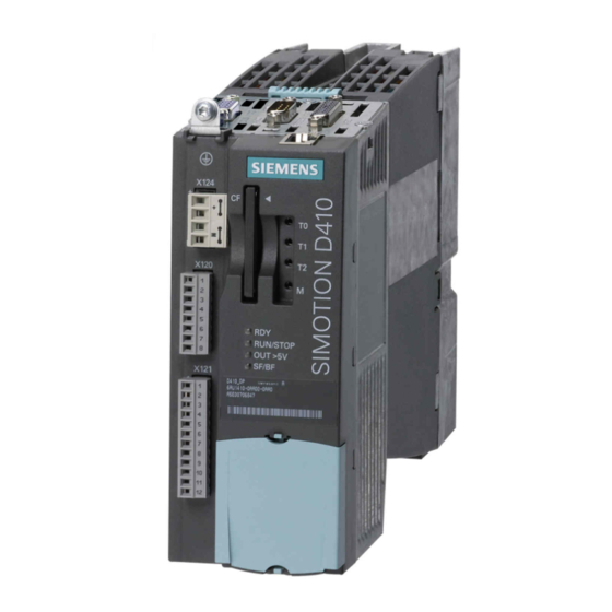
Description 1.3 SIMOTION D410 DP display SIMOTION D410 DP display View The following figure shows SIMOTION D410 DP with the interfaces and front elements. Figure 1-2 Location of interfaces and front elements in SIMOTION D410 DP Note The label underneath the mode selector lists the switch settings for the operating states of the SIMOTION D410. - Page 22 Description 1.3 SIMOTION D410 DP display Interfaces The SIMOTION D410 DP interfaces are described in the following tables. Table 1- 5 SIMOTION D410 interfaces Interface Description Digital inputs/outputs 12-pin Mini Combicon: X121 4 digital inputs: for connecting switches or proximity sensors •...
- Page 23 Description 1.3 SIMOTION D410 DP display The type plate below is located on the front of the SIMOTION D410 DP. Figure 1-4 SIMOTION D410 DP nameplate (example) Note The contents of the individual nameplate fields on the current module may differ from those described in this Manual (e.g., updated product status, space for approvals and identifications, etc.).
-
Page 24: Simotion D410 Pn Display
Description 1.4 SIMOTION D410 PN display SIMOTION D410 PN display View The following figure shows SIMOTION D410 PN with the interfaces and front elements. Figure 1-5 Location of interfaces and front elements in SIMOTION D410 PN SIMOTION D410 Commissioning Manual, 02/2012... - Page 25 Description 1.4 SIMOTION D410 PN display Interfaces The SIMOTION D410 PN interfaces are described in the following tables. Table 1- 6 SIMOTION D410 interfaces Interface Description Digital inputs/outputs 12-pin Mini Combicon: X121 4 digital inputs: for connecting switches and proximity sensors •...
-
Page 26: The Compactflash Card
Description 1.5 The CompactFlash card The following nameplate includes the MAC address of the PROFINET interface (ports X200 and X201) and is located on the front side of the module. Figure 1-7 SIMOTION PN nameplate (example) Note The contents of the individual nameplate fields on the current module may differ from those described in this Manual (e.g., updated product status, space for approvals and identifications, etc.). -
Page 27: Licensing
Description 1.6 Licensing Pre-installed runtime licenses For versions V4.1 SP1 HF6 and higher, pre-installed licenses are printed on the type plate of the CompactFlash Card as a Z option underneath the order number. Example with Z option for a SIMOTION IT Virtual Machine license + 2 TControl licenses: 6AU1400-2PA00-0AA0-Z Z=J00+T02 A maximum of 7 different Z options are printed on the type plate of the CompactFlash Card. -
Page 28: Safety Information
Description 1.7 Safety information Safety information Observe the following safety information when working with SIMOTION D410 and its components! CAUTION The CompactFlash Card may only be inserted or removed when the SIMOTION D410 is de-energized The SIMOTION D410 is in a de-energized state when all the LEDs are OFF. CAUTION The 50 mm clearances above and below the components must be observed. -
Page 29: Commissioning (Hardware)
Commissioning (hardware) Prerequisites for commissioning Prerequisites Prerequisites for commissioning the SIMOTION D410: ● You have completed installation and the wiring of your system with SIMOTION D410. ● A programming device / PC is available. Connecting a programming device / PC to SIMOTION D410 You can interconnect the programming device / PC: ●... -
Page 30: Inserting The Compact Flash Card
Commissioning (hardware) 2.2 Inserting the Compact Flash card Inserting the Compact Flash card Properties of the CF card The CF card is mandatory for operation of SIMOTION D410. The SIMOTION kernel and the drive control software (SINAMICS firmware) are installed on the CF card. The CompactFlash card must be inserted when you start up SIMOTION D410 in order to load the SIMOTION kernel. -
Page 31: Switching On The Power Supply
Commissioning (hardware) 2.3 Switching on the power supply Switching on the power supply Checking the system Check the system installation and wiring once again before you switch it on. Observe the safety-relevant items of the following checklist: ● Have you observed all ESD measures when handling the components? ●... -
Page 32: Reset Button
Commissioning (hardware) 2.4 RESET button 3. All DRIVE-CLiQ connections (with SINAMICS S120 Power Module PM340, for example) are identified automatically. 4. Startup of SIMOTION D410 is completed as soon as its RDY LED is lit in green color and the RUN/STOP LED is lit in yellow or green color. The SIMOTION D410 is ready for configuring after successful completion of the startup. -
Page 33: User Memory Concept
Commissioning (hardware) 2.5 User memory concept User memory concept 2.5.1 SIMOTION D410 memory model The following figure provides an overview of the SIMOTION D410 memory model. Figure 2-2 SIMOTION D410 memory model As a result, the SIMOTION Kernel (D410 firmware) contains the functions required for virtually all applications, and essentially acts as a PLC featuring an IEC 61131-3-compliant command set as well as system functions for controlling various components, such as inputs and outputs. -
Page 34: Properties Of The User Memories
Commissioning (hardware) 2.5 User memory concept See also Properties of the user memories (Page 34) Operator actions and their impact on user memory (Page 37) 2.5.2 Properties of the user memories Non-volatile data Non-volatile data is used with the objective of retaining user- and system-relevant data when SIMOTION D410 is in de-energized state. - Page 35 Commissioning (hardware) 2.5 User memory concept Table 2- 2 Non-volatile data and real-time clock properties Properties Non-volatile data Real-time clock Location Non-volatile data resides in the The real-time clock is backed up using FRAM of SIMOTION D410. SuperCap. Backup battery Backup time Unlimited At least 5 days...
- Page 36 Commissioning (hardware) 2.5 User memory concept ● These data is lost after the SIMOTION D410 is shut down. ● The "volatile SIMOTION data" area contains the following data: – SIMOTION kernel – Technology packages (TP) – User data (programs, configuration data, parameters) Figure 2-3 Configuration data and system variables on volatile memory SIMOTION...
-
Page 37: Operator Actions And Their Impact On User Memory
Commissioning (hardware) 2.5 User memory concept 2.5.3 Operator actions and their impact on user memory The operator actions and their effects on the user memory are described below. These operator actions are marked with arrows in the following displays: ● Figure 2-2 SIMOTION D410 memory model (Page 33) ●... - Page 38 Commissioning (hardware) 2.5 User memory concept To save the configuration data changed online to the offline project, you must first transfer the content of the current RAM to the RAM using the menu command "Target system" > "Copy current data to RAM". Once you have done this, the configuration in SCOUT will no longer be consistent with the configuration in the target device, as a consistency check is performed on the RAM data.
- Page 39 Commissioning (hardware) 2.5 User memory concept Backing up non-volatile SIMOTION data You have the following options for backing up non-volatile SIMOTION data on the CompactFlash Card: ● In the user program With the _savePersistentMemoryData system function, the user program can back up the non-volatile SIMOTION data content to the CompactFlash Card.
- Page 40 Commissioning (hardware) 2.5 User memory concept Reloading non-volatile SIMOTION data SIMOTION data backed up on a CompactFlash Card with _savePersistentMemoryData is restored in the following cases: 1. after replacing a module, refer to section Replacing modules (spare part scenario) (Page 165). 2.
- Page 41 Commissioning (hardware) 2.5 User memory concept Evaluating via the diagnostics buffer When they are issued, the following messages are entered once in the diagnostics buffer: Table 2- 4 Messages of the diagnostics buffer Entry Meaning Remedy Non-volatile data loaded from file Non-volatile SIMOTION data has been successfully restored from the backup (Persistent Data File Loading done)
- Page 42 Commissioning (hardware) 2.5 User memory concept Table 2- 6 State of the non-volatile SIMOTION data after powering up (persistentDataState system variable) Status Meaning FROM_RAM (1) Non-volatile SIMOTION data in the SIMOTION device is used FROM_FILE (2) Non-volatile SIMOTION data is restored from the backup file FROM_BACKUP (3) Non-volatile SIMOTION data is restored from the backup copy of the backup file...
- Page 43 Commissioning (hardware) 2.5 User memory concept Requirement/presence of the battery (from V4.2) System variables can be used to evaluate: ● Whether a battery is required for the operation of the device (or not) ● Whether a battery is present (or not) Table 2- 7 System variable batterynecessary/batteryexisting System variable...
- Page 44 Commissioning (hardware) 2.5 User memory concept Requirement/presence of a fan (from V4.2) System variables can be used to evaluate: ● Whether a fan is required for the operation of the device (or not) ● Whether a fan is available (or not) Table 2- 8 System variable fannecessary/fanexisting System variable on the...
-
Page 45: Parameter Assignment / Addressing
Parameter assignment / addressing Software requirements SIMOTION SCOUT Engineering System The SIMOTION SCOUT Engineering System must be installed on your programming device / PC in order to commission the SIMOTION D410. Please note the information on the latest "SIMOTION SCOUT" DVD. For information on how to install SIMOTION SCOUT on your programming device / PC, refer SIMOTION SCOUT to the... - Page 46 Parameter assignment / addressing 3.2 Creating a project and configuring the communication 3. In the project navigator, double-click "Insert SIMOTION device". The "Insert SIMOTION device" dialog box is opened: Figure 3-1 Inserting a SIMOTION device 4. In the "Insert SIMOTION device" dialog box, select the device, its version and the SIMOTION version.
- Page 47 Please note that separate SIMOTION D firmware is available for PROFINET versions V2.1 and V2.2. The required firmware can be found on the SCOUT DVD, as well as at Internet address (http://support.automation.siemens.com/WW/view/en/31045047). Mixed operation of the PROFINET V2.1 and V2.2 synchronization processes is not possible in a network.
-
Page 48: Configuring The Properties Of The Profinet Interface
Parameter assignment / addressing 3.2 Creating a project and configuring the communication 3.2.2 Configuring the properties of the PROFINET interface Procedure After you have closed the "Insert SIMOTION device" dialog box by pressing "OK", the "Properties - Ethernet interface" dialog box is opened on a D410 PN. If you are using the PROFINET interface, set the interface properties in the "Properties - Ethernet interface"... -
Page 49: Configuring The Profibus Pg/Pc Interface (Only For D410 Dp)
Parameter assignment / addressing 3.2 Creating a project and configuring the communication 3.2.3 Configuring the PROFIBUS PG/PC interface (only for D410 DP) Prerequisites The following requirements must be satisfied in order to configure the PG/PC interface: ● You have completed the "Insert SIMOTION device" dialog box with "OK". ●... -
Page 50: Configuring The Ethernet Pg/Pc Interface (Only For D410 Pn)
– "Insert device and connect to target system" > "Go online/offline" ● On the Internet at Internet address (http://support.automation.siemens.com/WW/view/en/22016709) ● In SIMOTION Utilities & Applications, FAQ "Online connections to SIMOTION devices". SIMOTION Utilities & Applications is part of the scope of delivery of SIMOTION SCOUT. - Page 51 Parameter assignment / addressing 3.2 Creating a project and configuring the communication Procedure 1. In the "Interface selection - D410" dialog box, select the entry "Ethernet PNxIO (X200)" as the interface selection. Figure 3-4 Selecting the Ethernet interface 2. Select the interface parameter assignment that you would like to use to go online, and confirm with "OK".
-
Page 52: Representation In Hw Config
– "Insert device and connect to target system" > "Go online/offline" ● On the Internet at Internet address (http://support.automation.siemens.com/WW/view/en/22016709) ● In SIMOTION Utilities & Applications, FAQ "Online connections to SIMOTION devices" SIMOTION Utilities & Applications is part of the scope of delivery of SIMOTION SCOUT. -
Page 53: Configuring The Profibus Dp Interface (Only D410 Dp)
Parameter assignment / addressing 3.3 Configuring the PROFIBUS DP interface (only D410 DP) Configuring the PROFIBUS DP interface (only D410 DP) 3.3.1 General information about PROFIBUS DP communication Definition of PROFIBUS DP PROFIBUS DP is an international, open field bus standard specified in the European field bus Standard EN 50170 Part 2. -
Page 54: Assignment Of The Profibus Addresses In Hw Config
Parameter assignment / addressing 3.3 Configuring the PROFIBUS DP interface (only D410 DP) 3.3.2 Assignment of the PROFIBUS addresses in HW Config Assigning PROFIBUS addresses Assign a PROFIBUS address to all devices before you start networking these in order to enable intercommunication. -
Page 55: Operating Simotion D410 On Profibus Dp
Parameter assignment / addressing 3.3 Configuring the PROFIBUS DP interface (only D410 DP) 3.3.3 Operating SIMOTION D410 on PROFIBUS DP. PROFIBUS DP interface (X21) SIMOTION D410 provides an interface for connecting to PROFIBUS DP. The interface supports transmission rates up to 12 Mbit/s. The X21 interface can be operated as a: ●... -
Page 56: Setting The Dp Cycle And System Cycle Clocks
Parameter assignment / addressing 3.3 Configuring the PROFIBUS DP interface (only D410 DP) 4. Click "New" to open the "Properties - New PROFIBUS Subnet" dialog box. 5. Name the new subnet, and then enter its properties in the "Network settings" tab, for example, the transmission rate. -
Page 57: Rules For Simotion D410 Dp
Parameter assignment / addressing 3.3 Configuring the PROFIBUS DP interface (only D410 DP) The PROFIBUS DP interface can also be operated in isochronous slave mode. In this constellation system clocks are based on the clock signals received at the slave interface. A substitute clock of a duration equivalent to the configured clock is generated internally if the isochronous slave interface has not received a clock signal. -
Page 58: Operating The Profibus Interface (X21) As An Mpi Interface
Parameter assignment / addressing 3.3 Configuring the PROFIBUS DP interface (only D410 DP) Rules for SIMOTION D410 DP The general rule for SIMOTION D410 specifies that the DP cycle (D410 DP) forms the basic clock of the cycle system. All cycles longer than this basic clock must be an integer multiple of the basic clock. -
Page 59: Configuring Profinet (Only For D410 Pn)
Parameter assignment / addressing 3.4 Configuring PROFINET (only for D410 PN) The following list provides examples of when using MPI (Multi Point Interface) may prove effective: ● If a PC/programming device is being used with an MPI interface ● If an OP/TP only has an MPI interface (newer devices have PROFIBUS or PROFINET interfaces) ●... -
Page 60: Operating Simotion D410 Pn On Profinet
Parameter assignment / addressing 3.4 Configuring PROFINET (only for D410 PN) 3.4.2 Operating SIMOTION D410 PN on PROFINET PROFINET interface (port X200, X201) SIMOTION D410 PN provides a dual-port PROFINET interface (X200 and X201). The interface supports transmission rates as high as 100 Mbit/s. It can also be operated isochronous and equidistant. - Page 61 Parameter assignment / addressing 3.4 Configuring PROFINET (only for D410 PN) 11. Click the "Update" button in the "Reachable Nodes" window. The SIMOTION D410 device is now displayed as "Geraet_01" with the type designation of the device and the assigned IP address. 12.
- Page 62 Parameter assignment / addressing 3.4 Configuring PROFINET (only for D410 PN) Changing the IP address, device name, network gateway Set the IP address, the subnet mask and, if necessary, the data for a gateway (router address) in order to enable communication over PROFINET with SIMOTION D410. If you want to change the properties in the PROFINET subnet, you can change them using the "Reachable nodes"...
-
Page 63: Setting The Send Cycles And System Clocks
Parameter assignment / addressing 3.4 Configuring PROFINET (only for D410 PN) 3.4.3 Setting the send cycles and system clocks Prerequisite The SIMOTION system clocks (servo/IPO/IPO2) are based on the SINAMICS Integrated DP cycle or the PROFINET send cycle, depending on the PROFINET real-time class and the type of data transfer. -
Page 64: Rules For Simotion D410 Pn
Parameter assignment / addressing 3.4 Configuring PROFINET (only for D410 PN) Setting the send cycle in HW Config The PROFINET send cycle always forms the basis for the SIMOTION cycles if the "IRT communication" real-time class is set and data are being transferred. Set the send cycle in the "Domain Management"... - Page 65 Parameter assignment / addressing 3.4 Configuring PROFINET (only for D410 PN) Rules for SIMOTION D410 PN As a general rule for SIMOTION D410, the send cycle (D410 PN) forms the basic clock of the task system. All cycles longer than this basic clock must be an integer multiple of the basic clock.
- Page 66 Parameter assignment / addressing 3.4 Configuring PROFINET (only for D410 PN) SIMOTION D410 Commissioning Manual, 02/2012...
-
Page 67: Commissioning (Software)
Commissioning (software) Overview of commissioning Prerequisites The prerequisites for commissioning the SIMOTION D410 are as follows: ● The system has been connected and wired. ● The SIMOTION D410 is switched on and started up (STOP operating mode). ● SIMOTION SCOUT (with integrated STARTER) has been installed and started on the PG / PC. - Page 68 Commissioning (software) 4.1 Overview of commissioning Thus, other than symbolic assignment, no more configuration settings are required for communication. Since addresses no longer have to be configured, the connection is maintained even if addresses change. Note During the configuration of drive objects (DO drive, DO encoder, etc.) as well as in the Message Frame Configuration dialog box (refer to section Message frame configuration (Page 115)), you can deactivate Automatic message frame configuration and Automatic message frame adaptation.
- Page 69 Commissioning (software) 4.1 Overview of commissioning Activating symbolic assignment retrospectively Symbolic assignment significantly simplifies the configuration of the technological relationships including the communication between controller and drive. The designation of the symbolic assignments in plain text is also an advantage for maintenance of projects. Symbolic assignment is therefore recommended and is activated automatically for new projects from V4.2.
- Page 70 The documentation of older SIMOTION versions can be found on the Internet at the following Internet address (http://support.automation.siemens.com/WW/view/en/40211807) . For further information on the configuration of the TO axis and TO external encoder, refer to TO Axis Electric/Hydraulic, External Encoder Function Manual.
-
Page 71: Procedure When Commissioning
Commissioning (software) 4.1 Overview of commissioning 4.1.2 Procedure when commissioning Commissioning steps This chapter describes the steps in configuring the plant and testing the configured stand- alone drive and axis. The steps in commissioning are listed below in the order as recommended: 1. -
Page 72: Important Functions For The Project Handling During Commissioning
Commissioning (software) 4.1 Overview of commissioning 4.1.3 Important functions for the project handling during commissioning The following functions are very important for the project handling and commissioning: Table 4- 2 Functions with their symbols Save project and compile changes The entire project is saved and the project data (e.g. programs) compiled into an executable code. -
Page 73: Configuring The System In Offline Mode
Commissioning (software) 4.2 Configuring the system in offline mode Configuring the system in offline mode 4.2.1 Overview Introduction In the case of offline configuration, the project is created while not all of the hardware components (in particular drives) are available. In this way, a SIMOTION project can be developed in the office environment to the point that there is a basic project specification, including the program. -
Page 74: Accessing The Drive Wizard
Commissioning (software) 4.2 Configuring the system in offline mode 4.2.2 Accessing the drive wizard Integrated drive SIMOTION D410 features an integrated SINAMICS S120 drive (control unit) which is automatically included when you insert the SIMOTION D410 in the Project Navigator. The integrated drive must be operated in equidistant, isochronous mode using PROFIdrive- compliant message frame types. - Page 75 Commissioning (software) 4.2 Configuring the system in offline mode 1. Enter a drive name in the "Drive Properties" dialog box and select the drive type (servo or vector). Figure 4-1 Drive properties 2. You can select the function modules and the control mode in the "Open-loop Control Structure"...
- Page 76 Commissioning (software) 4.2 Configuring the system in offline mode 3. In the "Power Unit" dialog, use the order number to select your power unit from the list. Figure 4-3 Selecting a power unit 4. In the "Power unit supplementary data", select the component added to the power unit. The selection of the component depends on the construction type: –...
- Page 77 Commissioning (software) 4.2 Configuring the system in offline mode 5. In the next dialog, select the motor and, where applicable, the motor type: – Either by selecting a standard motor from the list – Or by entering the motor data, –...
- Page 78 Commissioning (software) 4.2 Configuring the system in offline mode 6. Select a motor holding brake (if installed). Figure 4-6 Selecting a motor holding brake 7. If you are using a motor that is not equipped with a DRIVE-CLiQ interface, select the encoder order number in the "Encoder Selection via Motor Order Number"...
- Page 79 Commissioning (software) 4.2 Configuring the system in offline mode Figure 4-8 Selecting a motor encoder (2) Note If required, you can configure a second or third encoder in the "Encoder" dialog. You can transmit a maximum of 2 encoder values to SIMOTION via the axis message frame. In the case of motors with a DRIVE-CLiQ interface, the motor encoder is identified automatically.
- Page 80 Commissioning (software) 4.2 Configuring the system in offline mode Figure 4-9 Configuring the process data exchange SIMOTION D410 Commissioning Manual, 02/2012...
-
Page 81: Downloading The Project To The Target System
Commissioning (software) 4.2 Configuring the system in offline mode A "Summary" dialog box opens with a listing of all settings after you completed all settings in the Drive Wizard. You can now choose to activate your settings by clicking "Finish", or to return to the component configuration for further editing. -
Page 82: Loading A Project Created Offline To The Compactflash Card
Commissioning (software) 4.2 Configuring the system in offline mode Procedure 1. Save and compile the project. 2. Go online to SIMOTION D410. 3. To load the project, perform "Download project to target system". The data must also be saved on the CompactFlash Card to ensure that the project is retained in the event of a power failure. -
Page 83: Downloading The Project Incl. Sources And Additional Data
Commissioning (software) 4.2 Configuring the system in offline mode 8. Confirm your entries with "OK". The data will be written to the CompactFlash Card. 9. Remove the CF card and insert it in the D410 slot. 10. Switch on the D410. The D410 starts with the downloaded project. Note The components' firmware is automatically updated, depending on the FW version on the SINAMICS components and on the CompactFlash Card. -
Page 84: Archiving A Project On The Compactflash Card (Zip File)
Commissioning (software) 4.2 Configuring the system in offline mode You have the following options in terms of re-establishing consistency: ● In the object comparison, it is possible to establish consistency in sources and technology objects on an object-granular basis. ● Consistency can be established for the entire control unit by loading from the CompactFlash Card via "Target system"... -
Page 85: Performing An Online Configuration
Commissioning (software) 4.3 Performing an online configuration Performing an online configuration 4.3.1 Overview Introduction You can configure the plant in online mode after having completed its wiring. You can use the "Automatic configuration" function to load the SINAMICS components connected via DRIVE-CLiQ to your programming device/PC. -
Page 86: Establishing The Online Connection
Commissioning (software) 4.3 Performing an online configuration 4.3.2 Establishing the online connection The procedure for an initial commissioning follows. To perform an online configuration, you must establish an online connection to the SIMOTION D410. In this case, no connection can yet be established to SINAMICS Integrated. - Page 87 Commissioning (software) 4.3 Performing an online configuration Procedure 1. Open the "Automatic Configuration" dialog box by selecting the "SINAMICS_Integrated > Automatic configuration" command in the Project Navigator. Figure 4-11 Starting automatic configuration 2. Click the "Configure" button. 3. If the drive unit is not in the "Initial commissioning" state, the factory settings are restored after acknowledging a prompt.
- Page 88 Commissioning (software) 4.3 Performing an online configuration 6. Click "Create" to start the automatic configuration. The configuration data is uploaded (Load to PG) automatically as soon as automatic configuration is completed. Note The components' firmware is automatically updated, depending on the FW version on the CompactFlash Card and on the SINAMICS components.
-
Page 89: Editing Sinamics Components
Commissioning (software) 4.3 Performing an online configuration Result The DRIVE-CLiQ components loaded to the user project by means of automatic configuration are displayed in the project navigator. Figure 4-13 Project Navigator with the downloaded DRIVE-CLiQ components You must then ● If required, reconfigure SINAMICS components (e.g. components without a DRIVE-CLiQ interface, such as an encoder connected to the onboard encoder interface). -
Page 90: Download The Project To Simotion D410
Commissioning (software) 4.3 Performing an online configuration Procedure Now go ahead and adapt your components to suit the application. Run through the wizard for all the DRIVE-CLiQ components to be adapted and perform the required reconfigurations. This procedure corresponds to the description in section Configuring the system in offline mode (Page 73). -
Page 91: Additional Information On Configuring The Sinamics Integrated
Commissioning (software) 4.4 Additional information on configuring the SINAMICS Integrated Additional information on configuring the SINAMICS Integrated 4.4.1 Setting DP Slave properties Settings in HW Config Depending on the cycle clock ratios (bus cycle, servo cycle) and the drive used, it may be necessary to adapt the properties of the DP slave (SINAMICS Integrated) on the PROFIBUS Integrated. - Page 92 Commissioning (software) 4.4 Additional information on configuring the SINAMICS Integrated ● Changing the DP cycle (T Depending on the requirements in terms of the quantity structures and response times, SIMOTION SCOUT Basic the DP cycle may need to be changed. (Also refer to the Functions Function Manual).
-
Page 93: Using Vector Drives
Commissioning (software) 4.4 Additional information on configuring the SINAMICS Integrated 4.4.2 Using vector drives Changes need to be made in HW Config when SINAMICS vector drives are used. This means, for example, that the T time and the minimum DP cycle for drives in chassis format depend on the type of device used. -
Page 94: Set Time Of Day
Commissioning (software) 4.4 Additional information on configuring the SINAMICS Integrated Note Vector drives in chassis format can also be operated with a current controller sampling time of 400 µs (among other settings). In a SIMOTION context, the following should be considered: ●... - Page 95 Commissioning (software) 4.4 Additional information on configuring the SINAMICS Integrated SINAMICS system runtime (operating hours counter) For SINAMICS S120 control units and the SINAMICS Integrated on a SIMOTION D410, faults and warnings are "time-stamped" on the basis of the system runtime. By default, events are recorded in terms of operating hours rather than in terms of a particular time of day or date.
- Page 96 Commissioning (software) 4.4 Additional information on configuring the SINAMICS Integrated Synchronizing the SINAMICS clock Proceed as follows to convert the SINAMICS clock to UTC format and to synchronize this with the SIMOTION clock: 1. In the project navigator, call the context menu of the SIMOTION D410. 2.
-
Page 97: Sinamics Diagnostic Buffer
Commissioning (software) 4.4 Additional information on configuring the SINAMICS Integrated Note For SIMOTION versions < V4.2, the time synchronization must be performed "applicatively". You can find an example of a program in SIMOTION Utilities & Applications. If "applicative time synchronization" is used for SIMOTION versions ≥ V4.2, the time synchronization must be deactivated in the "Settings on the device"... -
Page 98: Acyclic Communication With The Drive
Commissioning (software) 4.4 Additional information on configuring the SINAMICS Integrated Procedure To do this, select the SINAMICS Integrated in the project tree, followed by "Target System" > "Device Diagnostics". In addition, the SINAMICS diagnostic buffer entries are displayed in the D410 device diagnostics. - Page 99 Commissioning (software) 4.4 Additional information on configuring the SINAMICS Integrated Additional references SIMOTION Additional information on how to use DP V1 services can be found in the Communication System Manual. SIMOTION Utilities & Applications also has a DP V1 library with functions that are capable of undertaking coordination tasks commonly associated with acyclic communication.
-
Page 100: Control Properties And Performance Features
Commissioning (software) 4.4 Additional information on configuring the SINAMICS Integrated 4.4.6 Control properties and performance features With a few exceptions, the integrated drive control of the SIMOTION D410 has the same control properties and performance features as the SINAMICS S120 CU310 Control Unit. However, the following points must be particularly observed: ●... -
Page 101: Testing The Configured Drive Using The Drive Control Panel
Commissioning (software) 4.5 Testing the configured drive using the drive control panel Table 4- 4 Influence of the current controller cycle clock on the dead time compensation The current controller cycle The current controller cycle clock does clock has no effect on the have an effect on the function function Cam outputs... - Page 102 Commissioning (software) 4.5 Testing the configured drive using the drive control panel Prerequisites ● The project has been downloaded to the target system. ● SIMOTION SCOUT is in online mode. ● The drive is not in use by a current project in RUN mode. WARNING Make sure that the drive test does not pose any risk to persons.
-
Page 103: Creating And Testing An Axis
Commissioning (software) 4.6 Creating and testing an axis 4. Read the notes and confirm these with "Accept". 5. Activate the "Enables" checkbox to enable the drive. All enables are now set with the exception of ON/OFF1. 6. Enter your setpoint in the input field and shift the scaling to 0% as safety setting. Figure 4-18 Entering the setpoint 7. -
Page 104: Creating An Axis With The Axis Wizard
Commissioning (software) 4.6 Creating and testing an axis 3. Complete your SIMOTION application, for example, by creating axis functions and SIMOTION execution programs. 4. Compile the project and download it to SIMOTION D410. Note Note that only one real axis can be used on a SIMOTION D410. 4.6.2 Creating an axis with the axis wizard Overview... - Page 105 Commissioning (software) 4.6 Creating and testing an axis Inserting an axis 1. In the project navigator, double-click the entry "Axis" > "Insert Axis". This will access the axis wizard. Set the required technology and then click "OK". Figure 4-19 Inserting an axis SIMOTION D410 Commissioning Manual, 02/2012...
- Page 106 Commissioning (software) 4.6 Creating and testing an axis 2. Set an axis type and, if required, configure the units. Figure 4-20 Defining the axis type SIMOTION D410 Commissioning Manual, 02/2012...
- Page 107 Commissioning (software) 4.6 Creating and testing an axis 3. Create a new drive or make the assignment to an existing drive. Figure 4-21 Assigning a drive The following setting options are available for the drive assignment: ● Assign drive Assigning a previously configured drive ●...
- Page 108 Commissioning (software) 4.6 Creating and testing an axis ● Create drive From the assignment dialog box, a new drive can be created on an existing drive unit (e.g. SINAMICS Integrated) and assigned to the axis. This allows the axis, including the drive, to be created in one operation.
- Page 109 Commissioning (software) 4.6 Creating and testing an axis 1. Run through the wizard and enter the settings of your system. The required axis message frame as well as the addresses used are automatically determined by the engineering system. The message frame is also extended and interconnections in the drive created automatically depending on the selected TO technology (e.g.
- Page 110 Commissioning (software) 4.6 Creating and testing an axis Encoder assignment With a position axis, encoder 1 is also created at the Axis TO (motor encoder) and automatically assigned to the first encoder on the drive. If encoder 2 (direct encoder) is created at the TO axis, it is assigned to the second encoder of the drive control.
-
Page 111: Testing An Axis With The Axis Control Panel
Commissioning (software) 4.6 Creating and testing an axis I/O signals at the TO axis For the assignment of I/O signals on the TO axis (e.g. the inputs for the homing output cam or hardware limit switches) call the assignment dialog box from the parameterization dialog boxes or from the address list (view all addresses) by clicking the button. - Page 112 Commissioning (software) 4.6 Creating and testing an axis Axis test 1. Open the "AXES" folder in the Project Navigator and click the "Control panel" entry below the axis (for example, Axis_1). The axis control panel is displayed. Figure 4-23 Axis control panel 2.
- Page 113 Commissioning (software) 4.6 Creating and testing an axis 4. The "Assume Control Priority" dialog box opens. Figure 4-24 Assuming control priority 5. Read the notes and confirm these with "Accept". 6. To enable the axis, click "Set/reset enables". Confirm the "Switch Axis Enable" dialog box with "OK". 7.
-
Page 114: Setting Up Addresses And Message Frames
Commissioning (software) 4.7 Setting up addresses and message frames Setting up addresses and message frames Overview After all SINAMICS components have been configured, addresses must be determined for the process data exchange between the drive and the controller. This procedure depends on whether symbolic assignments are used. ●... -
Page 115: Message Frame Configuration
Commissioning (software) 4.7 Setting up addresses and message frames 4.7.2 Message frame configuration Prerequisite You have configured the drive unit. On the basis of this configuration, one or more of the following actions should be performed: ● The automatic PROFIdrive message frame setting for a drive object should be activated/deactivated ●... - Page 116 Commissioning (software) 4.7 Setting up addresses and message frames Figure 4-25 Message frame configuration SIMOTION D410 Commissioning Manual, 02/2012...
- Page 117 Commissioning (software) 4.7 Setting up addresses and message frames Table 4- 5 Explanation of the figure Meaning ① Selection of a message frame The drive message frames (message frames 1 ... 6 and message frame 1xx) are defined in accordance with the •...
-
Page 118: Integrating Additional Encoders (Optional)
Commissioning (software) 4.8 Integrating additional encoders (optional) Note If symbolic assignment is deactivated, the following applies: If the message frames for drive objects (drives, terminal modules, etc.) change, you must set up the addresses again. The addresses are not updated automatically. Message frame status The icons in the status column show the following information: The message frame differs from the configuration in HW Config. -
Page 119: Configuring Additional Encoders On The Drive
Commissioning (software) 4.8 Integrating additional encoders (optional) Configuring additional encoders The second encoder can be used at SIMOTION D410, for example, as: ● A machine encoder (second encoder = direct measuring system) A direct measuring system measures the technological parameter directly, i.e. without the interference of influences such as torsion, backlash, slip, etc. -
Page 120: Connecting Additional Encoders Via Profibus/Profinet
Commissioning (software) 4.8 Integrating additional encoders (optional) Figure 4-26 Configuration of a second encoder on the drive 4.8.3 Connecting additional encoders via PROFIBUS/PROFINET Additional encoders for encoder integration can also be connected via PROFIBUS or PROFINET. The following options are available: ●... -
Page 121: Symbolic Assignment Of I/O Variables (Profidrive Message Frame / Drive Parameters)
Commissioning (software) 4.9 Symbolic assignment of I/O variables (PROFIdrive message frame / drive parameters) Symbolic assignment of I/O variables (PROFIdrive message frame / drive parameters) 4.9.1 Assignment to the PROFIdrive message frame of the TO axis I/O variables which you require for purposes such as display and diagnostics can be assigned from the address list to individual components (status word, for example) via the assignment dialog of the PROFIdrive message frame. - Page 122 Commissioning (software) 4.9 Symbolic assignment of I/O variables (PROFIdrive message frame / drive parameters) Procedure 1. Open the assignment dialog box from the address list (view of all addresses). The assignment dialog opens with the corresponding assignment partners. 2. Click the button in the parameter selection line to open the parameter list.
- Page 123 Commissioning (software) 4.9 Symbolic assignment of I/O variables (PROFIdrive message frame / drive parameters) 3. Select the desired signal source (e.g. DO drive). Then select the required parameter. Figure 4-29 Dialog box for the DO and parameter selection SIMOTION D410 Commissioning Manual, 02/2012...
- Page 124 Commissioning (software) 4.9 Symbolic assignment of I/O variables (PROFIdrive message frame / drive parameters) 4. Click "OK" to accept the selection. The desired SINAMICS parameter is assigned to the I/O variable in the interconnection dialog box. Figure 4-30 Assigned drive parameters 5.
-
Page 125: Configuring Drive-Related I/Os (With Symbolic Assignment)
Commissioning (software) 4.10 Configuring drive-related I/Os (with symbolic assignment) 4.10 Configuring drive-related I/Os (with symbolic assignment) Overview SIMOTION D410 as well as the SINAMICS S110/S120 control units and additional components (TB30, TMs) have I/Os that can be used by the drive unit and by SIMOTION. So that I/Os, which were originally assigned to SINAMICS can be used by SIMOTION they must be interconnected to a message frame. - Page 126 Commissioning (software) 4.10 Configuring drive-related I/Os (with symbolic assignment) Procedure The configuration of the I/Os is divided into two basic steps: 1. Configuring I/O terminals (Page 127) The functionality of an I/O channel is configured (e.g. configuration of a DI/DO as digital output) 2.
-
Page 127: Configuring I/O Terminals
Commissioning (software) 4.10 Configuring drive-related I/Os (with symbolic assignment) 4.10.1 Configuring I/O terminals The following table provides an overview of the configuration options for the I/O terminals of various modules. Table 4- 7 Overview of the configuration of the I/O terminals Module Use of the I/Os by Configuration of the I/O terminals... -
Page 128: Configuration Of Simotion D410 I/Os (Terminal X121)
Commissioning (software) 4.10 Configuring drive-related I/Os (with symbolic assignment) The configuration of the I/O terminals is described in detail in the following: ● Configuration of SIMOTION D410 I/Os (terminal X121) (Page 128) ● Configuration of CU3xx/TB30/TMxx I/Os (Page 129) ● Configuring TMC I/O terminals (Page 129) 4.10.1.1 Configuration of SIMOTION D410 I/Os (terminal X121) The I/Os of terminal X121 are originally assigned to the drive unit. -
Page 129: Configuration Of Cu3Xx/Tb30/Tmxx I/Os
Commissioning (software) 4.11 Configuring technology objects and I/O variables 4.10.1.2 Configuration of CU3xx/TB30/TMxx I/Os The configuration is performed in a similar way as for the onboard I/Os X121 for the SIMOTION D410, i.e. the I/Os can be ● BICO-interconnected (use as drive I/O) ●... - Page 130 Commissioning (software) 4.11 Configuring technology objects and I/O variables The following measuring input types are available: Table 4- 8 Measuring input types Measuring input types Explanation Standard (global Compared with the drive-related local measuring inputs, global measuring measuring input) inputs have extended functionality and also support a symbolic configuration.
-
Page 131: Configuring Local Measuring Inputs
Commissioning (software) 4.11 Configuring technology objects and I/O variables Detailed information on the configuration of the TO measuring input can be found in the SIMOTION Output Cams and Measuring Inputs Function Manual. 4.11.2 Configuring local measuring inputs Local measuring inputs are drive-related measuring inputs. The configuration is performed via drive parameters. -
Page 132: Configuring Output Cams / Cam Tracks
Commissioning (software) 4.11 Configuring technology objects and I/O variables 4.11.3 Configuring output cams / cam tracks Overview The type of cam output must be selected during the configuration of the TO outputCam and TO camTrack. The following output types are possible: Table 4- 9 TO outputCam / TO camTrack output types Cam output on... - Page 133 Commissioning (software) 4.11 Configuring technology objects and I/O variables Procedure To achieve the best possible output cam resolution on the onboard I/Os of a SIMOTION D410, activate the output and select "Cam output to high-speed digital output (DO)". Then assign a hardware output. For this purpose, click ("assign") to open the assignment dialog box and select a free (i.e.
-
Page 134: Configuration Of I/Os (Variables / To Axis)
Commissioning (software) 4.11 Configuring technology objects and I/O variables 4.11.4 Configuration of I/Os (variables / TO axis) Overview There are two options for assigning I/O terminals to an I/O variable: ● Assignment via preferential link (e.g. DI_0 [DI 0, X121.1]) To do this, you must use the SIMOTION preferential link for the corresponding input/outputs of the SINAMICS DOs. -
Page 135: Creating A Dmc20/Dme20
Commissioning (software) 4.12 Creating a DMC20/DME20 Alternatively, you can assign a SIMOTION I/O channel when configuring the terminals (e.g. by selecting "DI (SIMOTION)", see section Configuration of SIMOTION D410 I/Os (terminal X121) (Page 128)). TO axis The symbolic assignment of I/Os is also supported by the TO axis (e.g. for a HW limit switch). -
Page 136: Hub Properties
Commissioning (software) 4.12 Creating a DMC20/DME20 4.12.1 Hub properties DRIVE-CLiQ hub characteristics The DMC20 and DME20 DRIVE-CLiQ hub modules are used to implement point-to-point distribution of a DRIVE-CLiQ line. With the DMC20/DME20, an axis grouping can be expanded with four DRIVE-CLiQ sockets for additional subgroups. ●... -
Page 137: Creating And Programming Tm41
Commissioning (software) 4.13 Creating and programming TM41 3. Double-click "Topology" to open the topology tree. The hub is saved to the component storage of the topology tree. 4. Drag-and-drop the hub to the required DRIVE-CLiQ interface. The components connected to the hub are displayed in the topology tree. The hub you inserted is displayed as icon at the "Topology"... -
Page 138: Configuring Tm41 At Sinamics Integrated
Commissioning (software) 4.14 Optimizing the drive and controller 4.13.2 Configuring TM41 at SINAMICS Integrated TM41 can be configured after you completed the configuration of SINAMICS Integrated. Proceed as follows: 1. Double-click "Insert InputIOutput Ccomponent" at "Input/output component" in the Project Navigator. -
Page 139: Automatic Speed Controller Setting
Commissioning (software) 4.14 Optimizing the drive and controller Procedure Automatic controller setting involves the following steps: 1. Setting the speed controller 2. Setting the position controller Note You can cancel automatic controller setting by pressing the SPACEBAR. • The step currently being executed is canceled. •... -
Page 140: Automatic Position Controller Setting
Commissioning (software) 4.14 Optimizing the drive and controller 7. Disable the drive by clicking the "Drive OFF" button. 8. Click "Give up control priority" to give up control priority of the PG/PC. 9. Save the online parameters. You can now transfer the parameters that you have automatically set to the project. Backing up parameters Proceed as follows to back up the parameters: 1. - Page 141 Commissioning (software) 4.14 Optimizing the drive and controller ● For operation without precontrol, the equivalent time constant of the position controller must be adjusted manually by the user (PostionTimeConstant = 1/Kv). ● Vibration on the load side is not taken into account for position controller setting. Procedure To perform automatic setting of the position controller, proceed as follows: 1.
-
Page 142: Measuring Functions, Trace, And Function Generator
Commissioning (software) 4.14 Optimizing the drive and controller 4.14.4 Measuring functions, trace, and function generator Drive optimization Drive optimization is part of commissioning and can be performed with SIMOTION SCOUT. CAUTION Controller optimization may only be performed by skilled personnel with knowledge of control engineering. -
Page 143: Manual Speed Controller Optimization
Commissioning (software) 4.14 Optimizing the drive and controller The following measuring functions are available: ● Setpoint jump at current controller ● Reference frequency response at current controller ● Setpoint jump at speed controller ● Interference jump at speed controller ● Reference frequency response at speed controller ●... - Page 144 Commissioning (software) 4.14 Optimizing the drive and controller 4. Select "Speed controller setpoint jump" as the measuring function. You can change the values in the following fields: "Settling time", "Amplitude", "Offset", "Ramp-up time", and "Measuring time". Four channels can be recorded. Depending on the measuring function, certain channels are preassigned.
- Page 145 Commissioning (software) 4.14 Optimizing the drive and controller 3. Click (Start measuring function) to start the measuring function. The axis is moved during measurement. For this reason, a safety message that allows the process to be canceled is displayed. 4. The signals recorded are represented on the "Timing Diagram" tab. Figure 4-38 Timing diagram before parameterization SIMOTION D410...
- Page 146 Commissioning (software) 4.14 Optimizing the drive and controller Adjusting the P-gain You can adjust the P-gain of the controller to optimize the transient response. 1. Under the corresponding drive (Servo_1, for example) in the project navigator, use the menu command "Open-Loop/Closed-Loop Control" > "Speed Controller" to display the "Speed Controller with Encoder"...
- Page 147 Commissioning (software) 4.14 Optimizing the drive and controller 3. For verification purposes, perform the measurement again. 4. With the modified parameters, the controller demonstrates a much better transient response. If necessary, you can continue changing the value until the transient response has reached its optimum level.
-
Page 148: Downloading And Saving Simotion User Data
Commissioning (software) 4.15 Downloading and saving SIMOTION user data 4.15 Downloading and saving SIMOTION user data Overview It is advisable to backup all SIMOTION user data (programs, configuration data, parameters) to the CompactFlash Card after having completed commissioning of SIMOTION D410. Downloading user data Use the "Target system"... - Page 149 Commissioning (software) 4.15 Downloading and saving SIMOTION user data Saving user data The "Copy RAM to ROM" function is used in SIMOTION SCOUT to save the following data from RAM to the CompactFlash Card: ● Technology packages and user data (units, configuration data, parameter assignments, task configuration) from the "volatile SIMOTION data"...
-
Page 150: Deleting Data
Commissioning (software) 4.16 Deleting data 4.16 Deleting data 4.16.1 Overview of data deletion You can define the scope of data to be deleted from SIMOTION D410 memory described in the "user memory concept". That is, you can choose to delete all data or only specific parts. You have the following options of deleting data from SIMOTION D410: ●... - Page 151 Commissioning (software) 4.16 Deleting data ● Retain TO (absolute encoder adjustment) ● Retain variables Retain variables are variables in the interface or implementation section of a UNIT that are declared with VAR_GLOBAL RETAIN, or global device variables with the RETAIN attribute.
- Page 152 Commissioning (software) 4.16 Deleting data Memory reset using the mode selector switch The mode selector switch function is implemented in SIMOTION D410 by means of a DIL switch (DIL = Dual-In-Line). Use this DIL switch (switch S1 - S3) to set the binary code for the mode of operation.
-
Page 153: Deleting User Data From The Compactflash Card
Commissioning (software) 4.16 Deleting data 4.16.3 Deleting user data from the CompactFlash Card Overview Deletion of the user data from the CompactFlash Card is necessary, for instance, if you wish to load another (new) project to the CompactFlash Card and therefore find it necessary to delete the existing user data for an "old project"... -
Page 154: Restoring The Default Settings Of Simotion D410
Commissioning (software) 4.16 Deleting data 4.16.5 Restoring the default settings of SIMOTION D410 Overview SIMOTION D410 is supplied with default parameters such as the transmission rate or PROFIBUS addresses. You can restore the default settings using the DIL switch. This deletes the following data: ●... -
Page 155: System Shutdown
Commissioning (software) 4.17 System shutdown 4.17 System shutdown All axes and system components must be in safe state before you shut down the system. You can set up this safe state by providing a separate motion task, for example. You can shut down the power supply after the system has reached a standstill state. Note You must observe the safety notices for SINAMICS components, which you can find in the corresponding SINAMICS manuals. - Page 156 Commissioning (software) 4.18 Configuring Safety Integrated functions Safety Integrated Extended Functions Safety Integrated Extended functions generally require a license. The following Safety Integrated Extended functions are available: Table 4- 11 Safety Integrated Extended Functions Function Abbreviatio Short description Safe Torque Off Safe torque off Safe Stop1 Drive-independent shutdown on the quick stop ramp and...
- Page 157 Commissioning (software) 4.18 Configuring Safety Integrated functions The Safety Integrated functions are implemented on an entirely electronic basis and, therefore, offer short response times in comparison to solutions with externally implemented monitoring functions. Note Although SIMOTION does not feature any safety-related functions, it provides support for SINAMICS drives that can perform safety-related functions.
- Page 158 ● The SIMOTION D410 DP is the master for F slave-to-slave communication, e.g. between a SIMATIC F CPU and a SINAMICS S120 CU. See also application example at the following Internet address (http://support.automation.siemens.com/WW/view/en/38701812). Note Control for the Safety Integrated functions cannot be routed through to the SINAMICS Integrated of the SIMOTION D410 in this configuration.
- Page 159 Commissioning (software) 4.18 Configuring Safety Integrated functions Cycle clock setting If PROFIsafe is used, a servo cycle clock > 2 ms can be set (e.g. setting: 4 ms). If the servo cycle clocks used are too small, the Control Unit will be over-utilized, which can lead to limitations in communication and the ability of engineering to respond (e.g.
- Page 160 Commissioning (software) 4.18 Configuring Safety Integrated functions SIMOTION D410 Commissioning Manual, 02/2012...
-
Page 161: Maintenance And Service
Maintenance and service Overview Introduction It is possible to distinguish between the following scenarios when replacing and updating components: ● Replacing modules (spare part scenario) – Spare parts replacement for SIMOTION D410 (Page 165) – Removing and replacing the SIMOTION D410 (Page 166) –... - Page 162 Maintenance and service 5.1 Overview Backup of the CF card data (Page 188) Update via CF card (Page 190) Upgrading SINAMICS (Page 191) Downloading the project to the target system (Page 192) The upgrade data is generated using the SCOUT function "Start device update tool" and then transferred to the SIMOTION D410 via Compact Flash Card or IT DIAG file.
- Page 163 Maintenance and service 5.1 Overview Overview The exact procedure when replacing or updating components depends on various factors. If a project is updated, the procedure depends on the scope of change of the versions. ● Change of the SIMOTION main version ●...
- Page 164 Maintenance and service 5.1 Overview Alternative: Load the project to the Compact Flash Card using a card reader See Software compatibility list (http://support.automation.siemens.com/WW/view/en/18857317). The versions of SINAMICS Integrated and Controller Extensions are upgraded automatically in the HW Config during device replacement The technology packages are automatically upgraded.
-
Page 165: Replacing Modules (Spare Part Scenario)
Maintenance and service 5.2 Replacing modules (spare part scenario) Replacing modules (spare part scenario) 5.2.1 Spare parts replacement for SIMOTION D410 Use of used modules If a used D410 is used for the module replacement, we recommend that the retained data be deleted from the used D410. -
Page 166: Removing And Replacing The Simotion D410
Maintenance and service 5.2 Replacing modules (spare part scenario) 5.2.2 Removing and replacing the SIMOTION D410 Overview You must replace the entire SIMOTION D410 module. WARNING Always shut down the load power supply before you replace the SIMOTION D410 module. You shut down power using the On/Off switch of the PS power supply module, for example. -
Page 167: Replacing Drive-Cliq Components
Maintenance and service 5.2 Replacing modules (spare part scenario) Replacing SIMOTION D410 modules without PC/programming device To enable a module replacement without a programming device/PC, you must back up the current non-volatile SIMOTION data to the CompactFlash Card. With the _savePersistentMemoryData system function, the user program can back up the contents of the non-volatile SIMOTION data to the CompactFlash Card. - Page 168 Maintenance and service 5.2 Replacing modules (spare part scenario) Procedure for installing a component 1. Mount the component and reconnect the supply voltage. 2. Reconnect the DRIVE-CLiQ cable at the same location (port). The cable must be the same length as the old one. 3.
-
Page 169: Replacing The Fan
Maintenance and service 5.2 Replacing modules (spare part scenario) Automatic upgrading/downgrading (FW update) When starting up, the system automatically upgrades or downgrades all DRIVE-CLiQ components to the version of the component firmware on the CompactFlash Card. Components that cannot be downgraded to the component firmware version on the CompactFlash Card (for example, old firmware on the CompactFlash Card and new components to which the old firmware cannot be loaded) retain their firmware version. - Page 170 Maintenance and service 5.2 Replacing modules (spare part scenario) Remedy: ● Check the supply air for the SIMOTION D410. – Does the control cabinet temperature fall within the permitted range? – Is natural convection possible? ● Check the fan for the SIMOTION D410. –...
-
Page 171: Replacing The Compactflash Card
● Replacing the CompactFlash Card (Page 193) ● Writing to a CompactFlash Card (Page 194) Detailed information about licensing can be found: SIMOTION SCOUT ● In the Configuration Manual ● as well as In the FAQ (http://support.automation.siemens.com/WW/view/en/36947932) SIMOTION D410 Commissioning Manual, 02/2012... -
Page 172: Adapting A Project (Upgrading The Project / Replacing The Simotion Controller)
Maintenance and service 5.3 Adapting a project (Upgrading the project / Replacing the SIMOTION controller) Adapting a project (Upgrading the project / Replacing the SIMOTION controller) 5.3.1 Overview Overview The project needs to be adapted if you want to replace the type (e.g. D410 DP with D410 PN) or version of the SIMOTION device in your existing project. - Page 173 Maintenance and service 5.3 Adapting a project (Upgrading the project / Replacing the SIMOTION controller) The following types of data can be backed up: ● Remanent global device variables and unit variables, as well as TO retain data (V4.1 and higher) that are located in the FRAM of the control ●...
- Page 174 Maintenance and service 5.3 Adapting a project (Upgrading the project / Replacing the SIMOTION controller) Procedure The backup of the user data must be performed before the upgrade of the SCOUT project. This is possible for a version upgrade with the "old" SCOUT version or the "new" SCOUT version.
-
Page 175: Upgrading A User Project To The New Scout Version
Maintenance and service 5.3 Adapting a project (Upgrading the project / Replacing the SIMOTION controller) Additional references SIMOTION SCOUT For further information, refer to the Configuration Manual. 5.3.4 Upgrading a user project to the new SCOUT version Prerequisite It is essential that a backup copy be made of the original project before the upgrade, because the data storage of the project is also upgraded during the upgrade. -
Page 176: Platform Replacement Via Xml Export/Import
Maintenance and service 5.3 Adapting a project (Upgrading the project / Replacing the SIMOTION controller) Open as write-protected: The project remains consistent. The data is the same in the controller and in the project. Diagnostic functions (status, trace, etc.) can be executed directly. The project does not have to be loaded to the controller first. -
Page 177: Preparing For A Device Replacement
Maintenance and service 5.3 Adapting a project (Upgrading the project / Replacing the SIMOTION controller) Procedure Proceed as follows: 1. In the project navigator of SIMOTION SCOUT, right-click the SIMOTION controller that is to be replaced. Select "Expert" > "Save project and export object" in the context menu. "Save project and export object"... -
Page 178: Replacing A Device In Hw Config
Maintenance and service 5.3 Adapting a project (Upgrading the project / Replacing the SIMOTION controller) Preparation Before the device replacement can be performed, it is recommended that preparatory work is performed in the existing project. The existing project must be adapted so that it can be mapped to the new device during the device replacement. -
Page 179: Upgrading Technology Packages
Maintenance and service 5.3 Adapting a project (Upgrading the project / Replacing the SIMOTION controller) 3. Move the new module to the top field of the module rack using drag-and-drop. Figure 5-8 HW Config module replacement 4. Confirm the dialog box that appears with "Yes" if you want to replace the SIMOTION device. - Page 180 Maintenance and service 5.3 Adapting a project (Upgrading the project / Replacing the SIMOTION controller) You can only use the functions of the technology objects selected if the technology objects are available in the target system. You can select the technology packages and their version for each SIMOTION device.
- Page 181 Maintenance and service 5.3 Adapting a project (Upgrading the project / Replacing the SIMOTION controller) Selecting the TP product version The desired technology package is selected with fine granularity in SIMOTION SCOUT at "Target device" > "Select technology packages ...". Figure 5-9 Select Technology Packages Note...
-
Page 182: Upgrading The Device Version Of Sinamics S120 Control Units
Maintenance and service 5.3 Adapting a project (Upgrading the project / Replacing the SIMOTION controller) 5.3.9 Upgrading the device version of SINAMICS S120 control units Overview You can upgrade the device versions of SINAMICS S120 control units that are connected to the SIMOTION D via PROFIBUS or PROFINET in the SIMOTION SCOUT. -
Page 183: Upgrade The Libraries
Maintenance and service 5.3 Adapting a project (Upgrading the project / Replacing the SIMOTION controller) 5.3.10 Upgrade the libraries Depending on the configured properties of the libraries used in the project (device- dependent or device-independent), an upgrade of the libraries may be required if the SIMOTION device or the device version changes. -
Page 184: Performing A Firmware And Project Update
SIMOTION firmware version compatibility relationships can be found in the software compatibility list. This list is available both in the documentation supplied on the SIMOTION SCOUT DVD (at \1_Important\German\Kompatibilität\) . . and on the Internet at Internet address (http://support.automation.siemens.com/WW/view/en/18857317). See also Bootloader on the CompactFlash card (Page 195) 5.4.2... -
Page 185: Upgrade Via It Diag
Prerequisite (firmware updates) You can find the latest firmware for SIMOTION D ● On the SIMOTION SCOUT DVDs (e.g. at ...\3_D4xx\Firmware\V4.2\..). ● at Internet address (http://support.automation.siemens.com/WW/view/en/31045047) Upgrading the SIMOTION D410 automatically upgrades the firmware of all connected SINAMICS DRIVE-CLiQ components. -
Page 186: Upgrade Via Device Update Tool (Upgrading Simotion Devices)
Maintenance and service 5.4 Performing a firmware and project update SIMOTION IT Ethernet-Based HMI and Diagnostic For detailed information, refer to the Functions Diagnostics Manual. 5.4.4 Upgrade via device update tool (upgrading SIMOTION devices) Overview With SIMOTION V4.1 SP2 and higher, SIMOTION D Control Units and projects can be upgraded using upgrade data that was created at an earlier point in time. - Page 187 Maintenance and service 5.4 Performing a firmware and project update Upgrading with a CompactFlash Card 1. Switch the SIMOTION D410 to be upgraded off. 2. Insert the CompactFlash Card into the SIMOTION D410. 3. Switch the D410 back on. The D410 starts to process the upgrade data. The SF/BF LED flashes green (0.5 Hz) during the upgrade.
-
Page 188: Update Via Compactflash Card
Maintenance and service 5.4 Performing a firmware and project update 3. Downgrading is indicated by a green flashing SF/BF LED (0.5 Hz). Reset the service selector (switch 6) to OFF immediately after the flashing code is displayed. 4. Monitor the flashing of the SF/BF LED. –... - Page 189 If you should lose the license key, you can access it again via the Web License Manager on the Internet, at Internet address (http://www.siemens.com/automation/license). You require the HW serial number printed on the CompactFlash Card to do this. In the Web License Manager, you have the option of displaying the corresponding license key.
-
Page 190: Update Via Cf Card
Maintenance and service 5.4 Performing a firmware and project update ● Backing up configuration data for modular machines in conjunction with the _activateConfiguration system function, stored in the following directory: – install\simotion ● Backing up unit data (data saved on the CompactFlash Card using _saveUnitDataSet /_exportUnitDataSet), stored in the following directory: –... -
Page 191: Upgrading Sinamics
Maintenance and service 5.4 Performing a firmware and project update 5.4.5.3 Upgrading SINAMICS Depending on the settings, the SINAMICS components are also automatically upgraded to the component version of the CompactFlash Card with a firmware upgrade of the SIMOTION D. The CONTENT.TXT file in the main directory of the CompactFlash Card contains the component version. -
Page 192: Downloading The Project To The Target System
Maintenance and service 5.4 Performing a firmware and project update If you are upgrading the firmware manually, proceed as follows: 1. Select the SINAMICS component in the Project Navigator, for example, SINAMICS Integrated. 2. Double-click "Overview" in the project navigator. The "SINAMICS_Integrated - Overview"... -
Page 193: Simotion Compactflash Card
Maintenance and service 5.5 SIMOTION CompactFlash Card Note When upgrading SINAMICS drive units (e.g. SINAMICS Integrated) only the p parameters (setting parameters) are loaded into the upgraded project. The r parameters (monitoring parameters) are not loaded. The r parameters in the drive unit are derived or calculated from an automatic subsequent parameterization and must therefore be uploaded to the project. -
Page 194: Writing To A Compactflash Card
Maintenance and service 5.5 SIMOTION CompactFlash Card 5.5.2 Writing to a CompactFlash card Overview You have the following options of writing data to a CompactFlash Card: ● Writing to a CompactFlash Card that is inserted in a SIMOTION D The programming device / PC must be online to SIMOTION D410 in order to execute this function. -
Page 195: Formatting The Compactflash Card
Maintenance and service 5.5 SIMOTION CompactFlash Card 5.5.3 Formatting the CompactFlash Card You can format a faulty CompactFlash Card, for example. Before formatting the CompactFlash Card, please observe the notes in section Backup of the CF card data (Page 188). To format the CompactFlash Card, proceed as follows: 1. -
Page 196: Recommended Method Of Handling Compactflash Cards
This list is available both in the documentation supplied on the SIMOTION SCOUT DVD (\1_Important\English\Compatibility\...) and on the Internet at Internet address (http://support.automation.siemens.com/WW/view/en/18857317). NOTICE Note that CompactFlash Cards for SIMOTION D410-2 and D4x5-2 may have a different boot loader! 5.5.5... -
Page 197: Diagnostics Data
Diagnostics data Diagnostics by means of LED displays Overview The status LEDs display the operating modes or fault states of SIMOTION D410. Arrangement of LED displays Figure 6-1 LED displays on the D410 device Legend of the LED states Table 6- 1 Legend of the LED states Symbol Meaning... - Page 198 Diagnostics data 6.1 Diagnostics by means of LED displays LED displays The following table provides an overview of all relevant LED display combinations. Each LED can be lit in yellow, red, or green color. The color which corresponds with the LED signal state is also defined.
- Page 199 Diagnostics data 6.1 Diagnostics by means of LED displays Meaning RUN/STOP OUT > 5V SF/BF: Bus error (red) PROFIBUS master: At least one slave is missing • PROFIBUS slave: No parameter assignment master found • PROFINET: Failure of a connected I/O device; at least one of the •...
- Page 200 Diagnostics data 6.1 Diagnostics by means of LED displays Meaning RUN/STOP OUT > 5V SF/BF: Backing up diagnostic data and non-volatile data (backup running) Λ (yellow) Backing up diagnostic data and non-volatile data (backup completed) Λ (green) Priority of the displays: The displays always visualize the state which is assigned the numerically lowest priority level. The error of the next highest priority class is displayed after the cause of the previous signal state was eliminated.
-
Page 201: Diagnostic Data And Non-Volatile Simotion Data
Diagnostics data 6.2 Diagnostic data and non-volatile SIMOTION data Diagnostic data and non-volatile SIMOTION data 6.2.1 Overview With easy operator actions (e.g. by means of switch position) and without the SIMOTION SCOUT engineering system, the following options exist as of V4.1 SP2 for backing up the diagnostic data and non-volatile SIMOTION data: ●... -
Page 202: Non-Volatile Simotion Data (Retain Data)
Diagnostics data 6.2 Diagnostic data and non-volatile SIMOTION data You have various options in terms of backing up the diagnostic data: ● Backing up during operation (in STOP/STOPU/RUN mode); for details, refer to the section titled Procedure for backing up during operation (Page 202) –... -
Page 203: Procedure For Backing Up During Startup
Diagnostics data 6.2 Diagnostic data and non-volatile SIMOTION data Service selector switch To back up diagnostic data and non-volatile SIMOTION data using a Service selector switch, proceed as follows: 1. Set the service selector switch to the "Diagnostics" setting (i.e. set DIP switch S7 to ON). The positions of the mode selector switches are not relevant (i.e. - Page 204 Diagnostics data 6.2 Diagnostic data and non-volatile SIMOTION data Service selector switch Data are backed up using a service selector switch as follows: 1. Set the service selector switch to "Diagnostics" (i.e. set DIP switch S7 to ON). The switch positions of the mode selector switches are not relevant (i.e. the operating mode set remains unchanged).
-
Page 205: Storing Data
Diagnostics data 6.2 Diagnostic data and non-volatile SIMOTION data NOTICE To suppress startup in diagnostics mode again, you must delete the simotion.ini file from the CompactFlash Card. 6.2.2.5 Storing data Storing diagnostic data and non-volatile SIMOTION data You can find diagnostic data and non-volatile SIMOTION data on the CompactFlash Card in the directory: \USER\SIMOTION\HMI\SYSLOG\DIAG. -
Page 206: Diagnostics Via Websites
Diagnostics data 6.2 Diagnostic data and non-volatile SIMOTION data Note Use websites if you wish to back up diagnostic data in plain-text format. Websites enable user-friendly diagnostics. In addition to the standard IT DIAG diagnostics sites, you have the option of creating your own websites (e.g. for the axis status or for machine diagnostics). Customized diagnostics sites are particularly suitable for application problems, as you can define the contents yourself. -
Page 207: Deleting/Restoring Non-Volatile Simotion Data
Diagnostics data 6.2 Diagnostic data and non-volatile SIMOTION data The following points must be noted for the DIAGURLS.TXT file: ● A DIAGURLS.TXT file containing the standard IT DIAG sites is automatically created if you have not stored your own DIAGURLS.TXT file. ●... - Page 208 Diagnostics data 6.2 Diagnostic data and non-volatile SIMOTION data Procedure To restore non-volatile SIMOTION data after a CPU has been replaced, proceed as follows: 1. Insert the CompactFlash Card into the new SIMOTION D410 (the SIMOTION D410 must be switched off!) 2.
-
Page 209: Backing Up Diagnostic Data And Non-Volatile Simotion Data Using It Diag
Diagnostics data 6.2 Diagnostic data and non-volatile SIMOTION data 6.2.5 Backing up diagnostic data and non-volatile SIMOTION data using IT DIAG SIMOTION devices feature pre-configured, standard IT DIAG sites. These sites can be displayed via Ethernet using a commercially available browser. Additionally, you have the option of creating your own websites and incorporating service and diagnostic information. -
Page 210: Additional Service And Diagnostics Options
Diagnostics data 6.3 Additional service and diagnostics options Table 6- 6 Functions on the "Diagnostic files" website Button Function Create general diagfiles This button saves diagnostic data and non-volatile SIMOTION data in the ...\USER\SIMOTION\HMI\SYSLOG\DIAG directory. HTML files used for diagnostics purposes are not saved. Create html diagfiles This button is used to save diagnostics websites on the data carrier. -
Page 211: Diagnostics Using It Diag
Diagnostics data 6.3 Additional service and diagnostics options 6.3.2 Diagnostics using IT DIAG SIMOTION D410 incorporates a Web server. From firmware version V4.2, this no longer requires a license (SIMOTION IT DIAG and SIMOTION IT OPC-XML functionality). In addition to customized websites the option of performing firmware and project updates, IT DIAG provides comprehensive device and diagnostic information that can be called up using a standard PC with Internet Explorer. - Page 212 Diagnostics data 6.3 Additional service and diagnostics options SIMOTION D410 Commissioning Manual, 02/2012...
-
Page 213: Configuring Drive-Related I/Os (Without Symbolic Assignment)
Further information and programming examples for configuring drive-related I/Os without symbolic assignment can be found ● at Internet address (http://support.automation.siemens.com/WW/view/en/29063656) ● in the SIMOTION Utilities & Applications SIMOTION Utilities & Applications is provided as part of the SIMOTION SCOUT scope of delivery. - Page 214 Configuring drive-related I/Os (without symbolic assignment) A.2 Local and global measuring inputs Table A- 1 Comparison of local and global measuring inputs Local measuring input Global measuring input Hardware supported D410, D410-2, D4x5, D4x5-2 TM15, TM17 High Feature, D410, D410-2, (terminal X122/X132), CX32, D4x5, D4x5-2 (terminal X122, X132, X142), CX32-2, CU310, CU310-2, CU320,...
-
Page 215: Configuring Local Measuring Inputs
Configuring drive-related I/Os (without symbolic assignment) A.3 Configuring local measuring inputs SIMOTION Utilities & Applications includes, for example, a tool with the following functions: ● Estimate of the time between initiating a measurement job to the time at which the measuring input job in the drive acts ●... - Page 216 Configuring drive-related I/Os (without symbolic assignment) A.3 Configuring local measuring inputs The specification of the measuring input terminal must be performed at the local measuring inputs in the expert list of the respective drive (refer to the following table). Table A- 3 Local measuring inputs, required settings in the expert list of the drive Parameters in the expert list of the drive Parameterization as...
-
Page 217: Standards And Approvals
Standards and approvals General rules CE marking Our products satisfy the requirements and protection objectives of the EC Directives and comply with the harmonized European standards (EN). Electromagnetic compatibility Standards for EMC are satisfied, if the EMC Installation Guideline is observed. SIMOTION products are designed for industrial use in accordance with product standard DIN EN 61800-3, Category C2. - Page 218 Declaration of conformity The current Declaration of conformity is available on the Internet at Declaration of conformity (http://support.automation.siemens.com/WW/view/en/10805446/134200). General warning information CAUTION There is a risk of injury or of damage to assets. In hazardous areas, personal injury or damage to assets can occur if plug-in connections are disconnected during operation.
-
Page 219: Device-Specific Information
Standards and approvals B.2 Device-specific information Device-specific information Note regarding SIMOTION D Note The product standard EN 61800-3 describes the EMC requirements placed on "Variable- speed drive systems". As such, it defines different limits depending on the location of the drive system. - Page 220 Standards and approvals B.3 Safety of electronic controllers The residual risk When assessing his machine's risk in accordance with the EC Machinery Directive, the machine manufacturer must take into account the following residual risks emanating from the control and drive components: 1.
-
Page 221: Esd Guidelines
ESD guidelines ESD definition What does ESD mean? All electronic modules are equipped with highly integrated modules or components. Because of the technology used, these electronic components are very sensitive to overvoltages and thus to discharge of static electricity. The acronym ESD has become the established designation for such Electrostatic Sensitive Devices. -
Page 222: Electrostatic Charging Of Individuals
ESD guidelines C.2 Electrostatic charging of individuals Electrostatic charging of individuals Any person who is not conductively connected to the electrical potential of the environment can accumulate an electrostatic charge. This figure indicates the maximum electrostatic charges that can accumulate on an operator when he comes into contact with the indicated materials. -
Page 223: Basic Measures For Protection Against Discharge Of Static Electricity
ESD guidelines C.3 Basic measures for protection against discharge of static electricity Basic measures for protection against discharge of static electricity Ensure sufficient grounding When working with electrostatic sensitive devices, make sure that the you, your workstation, and the packaging are properly grounded. This prevents the accumulation of static electricity. - Page 224 ESD guidelines C.3 Basic measures for protection against discharge of static electricity SIMOTION D410 Commissioning Manual, 02/2012...
-
Page 225: Index
Index Runtime deviations, 97 Synchronizing, 96 Commissioning Acyclic communication, 98 Automatic configuration, 86 Acyclic communication Comparing a project, 83 Overview, 98 Configuring a second encoder, 118 Adaptation, 70 Configuring components, 75 Additional data Configuring the TM41, 138 Downloading, 83 Control properties, 100 Addresses Controller optimization, 142 Calculating, 114... - Page 226 Index Replacing, 171, 193 Backing up using IT DIAG, 209 Saving user data, 194 Data storage, 205 Type plate, 26 Diagnostics, 197 View, 26 IT DIAG, 211 Writing data using the programming device / LED display, 198 PC, 194 SIMOTION Task Profiler, 210 Writing to, 194 Via websites, 206 Component...
- Page 227 Index Create axes., 103 Configuration without symbolic assignment, 125 ESD guideline, 221 CU3xx, 129 Ethernet symbolic assignment, 125 Interface, 48, 50 Terminal X121, 128 PG/PC interface, 50 I/O integration, 19 I/O terminals Configuration, 127 I/O variables Configuration, 134 Substitute values, 135 Operating hours counter, 171 symbolic assignment, 121 Replacing, 170...
- Page 228 Index Global for D410, 130 Overview of the D410, 129 PG / PC Measuring inputs on D410 Interface, 50 Local/global measuring inputs, 213 PG/PC Memory model Establish the online connection, 86 SIMOTION D410, 33 PG/PC interface Memory reset, 150 Configuring, 49 Data deleted by memory reset, 150 Inserting a device, 50 Data retained during memory reset, 151...
- Page 229 Index Reliability Removing modules, Risk, 219 Replacing a device in HW Config, Replacing the device Replacing the device, SIMOTION D410, 177, 178 Replacing the module, Replacing the module Reset, DRIVE-CLIQ components, 167 Startup, Reset Time of day, SIMOTION D410, 32 Upgrade options, RESET button, 32 used modules,...
- Page 230 Index Technology packages Upgrading, 180 Terminal Module TM41, 137 Time of day Setting, 94 SIMOTION D410, 94 SINAMICS, 94 TM41 Overview, 137 TMC I/O terminals Configuring, 129 Type plate CompactFlash Card, 26 SIMOTION D410 DP, 22 SIMOTION D410 PN, 25 UL certification, 217 Unit data Backing up, 172...
Need help?
Do you have a question about the SIMOTION D410 Series and is the answer not in the manual?
Questions and answers