Siemens SIMOTION D410 Manual
Hide thumbs
Also See for SIMOTION D410:
- Commissioning manual (230 pages) ,
- Manual (108 pages) ,
- Manual (84 pages)
Table of Contents
Advertisement
Quick Links
Advertisement
Table of Contents

Related Manuals for Siemens SIMOTION D410


Summary of Contents for Siemens SIMOTION D410
- Page 1 Preface Safety instructions Description SIMOTION Operation (hardware) SIMOTION D410 Interfaces Assembling Manual Connecting Technical data Spare parts/Accessories Standards and approvals ESD directives Valid for SIMOTION D410 DP and D410 PN 04/2014...
- Page 2 Note the following: WARNING Siemens products may only be used for the applications described in the catalog and in the relevant technical documentation. If products and components from other manufacturers are used, these must be recommended or approved by Siemens. Proper transport, storage, installation, assembly, commissioning, operation and maintenance are required to ensure that the products operate safely and without any problems.
-
Page 3: Preface
Equipment Manual contents This document is part of the SIMOTION D documentation package. Scope SIMOTION D410 device manual is valid for the devices SIMOTION D410 DP and SIMOTION D410 PN. SIMOTION D410‑2 Manual is available for the SIMOTION D410‑2 DP and A separate D410‑2 DP/PN devices. - Page 4 My Documentation Manager Click the following link for information on how to compile documentation individually on the basis of Siemens content and how to adapt it for the purpose of your own machine documentation: http://www.siemens.com/mdm Training...
- Page 5 If you have any further questions about disposal and recycling, please contact your local Siemens representative. Contact details can be found in our contacts database on the Internet Internet address (http://www.automation.siemens.com/partner). Further information / FAQs You can find further information on this manual under the following FAQ: http://support.automation.siemens.com/WW/view/de/27585482...
- Page 6 Preface ● SIMOTION SCOUT online help Overview of SIMOTION documentation (separate ● For additional documentation, see the document). SIMOTION D410 Manual, 04/2014...
-
Page 7: Table Of Contents
SIMOTION CompactFlash card....................38 Error and status indicators......................39 Interfaces..............................41 Overview of interfaces.........................41 Digital inputs/outputs........................42 DRIVE-CLiQ interface.........................46 PROFIBUS DP interface (SIMOTION D410 DP only)..............49 PROFINET interface (SIMOTION D410 PN only)...............51 Encoder interface (HTL/TTL/SSI)....................52 EP terminals/temperature sensor connection................55 Power supply..........................57 Measuring sockets........................59 4.10 Power Module Interface......................60... - Page 8 Table of contents Assembling..............................61 General requirements........................61 SIMOTION D410 mounted on the power module...............62 Mounting SIMOTION D410 on the mounting plate..............64 Mounting SIMOTION D410 in the Power Module Chassis............66 Connecting..............................67 Overview.............................67 General rules for operating the SIMOTION D410...............67 Safety information for wiring......................69 Overview of SIMOTION D410 connections.................74...
- Page 9 CUA31/CUA32 control unit adapter....................99 DMC20/DME20 DRIVE-CLiQ Hub....................100 List of spare parts and accessories...................100 Standards and approvals..........................103 General rules..........................103 Device-specific information.......................104 ESD directives............................105 ESD definition..........................105 Electrostatic charging of individuals..................105 Basic measures for protection against discharge of static electricity........106 Index.................................107 SIMOTION D410 Manual, 04/2014...
-
Page 11: Safety Instructions
5. Secure the energy sources against switching on again. 6. Ensure that the correct machine is completely interlocked. After you have completed the work, restore the operational readiness in the inverse sequence. SIMOTION D410 Manual, 04/2014... - Page 12 For missing or incorrectly implemented protective conductor connection for devices with protection class I, high voltages can be present at open, exposed parts, which when touched, can result in death or severe injury. ● Ground the device in compliance with the applicable regulations. SIMOTION D410 Manual, 04/2014...
- Page 13 Missing or illegible warning labels can result in accidents involving death or serious injury. ● Check that the warning labels are complete based on the documentation. ● Attach any missing warning labels to the components, in the national language if necessary. ● Replace illegible warning labels. SIMOTION D410 Manual, 04/2014...
-
Page 14: Safety Instructions For Electromagnetic Fields (Emf)
● Ensure that the persons involved are the necessary distance away (minimum 2 m). 1.1.3 Handling electrostatic sensitive devices (ESD) Electrostatic sensitive devices (ESD) are individual components, integrated circuits, modules or devices that may be damaged by either electric fields or electrostatic discharge. SIMOTION D410 Manual, 04/2014... -
Page 15: Industrial Security
Siemens recommends strongly that you regularly check for product updates. For the secure operation of Siemens products and solutions, it is necessary to take suitable preventive action (e.g. cell protection concept) and integrate each component into a holistic, state-of-the-art industrial security concept. -
Page 16: Residual Risks Of Power Drive Systems
When assessing the machine's risk in accordance with the respective local regulations (e.g. EC Machinery Directive), the machine manufacturer must take into account the following residual risks emanating from the controller and drive components of a drive system: SIMOTION D410 Manual, 04/2014... - Page 17 IP54 according to IEC 60529 or NEMA 12). Assuming that conductive contamination at the installation site can definitely be excluded, a lower degree of cabinet protection may be permitted. SIMOTION D410 Manual, 04/2014...
-
Page 18: Specific Safety Information For Simotion D410
Damage to the CompactFlash card from electrical fields or electrostatic discharge The CompactFlash card is an ESD-sensitive component. De-energize the SIMOTION D410 device before inserting or removing the CompactFlash card. The SIMOTION D410 is in a de-energized state when all the LEDs are OFF. Comply with the ESD rules. NOTICE... -
Page 19: Description
With SIMOTION D, the SIMOTION PLC and motion control functionalities as well as the SINAMICS S120 drive software run on shared control hardware. SIMOTION D410 is a module drive system for single axes, which solves demanding drive tasks for a very wide range of industrial applications. SIMOTION D410 supplements the SIMOTION D4x5/D4x5-2 control units for multi-axis applications. - Page 20 Description 2.1 System overview Versions SIMOTION D410 comes in two variants: ● SIMOTION D410 DP with PROFIBUS DP interface. ● SIMOTION D410 PN with PROFINET interface. System integration SIMOTION provides an optimized system platform for automation and drive solutions where the main focus is on motion control applications and technology tasks.
-
Page 21: System Components
Note: If the SIMOTION D410 is snapped on to a PM340 Power Module, the Power Module may be used as the sole method of supplying power to the SIMOTION D410 in certain cases (e.g. when digital outputs are not used, etc. . .). Also see the Power supply section in the SIMOTION D410 Manual. - Page 22 ● DP/AS-Interface link 20E and DP/AS-Interface link Advanced for the PROFIBUS DP gateway to AS-Interface ● DP/DP coupler for connecting two PROFIBUS DP networks Teleservice adapter Remote diagnostics Note Note that only one real axis can be used on a SIMOTION D410. SIMOTION D410 Manual, 04/2014...
- Page 23 ● IE/AS-Interface link PN IO for the PROFINET IO gateway to AS- Interface ● PN/PN coupler to connect two PROFINET IO networks Note Note that only one real axis can be used on a SIMOTION D410. SIMOTION D410 Manual, 04/2014...
- Page 24 ● Standardized interfaces in all components ● Uniform diagnostics down to the components ● Complete service down to the components ● Mechanical parts are easy to use SIMOTION D410 can communicate via DRIVE-CLiQ interface to the following components: SIMOTION D410 Manual, 04/2014...
- Page 25 Note Please note that components in booksize format (Controller Extension, Motor Modules, Line Modules, etc.) as well as SINAMICS G120 (PM2x0) Power Modules are not supported by SIMOTION D410. See also Power supply (Page 57) SIMOTION D410...
-
Page 26: Simotion D410 Dp Display
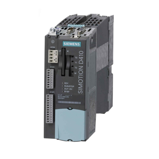
Description 2.3 SIMOTION D410 DP display SIMOTION D410 DP display View The following figure shows SIMOTION D410 DP with the interfaces and front elements. Figure 2-2 Location of interfaces and front elements in SIMOTION D410 DP Note The label underneath the mode selector lists the switch settings for the operating states of the SIMOTION D410. - Page 27 Description 2.3 SIMOTION D410 DP display Interfaces The SIMOTION D410 DP interfaces are described in the following tables. Table 2-5 SIMOTION D410 interfaces Interface Description Digital inputs/outputs 12-pin Mini Combicon: X121 ● 4 digital inputs: for connecting switches or proximity sensors ●...
- Page 28 Description 2.3 SIMOTION D410 DP display The type plate below is located on the front of the SIMOTION D410 DP. Figure 2-4 SIMOTION D410 DP nameplate (example) Note The contents of the individual nameplate fields on the current module may differ from those described in this Manual (e.g., updated product status, space for approvals and...
-
Page 29: Simotion D410 Pn Display
Description 2.4 SIMOTION D410 PN display SIMOTION D410 PN display View The following figure shows SIMOTION D410 PN with the interfaces and front elements. Figure 2-5 Location of interfaces and front elements in SIMOTION D410 PN SIMOTION D410 Manual, 04/2014... - Page 30 Description 2.4 SIMOTION D410 PN display Interfaces The SIMOTION D410 PN interfaces are described in the following tables. Table 2-6 SIMOTION D410 interfaces Interface Description Digital inputs/outputs 12-pin Mini Combicon: X121 ● 4 digital inputs: for connecting switches and proximity sensors ●...
-
Page 31: The Compactflash Card
Manual (e.g., updated product status, space for approvals and identifications, etc.). The CompactFlash card CF card CF cards with different storage capactities are available for SIMOTION D410. At the time of writing, these were: ● 1-GB CF, order number 6AU1400-2PA0*-0AA0 ● 512-MB CF, order number 6AU1400-2NA00-0AA0... - Page 32 Z option. Available Z options / licenses for SIMOTION D CF cards The following Z options are available for SIMOTION D410: TControl temperature control: ● Txx - TControl license and number (e.g. T03 = 3 TControl licenses) SIMOTION IT: ●...
-
Page 33: Licensing
Licensing SIMOTION D410 licensing SIMOTION D410 is a modular drive system for single-axis applications. D410 contains the motion control technology functions for precisely one real axis (speed control, positioning, synchronous operation, cam). This means that these technology functions do not require an additional license. -
Page 35: Operation (Hardware)
Operation (hardware) Overview of operator controls and indicators The following figure shows the operator controls and indicators arrangement on the SIMOTION D410. Figure 3-1 Operator controls and indicators SIMOTION D410 Manual, 04/2014... -
Page 36: Operator Controls
Service and operating mode switches DIP switches The SIMOTION D410 features operating mode and service selector switches at the bottom of its front side (see Overview of operator controls and indicators (Page 35)). These function using a DIP switch (DIP = Dual In Line Package), where: ●... - Page 37 In the "RUN" setting (S1, S2, and S3 = ON; S4 to S7 = OFF), you can even control the SIMOTION D410 operating mode using the SIMOTION SCOUT engineering system. This means that it is not necessary to adjust the DIP switch in order to change the operating mode.
-
Page 38: Simotion Compactflash Card
(see "Overview of operator controls and indicators"). Characteristics of the CF card The CF card is mandatory for operation of SIMOTION D410. The CF card must be ordered as a separate component; it is not included in the SIMOTION D410 scope of delivery. -
Page 39: Error And Status Indicators
System data, connection values, dimensions and weight (Page 87) Error and status indicators Arrangement of LED displays The LED displays are located under the CF card plug-in slot on the SIMOTION D410 (see the section titled Overview of operator controls and indicators (Page 35)). Further information SIMOTION D410 Commissioning Manual. -
Page 41: Interfaces
Interfaces Overview of interfaces This chapter describes the SIMOTION D410 interfaces. Available interfaces Table 4-1 Overview of available SIMOTION D410 interfaces Interface Designation Connector type Digital inputs X121 Mini Combicon, 12-pin Digital inputs/outputs X121 Mini Combicon, 12-pin DRIVE-CLiQ interface X100... -
Page 42: Digital Inputs/Outputs
1 signal: 15...30 V ● Input delay, typ. (hardware, for DI 8): – 0 → 1 signal: 50 μs – 1 → 0 signal: 100 μs ● Input delay, typ. (hardware, for DI 9 - 11) SIMOTION D410 Manual, 04/2014... - Page 43 Note If digital outputs are used, an external 24 V supply is required across terminal X124. If the 24 V supply is briefly interrupted, the digital outputs are deactivated for this time. SIMOTION D410 Manual, 04/2014...
- Page 44 Interfaces 4.2 Digital inputs/outputs Connection and circuit diagram The following figure shows the wiring and block diagrams of the digital inputs/outputs using the example of a SIMOTION D410 DP. SIMOTION D410 Manual, 04/2014...
- Page 45 Interfaces 4.2 Digital inputs/outputs Figure 4-1 Connection example SIMOTION D410 Manual, 04/2014...
-
Page 46: Drive-Cliq Interface
Switches or proximity encoders (2- or 3-wire encoders) can be connected. Bidirectional digital inputs/outputs 4 digital inputs/outputs (DI/DO) are available on the SIMOTION D410. The following application options are available when configuring the DI/DO as digital inputs: ● The DI/DO9, 10 and 11 can be used as "fast inputs" for measuring inputs or for external zero marks. - Page 47 Signal type: I = Input; O = Output; VO = Voltage Output Connectable devices The following table contains the components that can communicate with SIMOTION D410 via the DRIVE-CLiQ interface. Note the max. number of nodes that can be connected to the DRIVE-...
- Page 48 The following figures show 2 example topologies of components that can be connected to the DRIVE-CLiQ. Figure 4-2 Example topology: 3 Terminal Modules, 1 encoder via motor with a DRIVE-CLiQ interface, 1 encoder via SMx SIMOTION D410 Manual, 04/2014...
-
Page 49: Profibus Dp Interface (Simotion D410 Dp Only)
● PROFIBUS DP interface (SIMOTION D410 DP only) SIMOTION D410 DP provides one interface to connect to PROFIBUS DP. The interface can be run asynchronously or isochronously. A baud rate of up to 12 Mbit/s can be set for the PROFIBUS DP interface. - Page 50 SIMOTION D410 includes master and I-slave functionality. Note If a SIMOTION D410 DP is operated as a passive PROFIBUS I-slave, the display, measuring functions, and controller optimization engineering functions will be very slow. If possible, use the "active I-slave" setting for local commissioning (which does mean that an equidistance is no longer possible) and for complete commissioning, switch to "passive I-slave".
-
Page 51: Profinet Interface (Simotion D410 Pn Only)
PROFINET is an open component-based industrial communication system using Ethernet for distributed automation systems. SIMOTION D410 PN includes a PROFINET interface with 2 ports (X200 and X201). The PROFINET interface supports operation of a SIMOTION D410 PN as an IO controller and/ or as an I device. SIMOTION D410... -
Page 52: Encoder Interface (Htl/Ttl/Ssi)
● Other SINAMICS drive units (e.g., CU310 PN or CU320 with CBE20) See also Connecting the PROFINET interface (D410 PN only) (Page 82) Encoder interface (HTL/TTL/SSI) The HTL/TTL/SSI encoder interface is used to connect external encoders. SIMOTION D410 Manual, 04/2014... - Page 53 Make sure that you can operate the connected encoder on a 24 V power supply (e.g. HTL encoder). This setting can be set in the expert list of the drive in parameter p0400 and in the following parameters. SIMOTION D410 Manual, 04/2014...
- Page 54 For Pin 6 / Pin 9: At an encoder supply of 5 V, the voltage drops on the encoder supply cables are recorded and compensated by means of the sense cables. For this purpose, the encoder supply is adjusted to the SIMOTION D410.
-
Page 55: Ep Terminals/Temperature Sensor Connection
X121 (X121.1 to X121.4). Using the temperature sensor connection, you can connect the temperature sensing via KTY (special temperature sensor) or PTC (positive temperature coefficient). The temperature sensing provides thermal motor protection by detecting critical motor conditions. SIMOTION D410 Manual, 04/2014... - Page 56 For more information on "thermal motor protection", see the Manual. Note For SIMOTION D410, the following safety functions are available with version V4.1 SP2 and higher: ● Safety Integrated Basic Functions via the EP terminals ● Safety Integrated Extended Functions with TM54F ●...
-
Page 57: Power Supply
. Power supply SIMOTION D410 can be supplied with power by connecting a PM340 power module. In the following situations, a 24 V DC load power supply must also be connected via X124: ● For supplying the digital outputs (X121) ●... - Page 58 Interfaces 4.8 Power supply ● For commissioning/diagnostics with deactivated Power Module supply voltage ● If the SIMOTION D410 is snapped on to a mounting plate and not on to a PM340 Power Module Note A control DC power supply is required to operate a motor with an integrated holding brake.
-
Page 59: Measuring Sockets
The T0 - T2 measuring sockets are used to output analog signals Any interconnectable signal can be output to any measuring socket on the control unit. Note The measuring sockets are suited for multiple-spring wire connectors with a diameter of 2 mm. SIMOTION D410 Manual, 04/2014... -
Page 60: Power Module Interface
4.10 Power Module Interface SIMOTION D410 can be connected to a SINAMICS S120 PM340 blocksize power module via the power module interface. Note SIMOTION D410 can only be connected to a SINAMICS S120 PM340 blocksize power module via the power module interface. -
Page 61: Assembling
● Operation away from the Power Module: SIMOTION D410 is mounted on a mounting plate. Open device SIMOTION D410 is an open device! This means, you can only install the modules in housings, cabinets or electrical equipment rooms. These may only be accessible via key or tool. -
Page 62: Simotion D410 Mounted On The Power Module
AC/AC are connected to SIMOTION D410 via the DRIVE-CLiQ interface of the Power Module. Requirement As soon as the PM340 Power Module is properly installed, you can mount the SIMOTION D410 on the Power Module. Note Take note of the associated user documentation when commissioning the Power Module! - Page 63 Assembling 5.2 SIMOTION D410 mounted on the power module Mounting on the Power Module Snapping the SIMOTION D410 onto the PM340 PM340 Power Module with SIMOTION D410 Power Module SIMOTION D410 Manual, 04/2014...
-
Page 64: Mounting Simotion D410 On The Mounting Plate
Assembling 5.3 Mounting SIMOTION D410 on the mounting plate Disassembling SIMOTION D410 To remove SIMOTION D410 from the Power Module, the blue release, as shown in the figure, must be pressed down and SIMOTION D410 tilted forward. Figure 5-1 Removing the SIMOTION D410 from the PM340 Power Module... - Page 65 Assembling 5.3 Mounting SIMOTION D410 on the mounting plate Requirements You must order the mounting plate for SIMOTION D410 separately. See Chapter "Spare Parts and Accessories" for the order number. Mounting on mounting plate 1. The mounting plate is attached to the control cabinet.
-
Page 66: Mounting Simotion D410 In The Power Module Chassis
Assembling 5.4 Mounting SIMOTION D410 in the Power Module Chassis Mounting SIMOTION D410 in the Power Module Chassis Figure 5-3 Mounting the CU310, for example, in the Power Module Chassis, FX frame size The DRIVE-CLiQ cable and the cable for the 24 V supply must be correctly routed so that the front flap can close. -
Page 67: Connecting
For further information on EMC, we recommend the configuration manual Guidelines / Basic System Requirementsn , order number 6FC5297-0AD30-0AP3. Standards and regulations You must comply with the applicable VDE guidelines when wiring the SIMOTION D410, in particular VDE 0100 and VDE 0113 for disconnecting devices, short-circuit and overload protection. - Page 68 Connecting 6.2 General rules for operating the SIMOTION D410 System startup after certain events The following table identifies considerations required for startup of a system following certain events. Table 6-1 System startup When ... then ... Startup after voltage drop or power loss no dangerous states must result.
-
Page 69: Safety Information For Wiring
Safety information for wiring Requirement You have mounted the Control Unit in the control cabinet. The SIMOTION D410 control unit has a protective conductor connection (M4 screw, Torx T20). This connection is also for the connection of an equipotential bonding conductor. Note Requirements for functional safety for machines and systems;... - Page 70 (e.g. control cabinet door via hinges Example: Booksize axis grouping comprising Control Unit (CU), Line Module (LM), and Motor Modules (MM) as well as drive in blocksize format comprising a Power Module (PM) with snapped on Control Unit (CU) SIMOTION D410 Manual, 04/2014...
- Page 71 A mounting plate serves simultaneously as an equipotential bonding surface. This means that no additional equipotential bonding is required within the drive line-up. If a common bright ⑨ mounting plate is not available, then equally good equipotential bonding must be SIMOTION D410 Manual, 04/2014...
- Page 72 If, for example, data cables (PROFIBUS, PROFINET, Ethernet or DRIVE‑CLiQ) are routed through several control cabinets, equipotential bonding must be established with an equipotential bonding conductor. Install the equipotential bonding conductor together with the data cable. The following minimum cross-sections are required according to IEC 60364-5-54: SIMOTION D410 Manual, 04/2014...
- Page 73 Further information on the protective connection and equipotential bonding can be found in the following references: ● SINAMICS drive system: See the SINAMICS manuals ● PROFIBUS and PROFINET: See the following Internet address (http://www.profibus.com) (at Downloads) SIMOTION D410 Manual, 04/2014...
-
Page 74: Overview Of Simotion D410 Connections
WARNING Danger to life from electric shock due to insufficient grounding Ensure the connection to the protective ground is low resistance. Provide a flexible cable to the protective conductor if SIMOTION D410 is mounted on a movable frame. SIMOTION D410... -
Page 75: Connecting The Power Supply
Wire-end sleeves are required if you wire several cables per connection. 1. Strip the cable ends. 2. Put on the wire-end sleeve if applicable. 3. Plug the cable end (with wire-end sleeve) into the screw-type terminal connection. SIMOTION D410 Manual, 04/2014... -
Page 76: Connecting Drive-Cliq Components
● Ring wiring is not permitted. ● Components must not be double-wired. Connecting DRIVE-CLiQ components Connect the SIMOTION D410 X100 socket to the corresponding sockets on the drive components using the DRIVE-CLiQ signal cable (motor with DRIVE-CLiQ interface, TM and SMx modules). -
Page 77: Connecting Digital I/Os
This provides you with the option to expand the subnet if needed, e.g., with a PG or SIMATIC HMI device. Use RS 485 repeaters for the connection between segments and to extend the cable. SIMOTION D410 Manual, 04/2014... -
Page 78: Profibus Cables And Connectors
The bus connector is used to connect the PROFIBUS cable to the PROFIBUS DP interface (X21), thus establishing a connection to additional nodes. You will find an overview of the bus connectors available for order in the chapter titled "Spare parts and accessories". SIMOTION D410 Manual, 04/2014... -
Page 79: Profibus Cable Lengths
(dA = external cable diameter): Table 6-9 Boundary conditions for routing of PROFIBUS cables Features Boundary conditions Bending radius for a single bend 80 mm (10 x dA) Bending radius for multiple bends 160 mm (20 x dA) SIMOTION D410 Manual, 04/2014... -
Page 80: Connecting Profibus Dp (Interface X21)
3. If the bus connector is located at the start or end of a segment, you must connect the terminating resistor (switch setting "ON"). Figure 6-4 Terminating resistor switched on and off Note Make sure that the nodes at which the terminating resistor is located are always supplied with voltage during startup and operation. SIMOTION D410 Manual, 04/2014... -
Page 81: Connection Rules In The Profibus Subnet
This means that when a bus segment contains an RS 485 repeater, the bus segment can contain no more than 31 additional nodes. However, the number of RS 485 repeaters does not affect the maximum number of nodes on the bus. SIMOTION D410 Manual, 04/2014... -
Page 82: Connecting The Profinet Interface (D410 Pn Only)
PROFIBUS DP connector at the first and last node and switching off the other terminating resistors. Networking example The following figure shows an example configuration of a subnet with SIMOTION D410 DP. Figure 6-5 Networking example 6.10... -
Page 83: Connecting An External Encoder
You will find an overview of the RJ45 plug connector available for order in the chapter entitled "Spare parts and accessories". Additional references Detailed information SIMOTION D410 Commissioning ● For information on assigning the IP address, refer to the Manual. SIMOTION Communication System Manual. - Page 84 Make sure that you can operate the connected encoder on a 24 V power supply (e.g. HTL encoder). This setting can be set in the expert list of the drive in parameter p0400 and in the following parameters. SIMOTION D410 Manual, 04/2014...
-
Page 85: Technical Data
Technical data SIMOTION D410 dimensional diagram Figure 7-1 SIMOTION D410 dimensional diagram SIMOTION D410 Manual, 04/2014... -
Page 86: Simotion D410 Mounting Plate Dimensional Diagram
Technical data 7.3 CAD data, dimension drawings, and circuit-diagram macros SIMOTION D410 mounting plate dimensional diagram Dimensions of the SIMOTION D410 mounting plate Figure 7-2 D410 mounting plate CAD data, dimension drawings, and circuit-diagram macros Dimension drawings and CAD data Dimension drawings, as well as 2D and 3D CAD data, can be generated in commonly used formats using CAD CREATOR. -
Page 87: System Data, Connection Values, Dimensions And Weight
Technical data 7.4 System data, connection values, dimensions and weight Circuit-diagram macros EPLAN circuit-diagram macros are available for SIMOTION D410. The macros are supported when you create circuit diagrams. For information on how to do this, refer to: Internet address (http:// support.automation.siemens.com/WW/view/en/31622426). - Page 88 512 Byte (PROFIBUS Integrated) Address space for each PROFINET device 1400 Byte General technical data The SIMOTION D410 has an integrated fan. Table 7-7 SIMOTION D410 electrical connection values Power supply 24 V DC (permissible range: 20,4 ... 28.8 V)
- Page 89 Technical data 7.4 System data, connection values, dimensions and weight Table 7-8 SIMOTION D410 dimensions and weight Dimensions W x H x D 73 x 183,2 x 89,6 mm SIMOTION D410 weight - Without packaging 990 g - With packaging...
-
Page 90: Digital Inputs/Outputs
● 24 V DC ● For signal "1" ● 15 … 30 V ● For signal "0" ● -3 … +5 V Electrical isolation Current consumption typical at 1 signal level 10 mA at 24 V SIMOTION D410 Manual, 04/2014... -
Page 91: Clock
Reproducibility is cycle dependent. Short cycle times must be used for good reproducibility Clock Features of real-time clock The table below contains the features and functions of the Control Unit clock. Table 7-15 Clock features Features Description Type Hardware clock (integrated "real-time clock") Default setting when delivered DT#1992-01-01-00:00:00 SIMOTION D410 Manual, 04/2014... -
Page 92: Shipping And Storage Conditions
(excluding software clock). The buffer is recharged in the POWER ON state. If the real-time clock backup time is exceeded, the time is reset. If the SIMOTION D410 is reset to its factory settings, the clock is also reset to the "default setting when delivered". - Page 93 ● Shock load: DIN EN 60721-3-3, Class 3M4 ● Free fall: DIN EN 60721-3-2, Class 2M1 and 2M2 ● Toppling: DIN EN 60721-3-2, Class 2M1 The mechanical ambient conditions for SIMOTION D410 are listed in the following table in the form of sinusoidal vibrations. Table 7-17...
- Page 94 Technical data 7.8 Mechanical and climatic ambient conditions Climatic ambient conditions SIMOTION D410 may not be used under the following climatic ambient conditions: Note Observe the application ranges of the PM340 power modules along with their derating. For further information, see SINAMICS documentation.
-
Page 95: Spare Parts/Accessories
Insufficient ventilation clearances result in overheating and therefore in more failures and a shortened life of the component. Maintain 50 mm ventilation clearances above and below the component. Additional references SIMOTION D410 Commissioning Manual. For further information on TM31, see the Terminal module TM41 Characteristics of the TM41 With the TM41 Terminal Module, the number of available digital inputs/digital outputs and the number of analog inputs within a drive system can be expanded. -
Page 96: Tm54F Terminal Module
Spare parts/Accessories 8.3 TM54F terminal module use of the TM41 on the SIMOTION D410 is limited, as precisely one real axis can be configured SIMOTION D410 on the SIMOTION D410. You can find more information in the Commissioning Manual. The TM41 contains the following terminals:... -
Page 97: Terminal Modules Tm15 And Tm17 High Feature
(DI), digital output (DO), a measuring input input, or an output cam output. TM15 DI/DO Each of the 24 isolated digital I/Os can be configured on a channel-specific basis as a digital input (DI) or digital output (DO). The digital I/Os can be interconnected using BICO technology SIMOTION D410 Manual, 04/2014... - Page 98 Maintain 50 mm ventilation clearances above and below the component. Additional references SIMOTION Detailed information about the TM15 and TM17 High Feature can be found in the Terminal Modules TM15 / TM17 High Feature Commissioning Manual. SIMOTION D410 Manual, 04/2014...
-
Page 99: Cua31/Cua32 Control Unit Adapter
The 50 mm clearances above and below the components must be observed. The ventilation openings may not be covered by connecting cables. Additional references You will find more information on the CUA31/CUA32 control unit adapter in the SINAMICS S120 AC Drive Manual. SIMOTION D410 Manual, 04/2014... -
Page 100: Dmc20/Dme20 Drive-Cliq Hub
Weidmüller GmbH & Co. KG, see: Internet address (http://www.weidmueller.com) Protective conductor connection M4/1.8 Nm e.g. from Weidmüller GmbH & Co. KG, see: Internet address (http://www.weidmueller.com) Mounting plate for operation away from the Power Module 6AU1400-7AA05-0AA0 Spare fan for SIMOTION D410 6SL3064-0AC00-0AA0 SIMOTION D410 Manual, 04/2014... - Page 101 PM 21 Catalog. Motor Modules, DRIVE-CLiQ cables, etc., see the Note If the fan for the SIMOTION D410 is defective, it can be replaced. The procedure for replacing SIMOTION D410 Commissioning Manual. the SIMOTION D410 fan is described in the...
- Page 102 In order to view the spare parts, you require the order number and the serial number of the module. Both numbers can be found on the type plate on the module or the packaging label. SIMOTION D410 Manual, 04/2014...
-
Page 103: Standards And Approvals
EMC-compliant configuration of the plant are described in this Manual and/or the Configuration Manual "EMC Installation Guideline". Please note that ultimately it is always the label on the device that provides the decisive information on the compliance with standards. SIMOTION D410 Manual, 04/2014... -
Page 104: Device-Specific Information
It is essential to follow the installation instructions in the SINAMICS S120 Manuals in order to ensure compliance with emitted interference and immunity values. The same installation instructions apply for the SIMOTION D410 control unit as for the SINAMICS S120 CU310 control unit with regard to EMC. -
Page 105: Esd Directives
This figure indicates the maximum electrostatic charges that can accumulate on an operator when he comes into contact with the indicated materials. These values comply with the specifications in IEC 801-2. SIMOTION D410 Manual, 04/2014... -
Page 106: Basic Measures For Protection Against Discharge Of Static Electricity
If you have to take measurements on a module, make sure that you first discharge any static that may have accumulated in your body. To do this, touch a grounded metal object. Only use grounded measuring instruments. SIMOTION D410 Manual, 04/2014... -
Page 107: Index
Wiring, 76 CompactFlash card, 32, 89 Licenses, 32 Representation, 32 Slot, 38 Electrical connection values, 88 Type plate, 32 Electromagnetic compatibility, 103 Component EMC directives, 103 on DRIVE-CLiQ, 25 Encoder interface, 52 on PROFIBUS DP, 22 SIMOTION D410 Manual, 04/2014... - Page 108 Features, 78 Power Module Interface, 60 Rules for cabling, 79 PROFIBUS DP, 50 PROFIBUS DP PROFINET, 51 Connectable devices, 51 SIMOTION D410, 41 Connectors, 51 Temperature sensor connection, 55 Interface, 50 IRT, 82 Interface assignment, 50 Interface characteristics, 50 PROFIBUS subnet...
- Page 109 Temperature sensor connection, 55 Terminal Module TM15, 97 TM15 DI/DO, 97 TM17 High Feature, 97 TM31, 95 TM41, 96 TM54F, 96 Terminating resistor, 78 Type plate CF card, 32 SIMOTION D410 DP, 27 SIMOTION D410 PN, 30 SIMOTION D410 Manual, 04/2014...
Need help?
Do you have a question about the SIMOTION D410 and is the answer not in the manual?
Questions and answers