Table of Contents
Advertisement
Advertisement
Table of Contents

Related Manuals for Siemens SIPART DR21


Summary of Contents for Siemens SIPART DR21
- Page 1 SIPART DR21 6DR 210*--* Edition 08/2010 Manual SIPART DR21 C73000-B7476-C143-08...
- Page 2 SIPART DR21 C73000-B7476-C143-08...
- Page 3 Copyright e Siemens AG 1999 All rights reserved Disclaimer of Liability The reproduction, transmission or use of this docu-...
- Page 4 Trademarks SIMATICR, SIPARTR, SIRECR, SITRANSR registered trademarks of Siemens AG. Third parties using for their own purposes any other names in this document which refer to trade- marks might infringe upon the rights of the trademark owners. SIPART DR21 C73000-B7476-C143-08...
- Page 5 Signalling lamp for computer switched off (with w Further messages Signalling lamp for adaptation procedure running Signalling lamp for “Limit triggered” Note Operation can be blocked using the digital signal bLb; exception: switching over o w/x digital display. SIPART DR21 C73000-B7476-C143-08...
- Page 6 Digital outputs S58 to S75 2DO Rel Limit monitors S76 to S80 x/w indicator Slot 3 Options Restart S84 to S91 conditions S82 to S83 Serial interface S84 to S91 ∽ +24 V +5 V Slot 4 SIPART DR21 C73000-B7476-C143-08...
-
Page 7: Table Of Contents
............SIPART DR21... -
Page 8: Table Of Contents
............... . SIPART DR21... -
Page 9: General Part -- Fundamental Control Technology Terms
Electric actuators, consisting of an electric motor and gear unit. These have an integral action and are driven by three-position step controllers. Electric actuators are also poss- ible with an integrated (series-connected) positioner and then have a proportional action and can be driven by continuous controllers. SIPART DR21 C73000-B7476-C143-08... - Page 10 If disturbance variables are present, a steady-state deviation may result depending on Kp · xd Figure 1-3 Step-forced response of P controller SIPART DR21 C73000-B7476-C143-08...
- Page 11 The PID controller results in improvement of the dynamic control quality as a result of the additional application of a D component. Refer to the PD and PI controllers. Kp · xd Figure 1-6 Step-forced response of PID controller SIPART DR21 C73000-B7476-C143-08...
- Page 12 Feedback with time response Control amplifier Actuator Figure 1-7 Function diagram of three-position step controller The output response to the three-position amplifier in conjunction with the integral-action actuator permits a “continuous” manipulated variable taking into account the response threshold. SIPART DR21 C73000-B7476-C143-08...
- Page 13 Controlled variable System deviation Manipulated variable Transmitter Stepoint adjuster Control amplifier Electropneumatic signal 0.2 to 1 bar converter Pneumatic actuator Figure 1-9 Function diagram of continuous controller This type of controller is preferentially used in the chemical industry. SIPART DR21 C73000-B7476-C143-08...
- Page 14 Command variable Controller Controlled variable Controlled system Manipulated variable ON/OFF Setpoint adjuster Disturbance variable Figure 1-10 a) Function diagram b) Switching ouptupt and response of controlled variable SIPART DR21 C73000-B7476-C143-08...
- Page 15 1 General Part -- Fundamental control technology terms Two-position controller with feedback In modern two-position controllers with feedack -- such as the SIPART DR21 -- the switching response is determined by the period, the system deviation and the para- meters. The period T is set as a fixed value in the controller. The system deviation xd in conjunctionw ith the parameters Kp/Tn/Tv determines the duty factor (ON/OFF ratio) within the period.
- Page 16 1 General Part -- Fundamental control technology terms Manual SIPART DR21 C73000-B7476-C143-08...
-
Page 17: Technical Description
1 three-pin plug at 115/230 V AC or special plug at 24 V UC 2 Clamps, pluggable 2 Adhesive labels ”Power supply 115 V” (for 115/230 V-version). 1 CD ROM with documentation D Standard controllers The following variants of the SIPART DR21 are available: Order number: Output stage Power Supply 6DR2100-4... -
Page 18: Range Of Application
The controller’s great flexibility makes it suitable for use in simple or intermeshed control cir- cuits. The wide setting range of the control parameters allow the SIPART DR21 to be used in process engineering both for fast (e.g. flow) and slow controlled systems (e.g. tempera- ture). -
Page 19: Features
SIPART DR21 offers the following features: D Analog inputs Two analog inputs for current 0/4 to 20 mA, without potential isolation The SIPART DR21 controller can be expanded to a total of 4 analog inputs with signal converters. The following signal converters are available:... - Page 20 Slot assignment, see figure 2-2 Rear view, page 25. D Power supply unit The power supply unit is designed for the following voltages depending on the standard con- troller: 230 V/115 V AC, switchable by plug-in jumpers in the instrument. 24 V UC SIPART DR21 C73000-B7476-C143-08...
- Page 21 Hold on setpoint change (setpoint ramp) +yBL / --yBL Direction-dependent blocking of the manipulated variable Direction-dependent limiting of the manipulated variable by external signals, e.g. from the limit switches of the actuating drives. This limiting is effective in every operating mode. SIPART DR21 C73000-B7476-C143-08...
- Page 22 5 x DI Slot 3 5 binary inputs 24 V 2 x relays Slot 3 2 relay outputs 35 V D Serial interface An interface can be retrofitted with signal converters for RS 232/RS 485 or PROFIBUS DP. SIPART DR21 C73000-B7476-C143-08...
- Page 23 A system fault can be output via the digital out- (pg. 165) put MUF. Adaptation of the SIPART DR21 operates with normal direction in the factory Structure switch direction of action setting. The direction of the controller can be changed for S46;...
-
Page 24: Design
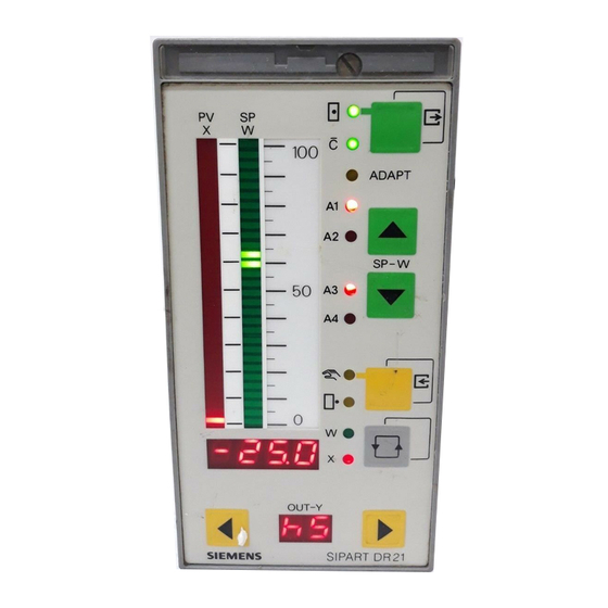
SIPART DR 20/22/24-controller-family with color coded assignment of the display- and control elements. For better monitoring of the process, SIPART DR21 has user-friendly analog displays for the setpoint- and actual value display, a four-digit digital display which can be set for setpoint,... - Page 25 (scope of delivery of the relay module) Terminal block 1 AI1 to AI2 (I) Terminal block 2 DI1 to DI2 DO1 to DO2 24 V L+; M Terminal block 3 Digital outputs ± Δ Figure 2-2 Rear view SIPART DR21 C73000-B7476-C143-08...
-
Page 26: Function Principle
D Analog inputs AI1 and AI2. The analog inputs of the SIPART DR21 are designed for 0/4 to 20 mA input signals. The in- puts have an input load resistance of 248 Ω and are potential-bound. The start value 0 mA or 4 mA is determined by the structure switches S4 and S5. - Page 27 No programming knowledge is necessary (see Operation, chapter 5, page 149). All settings are made without exception on the front operating panel of the SIPART DR21 or the serial interface. The job-specific program written in this way is saved in the non-volatile user program mem- ory.
-
Page 28: Option Module
Resistors are switched parallel to the potentiometer by settings on the module and a rough range selection made. Start of scale and -- full scale are set with the two adjusting pots on the back of the module. SIPART DR21 C73000-B7476-C143-08... - Page 29 This terminal is used in connection with the UNI-module for temperature measuring with thermocouples at an internal reference point. It consists of a temperature sensor which is pre-assembled on a terminal block and plated to avoid mechanical damage. SIPART DR21 C73000-B7476-C143-08...
- Page 30 The inputs are designed in 24-V-logic and are potential-bound. The functions are assigned to the inputs- and outputs by configuration of the controller. (Structure switches S23 to S33, S58 to S68). The digital outputs are short-circuit-proof and can drive commercially available relays or the interface relays 6DR2804-8A/8B directly. SIPART DR21 C73000-B7476-C143-08...
- Page 31 SIPART-controller. Internet address: www.fielddevices.com [Edition: 05.2000]) The SIPART S5 DP and SIPART S7 DP programs are offered for DP-masters SIMATIC S5 and SIPART DR21 C73000-B7476-C143-08...
- Page 32 Can be used in slot 4, the structure switches S84 to S91 must be set for the transmission procedure. For connecting the controller SIPART DR21 to a master system for control and monitoring. All process variables can be sent, the external setpoint, tracking variable, operating states, parameters and structurings sent and received via the interface.
- Page 33 These voltages are available at the open re- lay contact. Therefore such motors may only be controlled under observance of the technical data and the pertinent safety conditions via approved switching elements. SIPART DR21 C73000-B7476-C143-08...
-
Page 34: Technical Data
D Spurious emission, interference immunity according to EN 61 326, NAMUR NE21 8/98 Weight, standard controller approx. 1.2 kg Color Front module frame RAL 7037 Front surface RAL 7035 Material Housing, front frame Polycarbonate, glass-fiber reinforced Front foil Polyester Backplanes, modules Polybutylenterephthalate SIPART DR21 C73000-B7476-C143-08... - Page 35 Installation depth necessary for changing the main board and modules relay module 6DR2804-8A/B Figure 2-5 Dimensions SIPART DR21, dimensions in mm Number of Cut-out controllers width b Under consideration of the permissible ambient tempera- ture, tight installation one above the other is allowed...
-
Page 36: Standard Controller
Static destruction limit ±40 mA Parameterizable transmitter fault message AI1/2 0 mA to 20 mA ≤-0.5 %; ≥106.25 % 4 mA to 20 mA ≤-2.5 %; ≥106.25 % AI3/4 0/4 mA to 20 mA ≤-2.5 %; ≥106.25 % SIPART DR21 C73000-B7476-C143-08... - Page 37 ≤ 2.5 A Rating ≤ 1250 VA ≤30 W at 250 V ≤100 W at 24 V Applies for interference acc. to IEC 801-3 to 3 V/m, with 10 V/m at 290 to 310 MHz ≤4.3 % SIPART DR21 C73000-B7476-C143-08...
- Page 38 Full scale ≤ 0.1 %/10 K of the modulation range Setpoint- and manipulated variable adjustment Setting With 2 keys (more - - less) Speed progressive Resolution 1 digit 0.1 % of rated range 0 to 20 mA SIPART DR21 C73000-B7476-C143-08...
- Page 39 -- y-display (digital) 2digit 7-segment-LED Color Digit height 7 mm Display range 0 to 100 % -9 % to 109 %, display >99 % h0 to h9 Overrun Adjustable 0.1 s to 9.9 s Refresh rate Resolution SIPART DR21 C73000-B7476-C143-08...
- Page 40 Start of measuring by structuring Without errors of A/D-converter with R = RA +ΔR + RE adjustable in three ranges: R = 200 Ω, R = 500 Ω, R = 1000 Ω Table 2-2 Technical data for module 6DR2800-8J/R SIPART DR21 C73000-B7476-C143-08...
- Page 41 Types, see structure switches, internal reference point (plug-in terminal block) 6DR2805-8A Reference to parameterizable span = ME -- MA Δ In series with adaptive filter changeable by time constant t3 (onPA) Table 2-3 Technical data for UNI-module 6DR2800-8V SIPART DR21 C73000-B7476-C143-08...
- Page 42 -- Service life mechanical 2x10 switching cycles electrical 24 V/4 A ohmic 2x10 switching cycles 24 V/1 A inductive 2x10 switching cycles -- Spark quenching element Series circuit 1 μF/22 Ω parallel to it varistor 75 Vrms SIPART DR21 C73000-B7476-C143-08...
- Page 43 Time monitoring of the data communication structurable on the controller in connection with DP-watchdog Electrical isolation between Rxd/Txd-P/-N and the controller 50 V UC common mode voltage Test voltage 500 V AC Repeater-control signal CNTR-P TTL-level with 1 TTL-load SIPART DR21 C73000-B7476-C143-08...
- Page 44 Round cable with shield RS 232 point- ≤2.5 nF 50 m 10 m to-point RS 485 bus ≤250 nF 1,000 m 1,000 m SIPART bus operation is no longer possible! The bus driver is no longer available! SIPART DR21 C73000-B7476-C143-08...
- Page 45 II and degree of contamination 2 according to DIN EN 61010 Part 1 Type of protection Housing IP50 according to DIN 40050 Connections (in plugged state) IP20 according to DIN 40050 SIPART DR21 C73000-B7476-C143-08...
- Page 46 DIN EN 50022 NS 35/15 DIN EN 50035 NS 32 DIN EN 50035 see fig. 2-7 Dimensioned drawing NS 35/15 NS 32 NS 35/7.5 131.5 Center of the mounting rail Figure 2-7 Dimensioned drawing coupling relay, dimensions in mm SIPART DR21 C73000-B7476-C143-08...
-
Page 47: Functional Description Of The Structure Switches
OR link. The error message is acknowledged with the Shift key (12). The fault message signal via the OR link is available until the selected analog inputs are back in the working range. SIPART DR21 C73000-B7476-C143-08... - Page 48 The controllers- or process variables are available for assignment to the analog output (S6) and the limit value signal (S76 to S80) and can be read in via the SES. With this input structure most control tasks can be solved in connection with the different controller types and controller output structures. SIPART DR21 C73000-B7476-C143-08...
- Page 49 Manual Functional description of the structure switches Analog input signal processing (S3 to S21) Figure 3-1 Analog input signal processing SIPART DR21 C73000-B7476-C143-08...
-
Page 50: Digital Input Signal Processing (S23 To S41)
The CB-signal is formed at S85 = 2, (4) as an OR-function of CB via the serial interface and CB via a digital input so that operation can take place optionally with one signal. as of software version --A5 SIPART DR21 C73000-B7476-C143-08... - Page 51 3/4 the connection is made dynamically, i.e. every positive edge causes manual-automa- tic-manual operation switching. In addition, with structure switch S51 = 4 the locking of He with RC = Int CB is released. ∨ as of software version --A5 SIPART DR21 C73000-B7476-C143-08...
- Page 52 24 V +yBL 5DI S22=2 Slot 3 -yBL 24 V 4DO+2DI S22=1 bLPS only for CB (S23) and P (S27) as of software --B5 Figure 3-2 Assignment and direction of action of the digital inputs S23 to S40 SIPART DR21 C73000-B7476-C143-08...
- Page 53 --A5 as of software version --B3 as of software version --B5 as of software version --C1 Figure 3-3 Linking the digital inputs DI1 to DI7 with the control signals via the SES (S41, S42, S51, S85) SIPART DR21 C73000-B7476-C143-08...
- Page 54 Direction-dependent blocking of the manipulated variable yBL Direction-dependent limiting of the manipulated variable by external signals, e.g. from the limit switches of the actuating drives. This limiting is effective in every operating mode. SIPART DR21 C73000-B7476-C143-08...
-
Page 55: Controller Types (S1, S42 To S45)
1. With the control signal tS = 1 the set setpoint ramp is switched off (the setpoint then changes suddenly). With the setpoint ramp, sudden setpoint switchings to the untracked variables SH, wi, w S45 = 1 and w can be avoided. EA , as of software version –A5 SIPART DR21 C73000-B7476-C143-08... - Page 56 Since it can normally be assumed that, especially in manual operation and in DDC-operation, the actual value has been driven to the desired value dur- ing manual- or DDC-operation, the tracked setpoint then corresponds to the rated value. SIPART DR21 C73000-B7476-C143-08...
- Page 57 With S23, the CB-signal can be set to Low or High or assigned to a digital input, (see fig- ure 3-2, page 52). The factory setting is S23 = 8, CB = High. The setpoint switching can be varied freely with these structuring possibilities. SIPART DR21 C73000-B7476-C143-08...
- Page 58 The display range set with dP, dA and dE is transferred depending on the controller type (S1) to the parameters and setpoints which can be assigned to the displayed variable: With the appropriate assignment, this also applies for the limit value alarms A1 to A4, see chapter 3.10.3, page 117. SIPART DR21 C73000-B7476-C143-08...
-
Page 59: Fixed Setpoint Controller With 2 Independent Setpoints (S1 = 0)
Int and CB according to table 3-1, page 60. Signaling of the active setpoint takes place on the LEDs Internal and C. As soon as a LED lights, wi2 is active. SIPART DR21 C73000-B7476-C143-08... - Page 60 Identification of the displayed variables by the w- or x-signal lamp: 1 = steady light, 0.5 = flashing light, 0 = off Display order 0.5 (0 at S81=6) x-signal lamp w-signal lamp Table 3-2 Display levels (S81) SIPART DR21 C73000-B7476-C143-08...
- Page 61 · (x2 - c2 · x3+c3) page 49 Factory setting c1=c2=c3=0 0000 0000 Adaptation Note: S51=4 is recommended for this controller as of software version --A5 Figure 3-6 Block diagram S1 = 0, fixed setpoint controller with 2 independent setpoints SIPART DR21 C73000-B7476-C143-08...
-
Page 62: Slave Controller, Synchronized Controller, Spc-Controller
This controller type is used for cascade controls with 2 separate controllers (master- and slave controllers), for synchronized controls, fixed setpoint controls with external setpoint preset under console conditions with external setpoint generator and SPC-controls (setpoint control). SIPART DR21 C73000-B7476-C143-08... - Page 63 S23= 8) or only dependent on CB (S42=1, S23=1 to 7) as a slave controller with Internal/Exter- nal-switching. If the switching option is blocked in External position (S42=1, S23=8), the con- troller operates as a slave controller without Internal/External-switching. SIPART DR21 C73000-B7476-C143-08...
- Page 64 SH is achieved (see table 3-4, page 65) and table 3-5, page 66. D Controlled variable processing A 2-component control is implemented (disturbance variable connection). With factors c1 and c3 the main controlled variable x1 can connect the auxiliary controlled variable x2 with weighting. SIPART DR21 C73000-B7476-C143-08...
- Page 65 Factory setting (n) tracked to the value active before switching, therefore bumpless switching adjustable ↗ Factory setting Table 3-4 Slave-/synchronized-/SPC-controller with Internal-/External switching S1 = 1 with tracking of the inactive setpoint to the active S45 = 0 SIPART DR21 C73000-B7476-C143-08...
- Page 66 Factory setting adjustable ↗ Factory setting Table 3-5 Slave-/synchronized-/SPC controller with Internal-/External switching (SPC-controller), S1 = 1 without tracking of the active setpoint to the active setpoint S45 = 1, 2 or 3 setpoint oper- ation SIPART DR21 C73000-B7476-C143-08...
- Page 67 Manual Functional description of the structure switches Controller types (S1, S42 to S45) Figure 3-8 Block diagram S1 = 1 slave controller, synchronized controller, SPC-controller SIPART DR21 C73000-B7476-C143-08...
-
Page 68: Ddc-Fixed Setpoint Controller (S1 = 2)
CB and the Internal/External key: DDC-mode ≙ RC = Int∧CB = 1 0000 x - TRACKING +c6 · z P I D Int∧CB x=x1+c1 · (x2 - c2 · x3+c3) Figure 3-9 Control principle S1 = 2 SIPART DR21 C73000-B7476-C143-08... - Page 69 Internal key (16). The actual value can be indicated on the actual value display. SH as a flag pointer or wi can be indicated on the setpoint display. SIPART DR21 C73000-B7476-C143-08...
- Page 70 3 Functional description of the structure switches Manual 3.4 Controller types (S1, S42 to S45) Footnote explanation, see page 72 Table 3-6 DDC controller, S1 = 2, manual operation has priority over DDC operation S49 = 1 SIPART DR21 C73000-B7476-C143-08...
- Page 71 Manual Functional description of the structure switches Controller types (S1, S42 to S45) Footnote explanation, see page 72 Table 3-7 DDC controller, S1 = 2, manual operation has priority over DDC operation S49 = 1 SIPART DR21 C73000-B7476-C143-08...
- Page 72 (with tracking of the inactive setpoint to the active setpoint). At S45 = 1 (without tracking) and x-tracking, automatic operation starts with wi = x (xd = 0), the active setpoint runs to the old set value wi via the possibly set setpoint ramp tS. SIPART DR21 C73000-B7476-C143-08...
- Page 73 Identification of the displayed variables by the w- or x-signal lamp: 1 = steady light, 0.5 = flashing light, 0 = off Display order 0.5 (0 at S81=6) x-signal lamp w-signal lamp Table 3-9 Display levels (S81) SIPART DR21 C73000-B7476-C143-08...
- Page 74 3 Functional description of the structure switches Manual 3.4 Controller types (S1, S42 to S45) Figure 3-10 Block diagram S1 = 2, DDC fixed setpoint controller SIPART DR21 C73000-B7476-C143-08...
-
Page 75: Controlled Ratio Controller (S1 = 3)
I and II. A physical display is possible with dA, dE, dP. The controlled variable x1 and the evaluated commanding process variable w are displayed on the analog x - and w-displays respectively so that a direct control SIPART DR21 C73000-B7476-C143-08... - Page 76 Identification of the displayed variables by the w- or x-signal lamp: 1 = steady light, 0.5 = flashing light, 0 = off Display order 0.5 (0 at S81=6) x-signal lamp w-signal lamp Table 3-10 Display levels (S81) SIPART DR21 C73000-B7476-C143-08...
- Page 77 Manual Functional description of the structure switches Controller types (S1, S42 to S45) Figure 3-12 Block diagram S1 = 3 controlled ratio controller SIPART DR21 C73000-B7476-C143-08...
- Page 78 20 mA signal. In an ideal combustion the air-/gas ratio is = 4. ideal The air factor λ is then 1 and should be adjustable in the range from ⋅ λ 0.75 to 1.25 on the controller. SIPART DR21 C73000-B7476-C143-08...
- Page 79 Figure 3-14 shows the gas-/air ratio in the controlled state at different air factors λ and c = 0 as well as at λ = 1 and c <0, i.e. with excess air. SIPART DR21 C73000-B7476-C143-08...
-
Page 80: Control Unit/Process Display (S1 = 4)
If this is not desirable, the linearizer can also be assigned to x1 by S21 = 5 and connect the same analog SIPART DR21 C73000-B7476-C143-08... - Page 81 If a limit value responds, this is signaled by the corresponding alarm lamp (20) and the flashing alarm-LED on the green bargraph. The alarms can be labeled on the replaceable scale (21). SIPART DR21 C73000-B7476-C143-08...
- Page 82 3 Functional description of the structure switches Manual 3.4 Controller types (S1, S42 to S45) Figure 3-16 Block diagram control unit/process display (S1 = 4) setpoint generator S/K, manual control station S/K SIPART DR21 C73000-B7476-C143-08...
- Page 83 The inactive setpoint is displayed in the display level IV. The displayed active or external setpoint can also be adjusted (see table 3-11, page 84). The active setpoint- and actual value is displayed on the analog displays. SIPART DR21 C73000-B7476-C143-08...
- Page 84 Int = RB and CB supplies Int∨CB No S-setpoint optentiometer operation, Δw-keys not active (n) tracked to the value active before switching, therefore bumpless switching adjustable ↗ Table 3-12 Setpoint switching setpoint generator S/K, S1 = 4 process display/control unit SIPART DR21 C73000-B7476-C143-08...
- Page 85 The following figures only show 2 examples. For the other variations, see the block diagrams of the controller-output structures (fig. 3-22, page 96, figure 3-23, page 97 and figure 3-25, page 100 to figure 3-28, page 105). SIPART DR21 C73000-B7476-C143-08...
- Page 86 Block diagrams for S49 = 0 and manual control station S with ext. feedback (S2=3) see controller output structures figure 3-27, page 104 Figure 3-17 Block diagram control unit/process display (S1 = 4) manual control station S with internal feedback S2 = 2 (manual operation has priority over tracking S49 = 1) SIPART DR21 C73000-B7476-C143-08...
- Page 87 Block diagram for S49 = 0, see controller output structures figure 3-28, page 105 Figure 3-18 Block diagram control unit/process display (S1 = 4) manual control station with K-output S2 = 0/two-position output S2 = 1 (manual operation has priority over tracking S49 = 1) SIPART DR21 C73000-B7476-C143-08...
- Page 88 Hi-signal (see figure 3-3, page 53) (n) tracking takes place to the value active before switching, therefore bumpless switching adjustable ↗ Table 3-14 Output switching manual control station S/K (S1 = 4) Manual operation has priority over tracking operation (S49 = 1) SIPART DR21 C73000-B7476-C143-08...
-
Page 89: Fixed Setpoint Controller With One Setpoint (Control System Coupling)
The other wiring of the input function is almost identical with the structure S1 = 0 (see chapter 3.4.2, page 59). (Due to the control system control possible at S1 = 5, only an internal setpoint can be implemented here) S51 = 3 is expressly recommended for this connection. SIPART DR21 C73000-B7476-C143-08... -
Page 90: Slave Controller Without Int/Ext -Switching (Control System Coupling)
SES. With Int∨CB manual intervention via He at S51 = 3 is suppressed. The other functions are unchanged in relation to S1 = 1. S51 = 3 is expressly recommended for this connection. SIPART DR21 C73000-B7476-C143-08... -
Page 91: Control Algorithm
S46= 0, normally acting controller (+Kp, rising x causes falling y) for normally acting systems (rising y causes rising x) S46=1, reversing controller (-Kp, rising x causes rising y) for reversing systems (rising y causes falling x). SIPART DR21 C73000-B7476-C143-08... - Page 92 3 Functional description of the structure switches Manual 3.5 Control algorithm Output structures S2 Input signal processing figure 3-1, page 49 and controller types S1 Figure 3-21 Block diagram controller structure SIPART DR21 C73000-B7476-C143-08...
- Page 93 YA to YE range are subsequently executed. The manipulated variable limiting is possible at K-, two-position-and three-position-stepper- controllers with external position feedback (S2 = 0, 1, 3). SIPART DR21 C73000-B7476-C143-08...
-
Page 94: Controller Output Structures (S2, S49 To S55)
P-, D- and z-part. In this case it must be taken into account that the control time is greater. SIPART DR21 C73000-B7476-C143-08... - Page 95 (e.g. contactor, solenoid valve, fan, cooling compressor), the switching fre- quency and the resulting curve of the controller variable is found. With structure switch S56 one of the outputs Y1 and Y2 can be switched to the analog output (as of software version --B2). SIPART DR21 C73000-B7476-C143-08...
- Page 96 3 Functional description of the structure switches Manual 3.6 Controller output structures (S2, S49 to S55) Figure 3-22 Block diagram K-controller S2 = 0 or two-position output S2 = 1 Tracking (DDC) has priority over manual operation S49 = 0 SIPART DR21 C73000-B7476-C143-08...
- Page 97 Functional description of the structure switches Controller output structures (S2, S49 to S55) Figure 3-23 Block diagram K-controller S2 = 0 or two-position output S2 = 1 Manual operation has priority over tracking operation S49 = 1 SIPART DR21 C73000-B7476-C143-08...
- Page 98 100 % Cooling, example with setting ratio = 50 % Heating, example with setting ratio = 50 % y-display Cooling Heating Continuous contact clocking Dead zone, no output Figure 3-24 Setting ratio, actuating pulses of two-position controller SIPART DR21 C73000-B7476-C143-08...
- Page 99 Setting criteria of tA and tE, see chapter 6.3, page 183. The position feedback y is only used to display the manipulated variable in S-controllers with internal feedback. If it is not connected, S54 is set to 3, the y-display (9) is then dark. SIPART DR21 C73000-B7476-C143-08...
- Page 100 3 Functional description of the structure switches Manual 3.6 Controller output structures (S2, S49 to S55) Figure 3-25 Block diagram S-controller with internal feedback S2 =2 Tracking (DDC) has priority over manual operation S49 = 0 SIPART DR21 C73000-B7476-C143-08...
- Page 101 Manual Functional description of the structure switches Controller output structures (S2, S49 to S55) Figure 3-26 Block diagram S-controller with internal feedback S2 =2 Manual operation has priority over tracking (DDC) S49 = 1 SIPART DR21 C73000-B7476-C143-08...
- Page 102 (rotational movement) additionally settle the control circuit, i.e. in theory (without lag) the single pulses would switch off at 0.25 or 0.5 Aee. The opposite direction can only occur at appropriate control deviation after the pause time tA. SIPART DR21 C73000-B7476-C143-08...
- Page 103 The controlling status can be monitored on the Δy-LEDs (9) in the y-display. After optimization, S54 should be set to 1 to display the active manipulated variable via the position feedback y SIPART DR21 C73000-B7476-C143-08...
- Page 104 3 Functional description of the structure switches Manual 3.6 Controller output structures (S2, S49 to S55) Figure 3-27 Block diagram S-controller with external feedback S2 =3 Tracking (DDC) has priority over manual operation S49 = 0 SIPART DR21 C73000-B7476-C143-08...
- Page 105 Manual Functional description of the structure switches Controller output structures (S2, S49 to S55) Figure 3-28 Block diagram S-controller with external feedback S2 =3 Manual operation has priority over tracking (DDC) S49 = 1 SIPART DR21 C73000-B7476-C143-08...
- Page 106 6) only if Hi∨ He 7) for S51≠ 3, 4 8) As of software version -A7 the signals He and He with S52 = 3, 4 have dynamic effect (0/1-edge). They then act like the Hi-signal (see figure 3-3, page 53) SIPART DR21 C73000-B7476-C143-08...
- Page 107 When safety operation is active, at YS≤50 % -Δy continuous contact and at YS > 50 % +Δy continous contact is output so that the actuator drives to the end positions. as of software version - A05 SIPART DR21 C73000-B7476-C143-08...
- Page 108 With S55 the display direction rising/falling can be selected (see chapter 6.1), page 181. SIPART DR21 C73000-B7476-C143-08...
- Page 109 At S84 = 2 writing of status signals Si ... to ...tSH is locked by CB. At S84 = 3*) the status signals Si ... to ...tSH are always available via the serial interface (siehe figure 3-3, page 53). *) as of software version C1 SIPART DR21 C73000-B7476-C143-08...
-
Page 110: Analog Output Signal Processing (S56)
50 % 0 ... 20 as of software version -B2 4 ... 20 0 ... 20 4 ... 20 0 ... 20 4 ... 20 100 % 0 ... 20 4 ... 20 100 % Figure 3-29 SIPART DR21 C73000-B7476-C143-08... -
Page 111: Digital Output Signal Processing (S57 To S75)
The instruments’s analog input signals can be monitored for exceeding of the measuring range. This signal gives a group alarm if an error is detected. positioning increments for the Δy-adjustment in S-controllers Δy positioning increments for the Δw-adjustment, only for control unit/process display Δw (S1 = 4) SIPART DR21 C73000-B7476-C143-08... - Page 112 At S**=0 there is no assignment, the digital outputs are then 0 and can be set at S85 = 2 by the SES. Assignment of different control signals to one digital output causes an OR-function. Message signal active tracking mode see page 111. Figure 3-30 Assignment of digital outputs (S57 to S75) SIPART DR21 C73000-B7476-C143-08...
-
Page 113: Adaptation (S48)
The comparison is made over the minimum error area F (n, T) Additionally a special entry of real dead times is made which then shifts the identified control line to higher orders. SIPART DR21 C73000-B7476-C143-08... - Page 114 5 % in the event of changes in the command variables. If this is undesirable, operation can also take place with the controller design without overshoot (S48 = 1). Kp is reduced to 80% here. SIPART DR21 C73000-B7476-C143-08...
-
Page 115: Other Functions Of The Standard Controller
PI(D)-algorithm to enable a faster control. If the disturbance level changes in time, the filter is automatically adapted to the new level. SIPART DR21 C73000-B7476-C143-08... -
Page 116: Response Threshold Ah
In S-controllers the minimum necessary setting of AH is given by the minimum Δx=ks·Δy (see chapter 6.3, page 183) and can be increased for further settling of the controlled system. In K-controllers a small threshold value is advisable for settling the control circuit and reducing wear on the actuator. SIPART DR21 C73000-B7476-C143-08... -
Page 117: Limit Value Alarm (S76 To S80)
-1999 to 9999 dE--dA = 100 % - 110 % to 110 % AI4A Table 3-17 Display format of the limit values A1 to A4 *) as of software version --A9 **) as of software version --C1 SIPART DR21 C73000-B7476-C143-08... -
Page 118: Linearizer (S21, Ofpa)
Divide measuring range UA to UE including ± 10 % overflow in 10 % sec- tions and determine partial voltages. L to L are equidistant support points with 10 %-steps. UA = 4.31 mV n + U with n = --1 to 11 UE = 48.33 mV SIPART DR21 C73000-B7476-C143-08... - Page 119 26.32 21.918 17.516 13.114 8.712 =4.31 mV 4.31 -1 -0.092 L-1 0 t [˚C] 1000 1200 Figure 3-35 Example of linearization of a thermocouple type B Pt30Rh/Pt6, measuring range dA to dE from 300 to 1000 C SIPART DR21 C73000-B7476-C143-08...
-
Page 120: Restart Conditions (S82, S83)
/RC or CB. The structure switches S86 to S91 determine the transmission procedure through the serial interface. See the user guide “Serial SIPART DR21 Bus Interface” for explanations; Internet address: www.fielddevices.com [Edition 05.2000]. Settings for PROFIBUS-DP see table 5-5, page 172 (structure switch list). -
Page 121: Installation
4 Fastening screw for DIN rail 5 DIN rail 35 mm (DIN EN 50022) for mounting the coupling relay-modules 6DR2804-8A and 6DR2804-8B 6 Fastening screw for backplane module 7 PE conductor connecting screw Figure 4-1 Rear of controller SIPART DR21 C73000-B7476-C143-08... - Page 122 D Unlock the relay contacts Re-plug the plug-in jumper (figure 4-4, page 123) to unlock. Labeling according to DIN 45100 Relay contacts Labeling on the terminal block DO7 (+y) 3-pin +/--y-plug DO8 (--y) locked (as-delivered state) unlocked Figure 4-3 Circuit SIPART DR21 C73000-B7476-C143-08...
- Page 123 Relay contact locking Re-install the backplane accordingly. D Changing the tag plate and scales (Please observe the “correct procedure”!) The tag plate and scales can be labeled individually on the back with a smear-proof pen. Figure 4-5 Tag plate SIPART DR21 C73000-B7476-C143-08...
-
Page 124: Installing The Controller
4.1.2 Installing the controller D Panel mounting The SIPART DR21 controllers are installed either in single panel cutouts or in open tiers (di- mensions, see figure 2-6, page 35). Procedure: If necessary: Push the self-adhesive sealing ring for sealing the front frame/front panel over the tube and stick to the back of the tube collar. -
Page 125: Installation Of The Options Modules
4.1.3 Installation of the options modules General Signal converter modules can be inserted in the slots provided in the SIPART DR21 controller from the rear. The slots are coded to avoid plugging the modules incorrectly. Jumper settings Jumpers may have to be set on the modules I/U, R, SES (figure 4-7) before they are plugged into the controller. -
Page 126: Electrical Connection
(115/230 V AC) or on the voltage plate (24 V UC)! Lay the power cable through a fuse; limit the rating (fire protection EN 61010-1) to ≤ 150 VA. Limit the mains voltage alternatively to 30 V at 24 V UC. SIPART DR21 C73000-B7476-C143-08... - Page 127 PE conductor to prevent creation of a ground loop. The SIPART DR21 is designed with a high electromagnetic compatibility (EMC) and has a high resistance to HF-interference. In order to maintain this high operational reliability we automatically assume that all inductances (e.g.
- Page 128 D Zero-Volt-system The SIPART DR21 controllers only have a 0V-conductor (ground, GND) on the process side which is output double at terminals 11 and 12 of the standard controller. If these GND- connections are not sufficient, additional proprietary terminals can be snapped onto the DIN rail on the power pack.
- Page 129 Manual 4 Installation 4.2 Electrical Connection Figure 4-9 Block diagram SIPART DR21 SIPART DR21 C73000-B7476-C143-08...
-
Page 130: Connection Standard Controller
The connection between the PE conductor screw (figure4-8, item 5, page128) to ground must be established addition- ally for high electromagnetic compatibility (EMC) in 115/230 V-controllers. This connection must also be low resistive for high frequencies (Cu-band or Hf-strand). Alternatively at least 2.5 mm flexible should be used. SIPART DR21 C73000-B7476-C143-08... - Page 131 Set direction of effect with S34 to S40 <4.5 V 11/12 Figure 4-13 Connection DI1 to DI2 D AO 0/4 ... 20 mA ≤ 900 Ω Function: 0/4 to 20 mA Set with S56 11/12 Figure 4-14 Connection AO SIPART DR21 C73000-B7476-C143-08...
- Page 132 ≤ 50 mA Set function with S58 to S68 Set direction of effect with S69 to S75 11/12 Figure 4-15 Connection DO1 to DO2 D L+ (auxiliary voltage output) ≥ 20 V ≤ 60 mA Figure 4-16 Connection L+ SIPART DR21 C73000-B7476-C143-08...
-
Page 133: Connection Of The Options Modules
0/4 ... 20 mA possible load resistances of other controllers x7, x8, x9 omitted from the circuit board x5=x6/10 V x4=x5/1 V x4=x5/1 V C73451--A3000-L106 (x8=x9) (x7=x8) (x7=x8) factory setting 1 V, x4=x5 (and x7=x8) Figure 4-17 Connection U/I-module 6DR2800-8J SIPART DR21 C73000-B7476-C143-08... - Page 134 1. Slide switch or plug-in jumper S1 according to measuring range 2. Set R with display or analog output (structured accordingly) to start value " or 4 mA. 3. Set R with display or analog output to full scale value or 20 mA. SIPART DR21 C73000-B7476-C143-08...
- Page 135 200R SMART 8k95 20 mA perm. common mode Sensor voltage 50 V UC Measuring range plug 6DR2805-8J 6DR2800-8V DR21: Jumper must be plugged Block diagram mV-module 6DR2800-8V Figure 4-20 Connection UNI-module AE3 S8=0 with measuring range plug SIPART DR21 C73000-B7476-C143-08...
- Page 136 Pin assignment for Pt100-sensor RTD S8 = 3, 4, 5 4-conductor 3-conductor 2-conductor +REF Pt100 Pt100 Pt100 Sensor per ≤100 Ω ≤50 Ω ≤50 Ω 6DR2800-8V Block diagram mV-module 6DR2800-8V Figure 4-22 Connection UNI-module AI3 S8 = 3, 4, 5 SIPART DR21 C73000-B7476-C143-08...
-
Page 137: Connection Examples For Analog Measuring Inputs With The Module 6Dr2800-8J
6DR2800-8J by appropriate rewiring. 1 V/10 V 20 mA 20 mA 49.9 Ω 49.9 Ω AI - AI - 6DR2800-8J optionally set 1 V jumper Figure 4-24 Current input via options modules, internal or external 49.9 Ω resistance SIPART DR21 C73000-B7476-C143-08... - Page 138 Figure 4-26 Connection of a 0/4 to 20 mA 3-wire transmitter with negative polarity to ground 49.9 Ω AI-- 0/4 to 20 mA 6DR2800-8J Figure 4-27 Connection of a 0/4 to 20 mA 3-wire transmitter with positive polarity to ground SIPART DR21 C73000-B7476-C143-08...
- Page 139 10 V can be connected in series. The last controller referenced to ground may also have a ground referenced input load (e.g. AI1 or AI2 of SIPART DR21). The permissible load voltage of the transmitter must be observed in series circuiting of load re- sistors.
- Page 140 The voltage dip on the ground-rail between the voltage source and the input amplifier appears as a measuring error. Only use when ground cables are short or choose a circuit configuration as shown in figure 4-33, page 141! SIPART DR21 C73000-B7476-C143-08...
- Page 141 The voltage source is supplied by L+ of one of the instruments and negative is referred to ground. Figure 4-33 and figure 4-34: The voltage dip on the ground-rail between the voltage source and the input amplifier appears as a common mode voltage and is suppressed. SIPART DR21 C73000-B7476-C143-08...
-
Page 142: Modules For Expanding The Digital Inputs And Digital Outputs
Direction of effect DO with S69 to S75 Set DI with S34 to S40 Terminals Labeling according to DIN 45140 Standard controller >13 V <4.5 V ≥ 19 V ≤ 30 mA Standard controller ⊥ Figure 4-36 Connection of 4DO (24 V)-module 6DR2801-8E SIPART DR21 C73000-B7476-C143-08... - Page 143 ± y outputs in the S-controller with coupling relay 230 V, 2 relays Δ (6DR2804-8B) +Δy 420 V 220 Ω --Δy 420 V 220 Ω Figure 4-38 Connection of coupling relay 230 V 6DR2804-8B SIPART DR21 C73000-B7476-C143-08...
-
Page 144: Connection Of The Interface Module 6Dr2803-8C
4.2.4.1 RS 232 point-to-point (END/END) Can be inserted in slot 4, set structure switches S84 to S91 for transmission procedure. Remote Controller system (PC) Reference Figure 4-39 Setting on the SES-module 6DR2803-8C with RS 232 point-to-point connection SIPART DR21 C73000-B7476-C143-08... -
Page 145: Rs 485 Bus
”last” bus user is switched by plugging the coding bridge appropriately. 8 Rxd/Txd-A Controller 32 3 Rxd/Txd-B Jumper setting RS 485 + 150R 9-pin bus-plug for round cable: C73451-A347-D39 Figure 4-41 RS 485-bus connection SIPART DR21 C73000-B7476-C143-08... -
Page 146: Profibus-Dp, 6Dr2803-8P
TTL-level with 1 TTL load Supply voltage VP (5 V) 5 V --0.4 V/+0.2 V; short-circuit-proof Line lengths, per segment at 200 m; for other data see manual “ET 200 Distribu- 1.5 MBit/s ted I/O System”, order no. 6ES5 998-3ES22. SIPART DR21 C73000-B7476-C143-08... - Page 147 Master RxD/TxD-B max. number of controllers, dependent on master, max. 122 Figure 4-42 Block diagram SIPART DR21 via PROFIBUS-DP and bus plug to master NOTE line termination: The RS 485-bus must be terminated with a characteristic impedance. To do this, the switch in the bus connector must be switched ”ON” in the ”first” and ”last”...
- Page 148 4 Installation Manual 4.2 Electrical Connection SIPART DR21 C73000-B7476-C143-08...
-
Page 149: Operation
Operation General D Operating modes The SIPART DR21 is operated exclusively and fully with the operating keys on the front module. The function of the operating panel can be switched between three main levels: Process operation The process values x, w, y and the controller status are displayed, mode the process operation mode can be controlled by the operating keys. -
Page 150: Process Operation Mode
D Control elements See page 5 for the control and display elements. The operation of the SIPART DR21 in process mode requires no detailed explanation due to the design and color scheme of the operating panel, the control elements and the labeling. - Page 151 D Display of the software version The software for the SIPART DR21 controller will be improved based on new knowledge if required. The respective version of the software is stored in the EPROM with identification...
-
Page 152: Selection Mode
The configuration menus can be selected with the Δ w keys (14), (15). If none of these menus is called with the Enter key (11) within about 20 s (≙ enter the configuring mode), the controller automatically returns to the process operation mode. SIPART DR21 Internal LED: current status Exit key ↗... - Page 153 5.4.7, page 178 Exit key (16) w key (14, 15) Δ Structuring modes (offline) Selection mode automatic return if there is no Enter function to a parameterization or structuring mode within 20 s. Figure 5-2 Overview selection mode SIPART DR21 C73000-B7476-C143-08...
-
Page 154: Configuration Modes
If the control signal bLS = 1, structuring is blocked. Only onPA and AdAP appear in the selec- tion mode. NOTE Please note that changed parameters and structure switch settings are only transferred to the failsafe EEPROM after returning to the process operation mode. SIPART DR21 C73000-B7476-C143-08... -
Page 155: Configuration Mode Online-Parameters Onpa
S2 = 1 up to 9980 ms In two-position controllers: tA = shortest turn-on pulse and shortest pulse pause in the cooling branch tE = shortest turn-on pulse and shortest pulse duration in the heating branch Table 5-1 Online selection list SIPART DR21 C73000-B7476-C143-08... -
Page 156: Configuration Mode Adaptation Adap
5 Operation Manual 5.4 Configuration modes SIPART DR21 Internal LED: current status Exit key ↗ Return to selection- mode after onPA Exit LED: flashes ADAPT Adaptation LED: off Adjustment of parameter value with rapid action SP-W Setpoint w Manual LED:... - Page 157 AdAP. From there you can return to the pro- cess operation level by pressing the Exit key (16) again. The controller is in manual oper- ation and the manual manipulated variable can be adjusted. SIPART DR21 C73000-B7476-C143-08...
- Page 158 Enter key (11), the configuration mode AdAP is retained, tU is displayed, the presettings can be corrected if necessary. The adaptation is aborted by the signals N (DDC), Si and ±yBL. Abortion by the SES control signals N (DDC), Si ,±yBL can be pre- vented by Internal operation. SIPART DR21 C73000-B7476-C143-08...
- Page 159 Manual 5 Operation 5.4 Configuration modes Figure 5-4 Overview configuration level AdAP SIPART DR21 C73000-B7476-C143-08...
- Page 160 PI or PID is only entered now and becomes effective in the control process after switching over to automatic operation with key (11). The respective other para- meter set is not saved. SIPART DR21 Internal LED: current status Exit key ↗...
- Page 161 Start position for adaptation y value Strt Pre adaptation controller parameter vv value values Kp value Tn value Tv value changeable AH value Start position for adaptation y value Strt Value range see online parameters Table 5-2 Parameter list AdAP SIPART DR21 C73000-B7476-C143-08...
- Page 162 -10 0 % tU n.ddc tracking or DCC mode by control signals ⇒ cancel mode of safety operation via the control signals ⇒ operation direction-dependent blocking mode via the control signals ⇒ Table 5-3 Adaptation error messages SIPART DR21 C73000-B7476-C143-08...
-
Page 163: Configuration Level Offline Parameters Ofpa
(16) once. From this state you can change to any other offline configuration mode without the 3 s wait necessary for a new entry by tapping the Enter key (11). This applies accordingly for all offline configuration modes. SIPART DR21 Internal LED: current status Exit key ↗:... - Page 164 Full scale value --1999 9999 100.0 as of software version -A9, only in ratio controller (S1 = 3) Display range of controlled variable x1 and the weighted commanding process variable w (S81 = 7) Table 5-4 Offline parameter list SIPART DR21 C73000-B7476-C143-08...
-
Page 165: Configuration Mode Structure Switch Strs
Δy key, tens steps of the counter can be generated by simultaneously pressing the other Δy key. With the Δw keys (14), (15) the respective switch is set (see table 5-5, page 172). SIPART DR21 Internal LED: current status Exit key ↗:... - Page 166 PT100 2--wire connection incl. supply lines Resistance potentiometer with R < 600 ≤ Resistance potentiometer with 600 R < 2.8 k *) see chapter 6.3 “Adaptation of the S-controller to the actuating drive”, page 183 SIPART DR21 C73000-B7476-C143-08...
- Page 167 Assignment slot 3 not used 4 DO / 2 DI (DO3 -- DO6 / DI3, DI4) 4 DO / 1 DI (DO3 -- DO6 / DI3, DI4=0) 5 DI (DI3 -- DI7) 2 relays (DO3, DO4) SIPART DR21 C73000-B7476-C143-08...
- Page 168 Direction of control action to xd ( w – x) normal (Kp > 0) reversed (Kp < 0) D-element connection z direction of control action against x z direction of control action with x SIPART DR21 C73000-B7476-C143-08...
- Page 169 --B2 1--y1 0 to 20 mA as of version --B2 1--y1 4 to 20 mA as of version --B2 1--y2 0 to 20 mA as of version --B2 1--y2 4 to 20 mA as of version --B2 SIPART DR21 C73000-B7476-C143-08...
- Page 170 10 11 12 13 14 15 16 17*) 10 11 12 13 14 15 16 17*) *) as of software version -B5 Function of the limit value alarms A1/A2 A1 max /A2 min A1 min /A2 min A1 max /A2 max SIPART DR21 C73000-B7476-C143-08...
- Page 171 K-and two--position controllers Ys, in three--position controllers last y optical signaling after mains recovery without flashing of the w/x digital display with flashing of the w/x digital display SIPART DR21 C73000-B7476-C143-08...
- Page 172 Longitudinal parity position without after before ETX Longitudinal parity normal inverted Station number Time monitoring CB (ES) without time monitoring 1 to 1 s to 25 s see structure switch S33 following Table 5-5 Structure switches SIPART DR21 C73000-B7476-C143-08...
-
Page 173: Set Uni-Module Cae3
Type R Type E Type N Type T Type U any type (without linearization) Temperature unit AI3 (slot 1) with UNI--module (only active at S8=1/2/3/4/5) Degrees Celsius Degrees Fahrenheit Kelvin Table 5-6 Excerpt from the structure switch table SIPART DR21 C73000-B7476-C143-08... - Page 174 S 8 = 0 to 5). To avoid measuring errors, the assembly instructions in chapter 4.2.2, page 130 and especially the maximum permissible line resistances (see table 2-3, page 41) must be observed in the de- termination of the measuring range. SIPART DR21 C73000-B7476-C143-08...
-
Page 175: Measuring Range For Mv (S8 = 0)
5.4.6.3 Measuring range for thermocouple with internal reference point (S8 = 1) D MA/ME – set measuring range Call parameters MA, ME, set the start of scale and full scale according to the thermocouple type (S9) and the temperature unit (S10). SIPART DR21 C73000-B7476-C143-08... -
Page 176: Measuring Range For Thermocouple With External Reference Point (S8 = 2)
D CA/CE – fine adjustment (only if necessary) Call parameter CA, Set signal to start of scale Correct the display with CA if necessary Call parameter CE, Set signal to full scale, Correct the display with CE if necessary SIPART DR21 C73000-B7476-C143-08... -
Page 177: Measuring Range For Pt100 Two-Wire Connection (S8 = 5)
Move output to position 100 %, press the Enter key until 100.0 % is displayed. Parameters MA/ME show the appropriate resistance values. MP must be set so that there is no ’exceeding of the range’ (display (3): oFL) SIPART DR21 C73000-B7476-C143-08... -
Page 178: Apst (All Preset) Reset To Factory Setting
We recommend you to run the APSt function first if major changes are to be made to the con- figuration. The controller is in offline operation in the structuring mode. NOTICE The APSt function cannot be canceled. SIPART DR21 Internal LED: current status Exit key ↗... -
Page 179: Cpu Self-Diagnostics
If 2DO relay is selected with S 22 = 3, no monitoring takes place. At DI3 to DI7, S22 = 2 the effect of the digital inputs (after inversion) are set to 0 in the event of an error. Table 5-8 Error message of the CPU SIPART DR21 C73000-B7476-C143-08... - Page 180 5 Operation Manual 5.5 CPU self-diagnostics SIPART DR21 C73000-B7476-C143-08...
-
Page 181: Commissioning
Two more lines could be added to the table which are useless in practice: normal action system in which the actual values falls with a rising change in the manipulated variable. Table 6-1 Direction of control action and y-display direction of control action of the system- and final control element direction of control action in K-controllers SIPART DR21 C73000-B7476-C143-08... - Page 182 Falling means reversing control action system with normal control action actuator, normal control action system with reversing actuator. With the direction of control action of actuator and system determined in this way, the controller can be set according to table 6-1 and 6-2. SIPART DR21 C73000-B7476-C143-08...
-
Page 183: Setting Of Actuating Time In K-Controllers (S2 = 0)
The factory setting for tE is 200 ms. This corresponds to a y-resolution in a 60-s-actuating drive of: 100 % · tE 100 % · 200 ms = 0.33 % Δy = tP (or tM) 60 s SIPART DR21 C73000-B7476-C143-08... - Page 184 -input (t1, 2, 3 or 4) to 0.01 TP/TM (real actuating time of the drive). Increase tP/tM until the position control circuit overshoots due to small manual changes in the manipulated variable (observe opposite pulse on the Δ y-LEDs (10) in the y-dis- play). SIPART DR21 C73000-B7476-C143-08...
-
Page 185: Setting The Filter And The Response Threshold
In K-controllers and two-position controllers (S2 = 0, 1) a response threshold of approx. 0.5 % is recommendable. It must be taken into account that the remaining control error can assume the value of the set response threshold. SIPART DR21 C73000-B7476-C143-08... -
Page 186: Automatic Setting Of Control Parameters By The Adaptation Method
If 8th order systems are identified, the determined kp must be reduced for safety reasons. The determined Kp must be increased again if the control circuit is too slow (uncritical). SIPART DR21 C73000-B7476-C143-08... - Page 187 2nd order controlled systems in connection with PID-controllers, the Kp can be va- ried freely. In controller design according to the absolute value optimum, Kp can be in- creased up to 30 % as a rule without the control behavior becoming critical. SIPART DR21 C73000-B7476-C143-08...
- Page 188 6 Commissioning Manual 6.5 Automatic setting of control parameters by the adaptation method Figure 6-1 Overview configuration level AdAP SIPART DR21 C73000-B7476-C143-08...
-
Page 189: Manual Setting Of The Control Parameters Without Knowledge Of The Plant Behavior
Increase Tv until the oscillations disappear. Increase Kp slowly until oscillations reappear. Repeat the setting according to the two previous steps until the oscillations can no longer be eliminated. Reduce Tv and Kp slightly until the oscillations are eliminated. SIPART DR21 C73000-B7476-C143-08... - Page 190 Repeat the setting according to the previous two steps until the oscillations cannot be eliminated again. Reduce Tv and Kp slightly until the oscillations stop. Reduce Tn until the control loop tends to oscillate again. Increase Tn slightly until the tendency to oscillate disappears SIPART DR21 C73000-B7476-C143-08...
-
Page 191: Manual Setting Of The Control Parameters After The Transient Function
≈ Derivative action time 0.4 Tu manipulated variable measured variable time Tu delay time Tg compensation time Ks transmission factor of the controlled system Ks = x Figure 6-2 Transient function of a controlled system with compensation SIPART DR21 C73000-B7476-C143-08... - Page 192 6 Commissioning Manual 6.7 Manual setting of the control parameters SIPART DR21 C73000-B7476-C143-08...
-
Page 193: Application Examples For Configuring The Controller
A wide variety of input circuits are shown. Please note that the supply voltage remaining for the transmitter may only be 15 V DC in the worst case when a two-wire transmitter is fed by the SIPART DR21 and the analog inputs AI1/AI2 are used at the same time. Output circuits The outputs are represented uniformly. - Page 194 All configuration examples (except Z1) are shown for PI or PID behavior. Switching to P or PD behavior is possible with a digital input signal (structure switch S27). In the SIPART DR21 as an S-controller, a P-or PD-controller operation is only possible with external posi- tion feedback (S2=3). SIPART DR21 C73000-B7476-C143-08...
-
Page 195: Working With Different Setpoints
(can be set on the front) tS = setpoint ramp S1 = 0 S23= 8 S45 = 1 S42 = 2 S81 = 2 CB = 1 = High Figure 7-1 Setpoint curve according to example 1 SIPART DR21 C73000-B7476-C143-08... - Page 196 S 43 = 0 S 44 = 1 S 45 = 1 on AI2 S 17 = 2 Int/Ext key Attention! SH (safety setpoint) can only be selected based on (external setpoint). Figure 7-2 Setpoint curve according to example 2 SIPART DR21 C73000-B7476-C143-08...
- Page 197 S42 = 2 S43 = 0 S44 = 1 S45 = 1 (SA) Int/Ext key Attention! SH (safety setpoint) can only be selected based on w (ex- 100 % ternal setpoint). Figure 7-3 Setpoint curve according to example 3 SIPART DR21 C73000-B7476-C143-08...
- Page 198 S43 = 1 S45 = 1 ts > 0 DI2(Si) x (%) y (%) Attention! SH (safety setpoint) can only be selected based on w (ex- ternal setpoint). Figure 7-4 Setpoint curve according to example 4 SIPART DR21 C73000-B7476-C143-08...
-
Page 199: Configuration Examples
S2 = 0 S4 = 0, 1 S56 = 0 AC 115 V AC 230 V Slot 3 Slot 2 Slot 1 Limit value SIPART DR21 standard controller 6DR2100-5 (AC230 V/115 V) 6DR2100-4 (UC 24 C) Option module used used 6DR2801-8D DI1 DI2 DO -Δy... - Page 200 Controlled variables from two-wire transmitters, feeding from the SIPART DR21 controller The external setpoint is looped serially through both controllers. Since the analog inputs AI1, AI2 of the controller are referenced to...
- Page 201 S16 = 0 AC 115 V AC 230 V S17 = 2 Set online parameters c4, c5 Slot 2 Slot 1 Slot 3 Limit value SIPART DR21 standard controller 6DR2100-5 (AC230 V/115 V) 6DR2100-4 (UC 24 C) Option module used used 6DR2801-8D DI1 DI2 DO -Δy...
- Page 202 S2 = 0 S4 = 2, 3 S56 = 1 AC 115 V AC 230 V Slot 3 Slot 2 Slot 1 Limit value SIPART DR21 standard controller 6DR2100-5 (AC230 V/115 V) Option module 6DR2100-4 (UC 24 C) used used 6DR2801-8D DI1 DI2 DO -Δy...
- Page 203 S42 = 1 S17 = 4 S54 = 1 Slot 2 Slot 1 Slot 3 Spark quench- Limit value ing internal SIPART DR21 standard controller 6DR2100-5 (AC230 V/115 V) Option module Option module 6DR2100-4 (UC 24 C) used 6DR2801-8D 6DR2800-8R...
- Page 204 The controlled variables of the master controller and the slave con- troller come directly from the resistance thermometers Pt100. Command Command The master controller is a SIPART DR21 with K-output, the slave controller has controller K controller S one three-position step output.
- Page 205 S19 = 4 AC 115 V AC 230 V Slot 2 Slot 1 Slot 3 Spark quench- Limit value ing internal SIPART DR21 standard controller 6DR2100-5 (AC230 V/115 V) Option module Option module 6DR2100-4 (UC 24 C) Option module 6DR2800-8V...
- Page 206 S54 = 1 AC 230 V S5 = 2, 3 Slot 2 Slot 1 Slot 3 Spark quench- Limit value ing internal SIPART DR21 standard controller 6DR2100-5 (AC230 V/115 V) Option module 6DR2100-4 (UC 24 C) Option module used 6DR2801-8D...
- Page 207 S27 = 8 AC 115 V S8 = 1 S54 = 3 AC 230 V Slot 2 Slot 1 Slot 3 Limit value SIPART DR21 standard controller 6DR2100-5 (AC230 V/115 V) Option module Option module 6DR2100-4 (UC 24 C) used 6DR2801-8V...
- Page 208 Manual 7.3 Configuration examples Process display Configuration example Structured as a process display, the SIPART DR21 controller can display and to the controller monitor the process variables. If the manipulated variable y and yR is structu- from the red, it can be monitored to the y display and can be adjusted with the keys (7) controller and (8) with the appropriate wiring.
- Page 209 Manual Application examples for configuring the controller Configuration examples process display ( Configuration example continued SIPART DR21 Internal LED: current status Shift key setpoint int $ ext Display CB signal ADAPT Adaptation LED: off Limit value A1 exceeded Adjustment of setpoint with rapid...
- Page 210 The “Manual control unit” operating mode is implemented in the setting S1 = 4 (con- Display/ Controller trol unit/process display). The output of a K-controller (e.g. another SIPART DR21) manual control unit can be remote controlled with the HS. The manual control unit has priority over the controller. In the HS manual operation has priority over tracking, in the controller tracking over manual operation.
- Page 211 AC 115 V S61 = 1, Nw ! DO1 AC 230 V S72 = 1 Slot 3 Slot 2 Slot 1 Limit value SIPART DR21 standard controller 6DR2100-5 (AC230 V/115 V) Option module 6DR2100-4 (UC 24 C) used 6DR2800-8J used...
- Page 212 S26 = 0, Si = 0 S62 = 5, A1 ! DO5 S29 = 2, +yBL ! DI2 S63 = 6, A2 ! DO6 Slot 3 Slot 2 Slot 1 SIPART DR21 standard controller 6DR2100-5 (AC230 V/115 V) Option module Option module used 6DR2100-4...
- Page 213 AC 115 V S26 = 0, Si ! 0 AC 230 V S42 = 2, wi int $ ext Slot 3 Slot 2 Slot 1 SIPART DR21 standard controller 6DR2100-5 (AC230 V/115 V) Option module Option module used 6DR2100-4 (UC 24 C)
- Page 214 Manual 7.3 Configuration examples control unit (LG) with slave controller (FR) Configuration example The control unit (SIPART DR21) operates as a setpoint trans- mitter and manual control unit, the slave controller (FR) SIPART DR22 as a K-controller Control unit F-controller If the controller following the control unit is to operate as a K-controller, a SIPART DR22 must be used.
- Page 215 > 20 s SIPART DR22 standard controller 6DR2210-5 (AC230 V/115 V) 6DR2210-4 (UC 24 C) AA1 AA2 AA3 DI1 DI2 DI3 DI4 GND GND 19 20 23 24 ¡ © ¢ £ ¤ ¥ ¦ Trans- Drive mitter SIPART DR21 C73000-B7476-C143-08...
-
Page 216: Configuring Tool, Forms
If necessary: Determining the position of bridges and switches on the backplane module and signal transformers Drawing the wiring diagram Enter settings further down in the onPA, ofPA and Stru list (structuring, parameterizing) The SIMATIC PDM program is available for PC-supported configurations. For notes SIPART DR21 C73000-B7476-C143-08... - Page 217 K/S-controller 6DR2100-4/-5 UC 24 C AC 115 V AC 230 V Slot 2 Slot 1 Spark quench- Slot 3 ing internal Limit value SIPART DR21 standard controller 6DR2100-5 (AC230 V/115 V) 6DR2100-4 (UC 24 C) Option module used used 6DR2801-8D -Δy +Δy...
- Page 218 7 Application examples for configuring the controller Manual 7.4 Configuring tool, forms Settings SIPART DR21, controller number / measuring point ....Parameter onPA...
- Page 219 Manual Application examples for configuring the controller Configuring tool, forms Settings SIPART DR21, controller number / measuring point ....Parameter oFPA Digital indication on display...
- Page 220 7 Application examples for configuring the controller Manual 7.4 Configuring tool, forms Settings SIPART DR21, controller number / measuring point ....Parameter CAE3...
- Page 221 Manual Application examples for configuring the controller Configuring tool, forms Settings SIPART DR21, controller number / measuring point ....Structure switches Stru Preset...
- Page 222 7 Application examples for configuring the controller Manual 7.4 Configuring tool, forms SIPART DR21 C73000-B7476-C143-08...
-
Page 223: Maintenance
The backplane module may only be changed after the power supply has been safely disconnected. WARNING Modules may only be repaired in an authorized workshop. This applies particu- larly to the backplane module because of the safety functions (safe disconnec- tion and safety extra low voltages). SIPART DR21 C73000-B7476-C143-08... -
Page 224: Exchanging Components
Install in reverse order. Make sure the sealing ring is positioned perfectly! (1) Front module (2) Fastening screw (shaft screw M3) for the front module (3) Tag plate cover Figure 8-1 Front module with removed tag plate cover SIPART DR21 C73000-B7476-C143-08... - Page 225 D Replacement of the backplane module (power supply unit + basic circuit board) Pull out the mains plug! Pull off the plug terminals. Disconnect the PE conductor Loosen the fastening screw of the backplane module (see (2) fig. 8-2) and pull out the module. Install in reverse order. SIPART DR21 C73000-B7476-C143-08...
-
Page 226: Led-Test And Software Version
If the Internal-/External key (16) is additionally pressed permanently during the lamp test, “dr21” appears on the digital x/w-display and the controller software version on the digital y-display. During the LED-test and display of the software version the controller continues to operate on- line in its last operating mode. SIPART DR21 C73000-B7476-C143-08... -
Page 227: Spare Parts List
D Ordering information The order must contain: Quantity Order number Description We recommend you to specify the controller order number to be on the safe side. D Ordering example 2 units W73078-B1003-A904 Terminal 4-pin backplane module DR21 SIPART DR21 C73000-B7476-C143-08... -
Page 228: Ordering Data
........... . C73000-B7476-C143 SIPART DR21 Serial SIPART DR210x bus interface / Operating Manual can be downloaded from the INTERNET. Internet address: www.fielddevices.com (version... -
Page 229: General Explanation Of Abbreviations For Sipart Dr
Parameter amplitude of the step command Ed ....... Error message end SIPART DR21 C73000-B7476-C143-08... - Page 230 ....Error message option (slot) ....Output, output variable y ovEr Shot ..Error message overshoot SIPART DR21 C73000-B7476-C143-08...
- Page 231 ....Parameter derivative action time ....Parameter actuating time SIPART DR21 C73000-B7476-C143-08...
- Page 232 ... . . Control signal incremental w-Adjustment Δw ... . Control signal incremental w-Adjustment by digital inputs Δw SIPART DR21 C73000-B7476-C143-08...
- Page 233 ....new parameters ....stands for counter number or parameter name SIPART DR21 C73000-B7476-C143-08...
- Page 234 9 General explanation of abbreviations for SIPART DR Manual SIPART DR21 C73000-B7476-C143-08...
-
Page 235: Index
Backplane module with power supply unit, De- 6DR2804--8B, 143 sign, 24 6DR2805--8A, Function principle of the option modules, 29 Digital outputs, Features, 21 6DR2805--8J, 135 Functional explanation, 54 Function principle of the option modules, 30 Operating locks, 149 Technical Data, 42 SIPART DR21 C73000-B7476-C143-07... - Page 236 6DR2800--8J, 133 Controller types, 55 6DR2800--8R, 134 Controls 6DR2800--8V, 135 SPC, 63 AO, 131 Cascade, 63 Options modules, 133 Synchronized, 63 DI1 to DI2, 131 DO1 to DO2, 132 Coupling relay, Technical Data, 45 Electrical, 126 Examples, 137 SIPART DR21 C73000-B7476-C143-07...
- Page 237 Three--position step controller with internal feedback, 12 Direction of control action, 181 Final control elements, 9 of actuator, 181 P controller, 10 of system, 181 PD controller, 11 Direction of effect PI controller, 11 actuator, 182 PID controller, 11 system, 182 SIPART DR21 C73000-B7476-C143-07...
- Page 238 Configuring tool, 218 Manual control station, 85 Operating locks, 149 bLb, 149 Manual mode, 107 bLPS, 149 absolute ~, 154 bLS, 149 Measuring inputs, Modules, 133 Operating point Measuring range automatic, 93 I, 175 fixed, 93 mV, 175 SIPART DR21 C73000-B7476-C143-07...
- Page 239 Measuring range, 177 Pt100 sensor, 136 Pin assignment, 137 Resistance potentiometer, 137 Resistor input, 134 Thermocouples, 136 Response threshold, Setting, 185 Power Supply, Standard controller, 36 Response threshold AH, 116 Power supply unit Restart conditions, 120 Features, 20 SIPART DR21 C73000-B7476-C143-07...
- Page 240 Functional explanation, 54 TC, 136 Setpoints, 195 Technical Data, 34 Setting Technical Description, 17 P--controller, 189 Thermocouples PD--controller, 189 Measuring range, 175 PI--controller, 190 Pin assignment, 136 PID controller, 190 the control parameters automatically, 186 Tracking operation, 107 SIPART DR21 C73000-B7476-C143-07...
- Page 241 Function principle of the option modules, 29 Source and direction of effect, 108 Technical Data, 41 Universal module for analog input, 135 Digital outputs, Features, 21 Functional explanation, 54 Voltage output, Features, 20 zD, 91 zy, 91 w, Digital outputs, Features, 22 SIPART DR21 C73000-B7476-C143-07...
- Page 242 Manual SIPART DR21 C73000-B7476-C143-07...
Need help?
Do you have a question about the SIPART DR21 and is the answer not in the manual?
Questions and answers
how i can give external alarm in the terminal
An external alarm can be connected to the Siemens SIPART DR21 terminal using the digital outputs or relay outputs. The controller provides internal switching signals (e.g., Alarm outputs A1 to A4, MUF group alarm) that can be assigned to these outputs. The digital outputs are active and potential-bound, loadable up to 30 mA per output, and can directly trip relays. Relay outputs can then be used to drive external alarm devices.
This answer is automatically generated