
Related Manuals for Siemens SIPART DR20


Summary of Contents for Siemens SIPART DR20
- Page 1 Compact Controller SIPART DR20 Project Planning Manual 02.05 Order No. 6ZB5600-0AAO2-0BA0...
- Page 2 Project Planning Manual SIPART DR20 empty page...
- Page 3 SIPART DR20 Project Planning Manual This edition 1990 of the Project Planning Manual describes the SIPART DR20 compact controller in the design with software version A09 (see page 91). This device can be used to implement all functions which have already been described in earlier documents. A number of function extensions have been made compared to earlier devices;...
-
Page 4: Table Of Contents
Project Planning Manual SIPART DR20 Contents Page Fundamental Control Technology Terms Control Loop Sensors and Transmitters Final Control Elements and Actuators Controllers The SIPART DR20 Controller Application Operation and Display Functions Technical Description Hardware 3.1.1 Front Module 3.1.2 Basic Circuit Board 3.1.3... -
Page 5: Fundamental Control Technology Terms
SIPART DR20 Project Planning Manual Fundamental Control Technology Terms Control Loop An automatic control system has the function of bringing the output variable x of a controlled system to a predetermined value and to maintain this value against the influence of disturbances z. -
Page 6: Controllers
Project Planning Manual SIPART DR20 • Hydraulic actuators with electrically driven oil pump and electrohydraulic positioner. These have a proportional action and are also driven by continuous controllers. Electric actuators with single-phase or three-phase motors are robust, economical and require practically no maintenance. - Page 7 SIPART DR20 Project Planning Manual If a step function is applied to the controller input, then step responses corresponding to Fig. 1/2 are produced. Characteristic values of the P controller are the proportional gain Kp and the working point yo. The working point is defined as the value of the output signal at which the negative deviation becomes zero.
- Page 8 Project Planning Manual SIPART DR20 ∆y Kp Proportional gain Tn Reset time xd Negative deviation ∆y Manipulated variable (controller) Manipulated variable (motor) Kp ∗ xd Fig. 1/4 Three-position step controller, transient function and parameters The transient function produced at the final control element by these pulses resembles that of a continuous PI controller.
- Page 9 P or PI controller can thus be achieved in many cases using a two-position controller. In the SIPART DR20 the control amplifier is followed by a duty factor converter with adjustable period, resulting in a PID two- position controller (Fig. 1/7).
-
Page 10: The Sipart Dr20 Controller
DDC manual control station) and process indicator. The control and display unit (front module) of the SIPART DR20 is sealed by a plastic foil so that degree of protection IP 64 is possible with a suitable installation configuration. The mounting depth of the device is very small so that it is not only suitable for panel and switchboard mounting but also for direct installation in machines and equipment. -
Page 11: Operation And Display Functions
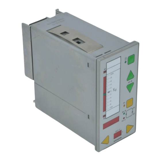
SIPART DR20 Project Planning Manual Operation and Display Functions Negative deviation display Replaceable label LED for alarm A1 LED for alarm A2 Digital display for w-x-A2-A1 and for parameters and configurations Manipulated variable adjustment in manual mode in direction of 0 % display... - Page 12 Slot AE4, unfitted, with dummy panel Slot GW, unfitted, with dummy panel Slot SES, module pulled out Terminal block of standard controller Earthing screw Mains plug Clamp for fixing the device in a panel; second clamp underneath device Fig. 2/2 Rear view of SIPART DR20...
-
Page 13: Technical Description
Technical Description Hardware The SIPART DR20 process controller is of modular design and therefore easy to service and to convert or retrofit. It consists of a standard controller in which additional option modules can be inserted to extend the functions. These option modules are inserted into slots at the rear side of the closed controller (see Fig. -
Page 14: Front Module
Project Planning Manual SIPART DR20 The standard controller comprises : • a plastic housing with clamps for installation in switchboards, panels or machines • a front module latched into this housing • a basic circuit board which can be replaced towards the rear and which contains the output stage for the K (continuous) or S (step) output and the power supply unit for various operating voltages. -
Page 15: Basic Circuit Board
SIPART DR20 Project Planning Manual All display elements are designed using LEDs thus ensuring a high service life and intensity and a good viewing angle. The individual segments are driven in TDM mode. The control elements are pushbuttons with a short travel, clear point of contact and high resetting force. They are activated through the foil via a flexible switching board designed such that the foil cannot be over-stressed. -
Page 16: Additional Modules (Options)
Project Planning Manual SIPART DR20 3.1.3 Additional Modules (Options) 3.1.3.1 Analog Inputs AE 3 and AE 4 As already mentioned and shown in Fig. 3/1, the standard controller can be equipped with two additional input modules. Definition of the functions and all other programming are described in Section 3.2. - Page 17 3.1.3.3 Serial Interface (SES) 6DR2803-8A Interface module to connect the SIPART DR20 to a serial data bus. The levels of this data bus are based on V.28; switching to V.28 point-to-point communication is possible using a jumper. Using this module, the device can transmit and receive process variables, operating states, parameter settings and configuring switch positions.
-
Page 18: Software
SIPART DR20 Software The program of the SIPART DR20 operates with a fixed cycle time of 100 ms. A process image is generated at the start of each routine. The analog and digital inputs and actions on the front keys are acquired and the process variables transferred which are received from the serial interface. - Page 19 SIPART DR20 Project Planning Manual Structuring Structuring switches Function switches Function positions positions Allocation of the analog inputs to the auxiliary Device type controlled variable X2/command variable X2 Fixed setpoint controller (ratio control) or remote setpoint WE: Fixed setpoint controller with disturbance...
- Page 20 Project Planning Manual SIPART DR20 Structuring Structuring switches Function switches Function positions positions Priority N (DDC), BL or H: Decimal point in display 4 for SP-PV-A2-A1 (ineffective with S1=7 and 8) N (DDC), BL x. x Manual mode with transmitter fault (S11): x.
- Page 21 SIPART DR20 Project Planning Manual Structuring Structuring switches Function switches Function positions positions Minimum control pulse length te Serial interface, only in conjunction with optional (only with S2 = 2 or 3) module 6DR2803-8A: 20 ms Without; controller transmits all variables, receives...
-
Page 22: Input Signal Processing
Project Planning Manual SIPART DR20 3.2.1 Input Signal Processing (Figs. 3/2 and 3/3) Analog-to-digital conversion is carried out using a quasi-integrating measurement. All analog inputs are converted approximately 120 times within 20 or 16.67 ms and the results averaged so that the mains frequency and its harmonics can be filtered out. - Page 23 SIPART DR20 Project Planning Manual Transmitter monitoring: The measured values processed in this manner can be assigned to the monitoring circuit using configuring switch S11. If one or more of the monitored variables violates the limits of -3 or +103 %, the following is monitored on the four-digit display: " 1", " 2" or " Y". This message remains until acknowledged using the pushbutton 8 (Fig.
- Page 24 Project Planning Manual SIPART DR20 Configuring switch Function of digital input position of S15 Tracking of output. In the K controller and two- position controller, the output stage is isolated from the control algorithm by this signal and directly connected to the input yN.
-
Page 25: Input Signal Processing And Switchover
SIPART DR20 Project Planning Manual The device is switched to local mode with configuring switch positions 6 to 11, a CB switchover from 0 to 1 and with front switch 13 in position "Remote". The computer coupling is only achieved again by manual switching back to remote mode. - Page 26 Project Planning Manual SIPART DR20 General, repeatedly encountered functions: Manual setpoint input w or setpoint ratio w The setpoint wi can be adjusted using the push buttons (12) in the controller types with a facility for local setpoint adjustment providing the green LED next to the local/remote selector (13) indicates "Iocal mode"...
- Page 27 SIPART DR20 Project Planning Manual The alarms A1 and A2 are indicated on the four-digit display (4) in the same engineering units as the setpoint and actual value. The hysteresis is 1 % of the measuring range. Caution: In addition to monitoring on the instrument, alarm signals can also be output externally using an additional module (page 80).
- Page 28 Project Planning Manual SIPART DR20 8 8 8 SP - w S20, S21 8 8 8 4 Display 8 8 8 8 x - tracking A = H or N or Bl or Si Fig. 3/4 Processing of command variable and formation of the negative deviation with a fixed setpoint controller •...
- Page 29 SIPART DR20 Project Planning Manual 8 8 8 SP - w x - tracking S20, S21 D-element (S27) 8 8 8 4 Display see Fig. 3/19 8 8 8 8 X1 + c1 + c2 ∗ X2 A = H or N or Bl or Si Fig.
- Page 30 Project Planning Manual SIPART DR20 Si v Bl Si v Bl 8 8 8 Si v Bl SP - w S20, S21 Display S19=1 8 8 8 4 8 8 8 8 is not used D-element x - tracking Fig. 3/6...
- Page 31 SIPART DR20 Project Planning Manual Control commands Signals Effec- Effective setpoint front and digital tive S19=0 Explanations inputs **) output Front Digital LED ***) output H Si S17=0 S18=0 yE(n) *) DDC mode autom. mode prepared yE(n) *) DDC mode...
- Page 32 Project Planning Manual SIPART DR20 Programming according to the following Fig. 3/8 is used if automatic mode is to be selected directly following computer failure. Control commands Signals Effec- Effective setpoint front and digital tive S19=0 Explanations inputs **) output...
- Page 33 This type of device is for use as a follow-up controller in a cascade or for remote setpoint control of the SIPART DR20. In the case of a cascade control, the follow-up controller can only be separated from the master controller by switching the latter to manual mode.
- Page 34 Project Planning Manual SIPART DR20 • S1 = 5 Follow-up controller with local/remote switch over (Fig. 3/13) This controller type is suitable for SPC mode and operation with two or three setpoints (wi, wE, wS). The remote setpoint can be entered either via an analog input as a variable wE or via the serial interface as wES.
- Page 35 From software version A06 onwards it is also possible to set two different setpoints on the front of the SIPART DR20 and to select one of the values by switching over or by using a setpoint ramp. Settings required when used as:...
- Page 36 Project Planning Manual SIPART DR20 Selector key 8 Output in display 4 Signalling by Position 1 LED 9.1 Position 2 LED 9.2 Position 3 "A2" in display 6 Position 4 "A1" in display 6 Position 5 "SH" in display 6...
- Page 37 SIPART DR20 Project Planning Manual • S1 = 6 Synchronization controller without local/remote switchover (Fig.3/14) In the case of synchronization control, a common command variable is applied to several control loops. The command variable can be shifted by the constant c1 and apportioned with the factor c2 in each controller individually.
- Page 38 Project Planning Manual SIPART DR20 In the following, the defined (adjustable using the pushbuttons 12) ratio factor is referred to as the setpoint ratio w and indicated as the setpoint on the digital display. The range of adjustment of the...
- Page 39 SIPART DR20 Project Planning Manual Ratio factor Wv = 0,4 to 1,0 Ratio factor Wv = 0,5 to 1,5 Basic value 20% = c1 = 0,2 Ratio factor Wv = 0,4 to 0,7 Basic value - 15% = c1 = - 0,15...
- Page 40 When configuring the digital input with the CB function or when operating via the serial interface, the SIPART DR20 can also be used as a DDC manual control station in this mode. The manipulated variable is made to track yN or yES during DDC mode with a K output, with an S output / two-position controller and only yES with an S output / three-position step controller with external feedback of the manipulated variable.
- Page 41 SIPART DR20 Project Planning Manual Switchover of the output, is as with the DDC controller. "Automatic mode" with the DDC manual control station causes the manipulated variable to be held constant by the connection yA = y'. (Details on the output structures are shown in Section 3.2.4).
- Page 42 Project Planning Manual SIPART DR20 The variable applied to input x1 is indicated as the actual value x. The limit monitors A1/A2 can be configured to the mentioned variables. The two-digit display can also indicate a further process variable in %. The associated input signal is yR / yN.
-
Page 43: Control Algorithm
SIPART DR20 Project Planning Manual 3.2.3 Control Algorithm This section describes the following functions: − Filtering of negative deviation xd − Display of negative deviation − Response threshold of negative deviation − Matching to direction of action − D element −... - Page 44 Project Planning Manual SIPART DR20 The rear of the label is unprinted and can be used for any divisions, including engineering units. A dimensional drawing of the scale label and information on a suitable labelling unit are included in the operating instructions.
- Page 45 SIPART DR20 Project Planning Manual Matching to direction of action: The basic setting of the controller applies to systems with a normal action. In the case of reversed systems, the sign of the proportional gain Kp can be inverted using configuring switch S26. As can be seen in Fig.
-
Page 46: Output Signal Processing And Switchover
Project Planning Manual SIPART DR20 Limitation of controller output signal yA: (only possible with K controllers and three-position step controllers with external position feedback, i.e. with S2 = 0 and S2 = 3) Manipulated variable limitation with parameters ya and ye is only possible in automatic mode. The limits of these parameters are -10 and + 110 %. - Page 47 SIPART DR20 Project Planning Manual General, recurring functions : Possible operating modes: (The optical signals are shown in Section 3.2.6) • Automatic operation with y = yA. This mode can be interrupted by digital signals (see also page 23) as well as by manual interventions.
- Page 48 Project Planning Manual SIPART DR20 Priority switchover of manual and tracking mode/blocking: It is possible to define the priority for all controllers with internal position feedback using configuring switch S29. S29 = 0 The digital functions N and BL have priority over manual switchover to manual operation.
- Page 49 + ∆y and - ∆y are driven. Function and direction of action of digital output: The SIPART DR20 has a digital output (see Fig. 3/3, page 25) which can be assigned to an operating mode or transmitter fault signal (S34) and whose NC or NO position can be inverted using S35.
- Page 50 Project Planning Manual SIPART DR20 Control commands Status Signals Effective front and digital output Explanations inputs Front Digital output N *) Automatic mode Tracking mode Blocking mode Blocking mode Manual mode Tracking mode Blocking mode Blocking mode Safety mode Safety mode Fig.
- Page 51 SIPART DR20 Project Planning Manual Functions depending on the possible output configurations: • S2 = 0 K output (Figs. 3/24 and 3/25) With a K controller the resulting manipulated variable y is output as a current Iy. S37 can be used to set the range to 0 or 4 to 20 mA.
- Page 52 Project Planning Manual SIPART DR20 MuSt N + DDC DDC = RC = INT ∗ CB Fig. 3/25 Output configuration of K controller, tracking mode/blocking has priority over manual mode • S2 = 1 Output configuration as S two-position controller with two outputs (heating/cooling) (Figs.
- Page 53 SIPART DR20 Project Planning Manual In section y = 0 % to ya (cooling) the period is set using T- and the associated output is -∆y. The control ratio is then from 1 at y = 0 % at y = ya.
- Page 54 Project Planning Manual SIPART DR20 Caution: The parameters ya and ye are used with other output configurations to define the limits of the manipulated variable. For this reason the factory settings are ya = 0 % and ye = 100 %. It is therefore essential to reset these parameters since the device cannot output a manipulated variable signal with this output configuration.
- Page 55 SIPART DR20 Project Planning Manual • S2 = 2 S three-position step output for motor-driven actuators with internal position feedback (Figs. 3/30, 3/31) With this type of controller, an internally simulated position control loop is connected to the PID control algorithm. The integral response of the final control element is simulated by an integrator with an adjustable positioning time (parameter Ty) which replaces the position feedback.
- Page 56 Project Planning Manual SIPART DR20 MuSt > 50% - ∆y < 50% Bl + DDC + ∆y DDC = RC = INT ∗ CB Fig. 3/31 Output configuration of three-position step controller with internal position feedback, blocking has priority over manual mode •...
- Page 57 SIPART DR20 Project Planning Manual MuSt - ∆y + ∆y N + DDC Fig.3/32 Output configuration of three-position step controller with external position feedback, tracking mode/blocking has priority over manual mode MuSt - ∆y + ∆y N + DDC DDC = RC = INT ∗ CB Fig.
-
Page 58: Restart Conditions
4 (see page 21). The SIPART DR20 does not start with the last operating states since these cannot be transferred fast enough to the non-volatile memory in the case of a power failure. However, the local setpoint wi is loaded into the EEPROM if it has not been changed for approx. - Page 59 SIPART DR20 Project Planning Manual Cofiguring S1 = 0, 1, 2, 7, 8 S1 = 5, 10 S1 = 3, 9 switch Selected /INT /INT /INT function w -adjust- local remote local controller ment mode mode/SPC mode backup mode blocked...
-
Page 60: Bus Interface
These are then followed, if applicable, by the data to be received. If the message is received without faults, the SIPART DR20 replies immediately with a message with exactly the same format: STX, station number, data, ETX and, if applicable, cross-check sum. The data section is omitted because no values are requested. - Page 61 SIPART DR20 Project Planning Manual All received information of a message is first stored in a receiver register with max. 32 byte and checked for faults. Fault-free messages are processed further as input signals at the start of the following arithmetic cycle. The transfer of modified parameter and configuring switch positions to the non-volatile EEPROM requires several seconds, however.
-
Page 62: Technical Data
Project Planning Manual SIPART DR20 Technical Data General data: Mounting position Permissible ambient temperature Operation 0 to 50 °C Transport and storage - 25 to + 75 °C Humidity class F to DIN 40040 Degree of protection Front IP 64 to DIN 40050... - Page 63 SIPART DR20 Project Planning Manual Number of Cut-out devices width b 140 + 1 212 + 1 284 + 1 716 +1 Mounting depth required to replace the signal converters But mounting above each other is permissible within the permissible ambient temperature range Fig.
- Page 64 Project Planning Manual SIPART DR20 • Power supply Rated voltage AC 220/230/240 V AC 110/115/120 V UC 24 V Operating voltage range AC 195 to 276 V AC 97 to 138 V AC 20 to 28 V DC 20 to 35 V...
- Page 65 SIPART DR20 Project Planning Manual • Digital output BA (with wired-OR diodes) ≤ 1.5 V Signal state "0" Signal state" 1" + 19 to + 26 V Max. load current 30 mA, short-circuit-proof Short-circuit current < 200 mA, pulsed Static destruction limit - 1 V / + 35 V ±...
- Page 66 Project Planning Manual SIPART DR20 • CPU data 97.8 ms ± 1 % Controller cycle time Smallest integration rate dy/dt = Kp ∗ xd / Tn 0.1 ∗ 0.1. % / 10 • A/D conversion Procedure Successive approximation, > 120 conversions per input and averaging over 20 or 16.67 ms...
- Page 67 SIPART DR20 Project Planning Manual • Option modules Signal converter for Current Voltage Resistance Resistance Thermocouple, transmitter thermometer Order No. 6DR2800-8J 6DR2800-8J 6DR2800-8R 6DR2800-8P 6DR2800-8T 0 Ω ≥ 80.25 Ω Start-of-scale value 0 / 4 mA 0 / 2 V - 5∆U…0…+ 5∆U...
- Page 68 Project Planning Manual SIPART DR20 • Alarm module with relays (6DR2801-8A) Contact material AG-Ni Contact loading capacity Alternating current Direct current Max. switching voltage AC 35 V DC 35 V Max. switching current Max. switching power 150 VA 100 W at 24 V...
- Page 69 SIPART DR20 Project Planning Manual • Serial interface (6DR2803-8A) Communication signals V.24 / V.28 signals to CCITT - V.24 Transferable data Operational status, process variables, parameters and configuring switches Communications procedure to DIN 66258 A or B Character format 10 bits (start bit, ASCII character with 7 bit,...
-
Page 70: Mounting
The front and rear of the controller must be readily accessible. Panel mounting: SIPART DR20 controllers are fitted either in individual panel cutouts or in open tiers (dimensional drawing 4/2 on page 63). In order to ensure adequate interference suppression, even at high frequencies, we recommend that the paint be removed from the top edge of the panel cut-out. -
Page 71: Wiring
Zero volt system: The SIPART DR20 controller has just one zero-volt conductor M at the field end which is lead out twice to terminals 6 and 7 of the standard controller. All input and output signals refer to this point. - Page 72 Project Planning Manual SIPART DR20 Fig. 5/1 SES and bus driver int erfaces AE 1 / AE 2 0 (4) to + 20 mA 249 Ω Connection circuit of AE1 or AE2 with a non-floating current source AE 1 / AE 2 0 (4) to + 20 mA 249 Ω...
- Page 73 500 Ω between AE - and M (see Fig. 5/3). The negative terminal of the transmitter circuit must be connected to M. Note with two-wire transmitters and with power supply from the SIPART DR20 that the additional external loads correspondingly reduce the supply voltage available to the transmitter.
- Page 74 Project Planning Manual SIPART DR20 4 to 20 mA AE + AE3 / AE4 49.9 Ω Ι AE - 6DR2800-8J Standard controller Connection of a two-wire transmitter to a signal converter 6DR2800-8J. The transmitter is powered by L+ of the controller:...
- Page 75 SIPART DR20 Project Planning Manual 0 to + 10 V AE + AE3 / AE4 49.9 Ω AE - 6DR2800-8J Standard controller Connection circuit of signal converter 6DR2800-8J as voltage input for a non-floating voltage source of 0 to +10 V. The possible drop on the M bar enters the measurement as an error.
- Page 76 Project Planning Manual SIPART DR20 6DR2800-8R see wiring diagram, Fig. 5/6 Potentiometers with rated values from 80 to 1200 Ω can be connected as resistance transmitters. A constant current of 5 mA is applied to the wiper of the potentiometer. Resistors are connected in parallel to the potentiometer by means of a slide switch on the module in order to carry out coarse selection of the measuring range.
- Page 77 SIPART DR20 Project Planning Manual R Ω Ω ∆R Ω 79.3 - 82.4 GH GH GH GH GH GH GH 199.3 - 202.4 GH GH GH GH GH G 18.4 - 19.6 KL KL 81.3 - 84.4 GH GH GH GH GH GH G 201.3 - 204.4...
- Page 78 (welded-on, earthed in undefined manner) can also be connected if two SIPART DR20 controllers are provided with a thermocouple input and connected together via the ground lead. If this is not the case, it is recommendable to connect terminal 3 to M (terminal 6 of standard controller).
- Page 79 20.0 BC AB AB AB A breakage. Tables with the required jumper settings are included in 19.6 - 20.6 BC AB AB A the SIPART DR20 instructions. 20.3 - 21.3 AB BC A 21.2 - 22.5 AB AB BC BC A Fine adjustment of the measuring range (start-of-scale value and 22.0 -...
- Page 80 Project Planning Manual SIPART DR20 Optional modules for alarm monitoring Please refer to the note on signalling on page 27. 6DR2801-8A see connection diagram, Fig. 5/9 This module is equipped with two relays for external signalling of the alarms A1/A2. The contact configuration can be set according to the connection diagram using soldered jumpers on the module.
- Page 81 SIPART DR20 Project Planning Manual + ∆y 3 / 5 24 V - ∆y 3 / 4 24 V 3 / 3 ≥ 17.5 V ≤ 30 mA 24 V 3 / 2 24 V BLPS 3 / 1 24 V...
- Page 82 Project Planning Manual SIPART DR20 • SIPART Bus Fig. 5/12 SES / bus driver / remote system wiring diagram...
- Page 83 SIPART DR20 Project Planning Manual SIPART bus wiring principles Fig. 5/13 Wiring of SES bus driver to SIPART bus marshalling SES on bus (x1 = x2)
- Page 84 Project Planning Manual SIPART DR20 Bus driver C73451-A347-B202 wiring principles and interface to remote system Fig. 5/14 V.28 point-to-point to a remote system with no isolation between the SIPART bus and the remote system Fig. 5/15 V.28 point-to-point to a remote system with the SIPART bus and the remote system...
- Page 85 SIPART DR20 Project Planning Manual Fig. 5/16 TTY to remote system with SIPART bus and remote system isolated. Txd on the remote system is an active current source that is not isolated from Rxd. Fig. 5/17 TTY to remote system with the SIPART bus and the remote system isolated.
- Page 86 Project Planning Manual SIPART DR20 Fig.5/18 TTY to remote system with the SIPART bus and the remote system isolated. Txd on the remote system is a passive switch, Txd and Rxd are isolated.
-
Page 87: Adjustments And Operation
SIPART DR20 Project Planning Manual Adjustment and Operation Operation of the SIPART DR20 controller is carried out at three modes: • Process operation • Parameterization • Configuring The pushbuttons and displays on the front of the controller sometimes have different functions in these three modes. -
Page 88: Parameterization
The following Sections 6.2 and 6.3 describe the parameterization and configuring of the SIPART DR20. Please note that all settings in these modes are stored in the RAM. The transfer into the fail-safe EEPROM only takes place after return to process operation mode and requires a few seconds. -
Page 89: Configuring
SIPART DR20 Project Planning Manual Press selector 8 until the two-digit display 6 outputs "PS" (flashing). Release push-button; the display "PS" becomes steady. The two digital displays no longer indicate any process variables. The controller is still fully functional and indicates the negative deviation xd. - Page 90 Project Planning Manual SIPART DR20 Parameter Char- Display Min. Max. Factory Dim. Remarks acter on (6) value value setting Derivative-action gain “uu” 1.00 10.0 5.00 Proportional gain “cP” 0.100 100.0 0.100 Reset time “tn” 9984 9984 With PI controller S28 = 0 Working point “Yo”...
-
Page 91: Lamp Test
Display of Software Release In accordance with the technical developments of our products, the SIPART DR20 software is matched to new knowledge as required. The software release is stored in a number (A..) in the PROM and can be called as follows: Press pushbutton 8 until lamp test is carried out. - Page 92 Project Planning Manual SIPART DR20 In the case of highly arced curves, it may be advantageous to improve the approximation by not applying the corner points of the polygon curve exactly on the function (but exactly on the division by 8 of the electric axis). The physical values associated with the turning points must then be entered as parameters L1 to L7.
-
Page 93: Standard Measuring Ranges For Temperature
SIPART DR20 Project Planning Manual Factory setting of configuring switches: the factory setting of the configuring switches is always "0", i.e. also with the S controller where it is essential to reset certain switches (e.g. S2). It is therefore always recommendable to check the compatibility of the settings with the desired operating mode. - Page 94 Project Planning Manual SIPART DR20 Marshalling Parametrization ∆U Measuring Linearization range Type Value Cu - CuNi 0 - 300 °C AB A BC A 88 127 164 200 234 268 300 0 - 400 °C AB BC A 63 120 172 221 268 314 357 400 200 - 400 °C...
-
Page 95: Matching To Direction Of Action
SIPART DR20 Project Planning Manual Commissioning Most of the configuring switches and a number of parameters can already be set prior to actual commissioning. Because of missing data and unclear relationships, the remaining ones can only be determined in the system itself by "systematic trial-and-error". The following sections should be... -
Page 96: Matching Of Step Controllers To Final Control Elements
Project Planning Manual SIPART DR20 Matching of Step Controllers to Final Control Elements 7.2.1 Two-Position Controller (S2 = 1) The division into two zones (e.g. heating and cooling) or only one zone (only heating or only cooling) using parameters ya and ye has already been described on pages 52/53. In addition, the parameters T+ and T- must be matched to the period of the units connected to + ∆y and - ∆y. -
Page 97: Optimization Guidelines
SIPART DR20 Project Planning Manual • The response threshold (parameter A) must be set according to the set te and the resulting ∆y or ∆x. The condition ∆x Ks ∗ te ∗ 100 % A > ------- A > --------------------- 2 ∗... - Page 98 Project Planning Manual SIPART DR20 • PD controller (S28 = 1) - Adjust the desired setpoint and control the negative deviation to zero in manual mode. In position "AUTO" of parameter yo, the working point required for a negative deviation of zero is set automatically in the process.
- Page 99 SIPART DR20 Project Planning Manual 7.3.2 Adjustment of Control Parameters According to Transient Function If the transient function of the controlled system is known or can be determined using a recorder, the control parameters can be set according to guidelines found in the technical literature. The transient function of the system can be recorded in manual mode by suddenly changing the manipulated variable and recording the controlled variable with respect to time.
-
Page 100: Abbreviations
Project Planning Manual SIPART DR20 The dead zone element provides the controller with a progressive response; the gain is small or even zero in the case of small negative deviations, the defined Kp is reached with large negative deviations. The factory setting of A is 0. A setting must be made for three-position step controllers (see page 89). -
Page 101: Ordering Data
4-way for thermocouple input module C73451-A3000-B17 Terminal block 5-way for alarm module W73078-B5-A905 Plug for ribbon cable (interface) C73451-A347-D36 Scale for SIPART DR20 (front side printed ~ 10%) C73451-A3000-C21 Blank scale for SIPART DR20 C73451-A3000-C22 Included in scope of deliveries... - Page 102 An important requirement for the safe control of process engineering plants is reliable monitoring. Therefore the functions provided by modern process control systems include central operation and monitoring using monitors. This possibility can also be implemented with the Siemens digital compact controllers.
-
Page 103: Representation Of Various Setpoints
SIPART DR20 Project Planning Manual Representation of Various Setpoints The following pages contain functional diagrams which show how the setpoints change with respect to time if • the local / remote pushbutton (13) on the front panel is pressed •... - Page 104 Project Planning Manual SIPART DR20 w (%) S 1 = 0 S 15 = 1 S 16 = 0 S 17 = 1 S 19 = 1 Si = 1 Si = 0 Fig. 11/2 Setpoint response according to example 2...
- Page 105 SIPART DR20 Project Planning Manual Example 4: Two-setpoint mode according to configuration described on page 33. Both setpoints can be called into the four-digit display using pushbutton 8 and adjusted using pushbutton 12 on the front of the controller. The switch over between w1 (safety setpoint wS) and w2 (local setpoint wi) is carried out by the local/remote switch 13.
- Page 106 Project Planning Manual SIPART DR20 Example 6: Three-setpoint mode with one follow-up controller where the following variables can be used: is a remote setpoint wE is the safety setpoint wS fixed by parameterization is the local setpoint wi adjustable on the front Switchover between w1 and w2 is carried out using the digital signal CB (local / remote pushbutton 13 must be at "Remote").
- Page 107 SIPART DR20 Project Planning Manual Example 7: Four-setpoint mode with one follow-up controller with local / remote switchover and CB signal via the digital input. The controller is fitted with an optional module 6DR2800-8J as a voltage input. The four setpoints can be...
-
Page 108: Planning Examples
All possible input circuits are shown. Please note in the case of a power supply to a two-wire transmitter from the SIPART DR20 and simultaneous use of the analog inputs AE1 / AE2 that the supply voltage for the transmitter may be only DC 15 V in an unfavourable case (see page 73). - Page 109 S28 (= 1). If this is necessary. it is essential to connect an electronic position transmitter (EPT) via yR in the case of a SIPART DR20 with S output and to set configuring switch S2 = 3.
- Page 110 Project Planning Manual SIPART DR20 List of planning examples Page Fixed setpoint controller, controlled variable from four-wire transmitter, position feedback from electronic position transmitter (EPT) Fixed setpoint controller, controlled variable direct from thermocouple (internal cold junction), position feedback from electronic position transmitter...
- Page 111 SIPART DR20 Project Planning Manual Empty page...
- Page 112 ⎭ ⎫ AC 115 V ⎬ AC 230 V ⎭ Slot 3 Slot 2 Slot 1 SIPART DR20 K 6DR2004-1 (AC 230 V) 6DR2004-2 (AC 115 V) Option module not equipped not equipped 6DR2004-4 (UC 24 V) 6DR2801-8A GND GND...
- Page 113 ⎭ ⎫ AC 115 V ⎬ AC 230 V ⎭ Slot 3 Slot 2 Slot 1 SIPART DR20 K 6DR2004-1 (AC 230 V) 6DR2004-2 (AC 115 V) Option module not equipped not equipped 6DR2004-4 (UC 24 V) 6DR2801-8A GND GND...
- Page 114 ⎭ ⎫ AC 115 V ⎬ AC 230 V ⎭ Slot 3 Slot 2 Slot 1 SIPART DR20 K 6DR2004-1 (AC 230 V) 6DR2004-2 (AC 115 V) Option module Option module not equipped 6DR2004-4 (UC 24 V) 6DR2801-8A 6DR2800-8P GND GND Line resistances ≤...
- Page 115 ⎭ ⎫ AC 115 V ⎬ AC 230 V ⎭ Slot 3 Slot 2 Slot 1 SIPART DR20 K 6DR2004-1 (AC 230 V) 6DR2004-2 (AC 115 V) Option module Option module not equipped 6DR2004-4 (UC 24 V) 6DR2801-8A 6DR2800-8P GND GND Line resistances ≤...
- Page 116 ⎭ ⎫ AC 115 V ⎬ AC 230 V ⎭ Slot 3 Slot 2 Slot 1 SIPART DR20 K 6DR2004-1 (AC 230 V) 6DR2004-2 (AC 115 V) Option module Option module not equipped 6DR2004-4 (UC 24 V) 6DR2801-8A 6DR2800-8P GND GND Line resistances ≤...
- Page 117 ⎭ ⎫ AC 115 V ⎬ AC 230 V ⎭ Slot 3 Slot 2 Slot 1 SIPART DR20 K 6DR2004-1 (AC 230 V) 6DR2004-2 (AC 115 V) Option module Option module not equipped 6DR2004-4 (UC 24 V) 6DR2800-8T 6DR2801-8A GND GND...
- Page 118 ⎭ ⎫ AC 115 V ⎬ AC 230 V ⎭ Slot 3 Slot 2 Slot 1 SIPART DR20 K 6DR2004-1 (AC 230 V) 6DR2004-2 (AC 115 V) Option module Option module not equipped 6DR2004-4 (UC 24 V) 6DR2800-8T 6DR2801-8A GND GND...
- Page 119 ⎭ ⎫ AC 115 V ⎬ AC 230 V ⎭ Slot 3 Slot 2 Slot 1 SIPART DR20 K 6DR2004-1 (AC 230 V) 6DR2004-2 (AC 115 V) Option module Option module Option module 6DR2004-4 (UC 24 V) 6DR2800-8R 6DR2800-8T 6DR2801-8A...
- Page 120 ⎫ AC 115 V ⎬ Ratio station AC 230 V ⎭ Slot 3 Slot 2 Slot 1 SIPART DR20 K 6DR2004-1 (AC 230 V) 6DR2004-2 (AC 115 V) Option module Option module not equipped 6DR2004-4 (UC 24 V) 6DR2801-8A 6DR2800-8J...
- Page 121 AC 115 V ⎬ Slave controller AC 230 V ⎭ Slot 3 Slot 2 Slot 1 SIPART DR20 K 6DR2004-1 (AC 230 V) 6DR2004-2 (AC 115 V) Option module not equipped not equipped 6DR2004-4 (UC 24 V) 6DR2801-8A GND GND...
- Page 122 ⎫ AC 115 V ⎬ Master controller AC 230 V ⎭ Slot 3 Slot 2 Slot 1 SIPART DR20 K 6DR2004-1 (AC 230 V) 6DR2004-2 (AC 115 V) not equipped not equipped not equipped 6DR2004-4 (UC 24 V) GND GND...
- Page 123 AC 115 V ⎬ Slave controller AC 230 V ⎭ Slot 3 Slot 2 Slot 1 SIPART DR20 K 6DR2004-1 (AC 230 V) 6DR2004-2 (AC 115 V) Option module not equipped not equipped 6DR2004-4 (UC 24 V) 6DR2801-8A GND GND...
- Page 124 ⎭ ⎫ AC 115 V ⎬ AC 230 V ⎭ Slot 3 Slot 2 Slot 1 SIPART DR20 K 6DR2004-1 (AC 230 V) 6DR2004-2 (AC 115 V) Option module not equipped not equipped 6DR2004-4 (UC 24 V) 6DR2801-8A GND GND...
- Page 125 ⎭ ⎫ AC 115 V ⎬ AC 230 V ⎭ Slot 3 Slot 2 Slot 1 SIPART DR20 S 6DR2001-1 (AC 230 V) 6DR2001-2 (AC 115 V) Option module not equipped not equipped 6DR2001-4 (UC 24 V) 6DR2801-8A GND GND -∆y +∆y...
- Page 126 ⎭ ⎫ AC 115 V ⎬ AC 230 V ⎭ Slot 3 Slot 2 Slot 1 SIPART DR20 S 6DR2001-1 (AC 230 V) 6DR2001-2 (AC 115 V) Option module Option module not equipped 6DR2001-4 (UC 24 V) 6DR2801-8A 6DR2800-8T GND GND -∆y +∆y...
- Page 127 ⎭ ⎫ AC 115 V ⎬ AC 230 V ⎭ Slot 3 Slot 2 Slot 1 SIPART DR20 S 6DR2001-1 (AC 230 V) 6DR2001-2 (AC 115 V) Option module Option module Option module 6DR2001-4 (UC 24 V) 6DR2801-8A 6DR2800-8R 6DR2800-8P GND GND -∆y +∆y...
- Page 128 UC 24 V ⎭ ⎫ AC 115 V ⎬ AC 230 V ⎭ Slot 3 Slot 2 Slot 1 SIPART DR20 S 6DR2001-1 (AC 230 V) 6DR2001-2 (AC 115 V) Option module Option module not equipped 6DR2001-4 (UC 24 V) 6DR2801-8A 6DR2800-8P GND GND -∆y +∆y...
- Page 129 ⎭ ⎫ AC 115 V ⎬ AC 230 V ⎭ Slot 3 Slot 2 Slot 1 SIPART DR20 S 6DR2001-1 (AC 230 V) 6DR2001-2 (AC 115 V) Option module Option module Option module 6DR2001-4 (UC 24 V) 6DR2801-8A 6DR2800-8R 6DR2800-8P GND GND -∆y +∆y...
- Page 130 AC 115 V ⎬ AC 230 V ⎭ Master controller Slot 3 Slot 2 Slot 1 SIPART DR20 K 6DR2004-1 (AC 230 V) 6DR2004-2 (AC 115 V) Option module not equipped not equipped 6DR2004-4 (UC 24 V) 6DR2800-8P GND GND ≤...
- Page 131 ⎫ AC 115 V ⎬ AC 230 V ⎭ Slave controller Slot 3 Slot 2 Slot 1 SIPART DR20 S 6DR2001-1 (AC 230 V) 6DR2001-2 (AC 115 V) Option module Option module Option module 6DR2001-4 (UC 24 V) 6DR2801-8A 6DR2801-8R...
- Page 132 ⎭ ⎫ AC 115 V ⎬ AC 230 V ⎭ Slot 3 Slot 2 Slot 1 SIPART DR20 S 6DR2001-1 (AC 230 V) 6DR2001-2 (AC 115 V) Option module Option module not equipped ! 6DR2001-4 (UC 24 V) 6DR2801-8A 6DR2801-8R GND GND -∆y +∆y...
- Page 133 ⎭ ⎫ AC 115 V ⎬ AC 230 V ⎭ Slot 3 Slot 2 Slot 1 SIPART DR20 S 6DR2001-1 (AC 230 V) 6DR2001-2 (AC 115 V) Option module Option module not equipped ! 6DR2801-8A 6DR2800-8T 6DR2001-4 (UC 24 V) −...
- Page 134 Circuit diagram ⎫ ⎬ UC 24 V ⎭ ⎫ AC 115 V ⎬ AC 230 V ⎭ Slot 3 Slot 2 Slot 1 SIPART DR20 K 6DR2004-1 (AC 230 V) 6DR2004-2 (AC 115 V) 6DR2004-4 (UC 24 V) GND GND...
- Page 135 ⎫ ⎬ UC 24 V ⎭ ⎫ AC 115 V ⎬ AC 230 V ⎭ Slot 3 Slot 2 Slot 1 SIPART DR20 S 6DR2001-1 (AC 230 V) 6DR2001-2 (AC 115 V) 6DR2001-4 (UC 24 V) GND GND -∆y +∆y...
- Page 136 Project Planning Manual SIPART DR20 Setting of SIPART -Controller No. / Tag-No. ………………………………………. Configuring Parameterization Strs Setting Parameter Dis- Setting play Derivative-action gain Proportional gain Reset time Working point Derivative-action time Filter time constant for xd Setpoint ramp Valve positioning time...
Need help?
Do you have a question about the SIPART DR20 and is the answer not in the manual?
Questions and answers