Table of Contents
Advertisement
SIMOTION
SIMOTION D410-2
Commissioning and Hardware Installation Manual
Valid for SIMOTION D410-2 DP and D410-2 DP/PN as
of Version 4.4
01/2015
Preface
Safety instructions
Description
Installing
Connecting
Commissioning (hardware)
Parameter assignment /
addressing
Commissioning (software)
Service and maintenance
Diagnostics
Configuring drive-related I/
Os (without symbolic
assignment)
Standards and approvals
ESD guidelines
1
2
3
4
5
6
7
8
9
A
B
C
Advertisement
Table of Contents

Related Manuals for Siemens SIMOTION D410-2DP/PN


Summary of Contents for Siemens SIMOTION D410-2DP/PN
- Page 1 Preface Safety instructions Description SIMOTION Installing SIMOTION D410-2 Connecting Commissioning (hardware) Commissioning and Hardware Installation Manual Parameter assignment / addressing Commissioning (software) Service and maintenance Diagnostics Configuring drive-related I/ Os (without symbolic assignment) Standards and approvals ESD guidelines Valid for SIMOTION D410-2 DP and D410-2 DP/PN as of Version 4.4 01/2015...
- Page 2 Note the following: WARNING Siemens products may only be used for the applications described in the catalog and in the relevant technical documentation. If products and components from other manufacturers are used, these must be recommended or approved by Siemens. Proper transport, storage, installation, assembly, commissioning, operation and maintenance are required to ensure that the products operate safely and without any problems.
-
Page 3: Preface
Preface Contents of the Commissioning and Hardware Installation Manual This document is part of the SIMOTION D documentation package. Scope The SIMOTION D410‑2 Commissioning and Hardware Installation Manual describes the commissioning and installation of the SIMOTION D410‑2 DP and SIMOTION D410‑2 DP/PN control units. - Page 4 My Documentation Manager Click the following link for information on how to compile documentation individually on the basis of Siemens content and how to adapt it for the purpose of your own machine documentation: SIMOTION D410-2 Commissioning and Hardware Installation Manual, 01/2015...
- Page 5 Preface http://www.siemens.com/mdm Training Click the following link for information on SITRAIN - Siemens training courses for automation products, systems and solutions: http://www.siemens.com/sitrain FAQs Frequently Asked Questions can be found in SIMOTION Utilities & Applications, which are included in the scope of delivery of SIMOTION SCOUT, and in the Service&Support pages in Product Support: http://support.automation.siemens.com...
- Page 6 SIMOTION SCOUT scope of delivery and, along with FAQs, also contain free utilities (e.g. calculation tools, optimization tools, etc.) as well as application examples (ready-to- apply solutions such as winders, cross cutters or handling) ● The latest SIMOTION FAQs at http://support.automation.siemens.com/WW/view/en/ 10805436/133000 ● SIMOTION SCOUT online help Overview of SIMOTION documentation (separate ●...
-
Page 7: Table Of Contents
Table of contents Preface.................................3 Safety instructions............................13 Fundamental safety instructions....................13 1.1.1 General safety instructions.....................13 1.1.2 Safety instructions for electromagnetic fields (EMF)..............16 1.1.3 Handling electrostatic sensitive devices (ESD)..............16 1.1.4 Industrial security........................17 1.1.5 Residual risks of power drive systems...................18 Specific safety information for SIMOTION D410-2..............21 Description..............................23 System overview........................23 System components.......................28... - Page 8 Table of contents 4.8.6 Connection rules in the PROFIBUS subnet................64 4.8.7 Operating interface X21 as an MPI..................66 Connecting PROFINET IO components (D410-2 DP/PN only)..........69 4.9.1 Wiring PROFINET........................69 4.9.2 PROFINET cables and connectors..................69 4.10 Connecting Ethernet......................72 4.11 Routing...........................74 4.11.1 Routing on SIMOTION D.......................74 4.11.2 Routing on SIMOTION D (SINAMICS integrated)..............77 4.12...
- Page 9 Table of contents Configuring PROFINET IO....................124 6.5.1 General information about communication via PROFINET IO..........124 6.5.2 Setting a send cycle clock and system cycle clocks............128 6.5.3 Properties of PROFINET......................130 6.5.4 Configuration tasks......................131 6.5.5 Rules for cycle clock settings with SIMOTION D410-2 DP/PN..........131 Configuring an Ethernet subnet...................134 6.6.1 General information about communication via Ethernet............134...
- Page 10 Table of contents 7.7.1 Setting up communication for symbolic assignment............195 7.7.2 Message frame configuration....................195 Linking an additional encoder (optional)................199 7.8.1 General information......................199 7.8.2 Configuring additional encoders on the drive...............200 7.8.3 Connecting additional encoders via PROFIBUS/PROFINET..........201 Symbolic assignment of I/O variables..................202 7.9.1 Assignment to the PROFIdrive message frame of the TO axis ..........202 7.9.2...
- Page 11 Table of contents 7.21 Migration from SIMOTION D410 to SIMOTION D410-2............250 7.21.1 Upgrade from SIMOTION D410 to SIMOTION D410-2............250 7.21.2 Permissible combinations....................252 7.21.3 CompactFlash card and license combinations..............253 7.22 Special functions SIMOTION D410-2..................255 7.22.1 Automatic restart after FAULT state..................255 7.22.2 Triggering a restart with a user program................256 Service and maintenance.........................259 Overview..........................259...
- Page 12 Table of contents 9.2.1 Overview..........................304 9.2.2 Backup of diagnostic data and non-volatile SIMOTION data..........304 9.2.2.1 Diagnostics data........................304 9.2.2.2 Non-volatile SIMOTION data (retain data)................305 9.2.3 Save diagnostic data during running operation..............305 9.2.4 Save diagnostic data during the startup................306 9.2.5 Storing the diagnostic data and non-volatile SIMOTION data..........308 9.2.6 Diagnostics via websites......................309 9.2.7...
-
Page 13: Safety Instructions
Safety instructions Fundamental safety instructions 1.1.1 General safety instructions DANGER Danger to life due to live parts and other energy sources Death or serious injury can result when live parts are touched. ● Only work on electrical devices when you are qualified for this job. ●... - Page 14 Safety instructions 1.1 Fundamental safety instructions WARNING Danger to life from touching live parts on damaged devices Improper handling of devices can result in damage. For damaged devices, hazardous voltages can be present at the enclosure or at exposed components; if touched, this can result in death or severe injury. ●...
- Page 15 Safety instructions 1.1 Fundamental safety instructions WARNING Danger to life from unexpected movement of machines when using mobile wireless devices or mobile phones Using mobile radios or mobile phones with a transmit power > 1 W closer than approx. 2 m to the components may cause the devices to malfunction, influence the functional safety of machines therefore putting people at risk or causing material damage.
-
Page 16: Safety Instructions For Electromagnetic Fields (Emf)
Safety instructions 1.1 Fundamental safety instructions Note Important safety notices for safety functions If you want to use safety functions, you must observe the safety notices in the safety manuals. WARNING Danger to life or malfunctions of the machine as a result of incorrect or changed parameterization As a result of incorrect or changed parameterization, machines can malfunction, which in turn can lead to injuries or death. -
Page 17: Industrial Security
Siemens recommends strongly that you regularly check for product updates. For the secure operation of Siemens products and solutions, it is necessary to take suitable preventive action (e.g. cell protection concept) and integrate each component into a holistic, state-of-the-art industrial security concept. -
Page 18: Residual Risks Of Power Drive Systems
● Keep the software up to date. Information and newsletters can be found at: http://support.automation.siemens.com ● Incorporate the automation and drive components into a state-of-the-art, integrated industrial security concept for the installation or machine. For more detailed information, go to: http://www.siemens.com/industrialsecurity... - Page 19 Safety instructions 1.1 Fundamental safety instructions When assessing the machine's risk in accordance with the respective local regulations (e.g. EC Machinery Directive), the machine manufacturer must take into account the following residual risks emanating from the controller and drive components of a drive system: 1.
- Page 20 Safety instructions 1.1 Fundamental safety instructions Note The components must be protected against conductive contamination (e.g. by installing them in a control cabinet with degree of protection IP54 according to IEC 60529 or NEMA 12). Assuming that conductive contamination at the installation site can definitely be excluded, a lower degree of cabinet protection may be permitted.
-
Page 21: Specific Safety Information For Simotion D410-2
Safety instructions 1.2 Specific safety information for SIMOTION D410-2 Specific safety information for SIMOTION D410-2 Observe the following safety information when working with SIMOTION D410-2 and its components! WARNING Danger to life from hazardous voltage when connecting an unsuitable power supply Only safety extra low voltage in accordance with EN/IEC 609501 may be connected at all connectors and terminals. - Page 22 Safety instructions 1.2 Specific safety information for SIMOTION D410-2 SIMOTION D410-2 Commissioning and Hardware Installation Manual, 01/2015...
-
Page 23: Description
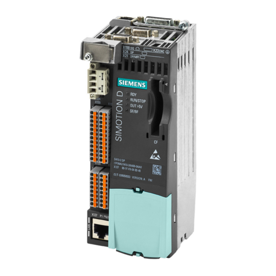
Description System overview SIMOTION D SIMOTION D is a drive-based version of SIMOTION based on the SINAMICS S120 drive family. With SIMOTION D, the SIMOTION PLC and motion control functionalities as well as the SINAMICS S120 drive software run on shared control hardware. SIMOTION D is available in two versions: ●... - Page 24 Description 2.1 System overview SIMOTION D410-2 Figure 2-1 SIMOTION D410-2 DP (pictured on left), SIMOTION D410-2 DP/PN (pictured on right) SIMOTION D410-2 is a compact Control Unit for single-axis applications. The Control Unit is snapped directly on to the SINAMICS Power Module in blocksize format and has an integrated drive control for either one servo, one vector or one V/f axis.
- Page 25 Description 2.1 System overview Example of a single-axis application Figure 2-2 Application example with one axis The example shows a single-axis application, consisting of a SIMOTION D410-2 (Control ① ② Unit) that is snapped directly on to the SINAMICS Power Module in blocksize format The motors are supplied with power via the Power Module.
- Page 26 Description 2.1 System overview The example shows an application with 3 axes, consisting of: ① ● One SIMOTION D410-2 DP (Control Unit) , snapped on to the Power Module in blocksize ③ format The SIMOTION D410-2 DP is snapped directly on to the SINAMICS Power Module. The motors are supplied with power via the Power Module.
- Page 27 Description 2.1 System overview Extension of the drive computing performance To fully utilize the motion control performance of a SIMOTION D410-2 when required, the drive- side computing performance can be extended by connecting additional SINAMICS S/G Control Units (e.g. CU305, CU310‑2, CU320‑2, CU250S‑2, etc.) via PROFIBUS or PROFINET to the SIMOTION D410‑2.
-
Page 28: System Components
Description 2.2 System components System components Overview SIMOTION D410-2 communicates with the components of the automation landscape via the following interfaces: ● PROFIBUS DP (D410-2 DP and D410-2 DP/PN) ● PROFINET IO (D410-2 DP/PN only) ● Ethernet ● DRIVE-CLiQ (DRIVE Component Link with IQ) ●... - Page 29 Description 2.2 System components PROFIBUS DP SIMOTION D410-2 can communicate with the following components via the PROFIBUS DP interface. Table 2-2 Components on PROFIBUS DP Component Function Programming device (PG/PC) … configures, assigns parameters, programs, and tests using the SIMOTION SCOUT En‐ gineering System (ES).
- Page 30 Description 2.2 System components PROFINET IO The SIMOTION D410‑2 DP/PN can communicate with the following components via the onboard PROFINET IO interface. Table 2-3 Components on the PROFINET IO Component Function Programming device (PG/PC) … configures, assigns parameters, programs, and tests using the SIMO‐ TION SCOUT Engineering System (ES).
- Page 31 Description 2.2 System components Ethernet The Control Unit can communicate with the following components via the Ethernet interfaces or be embedded in an automation environment: Table 2-4 Components on the Ethernet Component Function Programming device (PG/PC) … configures, assigns parameters, programs, and tests using the SIMOTION SCOUT En‐ gineering System (ES).
- Page 32 Description 2.2 System components Component Function Motors with … allow simplified commissioning and diagnostics, as the motor and encoder type are iden‐ DRIVE-CLiQ interface tified automatically. DMC20/DME20 … enables the number of DRIVE-CLiQ interfaces to be increased and the creation of a point- DRIVE-CLiQ hub to-point topology.
-
Page 33: I/O Integration
A detailed, regularly updated list of the I/O modules approved for use with SIMOTION, as well as notes on their use, can be found at Internet address (http:// support.automation.siemens.com/WW/view/en/11886029) In addition to the I/O modules enabled for SIMOTION, in principle all certified standard PROFIBUS slaves (DP-V0/DP-V1/DP-V2) and PROFINET IO devices with RT and IRT real- time classes may be connected to SIMOTION D410-2. -
Page 34: Commissioning Software
SIMOTION D410‑2. You will find detailed information on the SSPs in the readme files and in the software compatibility list at Internet address (http://support.automation.siemens.com/WW/view/en/ 18857317). Upgrading SIMOTION D410‑2 projects and hardware Projects that you have created for one SIMOTION D410‑2 firmware version can also be converted for other firmware versions. - Page 35 Description 2.4 Commissioning software Additional references SIMOTION SCOUT You will find detailed information on working with projects in the Configuration Manual. SIMOTION IT Diagnostics You will find detailed information on SIMOTION IT web server in the and Configuration Diagnostics Manual. SIMOTION D410-2 Commissioning and Hardware Installation Manual, 01/2015...
- Page 36 Description 2.4 Commissioning software SIMOTION D410-2 Commissioning and Hardware Installation Manual, 01/2015...
-
Page 37: Installing
Installing General requirements Mounting options SIMOTION D410‑2 comes in two designs: ● Mounting on the Power Module in blocksize format (mounted use). ● Mounting on a mounting plate (detached use). Open components SIMOTION D410‑2 is an open device! This means, you can only install the modules in housings, cabinets or electrical equipment rooms. -
Page 38: Mounting The Simotion D410-2 On The Power Module
Installing 3.2 Mounting the SIMOTION D410-2 on the power module Mounting the SIMOTION D410-2 on the power module Overview A SIMOTION D410-2 can be snapped directly on to a SINAMICS S120 Power Module in blocksize format via the PM-IF interface. Power Modules PM340 and PM240‑2 (PM240‑2 as of SIMOTION V4.4/SINAMICS V4.7) can be used. - Page 39 Installing 3.2 Mounting the SIMOTION D410-2 on the power module Mounting on the Power Module Snapping the SIMOTION D410-2 on to the Power PM340 Power Module with SIMOTION D410-2 Module (example PM340) (example PM340) SIMOTION D410-2 Commissioning and Hardware Installation Manual, 01/2015...
- Page 40 Installing 3.2 Mounting the SIMOTION D410-2 on the power module Disassembling the SIMOTION D410-2 To remove the SIMOTION D410-2 from the Power Module, the blue release, as shown in the figure, must be pressed down and SIMOTION D410-2 tilted forward. Figure 3-1 Removing the SIMOTION D410-2 from the Power Module SIMOTION D410-2...
-
Page 41: Mounting The Simotion D410-2 On The Mounting Plate
Installing 3.3 Mounting the SIMOTION D410-2 on the mounting plate Mounting the SIMOTION D410-2 on the mounting plate Overview Using a mounting plate, SIMOTION D410-2 can be operated separately, which means it is not mounted directly on the Power Module. Application examples: ●... - Page 42 Installing 3.3 Mounting the SIMOTION D410-2 on the mounting plate Mounting on mounting plate 1. The mounting plate is attached to the control cabinet. 2. The SIMOTION D410-2 is snapped on to the mounting plate. Figure 3-2 Mounting the SIMOTION D410-2 on the mounting plate Note When operating away from the Power Module, generally the power supply must be realized via the power supply connection (X124).
-
Page 43: Mounting The Simotion D410-2 In The Power Module Chassis
Installing 3.4 Mounting the SIMOTION D410-2 in the power module chassis Mounting the SIMOTION D410-2 in the power module chassis Figure 3-3 Mounting the CU310, for example, in the power module chassis, FX frame size The DRIVE-CLiQ cable and the cable for the 24 V supply must be correctly routed so that the front flap can close. - Page 44 Installing 3.4 Mounting the SIMOTION D410-2 in the power module chassis SIMOTION D410-2 Commissioning and Hardware Installation Manual, 01/2015...
-
Page 45: Connecting
Connecting General Overview Overview The SIMOTION D410‑2 has a number of interfaces that can be used for connecting the power supply and for communication with the other components of the system. ● The different SINAMICS components are interconnected via DRIVE‑CLiQ. ●... - Page 46 Connecting 4.1 General Overview Arrangement of the interfaces on the device Figure 4-1 SIMOTION D410-2 DP, arrangement of the interfaces on the device SIMOTION D410-2 Commissioning and Hardware Installation Manual, 01/2015...
- Page 47 Connecting 4.1 General Overview Figure 4-2 SIMOTION D410-2 DP/PN, arrangement of the interfaces on the device SIMOTION D410-2 Commissioning and Hardware Installation Manual, 01/2015...
- Page 48 Connecting 4.1 General Overview Overview of connections The following overview shows examples of the various interfaces and their connection possibilities. Figure 4-3 SIMOTION D410-2 connection possibilities SIMOTION D410-2 Commissioning and Hardware Installation Manual, 01/2015...
-
Page 49: General Rules For Operating The Simotion D410-2
Connecting 4.2 General rules for operating the SIMOTION D410-2 General rules for operating the SIMOTION D410-2 When integrating the SIMOTION D410-2 into a system, you must observe the following general rules. System startup after certain events Observe the following rules when starting up a system following certain events: ●... - Page 50 Connecting 4.2 General rules for operating the SIMOTION D410-2 Protection against external electrical interference Observe the following rules for protection against electric effects or faults: ● For all plants or systems, in which SIMOTION is installed, the plant or system must be connected to a protective conductor for the discharge of electromagnetic interference.
-
Page 51: Protective Conductor Connection And Potential Equalization
T20). This connection is also for the connection of an equipotential bonding conductor. Note Requirements for functional safety for machines and systems; reliability and EMC are only guaranteed with original SIEMENS cables. DANGER Danger to life from energized parts Death or serious injury will result if energized parts are touched. - Page 52 Connecting 4.3 Protective conductor connection and potential equalization Figure 4-4 Protective conductor connection, cabinet with mounting plate / equipotential bonding surface The protective conductor connections must be dimensioned as follows: Table 4-1 Conductor cross-section for copper protective connections Line supply cable in mm² Copper protective connections in mm²...
- Page 53 Connecting 4.3 Protective conductor connection and potential equalization Equipotential bonding A mounting plate serves simultaneously as an equipotential bonding surface. This means that no additional equipotential bonding is required within the drive line-up. If a common bright ⑨ mounting plate is not available, then equally good equipotential bonding must be established using cable cross-sections as listed in the table above or, as a minimum, with the same conductivity.
- Page 54 Connecting 4.3 Protective conductor connection and potential equalization NOTICE Fault of the data link or device defect with missing equipotential bonding Considerable leakage currents can flow via the data cable if equipotential bonding is not provided. Disturbance of the data link or device faults may result. Install an equipotential bonding conductor together with the data cable.
-
Page 55: Connecting The Power Supply
Connecting 4.4 Connecting the power supply Connecting the power supply 4.4.1 Safety rules Because of the wide range of possible applications, only the basic rules for electrical installation are described in this section. At a minimum, you must comply with these basic rules to ensure problem-free operation. - Page 56 Connecting 4.4 Connecting the power supply If digital outputs are used, a 24 V load power supply must be connected to the X124 screw- type terminal block. Note If a digital output is parameterized and the 24 V load power supply is not connected (or the level is too low), alarm A03506 is issued on the SINAMICS side (can also be parameterized as a fault).
- Page 57 Connecting 4.4 Connecting the power supply Fuse If the control is defective, an internal fuse protects the electronics from consequential damage (e.g. fire). In this case, the module must be replaced. SIMOTION D410-2 Commissioning and Hardware Installation Manual, 01/2015...
-
Page 58: Connecting Drive-Cliq Components
Connecting 4.5 Connecting DRIVE-CLiQ components Connecting DRIVE-CLiQ components Overview DRIVE-CLiQ connects the components in the SINAMICS S120 drive family as well as SIMOTION D410-2. DRIVE-CLiQ is a communications system, which enables SIMOTION D410-2 to automatically detect connected components. DRIVE-CLiQ provides a wiring tree, the topology of which can be visualized in SIMOTION SCOUT. -
Page 59: Connecting I/Os
Connecting 4.6 Connecting I/Os Connecting I/Os Connecting cables For the input/output wiring (X120, X121, X130, X131), use rigid or flexible cables with a conductor cross-section as stated in the manual. SIMOTION D410-2 Manual, Section "Digital inputs/outputs / temperature sensor / analog input."... -
Page 60: Creating A Shield Connection
Connecting 4.7 Creating a shield connection Creating a shield connection Using shielded cables The following options are available for the shield connection when using shielded cables: ● A shield connection using a shielding bus supplied separately ● Shield connection via the M3 screw-on shield connecting element on the housing of the SIMOTION D410-2 Using a shielding bus If a shielding bus is used, proceed as follows:... -
Page 61: Connecting Profibus/Mpi
Connecting 4.8 Connecting PROFIBUS/MPI Connecting PROFIBUS/MPI 4.8.1 PROFIBUS connection components Connection components Individual nodes are connected by means of bus connectors and PROFIBUS cable. Remember to provide a bus connector with a programming port at the ends of the subnet. This will give you the option of expanding the subnet if required (for example, for a PG or SIMATIC HMI device). -
Page 62: Length Of Profibus Cables
Connecting 4.8 Connecting PROFIBUS/MPI Connector features The bus connector is used to connect the PROFIBUS cable to the PROFIBUS DP interfaces. thus establishing a connection to additional nodes. Table 4-4 SIMOTION D410-2 PROFIBUS interfaces D410-2 DP D410-2 DP/PN PROFIBUS DP/MPI interface PROFIBUS DP interface –... -
Page 63: Rules For The Laying Of Profibus Cables
Connecting 4.8 Connecting PROFIBUS/MPI 4.8.4 Rules for the laying of PROFIBUS cables Laying of bus cable During laying of the PROFIBUS cable, you must: ● Not twist the cable ● Not stretch the cable ● Not squeeze the cable Supplementary conditions In addition, when laying a bus cable for indoor use, you must take into account the following supplementary conditions (dA = external cable diameter): Table 4-6... -
Page 64: Connection Rules In The Profibus Subnet
Connecting 4.8 Connecting PROFIBUS/MPI Connecting the bus connector Proceed as follows to connect the bus connector: 1. Plug the bus connector into the corresponding interface of the control unit. 2. Screw the bus connector into place. If the control unit is located at the start or end of a segment, you must switch on the terminating resistor ("ON"... - Page 65 Connecting 4.8 Connecting PROFIBUS/MPI Connection rules ● Before you interconnect individual nodes in a subnet, you must assign a unique PROFIBUS address to each node. ● Narrow down the number of nodes by limiting the PROFIBUS addresses to the highest address in the network.
-
Page 66: Operating Interface X21 As An Mpi
Connecting 4.8 Connecting PROFIBUS/MPI Example This illustration below shows an example configuration of a subnet with SIMOTION D410-2 DP. Figure 4-8 Networking example of SIMOTION D410-2 DP 4.8.7 Operating interface X21 as an MPI Applications The X21 interface can also be operated as an MPI interface instead of a PROFIBUS DP interface. - Page 67 Connecting 4.8 Connecting PROFIBUS/MPI When communicating with XSEND/XRECEIVE, there is no need to configure the connection in NetPro. XSEND/XRECEIVE can be used via PROFIBUS or MPI. ● Via PROFIBUS: For communication between SIMOTION devices ● Via MPI: For communication between SIMOTION and SIMATIC S7 devices The SIMOTION interface must be connected to the MPI interface of the SIMATIC S7 devices.
- Page 68 Connecting 4.8 Connecting PROFIBUS/MPI ● Every MPI station must be connected to the bus first and then activated. To disconnect the station, it must first be deactivated. Then, the station can be removed from the bus. ● Maximum cable lengths: –...
-
Page 69: Connecting Profinet Io Components (D410-2 Dp/Pn Only)
Connecting 4.9 Connecting PROFINET IO components (D410-2 DP/PN only) Connecting PROFINET IO components (D410-2 DP/PN only) 4.9.1 Wiring PROFINET Procedure As standard, a SIMOTION D410-2 DP/PN has a PROFINET IO interface with two ports. Suitable PROFINET cables and connectors must be used for the PROFINET connection. The autocrossing functionality of the PROFINET interface means crossed as well as uncrossed cables can be used. - Page 70 Connecting 4.9 Connecting PROFINET IO components (D410-2 DP/PN only) Figure 4-10 RJ45 PN connector with a 180° cable outlet Table 4-8 Connector types for PROFINET Connectors Designation Article number IE FC RJ45 plug 180 RJ45 FastConnect connector for Indus‐ trial Ethernet/PROFINET with 180° ca‐ ble outlet 6GK1901-1BB10-2AA0 6GK1901-1BB10-2AB0...
- Page 71 Connecting 4.9 Connecting PROFINET IO components (D410-2 DP/PN only) Additional references For further information about the cables, connectors, and stripping tool, see ● Section "Spare parts and accessories" in the SIMOTION D410-2 Manual IK PI, Industrial Communication ● Catalog SIMOTION D410-2 Commissioning and Hardware Installation Manual, 01/2015...
-
Page 72: Connecting Ethernet
Connecting 4.10 Connecting Ethernet 4.10 Connecting Ethernet Wiring Ethernet An Industrial Ethernet can be connected to the 8-pin RJ45 socket X127 P1. The interface supports a transmission rate of 10/100 Mbit/s. Suitable Ethernet cables and connectors must be used for the Ethernet connection. A shielded twisted pair cable is used for the networking. - Page 73 Connecting 4.10 Connecting Ethernet Additional references For further information about the cables and connectors, see the Industrial Communication IK PI Catalog. SIMOTION D410-2 Commissioning and Hardware Installation Manual, 01/2015...
-
Page 74: Routing
Connecting 4.11 Routing 4.11 Routing Routing describes the cross-network transfer of information from Network x to Network y. 4.11.1 Routing on SIMOTION D Routing between the different interfaces SIMOTION D410‑2 supports S7 routing between the following interfaces: ● Between Ethernet interface X127 and PROFIBUS interfaces X21 and X24 (X24 only available on D410‑2 DP) ●... - Page 75 Connecting 4.11 Routing Engineering System/HMI on PROFIBUS (example: D410‑2 DP) Figure 4-11 Example of PG/PC to PROFIBUS interface (X21) ● S7 routing to the other (master) PROFIBUS interfaces (only if configured) ● S7 routing to the PROFIBUS Integrated ● S7 routing to the Ethernet interface (X127 P1) SIMOTION D410-2 Commissioning and Hardware Installation Manual, 01/2015...
- Page 76 Connecting 4.11 Routing Engineering System/HMI on PROFINET (example: D410‑2 DP/PN) Figure 4-12 Example of PG/PC to PROFINET interface (PNxIO, X150) ● S7 routing to the (master) PROFIBUS interface (only if configured) ● S7 routing to the PROFIBUS Integrated ● S7 routing to Ethernet interface PN/IE (X127 P1) ●...
-
Page 77: Routing On Simotion D (Sinamics Integrated)
Connecting 4.11 Routing Engineering System/HMI on Ethernet (example: D410‑2 DP) Figure 4-13 Example of PG/PC to Ethernet interface (X127 P1) ● S7 routing to the other (master) PROFIBUS interfaces (only if configured) ● S7 routing to the PROFIBUS Integrated 4.11.2 Routing on SIMOTION D (SINAMICS integrated) S7 routing to the internal PROFIBUS on SINAMICS Integrated All SIMOTION D have an integrated SINAMICS drive control. -
Page 78: Connecting An External Encoder
Connecting 4.12 Connecting an external encoder 4.12 Connecting an external encoder Connecting the connecting cable Use only shielded cables to connect an external encoder to the encoder interface (X23). The shielding must be connected with the metallic or metallized connector housing. We recommend that bipolar encoders are used. -
Page 79: Commissioning (Hardware)
Commissioning (hardware) Overview Requirements The following requirements must be satisfied for the first commissioning of the SIMOTION D410‑2: ● Your system with SIMOTION D410‑2 has been installed and wired. ● Your PG/PC is connected to the SIMOTION D410‑2 via the PROFIBUS DP, Ethernet, or PROFINET (D410-2 DP/PN only) interface. -
Page 80: Inserting The Compactflash Card
Commissioning (hardware) 5.2 Inserting the CompactFlash card Inserting the CompactFlash card Characteristics of the CF card The CF card is mandatory for operation of the SIMOTION D410‑2. The SIMOTION Kernel (SIMOTION D firmware) and the software used to control the drives (SINAMICS firmware) are on the CF card. - Page 81 Commissioning (hardware) 5.2 Inserting the CompactFlash card Procedure To insert the CF card, perform the following steps: 1. The direction of insertion of the CF card is indicated by an arrow located on both the plug- in slot and the CF card. Align the CF card with the arrows. 2.
-
Page 82: Checking The System
Commissioning (hardware) 5.3 Checking the system Checking the system Procedure Check the final installed and wired system one more time before it is switched on, Observe the safety-relevant items of the following checklist. Checklist ✓ Have you observed all ESD measures when handling the components? Have all screws been tightened to their specified torque? Have all connectors been properly inserted and locked/screwed? Are all components grounded and have all shields been attached? -
Page 83: Switching On The Power Supply
Commissioning (hardware) 5.4 Switching on the power supply Switching on the power supply Switching on the external power supply Power is supplied to the SIMOTION D410‑2 via an external power supply unit, e.g. via a SITOP power supply. In exceptional cases, the SIMOTION D410-2 can also be supplied via the Power Module in blocksize format, see Section "Power supply"... - Page 84 Commissioning (hardware) 5.4 Switching on the power supply 3. All DRIVE-CLiQ connections (with SINAMICS Power Module, for example) are identified automatically. Note As long as the RDY LED continues to flicker, power-up is not complete and it is not possible to go online.
-
Page 85: Performing A Reset
Commissioning (hardware) 5.5 Performing a reset Performing a reset The RESET button is located behind the blanking cover on the SIMOTION D410‑2. The entire system is reset when the RESET button is pressed and a new power-up of the system forced. This operation is comparable with a "Power on Reset" but does not require the disconnection of the 24 V power supply. -
Page 86: User Memory Concept
Commissioning (hardware) 5.6 User memory concept User memory concept 5.6.1 SIMOTION D410-2 memory model The following figure provides an overview of the memory model of SIMOTION D410‑2. Figure 5-2 SIMOTION D410-2 memory model The SIMOTION Kernel (SIMOTION D firmware) contains the functions required for virtually all applications, and essentially acts as a PLC featuring an IEC 61131‑3-compliant command set as well as system functions for controlling various components, such as inputs and outputs. -
Page 87: Properties Of The User Memory
Commissioning (hardware) 5.6 User memory concept 5.6.2 Properties of the user memory Non‑volatile data Non‑volatile data makes it possible to retain relevant data for the user and the system even when the SIMOTION D410‑2 has been switched off. Information about the area which can be SIMOTION D410‑2 Manual, Section "Technical used for non-volatile data is available in the Data". - Page 88 Commissioning (hardware) 5.6 User memory concept The non-volatile data of the SIMOTION D410‑2 has the following properties: Table 5-2 Non-volatile data and real-time clock properties Characteristics Non‑volatile data Real-time clock (RTC) Location Non-volatile data are located in the The real-time clock is backed up NVRAM of the SIMOTION D410-2.
- Page 89 Commissioning (hardware) 5.6 User memory concept ● Data from SIMOTION IT ● Archived SCOUT project Volatile SIMOTION data (RAM / current data RAM) The volatile SIMOTION data are defined by the following properties: ● The volatile SIMOTION data are located in the RAM memory of the SIMOTION device. ●...
-
Page 90: Operations And Their Effect On The User Memory
Commissioning (hardware) 5.6 User memory concept 5.6.3 Operations and their effect on the user memory The operator actions and their effects on the user memory are described below. These operator actions are marked with arrows in the following displays: ● Figure 5-2 SIMOTION D410-2 memory model (Page 86) ●... - Page 91 Commissioning (hardware) 5.6 User memory concept To save the configuration data changed online to the offline project, you must first transfer the content of the current data RAM to the RAM using the menu command "Target system" > "Copy current data to RAM." Once you have done this, the configuration in SCOUT will no longer be consistent with the configuration in the target device, as a consistency check is performed on the RAM data.
- Page 92 Commissioning (hardware) 5.6 User memory concept backup file fails (e.g. because the capacity of the CF card is insufficient), this backup copy of the backup file is used the next time an attempt is made to restore the non-volatile SIMOTION data content.
- Page 93 Commissioning (hardware) 5.6 User memory concept Power failure If a power failure occurs, the real-time clock is buffered by means of an internal SuperCap. The non-volatile data are backed up on the D410‑2 permanently and maintenance-free in an NVRAM. In this way, the Control Unit is immediately ready for operation without data loss after a power failure.
- Page 94 Commissioning (hardware) 5.6 User memory concept Evaluating via the diagnostic buffer When they are issued, the following messages are entered once in the diagnostic buffer: Table 5-4 Messages of the diagnostic buffer Entry Meaning Remedy Non-volatile data loaded from a file Non-volatile SIMOTION data has been successfully restored from the backup (Persistent Data File Loading done)
- Page 95 Commissioning (hardware) 5.6 User memory concept A data loss of the real-time clock is signaled via the system variable device.persistentDataPowerMonitoring.rtcFailure = YES. The system variable device.persistentDataPowerMonitoring.persistentDataState shows the state of the non-volatile SIMOTION data after power-up. Table 5-6 State of the non-volatile SIMOTION data after powering up (persistentDataState system variable) State Meaning...
-
Page 96: Replacing Modules In The Spare Part Scenario
Commissioning (hardware) 5.6 User memory concept System variable States Description on the device .batteryexisting EXISTING EXISTING is only displayed when .batterynecessary is set to: ● MANDATORY or ● OPTIONAL or ● OPTIONAL_RTC and a battery is installed. NOT_EXISTING Battery is not available. State is statically set for D410-2. - Page 97 Commissioning (hardware) 5.6 User memory concept SIMOTION D410-2 power-up with the CF card (no module replacement) Prerequisite is that the same CF card and the same device are used. If the SIMOTION device powers up successfully, the serial number stored on the CF card is compared with the serial number of the device.
- Page 98 Commissioning (hardware) 5.6 User memory concept Restart after reloading The system variable device.startupData.operationMode is used to define whether the SIMOTION D410-2 Control Unit goes into the RUN state or the last operating state after a power-on/restart. Possible values of device.startupData.operationMode: ●...
-
Page 99: Fan
Commissioning (hardware) 5.7 Fan 5.7.1 Cooling the SIMOTION D410-2 Overview A fan is always required for operation of the SIMOTION D410-2. This is included in the scope of delivery of the D410-2 control unit. The fan operates temperature-controlled and is switched on depending on the air intake temperature and the CPU load. - Page 100 Commissioning (hardware) 5.7 Fan The states that can occur during operation are described in the following. Table 5-8 Overview of fan states State PeripheralFaultTask System variable _cpuDataRW.fanWarning The fan fails in the STOP operat‐ PeripheralFaultTask: =YES ing state, then RUN Is not called The fan fails in the RUN operat‐...
-
Page 101: Response To Overtemperature
Commissioning (hardware) 5.7 Fan Additional references SIMOTION Runtime You will find detailed information on setting up Taskstartinfo (#TSI) in the Basic Functions Function Manual. 5.7.3 Response to overtemperature Operation at overtemperature reduces the module service life and can result in damage to the module. - Page 102 Commissioning (hardware) 5.7 Fan Response to overtemperature Table 5-10 Response of the temperature monitoring Temperature... Response ... exceeds the 1st temperature Call of the PeripheralFaultTask: threshold (overtemperature) ● TSI#InterruptI = _SC_PC_INTERNAL_FAILURE (= 205) ● TSI#details = 16#00000002 Diagnostic buffer entry: "Temperature exceeded in the housing"...
-
Page 103: Parameter Assignment / Addressing
Parameter assignment / addressing Software requirements Engineering The following requirements must be satisfied for the commissioning of the SIMOTION D410‑2 Control Units: ● SIMOTION D410‑2 DP: at least SCOUT V4.3 SP1 HF1 and firmware V4.3 SP1 HF2 ● SIMOTION D410‑2 DP/PN: at least SCOUT V4.3 SP1 HF3 and firmware V4.3 SP1 HF3 Please note the information on the latest SIMOTION SCOUT DVD. -
Page 104: Creating A Project And Configuring The Communication
Parameter assignment / addressing 6.2 Creating a project and configuring the communication Creating a project and configuring the communication 6.2.1 Creating a SIMOTION project and inserting a SIMOTION D410-2 Procedure Proceed as follows to create a new project in SIMOTION SCOUT and insert a SIMOTION D410-2: 1. - Page 105 Parameter assignment / addressing 6.2 Creating a project and configuring the communication 3. In the project navigator, double-click "Insert SIMOTION device". The "Insert SIMOTION Device" dialog box is opened: Figure 6-1 Inserting a SIMOTION device 4. In the "Insert SIMOTION Device" dialog box, select the device, its version and the SIMOTION version.
-
Page 106: Configuring The Profibus Pg/Pc Interface
Parameter assignment / addressing 6.2 Creating a project and configuring the communication SINAMICS Integrated type For SIMOTION D410‑2, the type is always SINAMICS S120 Integrated. Version of the SINAMICS Integrated Depending on the selected SIMOTION version, several versions are available for the SINAMICS Integrated. - Page 107 Parameter assignment / addressing 6.2 Creating a project and configuring the communication Procedure Proceed as follows to configure the PROFIBUS DP interface: 1. In the "Interface Selection - D410" dialog box, select the entry "PROFIBUS DP/MPI (X21)" (in the case of the D410-2 DP, the following alternative is also available: PROFIBUS DP (X24)).
-
Page 108: Configuring The Ethernet Pg/Pc Interface
– "Diagnostics" > "Overview of service and diagnostics options" > "Part III" > "Go online" – "Insert device and connect to target system" > "Go online/offline" ● On the Internet at Internet address (http://support.automation.siemens.com/WW/view/en/ 22016709) ● In SIMOTION Utilities & Applications, FAQ "Online connections to SIMOTION devices". - Page 109 Parameter assignment / addressing 6.2 Creating a project and configuring the communication Procedure 1. In the "Interface Selection - D410" dialog box, select the entry "Ethernet PNxIE (X127)". Figure 6-3 Selecting the Ethernet interface 2. Select the interface parameter assignment that you would like to use to go online, and confirm with "OK".
-
Page 110: Display Of The Simotion D410-2 In Hw Config
– "Diagnostics" > "Overview of service and diagnostics options" > "Part III" > "Go online" – "Insert device and connect to target system" > "Go online/offline" ● On the Internet at Internet address (http://support.automation.siemens.com/WW/view/en/ 22016709) ● In SIMOTION Utilities & Applications, FAQ "Online connections to SIMOTION devices". - Page 111 Parameter assignment / addressing 6.2 Creating a project and configuring the communication Figure 6-4 Display of a SIMOTION D410-2 in HW Config Note According to the DNS conventions, "/" is a permissible character. For this reason, the Ethernet and PROFINET interfaces have a different name in the engineering software than on the module lettering ("/"...
-
Page 112: Configuring Profibus Dp
Parameter assignment / addressing 6.3 Configuring PROFIBUS DP Configuring PROFIBUS DP 6.3.1 General information about PROFIBUS DP communication Definition of PROFIBUS DP PROFIBUS DP is an international, open field bus standard specified in the European field bus Standard EN 50170 Part 2. PROFIBUS DP is optimized for high-speed, time-sensitive data transfer at field level. -
Page 113: Operating Simotion D410-2 On Profibus Dp
Parameter assignment / addressing 6.3 Configuring PROFIBUS DP 6.3.2 Operating SIMOTION D410-2 on PROFIBUS DP PROFIBUS DP interfaces (X21, X24) For connection to PROFIBUS DP, the SIMOTION D410‑2 DP has two interfaces (X21 and X24) and the SIMOTION D410‑2 DP/PN has one interface (X21). Table 6-1 SIMOTION D410-2 PROFIBUS interfaces D410-2 DP... - Page 114 Parameter assignment / addressing 6.3 Configuring PROFIBUS DP Remark Actions in the application DP/MPI DP master, not DP slave, iso‐ Application synchronized to DP slave (X24) DP slave synchroniza‐ isochronous chronous (can be monitored by the application) tion mechanisms Internal drive is synchronous with X24 DP slave, iso‐...
-
Page 115: Assigning Profibus Addresses In Hw Config
Parameter assignment / addressing 6.3 Configuring PROFIBUS DP 6.3.3 Assigning PROFIBUS addresses in HW Config Assigning PROFIBUS addresses Assign a PROFIBUS address to all devices before you start networking these in order to enable intercommunication. Note Before you assign any PROFIBUS addresses, please remember that all addresses must be unique on the PROFIBUS subnet. - Page 116 Parameter assignment / addressing 6.3 Configuring PROFIBUS DP To set the DP cycle of the SINAMICS Integrated, double-click the SINAMICS drive on the integrated PROFIBUS. The "DP Slave Properties" dialog box opens. You can synchronize the DP cycle of SINAMICS Integrated in the "Isochronous mode" tab. Table 6-3 SIMOTION D410-2 value range DP cycle...
-
Page 117: Rules For Cycle Clock Settings With Simotion D410-2 Dp
Parameter assignment / addressing 6.3 Configuring PROFIBUS DP Also observe the cycle clock setting rules in Section Rules for cycle clock settings with SIMOTION D410-2 DP (Page 117). 6.3.5 Rules for cycle clock settings with SIMOTION D410-2 DP The rules for making SIMOTION D410‑2 DP cycle clock settings are described below. For SIMOTION D410‑2 DP/PN, see Section Rules for cycle clock settings with SIMOTION D410-2 DP/PN (Page 131). - Page 118 Parameter assignment / addressing 6.3 Configuring PROFIBUS DP ● Onboard I/O p0799[0…2] (Control Unit) ● Terminal module I/O p4099 The corresponding cycle must be an integer multiple of the basic clock (DP cycle). If any change to the DP cycle violates this rule you must also change the SINAMICS cycle clocks.
-
Page 119: Cycle Clock Scaling Of External Profibus Interface To Internal Profibus Interface
Parameter assignment / addressing 6.3 Configuring PROFIBUS DP Current controller cycle clock With the SIMOTION D410-2, the following current controller cycle clocks p0115[0] can be configured for the SINAMICS Integrated: ● for servo: 125 μs (default) or 250 μs ● For vector and vector V/f: –... - Page 120 Parameter assignment / addressing 6.3 Configuring PROFIBUS DP ● The second external DP interface of a SIMOTION D410‑2 DP can be operated as an isochronous master (while the other is an isochronous slave) in order to operate external drives, for example. In this case, the cycle clock must be the same as the cycle clock of the internal PROFIBUS DP.
-
Page 121: Creating A New Profibus Dp Subnet
Parameter assignment / addressing 6.3 Configuring PROFIBUS DP 6.3.7 Creating a new PROFIBUS DP subnet SIMOTION SCOUT is used to network the SIMOTION D410‑2. Set up your user-specific bus parameters for the PROFIBUS DP interfaces when you configure the network. Note If a hardware configuration is loaded without a PROFIBUS network being configured on the CPU, a new PROFIBUS address that was previously set in HW Config or NetPro will not be... -
Page 122: Establishing A Pg/Pc Assignment
Parameter assignment / addressing 6.3 Configuring PROFIBUS DP The PROFIBUS subnet you created is displayed as a graphic object in HW Config. Note PROFIBUS DP functionality is both equidistant and isochronous in nature. As such, it can guarantee that bus cycles will have exactly the same length and ensures deterministic behavior. Applications: Connecting drives or synchronized I/O devices. -
Page 123: Configuring The Mpi Bus
Parameter assignment / addressing 6.4 Configuring the MPI bus Configuring the MPI bus 6.4.1 Operating interface X21 as an MPI The X21 interface can also be operated as an MPI interface. The typical (default) baud rate is 187.5 Kbaud. A baud rate of up to 12 MBaud can be set for communication with other CPUs. -
Page 124: Configuring Profinet Io
Parameter assignment / addressing 6.5 Configuring PROFINET IO Configuring PROFINET IO 6.5.1 General information about communication via PROFINET IO Communication cycle In PROFINET, the communication cycle is subdivided into different, time-specific intervals. The first interval is used for isochronous real‑time communication (IRT), followed by real‑time communication (RT) and standard TCP/IP communication. - Page 125 Parameter assignment / addressing 6.5 Configuring PROFINET IO For PROFIBUS DP, in isochronous operation all nodes are synchronized using a Global Control Signal created by the DP master. In PROFINET IO with IRT, a sync master generates a signal to which sync slaves synchronize themselves.
- Page 126 Parameter assignment / addressing 6.5 Configuring PROFINET IO Addressing In the delivery condition, the onboard PROFINET IO interface does not have an IP address or a subnet mask. Note The IP addresses 192.168.215.240 to 192.168.215.255 are reserved for internal communication in the SIMOTION D410‑2 (subnet mask 255.255.255.240). When configuring the PROFINET interface (X150), make sure that the internal addresses are not located within the network of this interface.
- Page 127 Parameter assignment / addressing 6.5 Configuring PROFINET IO These two ports are marked with an "R" in the module rack in HW Config. Note Only devices with MRP-capable ports may be inserted in an MRP ring. If MRP-capable ports are not used, the reconfiguration times can be in the seconds range. Bumpless media redundancy (MRPD) Requirement: SIMOTION V4.4.
-
Page 128: Setting A Send Cycle Clock And System Cycle Clocks
Parameter assignment / addressing 6.5 Configuring PROFINET IO 6.5.2 Setting a send cycle clock and system cycle clocks Requirement The SIMOTION system cycle clocks (servo/IPO/IPO_2) are based on the SINAMICS Integrated DP cycle or the PROFINET send cycle clock, depending on the PROFINET real-time class and the type of data transfer. - Page 129 Parameter assignment / addressing 6.5 Configuring PROFINET IO Setting the send cycle clock in HW Config The send cycle clock for PROFINET IO must be set in the "Domain Management" dialog in HW Config. To do this, select the "Edit" > "PROFINET IO" > "Domain management ..." menu command in HW Config and set the desired cycle clock.
-
Page 130: Properties Of Profinet
Parameter assignment / addressing 6.5 Configuring PROFINET IO Figure 6-7 System cycle clocks Additional information SIMOTION Communication System Manual. For further information, see the 6.5.3 Properties of PROFINET Properties The onboard PROFINET IO interface supports the parallel operation of: ● IRT - isochronous real-time Ethernet –... -
Page 131: Configuration Tasks
Parameter assignment / addressing 6.5 Configuring PROFINET IO Note For mixed operation of IRT and RT, make sure that the IRT-compatible devices form what is referred to as an IRT domain; i.e. there must not be any non-IRT devices on the data transmission link between the IRT devices. - Page 132 Parameter assignment / addressing 6.5 Configuring PROFINET IO The basis for the system clocks is generated internally if the PROFINET interface is not operated with RT class IRT or if IRT is set and no data are being transferred. This also applies if the PROFINET interface is operated as synchronization master with RT class IRT and data are being transferred.
- Page 133 Parameter assignment / addressing 6.5 Configuring PROFINET IO Example A default value of 4 ms is set for the SINAMICS setpoint channel p0115[3]. If the send cycle is to be set to 3 ms, the fact that an integer multiple value is required means that you will need to set 3 ms or 6 ms (for example) for the setpoint channel.
-
Page 134: Configuring An Ethernet Subnet
Parameter assignment / addressing 6.6 Configuring an Ethernet subnet Configuring an Ethernet subnet 6.6.1 General information about communication via Ethernet Properties of Ethernet SIMOTION D410‑2 has an onboard Ethernet interface X127 P1 PN/IE. You can connect an Industrial Ethernet with a transmission rate of 10/100 Mbit/s to the 8-pin RJ45 socket X127 P1. -
Page 135: Configuring The Ethernet Connection In Hw Config
Parameter assignment / addressing 6.6 Configuring an Ethernet subnet Default Ethernet addresses The following IP addresses are assigned by default for the Ethernet interface: Table 6-8 IP address assignment for SIMOTION D410‑2 Interface Use case Default address X127 P1 PN/ Insert SIMOTION device or IP address: 169.254.11.22... -
Page 136: Configuring Ethernet Addresses In Hw Config
Parameter assignment / addressing 6.6 Configuring an Ethernet subnet 4. Close the "Properties - PNxIE" dialog box with "OK". 5. Save and compile the modified hardware configuration. 6. Load the new hardware configuration to the SIMOTION D410‑2 via PROFIBUS DP/ Ethernet/PROFINET IO. -
Page 137: Reading Out Ip And Mac Address
PST Tool or PRONETA. You will find more information on PRONETA and PST Tool on the Internet. ● PRONETA: See Internet address (http://support.automation.siemens.com/WW/view/en/ 67460624) ● PST Tool: See Internet address (http://support.automation.siemens.com/WW/view/en/... - Page 138 Parameter assignment / addressing 6.6 Configuring an Ethernet subnet X127 (IE) ● Active MAC Address: 08-00-06-73-25-3E ● IP address: 169.254.11.22 ● Subnet mask: 255.255.0.0 ● Standard gateway: 0.0.0.0. As an alternative, you can determine the IP address as follows: ● By selecting "Project" > "Accessible nodes" in SIMOTION SCOUT ●...
-
Page 139: Commissioning (Software)
Commissioning (software) Overview of commissioning 7.1.1 Requirements for commissioning The requirements for commissioning the SIMOTION D410-2 are as follows: ● The system has been connected and wired. ● The SIMOTION D410-2 is switched on and powered up (STOP operating state). ●... - Page 140 Commissioning (software) 7.1 Overview of commissioning Apart from the symbolic assignment, no further configuration is required for the communication. As addresses no longer have to be configured, the connection is retained even with address offsets. Note During the configuration of drive objects (DO drive, DO encoder, ...) as well as in the Telegram Configuration dialog box (see Section Telegram configuration (Page 195)), you can deactivate the automatic telegram configuration and the automatic telegram adaptation.
- Page 141 Commissioning (software) 7.1 Overview of commissioning Conversion from upgraded projects to symbolic assignment is possible, but this requires post- editing of the project, especially for free telegram configurations (e.g. for TM15 DI/DO, TM31). Note If the symbolic assignment is activated later, previously existing telegram settings and BICO interconnections for all SINAMICS telegrams that are set to Standard/Automatic (Communication ->...
- Page 142 You will find the documentation of older SIMOTION versions on the Internet at the following address (http://support.automation.siemens.com/WW/view/en/40211807). For further information on the configuration of the TO axis and TO externalEncoder, see the TO Axis Electrical/Hydraulic, External Encoder Function Manual.
-
Page 143: Procedure When Commissioning
Commissioning (software) 7.1 Overview of commissioning 7.1.3 Procedure when commissioning Commissioning steps This section shows you how to configure a system and test the configured drives and axes. The steps in commissioning are listed below in the order as recommended: 1. - Page 144 Commissioning (software) 7.1 Overview of commissioning Download CPU / drive unit to target device The configuration is only loaded to the device selected in the project tree which means that the function needs to be performed separately for each D410-2 and SINAMICS Integrated.
-
Page 145: Performing An Offline Configuration
Commissioning (software) 7.2 Performing an offline configuration Performing an offline configuration 7.2.1 Overview Introduction In the case of offline configuration, the project is created while not all of the hardware components (in particular drives) are available. In this way, a SIMOTION project in the office environment can be created up to a point where a basic project specification including a program exists. -
Page 146: Accessing The Drive Wizard
Commissioning (software) 7.2 Performing an offline configuration 7.2.2 Accessing the drive wizard Integrated drive SIMOTION D410-2 features an integrated SINAMICS S120 drive (control unit) which is automatically included when you insert the SIMOTION D410-2 in the project navigator. The integrated drive must be operated in isochronous mode using PROFIdrive-compliant telegram types. - Page 147 Commissioning (software) 7.2 Performing an offline configuration 1. Enter a drive name in the "Drive Properties" dialog box and select the drive type (servo or vector). Figure 7-1 Drive properties 2. In the "Control Structure" dialog, you can select the function modules and the control type. SIMOTION D410-2 Commissioning and Hardware Installation Manual, 01/2015...
- Page 148 Commissioning (software) 7.2 Performing an offline configuration Figure 7-2 Control structure SIMOTION D410-2 Commissioning and Hardware Installation Manual, 01/2015...
- Page 149 Commissioning (software) 7.2 Performing an offline configuration 3. In the "Power Unit" dialog, use the article number to select your power unit from the list. Figure 7-3 Selecting a power unit SIMOTION D410-2 Commissioning and Hardware Installation Manual, 01/2015...
- Page 150 Commissioning (software) 7.2 Performing an offline configuration 4. Select in the "Power Unit Supplementary Data" dialog the component added to the power unit. The selection of the component depends on the construction type. – SIMOTION D410‑2 DP or D410‑2 DP/PN: The SIMOTION D410‑2 is snapped directly onto the blocksize format Power Module.
- Page 151 Commissioning (software) 7.2 Performing an offline configuration 5. In the next dialog, select the motor and, where applicable, the motor type: – Either by selecting a standard motor from the list – Or by entering the motor data – Or by automatically identifying the motor (motor with DRIVE-CLiQ interface) Figure 7-5 Selecting a motor Note...
- Page 152 Commissioning (software) 7.2 Performing an offline configuration 6. Select a motor holding brake (if installed). Figure 7-6 Selecting a motor holding brake SIMOTION D410-2 Commissioning and Hardware Installation Manual, 01/2015...
- Page 153 Commissioning (software) 7.2 Performing an offline configuration 7. If you are using a motor that is not equipped with a DRIVE‑CLiQ interface, select the encoder order number in the "Encoder Selection via Motor Order Number" dialog box. Figure 7-7 Selecting a motor encoder (1) Figure 7-8 Selecting a motor encoder (2) SIMOTION D410-2...
- Page 154 Commissioning (software) 7.2 Performing an offline configuration Note If required, you can configure a second or third encoder in the "Encoder" dialog box. You can transmit a maximum of two encoder values to SIMOTION via the axis telegram. In the case of motors with a DRIVE-CLiQ interface, the motor encoder is identified automatically.
- Page 155 Commissioning (software) 7.2 Performing an offline configuration 8. The communication for the control of the SINAMICS drive is configured in the following dialog box. It is recommended that these settings be made automatically by the engineering system. Figure 7-9 Configuring the process data exchange (standard) You can also make the settings manually for the process data exchange by selecting "User- defined".
- Page 156 Commissioning (software) 7.2 Performing an offline configuration Figure 7-10 Configuring the process data exchange (user-defined) Information about the manual setting options can be found in the online help and in the manuals for the SINAMICS S120 drive system. 9. After you have configured all of the settings in the drive wizard, the "Summary" dialog box displays a list of all settings.
- Page 157 Commissioning (software) 7.2 Performing an offline configuration Figure 7-11 Finishing the drive The configured drive is displayed in the project navigator. An overview of your configured SINAMICS components is available in the "SINAMICS_Integrated" > "Topology" dialog. Additional references If you configure the drive telegrams manually, you can find detailed information on the respective telegram types in the following: Motion Control, TO Axis Electric/Hydraulic, External Encoder Function Manual ●...
-
Page 158: Downloading The Project To The Target System
Commissioning (software) 7.2 Performing an offline configuration 7.2.4 Downloading the project to the target system Procedure 1. Save and compile the project. 2. Go online with the SIMOTION D410-2. 3. To load the project, perform "Download project to target system". The data must also be saved on the CompactFlash card to ensure that the project is retained in the event of a power failure. -
Page 159: Loading A Project Created Offline To The Compactflash Card
Commissioning (software) 7.2 Performing an offline configuration 7.2.5 Loading a project created offline to the CompactFlash card Procedure You can use a card reader to write the entire project to the CF card, even in offline mode. In SIMOTION SCOUT, you can call the "Load to file system" function in the context menu of the SIMOTION device. -
Page 160: Downloading The Project Incl. Sources And Additional Data
Commissioning (software) 7.2 Performing an offline configuration 7.2.6 Downloading the project incl. sources and additional data Overview It is possible to download additional data (e.g. sources) to the target device when saving a project to the CF card or downloading to the SIMOTION D410‑2. These data are required for: ●... - Page 161 Commissioning (software) 7.2 Performing an offline configuration 3. Open the project. 4. Go online with the SIMOTION D410-2. 5. In the project navigator, select the SIMOTION D410-2 and select the "Target system" > "Load" > "Save archived project to card..." menu command. 6.
-
Page 162: Performing An Online Configuration
Commissioning (software) 7.3 Performing an online configuration Performing an online configuration 7.3.1 Overview Introduction You can configure the plant in online mode after having completed its wiring. You can use the "Automatic configuration" function to load the SINAMICS components connected via DRIVE- CLiQ to your PG/PC. -
Page 163: Establishing The Online Connection
● In the FAQ for SIMOTION Utilities & Applications SIMOTION Utilities & Applications is provided as part of the SIMOTION SCOUT scope of delivery. ● FAQOnline connection to SIMOTION (http://support.automation.siemens.com/WW/view/ en/22016709) 7.3.3 Starting automatic configuration Requirement You have established the online connection to SINAMICS Integrated. - Page 164 Commissioning (software) 7.3 Performing an online configuration Procedure 1. In the project navigator, open the "Automatic Configuration" dialog with the "SINAMICS_Integrated" > "Automatic configuration" menu command. Figure 7-12 Starting automatic configuration 2. Click the "Configure" button. 3. If the drive unit is not in the "First commissioning" state, the factory settings are restored after acknowledging a prompt.
- Page 165 Commissioning (software) 7.3 Performing an online configuration 6. Click "Create" to start the automatic configuration. The configuration data is uploaded (Load to PG) automatically as soon as automatic configuration is completed. Note The components' firmware is automatically updated, depending on the firmware version on the SINAMICS components and on the CF card.
-
Page 166: Reconfiguring Sinamics Components
Commissioning (software) 7.3 Performing an online configuration Result The DRIVE-CLiQ components loaded to the user project by means of automatic configuration are displayed in the project navigator. Figure 7-14 Project navigator with the downloaded DRIVE-CLiQ components You must then ● If required, reconfigure SINAMICS components (e.g. components without a DRIVE‑CLiQ interface, such as an encoder connected to the onboard encoder interface). -
Page 167: Downloading The Project To Simotion D410-2
Commissioning (software) 7.3 Performing an online configuration This procedure corresponds to the description in Section Performing an offline configuration (Page 145). The amount of editing work involved depends on the components used. For example, in the case of a motor with a DRIVE-CLiQ interface, the motor and encoder type are identified automatically. - Page 168 Commissioning (software) 7.3 Performing an online configuration Note If you have deselected the "Drives" option under "Tools" > "Settings" > "Download" in SIMOTION SCOUT, you must download the configuration separately to each drive (SINAMICS Integrated). To do this, select the drive (e.g. SINAMICS Integrated) in the project navigator and perform "Download CPU / drive unit to target device".
-
Page 169: Additional Information On Configuring The Sinamics Integrated
Commissioning (software) 7.4 Additional information on configuring the SINAMICS Integrated Additional information on configuring the SINAMICS Integrated 7.4.1 Setting DP Slave properties Settings in HW Config Depending on the cycle clock ratios (bus cycle, servo cycle) and the drive used, it may be necessary to adapt the properties of the DP slave (SINAMICS Integrated) on the PROFIBUS Integrated. - Page 170 Commissioning (software) 7.4 Additional information on configuring the SINAMICS Integrated ● Changing the DP cycle (T Depending on the requirements in terms of the quantity structures and response times, the SIMOTION Runtime Basic Functions Function DP cycle may need to be changed. (See also Manual).
-
Page 171: Using Vector Drives
Commissioning (software) 7.4 Additional information on configuring the SINAMICS Integrated Additional references Additional information can be found SINAMICS S120 Function Manual ● In the SIMOTION Runtime Basic Functions Function Manual ● 7.4.2 Using vector drives Changes need to be made in HW Config when SINAMICS vector drives are used. This means, for example, that the T time and the minimum DP cycle for drives in chassis format depend on the type of device used. - Page 172 Commissioning (software) 7.4 Additional information on configuring the SINAMICS Integrated Table 7-1 Vector drive Example Settings Vector drive (chassis format) = at least 375 µs Current controller cycle = 375 µs = 1.5 ms (... or 3 ms, or 6 ms ..) Speed controller cycle = 1.5 ms MAPC For the SIMOTION D410-2, a minimum of 1 ms is recom‐...
-
Page 173: Setting The Simotion Time Of Day
Commissioning (software) 7.4 Additional information on configuring the SINAMICS Integrated ● The PROFIBUS Integrated of a SIMOTION D410‑2 is always isochronous! This means that a current controller sampling time of 400 µs is not possible. ● With CU parameter p0092 = 1, the sampling times are preassigned in a way that enables isochronous operation with a control system. - Page 174 Commissioning (software) 7.4 Additional information on configuring the SINAMICS Integrated System runtime The entire system runtime is displayed in CU parameter p2114. ● r2114[0] indicates the system runtime in milliseconds. After reaching 86,400,000 ms (24 hours), the value is reset. ●...
- Page 175 Commissioning (software) 7.4 Additional information on configuring the SINAMICS Integrated Procedure Proceed as follows to convert the SINAMICS clock to UTC format and to synchronize this with the SIMOTION clock: 1. In the project navigator, call the shortcut menu of the SIMOTION D410‑2. 2.
- Page 176 Commissioning (software) 7.4 Additional information on configuring the SINAMICS Integrated Compensation of runtime deviations To compensate for deviations between the SIMOTION and SINAMICS clocks, the time of day is automatically synchronized at regular intervals. The following behavior must be taken into consideration when setting the SIMOTION time: ●...
-
Page 177: Backing Up / Restoring / Deleting Sinamics Nvram Data
Commissioning (software) 7.4 Additional information on configuring the SINAMICS Integrated is displayed in the parameter, whereby [0] and [2] are milliseconds and [1] and [3] are days. Note The diagnostic buffer entries are not converted to the new time when the time is changed. 7.4.5 Backing up / restoring / deleting SINAMICS NVRAM data Requirement... - Page 178 Commissioning (software) 7.4 Additional information on configuring the SINAMICS Integrated Restoring the NVRAM data The SINAMICS NVRAM data can only be restored when none of the connected drives has a pulse enable. When restoring, the PMEMORY.ACX file is accessed first. If this is available and is error-free, it is loaded.
- Page 179 Commissioning (software) 7.4 Additional information on configuring the SINAMICS Integrated The following are not deleted: ● CU operating hours counter ● CU temperature and ● Safety logbook At the end of the deletion, the initialization data of the applications is in the NVRAM, similar to after a device automatic commissioning (with the exception of the above-mentioned data).
-
Page 180: Sinamics Diagnostic Buffer
Commissioning (software) 7.4 Additional information on configuring the SINAMICS Integrated Error Cause Backup could not be completed (e.g. memory card removed during the backup) Restoration not possible: Memory card is not inserted Restoration not possible: Checksum of the NVRAM data backup file is faulty Restoration not possible: No backup available Note The memory card must always remain inserted for the SIMOTION D410-2. -
Page 181: Acyclic Communication With The Drive
Commissioning (software) 7.4 Additional information on configuring the SINAMICS Integrated You also have the option of viewing the SIMOTION D410‑2 and SINAMICS Integrated diagnostic buffers via SIMOTION IT web server. 7.4.7 Acyclic communication with the drive Overview PROFIdrive drive units are supplied with control signals and setpoints by the controller and return status signals and actual values. -
Page 182: Control Properties And Performance Features
Commissioning (software) 7.4 Additional information on configuring the SINAMICS Integrated The functions available in the DP V1 library include: ● Buffer management (coordination of a number of parallel DP V1 services) ● StartUp (function for coordinating startup of the SINAMICS drive with SIMOTION) ●... - Page 183 Commissioning (software) 7.4 Additional information on configuring the SINAMICS Integrated cam outputs and the measuring input inputs (only for global measuring inputs) to function correctly, the sampling times must be known to the engineering system. Sampling times <> 125 µs occur in the following cases: ●...
-
Page 184: Testing The Configured Drive Using The Drive Control Panel
Commissioning (software) 7.5 Testing the configured drive using the drive control panel Testing the configured drive using the drive control panel You can test a configured drive using the drive control panel where you can define a speed value by setting a scaling factor. The drive control panel should only be used for commissioning. - Page 185 Commissioning (software) 7.5 Testing the configured drive using the drive control panel 3. Click "Assume control priority". The "Assume Control Priority" dialog box is opened. Figure 7-18 Assuming control priority 4. Read the notes and confirm these with "Accept." 5. Activate the "Enables" checkbox to enable the drive. All enables are now set with the exception of ON/OFF1.
-
Page 186: Creating And Testing Axes
Commissioning (software) 7.6 Creating and testing axes Creating and testing axes 7.6.1 Overview of SIMOTION Engineering Performing engineering with SIMOTION SCOUT The SIMOTION SCOUT engineering system can be used to insert axes in your project. 1. First, run through the axis wizard to configure the axes and interconnect to the real drive (e.g. - Page 187 Commissioning (software) 7.6 Creating and testing axes Inserting an axis 1. In the Project Navigator, double-click the entry "Axis" > "Insert Axis." This will access the axis wizard. Set the required technology and then click "OK." Figure 7-20 Inserting an axis 2.
- Page 188 Commissioning (software) 7.6 Creating and testing axes Figure 7-21 Defining the axis type 3. Create a new drive or make the assignment to an existing drive. SIMOTION D410-2 Commissioning and Hardware Installation Manual, 01/2015...
- Page 189 Commissioning (software) 7.6 Creating and testing axes Figure 7-22 Assigning a drive The following setting options are available for the drive assignment: ● Assigning a drive Assigning a previously configured drive. ● Define a subsequent assignment The axis should not be assigned to a drive until a later point in time. Accordingly: –...
- Page 190 Commissioning (software) 7.6 Creating and testing axes ● Creating a drive From the Assignment dialog box, a new drive can be created on an existing drive unit (e.g. SINAMICS Integrated) and assigned to the axis. This allows the axis, including the drive, to be created in one operation.
- Page 191 Commissioning (software) 7.6 Creating and testing axes Figure 7-23 Axis wizard summary Note During system power-up, reference variables as well as drive and encoder data of the SINAMICS are automatically taken over for the SIMOTION configuration data of the SIMOTION technology objects "TO axis" and "TO externalEncoder". Encoder assignment With a position axis, encoder 1 is also created on the TO axis (motor encoder) and automatically assigned to the first encoder on the drive.
- Page 192 Commissioning (software) 7.6 Creating and testing axes Save and compile the project and download it to the target system. After running through the axis wizard, the symbolic drive assignment is displayed via "Configuration" of the axis as well as via the address list (All addresses view). The Assignment dialog box can be called again from these dialog boxes using the button.
-
Page 193: Testing An Axis With The Axis Control Panel
Commissioning (software) 7.6 Creating and testing axes 7.6.3 Testing an axis with the axis control panel Axis control panel The axis control panel is used exclusively for testing axes. You can use the axis control panel for the following tasks, for example: ●... - Page 194 Commissioning (software) 7.6 Creating and testing axes 3. Click "Assume control priority". Note In order to move the axis from the PG/PC, you must assume control priority. However, by pressing the SPACER bar, you can stop the axis at any time. 4.
-
Page 195: Setting Up Addresses And Message Frames
Commissioning (software) 7.7 Setting up addresses and message frames Setting up addresses and message frames Overview After all SINAMICS components have been configured, addresses must be determined for the process data exchange between the drive and the controller. This procedure depends on whether symbolic assignments are used. ●... - Page 196 Commissioning (software) 7.7 Setting up addresses and message frames Procedure In the project navigator, open the "Communication" > "Telegram configuration" entry under "SINAMICS_Integrated." The "SINAMICS Integrated - Telegram Configuration" dialog box is displayed with the PROFIdrive PZD telegrams tab. The dialog box lists all the available drive objects. The possible setting options are described in the following.
- Page 197 Commissioning (software) 7.7 Setting up addresses and message frames Table 7-5 Explanation of the figure Meaning ① Selection of a telegram ● The drive telegrams (telegrams 1 ... 6 and telegram 1xx) are defined in accordance with the PROFIdrive specification and can be selected based on the required functional scope. ●...
- Page 198 Commissioning (software) 7.7 Setting up addresses and message frames Note If symbolic assignment is deactivated, the following applies: If the telegrams for drive objects (drives, Terminal Modules, etc.) change, you must set up the addresses again. The addresses are not updated automatically. Telegram status The icons in the status column show the following information: The telegram differs from the configuration in HW Config.
-
Page 199: Linking An Additional Encoder (Optional)
Commissioning (software) 7.8 Linking an additional encoder (optional) Linking an additional encoder (optional) 7.8.1 General information SIMOTION D410-2 features a DRIVE-CLiQ X100 interface for connecting an encoder. SIMOTION D410-2 provides the option of integrating and configuring further encoders in addition to the motor encoder. The following encoders are supported for operation with SIMOTION D410-2: ●... -
Page 200: Configuring Additional Encoders On The Drive
Commissioning (software) 7.8 Linking an additional encoder (optional) 7.8.2 Configuring additional encoders on the drive The following options are available for configuring additional encoders on the drive: ● Configuration of a second encoder on the drive ● Configuration of an encoder as drive object (as of SINAMICS firmware V4.3) Configuring a second encoder on the drive The configuration of a second encoder on the drive is useful when the second encoder value is also to be used for this drive (e.g. -
Page 201: Connecting Additional Encoders Via Profibus/Profinet
Commissioning (software) 7.8 Linking an additional encoder (optional) Note In the same way as for axes, a "DO encoder" can also be symbolically interconnected to a "TO externalEncoder". 7.8.3 Connecting additional encoders via PROFIBUS/PROFINET Options With regard to encoder integration, further encoders can also be connected via PROFIBUS or PROFINET. -
Page 202: Symbolic Assignment Of I/O Variables
Commissioning (software) 7.9 Symbolic assignment of I/O variables Symbolic assignment of I/O variables 7.9.1 Assignment to the PROFIdrive message frame of the TO axis I/O variables which you require for purposes such as display and diagnostics can be assigned from the address list to individual components (status word, for example) via the assignment dialog of the PROFIdrive message frame. - Page 203 Commissioning (software) 7.9 Symbolic assignment of I/O variables Procedure 1. Open the Assignment dialog box from the address list (view of all addresses). The Assignment dialog opens with the corresponding assignment partners. 2. Click the "..." button in the parameter selection line to open the parameter list. Figure 7-29 Assignment dialog for drive parameters SIMOTION D410-2...
- Page 204 Commissioning (software) 7.9 Symbolic assignment of I/O variables 3. Select the desired signal source (e.g. DO drive). Then select the required parameter. Figure 7-30 Dialog box for the DO and parameter selection 4. Click "OK" to accept the selection. SIMOTION D410-2 Commissioning and Hardware Installation Manual, 01/2015...
- Page 205 Commissioning (software) 7.9 Symbolic assignment of I/O variables 5. The desired SINAMICS parameter is assigned to the I/O variable in the interconnection dialog box. Figure 7-31 Assigned drive parameters 6. Click "OK" to accept the assignment. The following table shows the possible types of assignment: Name of the assignment Data type Direction...
-
Page 206: Configuring Drive-Related I/Os
Commissioning (software) 7.10 Configuring drive-related I/Os 7.10 Configuring drive-related I/Os 7.10.1 Overview of the symbolic configuration of I/Os Overview SIMOTION D410-2 as well as the SINAMICS S110/S120 control units and additional components (TMs) have I/Os that can be used by the drive unit and by SIMOTION. I/Os originally assigned to SINAMICS can be used by SIMOTION only when they have been interconnected to a message frame. -
Page 207: Configuration Options
Commissioning (software) 7.10 Configuring drive-related I/Os Procedure The configuration of the I/Os is divided into two basic steps: 1. Configuring I/O terminals (Page 207) The functionality of an I/O channel is configured (e.g. configuration of a DI/DO as digital output). 2. -
Page 208: Simotion D410-2 Configuring I/Os
Commissioning (software) 7.10 Configuring drive-related I/Os Note The module hardware for TM15 and TM15 DI/DO is identical. A distinction is only made by the addition of the component in the SIMOTION SCOUT Project Navigator using "Inserting input/ output component." I/Os that are originally assigned to the SINAMICS drive unit can also be used by SIMOTION via configuration. - Page 209 Commissioning (software) 7.10 Configuring drive-related I/Os ● Used as a global measuring input input for SIMOTION with "Measuring input (SIMOTION)" ● Used as an output cam output for SIMOTION with "output cam (SIMOTION)" Figure 7-32 Configuration of D410-2 I/Os (terminal X121) 24 V supply for DO If no digital outputs are used, the SIMOTION D410-2 can be supplied via the Power Module.
-
Page 210: Configuration Of Cu3Xx/Tmxx I/Os
Commissioning (software) 7.10 Configuring drive-related I/Os 7.10.4 Configuration of CU3xx/TMxx I/Os Overview The configuration is performed in a similar way as for the onboard I/Os for the SIMOTION D410-2, i.e. the I/Os can be ● BICO-interconnected (use as drive I/O) ●... -
Page 211: Configuring Technology Objects And I/O Variables
Commissioning (software) 7.11 Configuring technology objects and I/O variables 7.11 Configuring technology objects and I/O variables 7.11.1 Configuring global measuring inputs Overview The type of measuring input must be selected during the configuration of the TO measuring input, see following table. Table 7-8 Measuring input types Measuring input types... -
Page 212: Configuring Local Measuring Inputs
Commissioning (software) 7.11 Configuring technology objects and I/O variables Figure 7-33 Configuration of a global measuring input for SIMOTION D410-2 Additional references Detailed information on the configuration of the TO measuring input can be found in the SIMOTION Output Cams and Measuring Inputs Function Manual. 7.11.2 Configuring local measuring inputs Local measuring inputs are drive-related measuring inputs. - Page 213 Commissioning (software) 7.11 Configuring technology objects and I/O variables The following output types are available: Table 7-9 TO outputCam / TO camTrack output types Cam output on... Explanation Output cam output (CAM) The cam output is performed on the basis of an internal time stamp. The temporal resolution of the cam output depends on the hardware used.
- Page 214 Commissioning (software) 7.11 Configuring technology objects and I/O variables Then assign a hardware output. For this purpose, click ("assign") to open the Assignment dialog box and select a free (i.e. not yet used) I/O. Note Only those I/Os that have the appropriate functionality (DO_xx [channel name, terminal number]) are displayed.
-
Page 215: Configuring An I/O Variable
Commissioning (software) 7.11 Configuring technology objects and I/O variables 7.11.4 Configuring an I/O variable Overview You have two ways to assign an I/O variable to I/O terminals: ● Assignment via preferred interconnection (e.g. DI_8 [DI/DO 8, X121.7]) To do this, you must use the SIMOTION preferred interconnection for the corresponding input/outputs of the SINAMICS DOs. - Page 216 Commissioning (software) 7.11 Configuring technology objects and I/O variables Alternatively, you can assign SIMOTION to an I/O channel during the terminal configuration (e.g. by selecting "DI (SIMOTION)", see Section SIMOTION D410-2 Configuring I/Os (Page 208)). TO axis The symbolic assignment of I/Os is also supported by the TO axis (e.g. for a HW limit switch).
-
Page 217: Creating A Dmc20/Dme20 Drive-Cliq Hub
Commissioning (software) 7.12 Creating a DMC20/DME20 DRIVE-CLiQ hub 7.12 Creating a DMC20/DME20 DRIVE-CLiQ hub 7.12.1 Hub properties DRIVE‑CLiQ hub characteristics The DMC20 and DME20 DRIVE‑CLiQ hub modules are used to implement point-to-point distribution of a DRIVE‑CLiQ line. With the DMC20/DME20, an axis grouping can be expanded with 4 DRIVE‑CLiQ sockets for additional subgroups. -
Page 218: Creating A Drive-Cliq Hub
Commissioning (software) 7.12 Creating a DMC20/DME20 DRIVE-CLiQ hub 7.12.2 Creating a DRIVE-CLiQ hub Introduction You can directly insert a DMC20/DME20 in the project navigator. The hub is not wired when you insert the DMC20/DME20 and is displayed in the topology tree in the component storage. The hub has to be wired manually. -
Page 219: Creating And Programming Tm41
Commissioning (software) 7.13 Creating and programming TM41 7.13 Creating and programming TM41 7.13.1 TM41 properties The TM41 terminal module can be used to expand the number of digital I/Os and analog inputs within a drive system. TM41 also returns TTL signals which emulate an incremental encoder, for example, for a master control system. -
Page 220: Configuring The Tm41 Using The Axis Wizard
Commissioning (software) 7.13 Creating and programming TM41 7.13.3 Configuring the TM41 using the axis wizard Requirement After configuring the TM41 for a SINAMICS Integrated device in the project navigator, you can interconnect it with an axis using the Axis Wizard. The Wizard implements the TM41 as drive device. - Page 221 Detailed information on configuring incremental encoder emulation with the TM41 can be found ● FAQs at the following Internet address (http://support.automation.siemens.com/WW/view/en/27554028) ● SIMOTION Utilities & Applications SIMOTION Utilities & Applications is part of the scope of delivery of SIMOTION SCOUT.
-
Page 222: Optimizing The Drive And Controller
Commissioning (software) 7.14 Optimizing the drive and controller 7.14 Optimizing the drive and controller 7.14.1 Overview of automatic controller setting Overview The SIMOTION SCOUT engineering system offers a wizard for the automatic controller setting for the controller optimization of the drive. In the "Automatic Controller Setting"... -
Page 223: Automatic Speed Controller Setting
Commissioning (software) 7.14 Optimizing the drive and controller In addition to the automatic controller setting, SIMOTION SCOUT also offers the option to optimize the drive and controller manually using the measuring functions, trace, and function generator. See also Measuring functions, trace, and function generator (Page 225) Manual speed controller optimization (Page 227) 7.14.2 Automatic speed controller setting... -
Page 224: Automatic Position Controller Setting
Commissioning (software) 7.14 Optimizing the drive and controller Backing up parameters Proceed as follows to back up the parameters: 1. In the project navigator, select the SINAMICS unit with the drive for which you want to perform the automatic setting. 2. -
Page 225: Measuring Functions, Trace, And Function Generator
Commissioning (software) 7.14 Optimizing the drive and controller 3. Select the "Position controller (DSC)" from "Controller selection". 4. Click "Assume control priority" to assume control priority. 5. Click the "Drive on" button to enable the drive. Perform the steps either in automatic mode or as individual steps. 6. - Page 226 Commissioning (software) 7.14 Optimizing the drive and controller Figure 7-38 Optimizing a controller Depending on the form of controller optimization to be performed, it is possible to define the quality (e.g. signal form, amplitude, transient recovery time) of the disabled signal, the measuring duration for step functions in the time range, or the bandwidth and number of averaging operations in the frequency range for the trace.
-
Page 227: Manual Speed Controller Optimization
Commissioning (software) 7.14 Optimizing the drive and controller 7.14.5 Manual speed controller optimization Requirement You have already created a project and configured an axis and a drive. You can now optimize the speed controller. Procedure 1. Open the project and go to online mode. 2. - Page 228 Commissioning (software) 7.14 Optimizing the drive and controller 3. Click (Start measuring function) to start the measuring function. The axis is moved during the measurement. For this reason, a safety message that allows the process to be aborted is displayed. 4.
- Page 229 Commissioning (software) 7.14 Optimizing the drive and controller Adjusting the P-gain You can adjust the P-gain of the controller to optimize the transient response. 1. In the project navigator under the corresponding drive, for example, Servo_1, use the menu command "Open-loop/closed-loop control" > "Speed controller" to display the "Speed Controller with Encoder"...
- Page 230 Commissioning (software) 7.14 Optimizing the drive and controller 3. For verification purposes, perform the measurement again. 4. With the modified parameters, the controller displays a much better transient response. If necessary, you can continue changing the value until the transient response is optimal. Figure 7-42 Measurement with modified P-gain SIMOTION D410-2...
-
Page 231: Loading And Saving Simotion User Data
Commissioning (software) 7.15 Loading and saving SIMOTION user data 7.15 Loading and saving SIMOTION user data Overview After commissioning the SIMOTION D410-2, we recommend that you back up the SIMOTION user data (programs, configuration data and parameter assignments) on the CF card. Loading user data Use the "Target system"... - Page 232 Commissioning (software) 7.15 Loading and saving SIMOTION user data Saving user data The "Copy RAM to ROM" function is used in SIMOTION SCOUT to save the following data from RAM to the CF card: ● Technology packages and user data (units, configuration data, parameter assignments, task configuration) from the "volatile SIMOTION data"...
-
Page 233: Deleting Data
Commissioning (software) 7.16 Deleting data 7.16 Deleting data 7.16.1 Overview of data deletion The memory of the SIMOTION D410-2 described in the User memory concept (Page 86) can be deleted in various granualarities. That is, you can choose to delete all data or only specific parts. - Page 234 Commissioning (software) 7.16 Deleting data ● Retain TO (absolute encoder adjustment) ● Retain variables Retain variables are variables in the interface or implementation section of a UNIT that are declared with VAR_GLOBAL RETAIN, or global device variables with the RETAIN attribute. Note Absolute encoder data are deleted during a memory reset and must therefore be readjusted after the memory reset.
- Page 235 Commissioning (software) 7.16 Deleting data Memory reset with the mode switch You can perform a memory reset with the mode switch when you are offline with the SIMOTION D410‑2. NOTICE Damage from electrostatic discharge The rotary switch can be destroyed by static electricity. Operate the rotary switch only with an insulated screwdriver.
-
Page 236: Deleting User Data On Compactflash Card
Commissioning (software) 7.16 Deleting data 4. You must turn the selector back to the MRES position again within 3 seconds. The memory reset will now be performed. The SIMOTION D410-2 has completed the memory reset when the RUN/STOP LED is steadily yellow. -
Page 237: Setting Sinamics Integrated To The Factory Settings
Commissioning (software) 7.16 Deleting data Procedure 1. Open the project you want to edit in SIMOTION SCOUT. 2. Go online with the SIMOTION D410-2. 3. Select SIMOTION D410-2 in the Project Navigator and then select the "Delete user data on card" option from the "Target system" menu. 4. - Page 238 Commissioning (software) 7.16 Deleting data Restoring factory settings with the mode selector switch 1. The power supply is switched off. 2. Set the mode selector switch on the SIMOTION D410-2 to MRES (switch position 3). 3. Switch on the power supply. The NVRAM and the user data is deleted.
-
Page 239: System Shutdown
Commissioning (software) 7.17 System shutdown 7.17 System shutdown All axes and system components must be in safe state before you shut down the system. You can set up this safe state by providing a separate motion task, for example. You can shut down the power supply after the system has reached a standstill state. Note You must observe the safety notices for SINAMICS components, which you can find in the corresponding SINAMICS manuals. -
Page 240: Configuring Safety Integrated Functions
Commissioning (software) 7.18 Configuring Safety Integrated functions 7.18 Configuring Safety Integrated functions 7.18.1 Overview Integrated safety functions When used in conjunction with SIMOTION D, the integrated safety functions of SINAMICS S120 provide highly effective practical protection for personnel and machinery. Various Safety Integrated functions are available: Safety Integrated Basic Functions No encoders and no licenses are required for Safety Integrated Basic Functions. - Page 241 Not all supported functions had been finalized at the time of going to press. You will find the latest information at the following Internet address (http://support.automation.siemens.com/WW/view/de/27585482). Incl. SS1E (SS1 with external brakes). With this version of SS1, SIMOTION is responsible for the stop response.
-
Page 242: Activate Safety Integrated Functions
Commissioning (software) 7.18 Configuring Safety Integrated functions PROFIsafe telegrams SIMOTION D410‑2 supports PROFIsafe telegrams 30, 31, 901, and 902. (902 as from V4.4; only in conjunction with the TIA Portal). Telegrams 31, 901 and 902 enable the states of the F‑DIs to be routed through to an F‑CPU via PROFIsafe. - Page 243 Commissioning (software) 7.18 Configuring Safety Integrated functions Note If SIMOTION D410‑2 is mounted separately (Power Module connected to SIMOTION D410‑2 via CUA31/32), use of the Safety Integrated Extended Functions via the on-board terminals (F-DI, F-DO) is not possible. F-DI and F-DO as standard I/Os Unused F‑DI and F‑DO can be used as standard I/Os (one F‑DI as two standard inputs, the F‑DO as a standard output).
- Page 244 ● p10017 = 12 ms; p0799 = 4 ms or ● p10017 = 4 ms; p0799 = 1 ms You will find additional information on ET 200S test pulses in Internet (http:// support.automation.siemens.com/WW/view/en/44452714). Required hardware Controlling the safety functions requires at least the following hardware versions: Table 7-12...
- Page 245 Commissioning (software) 7.18 Configuring Safety Integrated functions Safety Integrated functions with PROFIsafe (PROFIBUS example) Safety Integrated functions are activated via "PROFIsafe on PROFIBUS" safe communication. Control (F logic) is based on a SIMATIC F‑CPU connected via PROFIBUS with PROFIsafe. Examples are a SIMATIC S7‑300 CPU 317F‑2 DP (not shown) or an ET 200S IM151‑7 F‑CPU with the PROFIBUS DP master interface module (see picture).
- Page 246 Additional information on configuring Safety Integrated functions can be found in the SINAMICS S120 Safety Integrated Function Manual ● TO Axis Electric/Hydraulic, External Encoder Function Manual ● ● Internet at the following Internet address (https://www.automation.siemens.com/cd/safety) SIMOTION D410-2 Commissioning and Hardware Installation Manual, 01/2015...
-
Page 247: Hot Plugging
Commissioning (software) 7.19 Hot plugging 7.19 Hot plugging SIMOTION D410-2 is capable of hot plugging, i.e. SIMOTION D410-2 can be unplugged or plugged in again to the PM340/PM240‑2 energized. The following scenarios are therefore possible: ● SIMOTION D410-2 is supplied with power via X124, Power Module is de-energized ●... -
Page 248: Quantity Structures
Commissioning (software) 7.20 Quantity structures 7.20 Quantity structures With SIMOTION D, the SIMOTION PLC and motion control functionalities as well as the SINAMICS S 120 drive software run on a shared control hardware. The IEC 61131‑3-compliant PLC integrated in SIMOTION D means that the system is not just capable of controlling sequences of motions, but the entire machine as well. - Page 249 Commissioning (software) 7.20 Quantity structures Quantity structure of DRIVE-CLiQ components The following maximum number of DRIVE-CLiQ components can be connected to the SIMOTION D410-2: ● Max. 8 Terminal Modules, of these max. – 3 TM15, TM17, TM41 – 8 TM15 DI/DO, TM31, TM120, TM150 –...
-
Page 250: Migration From Simotion D410 To Simotion D410-2
Commissioning (software) 7.21 Migration from SIMOTION D410 to SIMOTION D410-2 7.21 Migration from SIMOTION D410 to SIMOTION D410-2 7.21.1 Upgrade from SIMOTION D410 to SIMOTION D410-2 SIMOTION D410-2 differs both in the structure and in the functionality of a SIMOTION D410. This has effects that must be taken into account during a changeover. - Page 251 Commissioning (software) 7.21 Migration from SIMOTION D410 to SIMOTION D410-2 The following table provides information on where project adaptations are required or not required: Table 7-13 Transfer of existing SIMOTION D410 projects to SIMOTION D410‑2 Keyword Explanation PROFIBUS interfaces The configuration on the PROFIBUS interfaces including any existing PG/PC assignment is re‐ tained.
-
Page 252: Permissible Combinations
Commissioning (software) 7.21 Migration from SIMOTION D410 to SIMOTION D410-2 Keyword Explanation User program Although, in principle, a SIMOTION D410 user program can run on a SIMOTION D410‑2, modifi‐ cations may be required because of innovations in the hardware. Examples: ●... -
Page 253: Compactflash Card And License Combinations
A detailed, regularly updated list of the DRIVE-CLiQ components approved for use with SIMOTION, as well as notes on their use, can be found on the Internet (http:// support.automation.siemens.com/WW/view/en/11886029). If incorrect components are used, a topology error is signaled F01360 Topology: Actual topology not permitted. - Page 254 Commissioning (software) 7.21 Migration from SIMOTION D410 to SIMOTION D410-2 Licenses are required for runtime functions such as SIMOTION IT Virtual Machine. These can be pre-installed on a CompactFlash card (CF card) or ordered separately. Note Path interpolation is supported as of V4.4. SIMOTION D410-2 Commissioning and Hardware Installation Manual, 01/2015...
-
Page 255: Special Functions Simotion D410-2
Commissioning (software) 7.22 Special functions SIMOTION D410-2 7.22 Special functions SIMOTION D410-2 7.22.1 Automatic restart after FAULT state Overview A SIMOTION D410‑2 can perform a restart automatically after the FAULT operating state has occurred via the system variable _automaticRestart available as of V4.4. The system variable _automaticRestart is intended for applications in which an automatic restart is mandatory after a crash caused by an extreme situation, e.g. -
Page 256: Triggering A Restart With A User Program
Commissioning (software) 7.22 Special functions SIMOTION D410-2 Alternately, the start value can be set manually in the SIMOTION SCOUT symbol browser under "force variable." To ensure the manually set start value remains effective, note the following: ● The start value must be set in the offline project and loaded onto the device by project download. - Page 257 Commissioning (software) 7.22 Special functions SIMOTION D410-2 Return values: ● 16#00000000: Function performed without errors. ● 16#FFFF8091: Functionality is not supported for the device. If the restart was triggered by the system function _restart, the following entry is made in the diagnostic buffer: The SIMOTION device has been switched to STOP and restarted by the user program using the _restart system function.
- Page 258 Commissioning (software) 7.22 Special functions SIMOTION D410-2 SIMOTION D410-2 Commissioning and Hardware Installation Manual, 01/2015...
-
Page 259: Service And Maintenance
Service and maintenance Overview Introduction It is possible to distinguish between the following scenarios when replacing and updating components: ● Replacing modules (spare part scenario) – Spare parts replacement for SIMOTION D410-2 (Page 263) – Removing and replacing the SIMOTION D410-2 (Page 263) –... - Page 260 Service and maintenance 8.1 Overview – Update via CF card Backup of CompactFlash card data (Page 285) Firmware update using a CompactFlash Card (Page 287) Upgrading SINAMICS (Page 287) Download project to target system (Page 289) Note Upgrading using the device update tool offers a number of advantages (keeping retain data, option of downgrading, no license key handling, etc.).
- Page 261 Service and maintenance 8.1 Overview measure has to be performed in a specific case, must be decided project-specifically. Grayed-out cells mean that a measure is not required. Note If the version is changed and the SIMOTION controller replaced at the same time, then all measures apply;...
- Page 262 Service and maintenance 8.1 Overview Alternative: Load the project to the CF card using a card reader Refer to the compatibility list (http://support.automation.siemens.com/WW/view/en/18857317) The versions of SINAMICS Integrated and Controller Extensions are upgraded automatically in the HW Config during device replacement The technology packages are automatically upgraded.
-
Page 263: Replacing Modules
Service and maintenance 8.2 Replacing modules Replacing modules 8.2.1 Spare parts replacement for SIMOTION D410-2 A replaced module is detected by the controller on the basis of the serial number. This automatically deletes the non-volatile data and transfers the data saved on the CF card to the controller. - Page 264 Service and maintenance 8.2 Replacing modules 6. Disconnect the plug of any encoder connected to the X23 encoder interface. 7. Depending on the mounting method, disassemble the SIMOTION D410-2 from the Power Module or remove the SIMOTION D410-2 from the mounting plate (see Section Mounting (Page 37)).
-
Page 265: Replacing Drive-Cliq Components
Service and maintenance 8.2 Replacing modules See also Hot plugging (Page 247) Spare parts replacement for SIMOTION D410-2 (Page 263) Operations and their effect on the user memory (Page 90) Replacing modules in the spare part scenario (Page 96) 8.2.3 Replacing DRIVE-CLiQ components Requirement DRIVE-CLiQ components not only support replacement in the switched-off state of the... - Page 266 Service and maintenance 8.2 Replacing modules number (depending on the component type) are not checked, as the HW version, for example, is coded in these. This mechanism is also applied when several components are replaced. Modified wiring following module replacement In the default setting for the topology comparator, modified wiring configurations of the DRIVE- CLiQ components (e.g.
-
Page 267: Replacing The Fan
Service and maintenance 8.2 Replacing modules 8.2.4 Replacing the fan Overview The SIMOTION D410-2 fan switches on depending on the internal module temperature. Fan faults are signaled by a diagnostic buffer entry, system variable and PeripheralFaultTask, see Section Fan (Page 99). The SIMOTION D410‑2 does not have to be removed from the Power Module in blocksize format to replace the fan. -
Page 268: Replacing The Compactflash Card
● Changing the CompactFlash card (Page 291) ● Writing to a CompactFlash card (Page 292) Detailed information about licensing can be found: SIMOTION SCOUT Configuration Manual ● In the ● In the FAQs on the Internet (http://support.automation.siemens.com/WW/view/en/ 36947932) SIMOTION D410-2 Commissioning and Hardware Installation Manual, 01/2015... -
Page 269: Customizing The Project
Service and maintenance 8.3 Customizing the project Customizing the project 8.3.1 Overview Overview The project needs to be adapted if you want to replace the type (e.g. D410‑2 DP ⇒ D410‑2 DP/ PN) or version of the SIMOTION device in your existing project. Procedure The exact procedure for project adaptations depends on the scope of the target hardware and version changes. - Page 270 Service and maintenance 8.3 Customizing the project The following types of data can be backed up: ● Remanent global device variables and unit variables, as well as TO retain data located in the NVRAM of the controller ● Data saved with _saveUnitDataSet or _exportUnitDataSet and located on the CF card Note During an upgrade, this function is only required for the purpose of backing up and restoring unit data records created with _saveUnitDataSet.
-
Page 271: Upgrading A User Project To The New Scout Version
Service and maintenance 8.3 Customizing the project 3. A dialog then appears with a prompt asking whether the project should be opened write- protected. Figure 8-3 Prompt for write-protected opening 4. Confirm this prompt with "Yes" (open write-protected). 5. Set the SIMOTION D410-2 to the STOP operating state. 6. -
Page 272: Platform Replacement Via Xml Export/Import
Service and maintenance 8.3 Customizing the project Procedure 1. Open the project. A window appears with a message that the project to be opened was created with another SCOUT version as well as a prompt as to whether the upgrade should be performed. - Page 273 Service and maintenance 8.3 Customizing the project The following devices can be interchanged via a platform replacement: ● Replacement between SIMOTION C, P and D (e.g. C240 ⇒ D445‑2 DP/PN) ● Replacement between D410/D410-2 and D4x5/D4x5‑2 (e.g. D410‑2 DP/PN ⇒ D445‑2 DP/ ●...
-
Page 274: Preparing The Device Replacement
Service and maintenance 8.3 Customizing the project Confirm the message with regard to the import of a "non-compatible type" with "OK". 8.3.6 Preparing the device replacement Overview In contrast to the platform replacement, project data can be particularly easily transferred when a device is replaced. -
Page 275: Device Replacement In Hw Config
Service and maintenance 8.3 Customizing the project 8.3.7 Device replacement in HW Config Procedure 1. Double-click the SIMOTION device to be replaced in the project navigator in SIMOTION SCOUT. HW Config opens. 2. Open the "SIMOTION Drive Based" folder in the hardware catalog. Note SIMOTION D is modeled as a compact device in HW Config. -
Page 276: Upgrading Technology Packages
Service and maintenance 8.3 Customizing the project 5. Accept the changes made to the hardware configuration with "Station" > "Save and compile". 6. Close HW Config. Note The engineering system automatically performs the following actions when replacing a module (if necessary): ●... - Page 277 Service and maintenance 8.3 Customizing the project Special displays in the "version" field: ● "Select" means that no TP product version has been selected; this state occurs when older projects, in which the selection of a specific product version was not supported, are upgraded.
-
Page 278: Upgrading The Device Version Of Sinamics S120 Control Units
Service and maintenance 8.3 Customizing the project If a technology package version changes, the technology package must be explicitly reloaded to the target device. To do this, proceed as follows: 1. Select "Download project to target system" in SIMOTION SCOUT. 2. -
Page 279: Upgrade The Libraries
Service and maintenance 8.3 Customizing the project Procedure To upgrade a SINAMICS drive unit, proceed as follows: 1. Right-click the relevant device, e.g. the SINAMICS S120 CU310‑2 DP. 2. Select "Target device" > "Upgrade Device Version/Characteristic" in the context menu. The "Upgrade Device Version/Characteristic"... -
Page 280: Save Project, Compile And Check Consistency
Service and maintenance 8.3 Customizing the project 8.3.11 Save project, compile and check consistency Procedure 1. Save and compile the project from the "Project" > "Save and recompile all" menu. 2. Then perform a consistency check with the "Project" > "Check consistency" menu. If error messages occur, correct these and repeat the operation. -
Page 281: Performing A Firmware And Project Update
SIMOTION firmware version compatibility relationships can be found in the software compatibility list. ● In the documentation supplied with the SIMOTION SCOUT DVD under \1_Important \German\Kompatibilitaet\… ● Internet at the following Internet address (http://support.automation.siemens.com/WW/ view/en/18857317). 8.4.2 Update - preparatory measures Upgrading the SIMOTION D410‑2 The actions described in this section also apply to downgrading to an older version. -
Page 282: Update Via Simotion It Web Server
You can find the latest firmware for SIMOTION D: ● On the SIMOTION SCOUT DVDs (e.g. at …\3_D410_2\Firmware\V4.3.1.4) ● On the Internet at Internet address (http://support.automation.siemens.com/WW/view/en/ 31045047) Upgrading the SIMOTION D410‑2 automatically upgrades the firmware of all connected SINAMICS DRIVE-CLiQ components. -
Page 283: Upgrade Via Device Update Tool (Upgrading Simotion Devices)
Service and maintenance 8.4 Performing a firmware and project update 8.4.4 Upgrade via device update tool (upgrading SIMOTION devices) Overview SIMOTION D control units and projects can be upgraded using previously created upgrade data. Performing an upgrade using upgrade data has the following advantages: ●... - Page 284 Service and maintenance 8.4 Performing a firmware and project update Upgrading with a CF card 1. Switch off the SIMOTION D410‑2 to be updated. 2. Insert the CF card into the SIMOTION D410‑2. 3. Switch on the SIMOTION D410‑2 again. The SIMOTION D410‑2 starts to process the upgrade data.
-
Page 285: Update Via Compactflash Card
Service and maintenance 8.4 Performing a firmware and project update Note The components' firmware is automatically updated, depending on the firmware version on the SINAMICS components and on the CF card. During a firmware update, please heed the messages and alarms in the SIMOTION SCOUT detail window. A firmware update on the SIMOTION D410‑2 is signaled by the RDY LED flashing yellow, while on the DRIVE-CLiQ components (TM, SMC, etc.) it is signaled by the RDY LED flashing red/green. - Page 286 If you lose the license key, you can get it back via the Web License Manager on the Internet, at Internet address (http://www.siemens.com/automation/license). You require the hardware serial number printed on the CF card to do this. In the Web License Manager, you have the option of displaying the associated license key.
-
Page 287: Firmware Update Using A Compactflash Card
Service and maintenance 8.4 Performing a firmware and project update ● Backing up configuration data for modular machines in conjunction with the _activateConfiguration system function, stored in the following directory: – install\simotion ● Backing up unit data (data saved on the CF card using _saveUnitDataSet/ _exportUnitDataSet), stored in the following directory: –... - Page 288 Service and maintenance 8.4 Performing a firmware and project update In order for a FW update to be performed for all components, the components must be correctly connected in accordance with the configured topology. The CONTENT.TXT file in the main directory of the CF card contains the component version. Upgrading the firmware of SINAMICS components automatically When starting up, the system automatically upgrades or downgrades all DRIVE-CLiQ components to the version of the component firmware on the CF card.
-
Page 289: Download Project To Target System
Service and maintenance 8.4 Performing a firmware and project update 5. Click "Firmware update" to download the new firmware to the devices. To do so, you must select all components whose firmware is to be updated. 6. When the firmware update is complete, switch the 24 V power supply off and back on again. The device is now ready for operation. - Page 290 Service and maintenance 8.4 Performing a firmware and project update Note When upgrading SINAMICS drive units (e.g. SINAMICS Integrated) only the p parameters (setting parameters) are loaded into the upgraded project. The r parameters (monitoring parameters) are not loaded. The r parameters in the drive unit are derived or calculated from an automatic subsequent parameterization and must therefore be uploaded to the project.
-
Page 291: Simotion Compactflash Card
Service and maintenance 8.5 SIMOTION CompactFlash card SIMOTION CompactFlash card 8.5.1 Changing the CompactFlash card Requirement NOTICE Damage to the CompactFlash card from electrical fields or electrostatic discharge The CompactFlash card is an ESD-sensitive component. De-energize the SIMOTION D410‑2 device before inserting or removing the CompactFlash card. -
Page 292: Writing To A Compactflash Card
Service and maintenance 8.5 SIMOTION CompactFlash card 8.5.2 Writing to a CompactFlash card Overview You have the following options of writing data to a CompactFlash card: ● Writing to a CompactFlash card that is inserted in a SIMOTION D The PG/PC must be online to SIMOTION D410-2 in order to execute this function. ●... -
Page 293: Boot Loader On The Compactflash Card
Service and maintenance 8.5 SIMOTION CompactFlash card Proceed as follows to format the CF card: 1. Insert the CF card into a CF card adapter connected to your PG/PC. 2. Format the CF card in Windows (FAT, FAT16 or FAT32 file system). The CF card is formatted. -
Page 294: Recommended Method Of Handling Compactflash Cards
SIMOTION firmware version compatibility relationships can be found in the software compatibility list. ● In the documentation supplied with the SIMOTION SCOUT DVD under \1_Important \German\Kompatibilitaet\… ● Internet address (http://support.automation.siemens.com/WW/view/en/18857317). Note Note that the CF cards for SIMOTION D4x5‑2 and D410 can have a different boot loader! 8.5.5... -
Page 295: Card Reader For Compactflash Cards
Service and maintenance 8.5 SIMOTION CompactFlash card ● Never switch off the SIMOTION D Control Unit during write accesses to the CF card. If the SIMOTION D Control Unit is switched off during write accesses, this can result in destruction of the data and, in the worst case, to damage to the file system (FAT Table = directory) on the CF card. - Page 296 Service and maintenance 8.5 SIMOTION CompactFlash card SIMOTION D410-2 Commissioning and Hardware Installation Manual, 01/2015...
-
Page 297: Diagnostics
Diagnostics Diagnostics via LED displays Overview The status LEDs display the operating states or fault states of SIMOTION D410-2. They do so by illuminating, flashing, or flickering in different colors. Arrangement of LED displays The front side of the SIMOTION D410-2 has 4 LED displays arranged vertically one above the other. - Page 298 Diagnostics 9.1 Diagnostics via LED displays LED displays The two tables below provide an overview of all relevant LED display combinations. Every LED can illuminate in yellow, red, or green. The color which corresponds with the LED signal state is also defined. Table 9-2 SIMOTION D410‑2 DP and D410‑2 DP/PN: Diagnostics by means of LED display Meaning...
- Page 299 Diagnostics 9.1 Diagnostics via LED displays Meaning Display priority RUN/STOP OUT>5V SF/BF: OUT>5V/SY DCP flashing (for interface X150, X127) (green) This function is used to check the correct assignment to a module and its interfaces. DCP flashing of the module is acti‐ vated in HW Config under "Target system"...
- Page 300 Diagnostics 9.1 Diagnostics via LED displays Meaning Display priority RUN/STOP OUT>5V SF/BF: OUT>5V/SY Updating the firmware of the 0,5/1 DRIVE-CLiQ components (yellow) Firmware update of the connected DRIVE-CLiQ components has (yellow) been completed (Power OFF/ON of the upgraded/downgraded devi‐ ces is required) Detection of the components via (yellow/green) (yellow/red)
- Page 301 Diagnostics 9.1 Diagnostics via LED displays Meaning Display priority RUN/STOP OUT>5V SF/BF: OUT>5V/SY The electronics power supply is D410‑2 DP: missing or outside the permissible tolerance range. Power supply D410‑2 DP/PN: ≤ 5 V. Use of an encoder with 5 V power supply.
- Page 302 Diagnostics 9.1 Diagnostics via LED displays Table 9-3 SIMOTION D410‑2 DP/PN: SYNC state of the PROFINET IO interface diagnosed via the OUT>5V/SY LED display Meaning SYNC state LED display Encoder supply ≤ 5V Encoder supply > 5V The PROFINET interface has not synchronized yet to the send 0,5/1 cycle clock of PROFINET IO with IRT, or PROFINET IO with (yellow)
- Page 303 Diagnostics 9.1 Diagnostics via LED displays Figure 9-2 PROFINET ports of the D410-2 DP/PN Table 9-4 State of the Link and Activity LEDs State Meaning LINK No or faulty connection Lights up green Transfer rate 10 or 100 Mbit/s: A different device is connected to port x and a physical connection exists No data exchange Flickers yellow Data exchange...
-
Page 304: Diagnostic Data And Non-Volatile Simotion Data
Diagnostics 9.2 Diagnostic data and non-volatile SIMOTION data Diagnostic data and non-volatile SIMOTION data 9.2.1 Overview On the basis of simple operations (e.g. by setting the switch position) and without the need for the SIMOTION SCOUT engineering system, you can ●... -
Page 305: Non-Volatile Simotion Data (Retain Data)
Diagnostics 9.2 Diagnostic data and non-volatile SIMOTION data 9.2.2.2 Non-volatile SIMOTION data (retain data) In addition to the diagnostic data, non-volatile SIMOTION data (retain data) is also saved on the CompactFlash card. Use the function when the non-volatile SIMOTION data has not been saved on the CompactFlash card using the _savePersistentMemoryData system function but you wish to restore the non-volatile SIMOTION data after a CPU has been replaced. -
Page 306: Save Diagnostic Data During The Startup
Diagnostics 9.2 Diagnostic data and non-volatile SIMOTION data The diagnostic data and non-volatile SIMOTION data can be created in the STOP, STOPU, and RUN operating states. 1. Set the service selector switch to "Diagnostics" ("D" position). Figure 9-3 Service selector switch (position D) The diagnostic data and non-volatile SIMOTION data are backed up to the CF card. - Page 307 Diagnostics 9.2 Diagnostic data and non-volatile SIMOTION data 3. Wait for the device to ramp up. The diagnostic data and non-volatile SIMOTION data are backed up to the CF card during power-up provided this is still possible and is not prevented by hardware defects, etc. The backup task progress is displayed by the RUN/STOP LED flickering yellow.
-
Page 308: Storing The Diagnostic Data And Non-Volatile Simotion Data
Diagnostics 9.2 Diagnostic data and non-volatile SIMOTION data Note To suppress startup in diagnostics mode again, you must delete the simotion.ini file from the CF card. 9.2.5 Storing the diagnostic data and non-volatile SIMOTION data You can find diagnostic data and non-volatile SIMOTION data on the CF card in the \USER \SIMOTION\HMI\SYSLOG\DIAG directory. -
Page 309: Diagnostics Via Websites
Diagnostics 9.2 Diagnostic data and non-volatile SIMOTION data 9.2.6 Diagnostics via websites In the "DIAGURLS.TXT" text file found in the ...\USER\SIMOTION\HMI\SYSLOG\DIAG directory, you can specify HTML files whose status is to be stored on the CF card when diagnostic data are created during operation, for example,"devinfo.mcs" must be entered for the "devinfo.htm"... -
Page 310: Delete/Restore Non-Volatile Simotion Data
Diagnostics 9.2 Diagnostic data and non-volatile SIMOTION data ● No distinction is made between upper-case and lower-case letters. ● It does not matter whether you use "\" or "/" in the path name. Figure 9-6 Depiction of DIAGURLS.TXT editor Additional references SIMOTION IT Diagnostics and You will find detailed information on SIMOTION IT in the Configuration Diagnostics Manual. - Page 311 Diagnostics 9.2 Diagnostic data and non-volatile SIMOTION data The CF card may contain backups of non-volatile SIMOTION data in various storage locations: ● data backed up with the system function _savePersistentMemoryData Storage location on CF card: – /USER/SIMOTION/PMEMORY.XML – /USER/SIMOTION/PMEMORY.BAK (backup file) ●...
-
Page 312: Restoring Data With Switch Position "1" Or "A
Diagnostics 9.2 Diagnostic data and non-volatile SIMOTION data 9.2.7.2 Restoring data with switch position "1" or "A" Procedure To restore the non-volatile SIMOTION data, proceed as follows: Step Switch position "1" Switch position "A" (as of V4.4) Insert the CF card into the new SIMOTION D410‑2. The SIMOTION D410‑2 must be switched off! Set the service selector switch to "1."... - Page 313 Diagnostics 9.2 Diagnostic data and non-volatile SIMOTION data Figure 9-7 SIMOTION IT web server Table 9-7 Functions on the "Diagnostic files" HTML page Button Function Create general dia‐ The diagnostic data and non-volatile SIMOTION data are backed up in the ...\USER\SIMOTION\HMI gfiles \SYSLOG\DIAG directory.
-
Page 314: Additional Service And Diagnostics Options
Diagnostics 9.3 Additional service and diagnostics options Additional service and diagnostics options 9.3.1 SIMOTION Task Profiler application The SIMOTION Task Profiler is a dedicated application installed parallel to SIMOTION SCOUT during SIMOTION SCOUT setup. The Task Profiler can be called in online mode using device diagnostics in SIMOTION SCOUT or the Windows application. - Page 315 Diagnostics 9.3 Additional service and diagnostics options The controller has a user database. There is a project on the controller; HTTP, HTTPS, FTP, and Telnet have been activated in the HW Config. User password authentication is mandatory for access to web pages with sensitive content (e.g.
- Page 316 Diagnostics 9.3 Additional service and diagnostics options SIMOTION D410-2 Commissioning and Hardware Installation Manual, 01/2015...
-
Page 317: Configuring Drive-Related I/Os (Without Symbolic Assignment)
Further information and programming examples for configuring drive-related I/Os without symbolic assignment can be found ● at Internet address (http://support.automation.siemens.com/WW/view/en/29063656) ● in the SIMOTION Utilities & Applications SIMOTION Utilities & Applications is part of the scope of delivery of SIMOTION SCOUT. -
Page 318: Local And Global Measuring Inputs
Configuring drive-related I/Os (without symbolic assignment) A.2 Local and global measuring inputs Local and global measuring inputs Local and global measuring inputs Depending on the used hardware platform, the following local and global measuring inputs are available for the measuring tasks: ●... - Page 319 Configuring drive-related I/Os (without symbolic assignment) A.2 Local and global measuring inputs Local measuring input Global measuring input Measuring on virtual axes Measuring on axes attached to a different drive unit Measurement jobs must be issued individually for each measurement. Several interpolation cycle clocks lie between two measurements.
-
Page 320: Configuring Local Measuring Inputs
Configuring drive-related I/Os (without symbolic assignment) A.3 Configuring local measuring inputs Configuring local measuring inputs Properties Local measuring inputs are always permanently assigned to an axis (drive). They are configured separately for each drive. The drive and the measuring input must always be located on the same control unit. - Page 321 Configuring drive-related I/Os (without symbolic assignment) A.3 Configuring local measuring inputs Table A-4 Local measuring inputs, configuration of the Measuring Input TO Axis measuring sys‐ Under axis measuring system number, enter the number of the used encoder tem no. system (namely, encoder 1, 2 or 3). Encoder system 1 is the default setting. Drive-related (local Activate the checkbox when a local measuring input is used.
- Page 322 Configuring drive-related I/Os (without symbolic assignment) A.3 Configuring local measuring inputs SIMOTION D410-2 Commissioning and Hardware Installation Manual, 01/2015...
-
Page 323: Standards And Approvals
Standards and approvals General rules CE marking Our products satisfy the requirements and protection objectives of the EC Di‐ rectives and comply with the harmonized European standards (EN). Electromagnetic compatibility Standards for EMC are satisfied if the EMC Installation Guideline is observed. SIMOTION products are designed for industrial use in accordance with product standard DIN EN 61800‑3, Category C2. - Page 324 Standards and approvals B.1 General rules Declaration of conformity The current Declaration of conformity is available on the Internet at Declaration of conformity (http://support.automation.siemens.com/WW/view/en/10805446/134200). SIMOTION D410-2 Commissioning and Hardware Installation Manual, 01/2015...
-
Page 325: Device-Specific Information
Standards and approvals B.2 Device-specific information Device-specific information Note regarding SIMOTION D Note The product standard EN 61800-3 describes the EMC requirements placed on "Variable-speed drive systems". As such, it defines different limits depending on the location of the drive system. SINAMICS S120 power units are designed for use in the second environment. - Page 326 Standards and approvals B.2 Device-specific information SIMOTION D410-2 Commissioning and Hardware Installation Manual, 01/2015...
-
Page 327: Esd Guidelines
ESD guidelines ESD definition What does ESD mean? Electrostatic sensitive devices (ESDs) are individual components, integrated circuits, modules or devices that may be damaged by either electrostatic fields or electrostatic discharge. NOTICE Damage caused by electric fields or electrostatic discharge Electric fields or electrostatic discharge can result in malfunctions as a result of damaged individual parts, integrated circuits, modules or devices. -
Page 328: Electrostatic Charging Of Individuals
ESD guidelines C.2 Electrostatic charging of individuals Electrostatic charging of individuals Any person who is not conductively connected to the electrical potential of the environment can accumulate an electrostatic charge. This figure indicates the maximum electrostatic charges that can accumulate on an operator when he comes into contact with the indicated materials. -
Page 329: Basic Measures For Protection Against Discharge Of Static Electricity
ESD guidelines C.3 Basic measures for protection against discharge of static electricity Basic measures for protection against discharge of static electricity Ensure sufficient grounding When working with electrostatic sensitive devices, make sure that the you, your workstation, and the packaging are properly grounded. This prevents the accumulation of static electricity. Avoid direct contact You should only touch ESD components if unavoidable (for example, during maintenance work). - Page 330 ESD guidelines C.3 Basic measures for protection against discharge of static electricity SIMOTION D410-2 Commissioning and Hardware Installation Manual, 01/2015...
-
Page 331: Index
Index Clock Runtime deviations, 176 Synchronizing, 175 Combinations Active setting Licenses, 253 PG/PC, 122 Of different generations, 252 Acyclic communication Commissioning Overview, 181 Acyclic communication, 181 Adaptation, 141 Automatic configuration, 163 Additional data Comparing a project, 160 Loading, 160 Configuring a second encoder, 199 Addresses Configuring components, 147 Calculating, 195... - Page 332 Index Component DMC20 on DRIVE-CLiQ, 31 Creating, 218 on Ethernet, 31 DRIVE-CLiQ Hub, 217 on PROFIBUS, 29 DME20 on PROFINET, 30, 69 Creating, 218 Replacing, 265 DRIVE-CLiQ Hub, 217 Components Downgrading Configuring, 147 D410-2 device update tool, 283 Configuration DRIVE-CLiQ components, 266 Global D410-2 measuring inputs, 318 Downgrading devices I/O terminals, 207...
- Page 333 Index Firmware I/O variables Updating automatically, 288 Configuration, 215 Updating manually, 288 Substitute values, 216 Upgrading, 282 symbolic assignment, 202 Firmware downgrade, 288 Installation Firmware update Installing on the Power Module, 38 D410-2 device update tool, 283 on mounting plate, 41 Performing, 282 Installing, 38, 41 Web server, 282...
- Page 334 Index Memory reset, 233 Operating state, 297 Data deleted on memory reset, 233 Output cam Data retained during memory reset, 234 Configuring the SIMOTION D410-2, 213 Using the mode switch, 235 Overview With SIMOTION SCOUT, 234 Diagnostic data, 304 Migration Upgrading and downgrading, 281 D410 to D410-2, 250 Overview of connections, 48...
- Page 335 Index DP cycle, 128 Send cycle clock, 128 Send cycle clock, 131 Service, 297 Project Servicing Adapting, 269 Overview, 259 Archiving to the CompactFlash card, 160 Shield connection Comparing, 160 Using, 60 creating, 104 SIMOTION D410-2 Downloading to the target system, 167 Commissioning, 143 Loading, 289 Memory reset, 233...
- Page 336 Index I/O variables, 202 User data I/O variables to the drive parameters, 202 Deleting from the CompactFlash card, 236 I/O variables to the PROFIdrive message User memory concept, 86 frame, 202 Non-volatile data, 87 System cycle clock Volatile SIMOTION data, 89 DP cycle, 128 IPO cycle clock, 128 Ratio, 116...
Need help?
Do you have a question about the SIMOTION D410-2DP/PN and is the answer not in the manual?
Questions and answers