Siemens SIMOTION SCOUT D410 Manual
Hide thumbs
Also See for SIMOTION SCOUT D410:
- Commissioning manual (230 pages) ,
- Manual (110 pages) ,
- Manual (84 pages)
Table of Contents
Advertisement
Quick Links
Advertisement
Table of Contents

Related Manuals for Siemens SIMOTION SCOUT D410


Summary of Contents for Siemens SIMOTION SCOUT D410
- Page 1 Preface SIMOTION SIMOTION SCOUT D410 Description Operation (hardware) SIMOTION Interfaces SIMOTION SCOUT D410 Assembling Connecting Manual Technical data Spare parts/Accessories Standards and approvals ESD directives Valid for SIMOTION D410 DP and D410 PN 05/2009...
- Page 2 Note the following: WARNING Siemens products may only be used for the applications described in the catalog and in the relevant technical documentation. If products and components from other manufacturers are used, these must be recommended or approved by Siemens. Proper transport, storage, installation, assembly, commissioning, operation and maintenance are required to ensure that the products operate safely and without any problems.
-
Page 3: Preface
Preface Equipment Manual contents This document is part of the SIMOTION D4xx Programming documentation package, Version 05/2009. The Manual describes the SIMOTION devices D410 DP and D410 PN. Information in this Manual The following is a description of the purpose and use of the equipment Manual: ●... - Page 4 Technical support If you have any technical questions, please contact our hotline: Europe / Africa Phone +49 180 5050 222 (subject to charge) +49 180 5050 223 Internet http://www.siemens.com/automation/support-request Americas Phone +1 423 262 2522 +1 423 262 2200 E-mail mailto:techsupport.sea@siemens.com...
- Page 5 If you have any questions (suggestions, corrections) regarding this documentation, please fax or e-mail us at: +49 9131- 98 63315 E-mail mailto:docu.motioncontrol@siemens.com Siemens Internet address The latest information about SIMOTION products, product support, and FAQs can be found on the Internet at: ● General information: – http://www.siemens.de/simotion (German) –...
- Page 6 SIMOTION D410 can be recycled because it is made with low-polluting materials. For state-of-the art environmentally friendly recycling and disposal of your old modules, contact your Siemens representative. To locate your representative, point your browser to: Internet address (http://www.automation.siemens.com/partner). Further information / FAQs You can find additional information on this manual under FAQ at Internet address (http://support.automation.siemens.com/WW/view/en/27585482).
-
Page 7: Table Of Contents
Table of contents Preface ..............................3 Description............................... 11 System overview ..........................11 System components ........................13 SIMOTION D410 DP display .......................18 SIMOTION D410 PN display .......................21 The CompactFlash card.......................24 Licensing ............................25 Safety information ........................26 Operation (hardware)..........................27 Overview of operator controls and indicators ................27 Operator controls .........................28 2.2.1 Service and operating mode switches ..................28... - Page 8 Table of contents Overview of SIMOTION D410 connections ................64 Connecting the protective ground ....................64 Connecting the power supply...................... 65 Connecting DRIVE-CLiQ components..................67 Connecting the digital inputs/outputs ..................68 Connecting the PROFIBUS DP interface (410 DP only) ............69 5.8.1 PROFIBUS connection components...................
- Page 9 Table of contents Electrostatic charging of individuals...................102 Basic measures for protection against discharge of static electricity ........103 Index..............................105 D410 Manual, 05/2009...
-
Page 11: Description
Description System overview Overview SIMOTION D is a drive-based version of SIMOTION based on the SINAMICS S120 drive family. With SIMOTION D, the SIMOTION PLC and motion control functionalities as well as the SINAMICS S120 drive software run on shared control hardware. SIMOTION D410 is a module drive system for single axes, which solves demanding drive tasks for a very wide range of industrial applications. - Page 12 Description 1.1 System overview System integration SIMOTION provides an optimized system platform for automation and drive solutions where the main focus is on motion control applications and technology tasks. The SIMOTION system is made up of three components: ● SIMOTION SCOUT Engineering System ●...
-
Page 13: System Components
Description 1.2 System components System components Overview SIMOTION D410 communicates with the components of the automation landscape via the following interfaces: ● PROFIBUS DP (SIMOTION D410 DP only) ● PROFINET (SIMOTION D410 PN only) ● DRIVE-CLiQ (DRIVE Component Link with IQ) ●... - Page 14 Description 1.2 System components PROFIBUS DP SIMOTION D410 DP can communicate via PROFIBUS DP interface to the following components: Table 1- 2 Components on PROFIBUS DP Components Function PG/PC programming device ... configures, sets parameters, programs and tests using the SIMOTION SCOUT Engineering System (ES).
- Page 15 Description 1.2 System components PROFINET SIMOTION D410 PN can communicate via PROFINET interface to the following components: Table 1- 3 Components on PROFINET Components Function The master computer (at ... communicates with other devices via Ethernet. company and production management level) PG/PC programming device ...
- Page 16 I/O system. You can find an up-to-date list of the I/O modules that can be used with SIMOTION at: Internet address (http://support.automation.siemens.com/WW/view/en/11886029). In addition to the I/O modules enabled for SIMOTION, in principle all certified standard PROFIBUS slaves (DP-V0/DP-V1/DP-V2) and PROFINET devices with RT and IRT real- time classes may be connected to SIMOTION D410.
- Page 17 Description 1.2 System components Table 1- 4 Components on DRIVE-CLiQ Components Function SINAMICS S120 AC DRIVE drive ... convert speed setpoints into signals for controlling the motor units and supply the power required to operate the motors. The (with CUA31/CUA32) AC DRIVE component PM340 is connected via CUA31/CUA32.
-
Page 18: Simotion D410 Dp Display
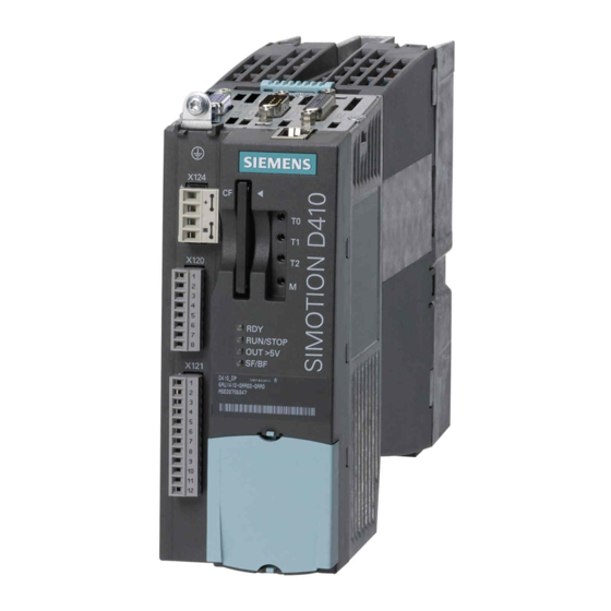
Description 1.3 SIMOTION D410 DP display SIMOTION D410 DP display View The following figure shows SIMOTION D410 DP with the interfaces and front elements. Figure 1-2 Location of interfaces and front elements in SIMOTION D410 DP Note The label underneath the mode selector lists the switch settings for the operating states of the SIMOTION D410. - Page 19 Description 1.3 SIMOTION D410 DP display Interfaces The SIMOTION D410 DP interfaces are described in the following tables. Table 1- 5 SIMOTION D410 interfaces Interface Description Digital inputs/outputs 12-pin Mini Combicon: X121 4 digital inputs: for connecting switches or proximity sensors •...
- Page 20 Description 1.3 SIMOTION D410 DP display The type plate below is located on the front of the SIMOTION D410 DP. Figure 1-4 SIMOTION D410 DP nameplate (example) Note The contents of the individual nameplate fields on the current module may differ from those described in this Manual (e.g., updated product status, space for approvals and identifications, etc.).
-
Page 21: Simotion D410 Pn Display
Description 1.4 SIMOTION D410 PN display SIMOTION D410 PN display View The following figure shows SIMOTION D410 PN with the interfaces and front elements. Figure 1-5 Location of interfaces and front elements in SIMOTION D410 PN D410 Manual, 05/2009... - Page 22 Description 1.4 SIMOTION D410 PN display Interfaces The SIMOTION D410 PN interfaces are described in the following tables. Table 1- 6 SIMOTION D410 interfaces Interface Description Digital inputs/outputs 12-pin Mini Combicon: X121 4 digital inputs: for connecting switches and proximity sensors •...
- Page 23 Description 1.4 SIMOTION D410 PN display The following nameplate includes the MAC address of the PROFINET interface (ports X200 and X201) and is located on the front side of the module. Figure 1-7 SIMOTION PN nameplate (example) Note The contents of the individual nameplate fields on the current module may differ from those described in this Manual (e.g., updated product status, space for approvals and identifications, etc.).
-
Page 24: The Compactflash Card
Description 1.5 The CompactFlash card The CompactFlash card CompactFlash Card The following figure shows you all the information included on the nameplate of the CompactFlash Card (CF card). Figure 1-8 CompactFlash Card Pre-installed runtime licenses For versions V4.1 SP1 HF6 and higher, pre-installed licenses are printed on the type plate of the CF card as a Z option underneath the order number. -
Page 25: Licensing
Description 1.6 Licensing Available Z options / licenses for SIMOTION D CF cards The following Z options are available for SIMOTION D410: TControl temperature control: ● Txx – TControl license and number (e.g. T03 = 3 TControl licenses) SIMOTION IT: ●... -
Page 26: Safety Information
Description 1.7 Safety information Safety information Observe the following safety information when working with SIMOTION D410 and its components! CAUTION The CompactFlash Card may only be unplugged and plugged in when SIMOTION D410 is switched off (zero current)! The SIMOTION D410 is in a de-energized state when all the LEDs are OFF. -
Page 27: Operation (Hardware)
Operation (hardware) Overview of operator controls and indicators The following figure shows the operator controls and indicators arrangement on the SIMOTION D410. Figure 2-1 Operator controls and indicators D410 Manual, 05/2009... -
Page 28: Operator Controls
Operation (hardware) 2.2 Operator controls Operator controls 2.2.1 Service and operating mode switches DIL switches The SIMOTION D410 features operating mode and service selector switches at the bottom of its front side (see Overview of operator controls and indicators (Page 27)). These function using a DIP switch (DIP = Dual In Line Package), where: ●... - Page 29 Operation (hardware) 2.2 Operator controls Mode selector switches The table shows the possible settings for the mode selector switches. Table 2- 1 Mode selector switch settings Operating Description mode SIMOTION D410 runs the user program and all connected system performances: Read process image of inputs.
- Page 30 ● For information on setting the operating modes, refer to the Configuration Manual. Updating ● For information on updating devices (device update tool), refer to the SIMOTION Devices Operating Instructions. ● For information on creating diagnostic data and backing up/restoring non-volatile data, refer to Internet address (http://support.automation.siemens.com/WW/view/en/31237163). D410 Manual, 05/2009...
-
Page 31: Simotion Compactflash Card
Operation (hardware) 2.2 Operator controls 2.2.2 SIMOTION CompactFlash card CompactFlash Card slot The CompactFlash Card (CF card) is inserted into the plug-in module over the blanking plate (see "Overview of operator controls and indicators"). CF card features The CF card is mandatory to run SIMOTION D410. The CF card must be ordered as a separate component;... -
Page 32: Error And Status Indicators
Operation (hardware) 2.3 Error and status indicators Error and status indicators Arrangement of LED displays The LED displays are located under the CF card plug-in slot on the SIMOTION D410 (see the section titled Overview of operator controls and indicators (Page 27)). Further information SIMOTION D410 For the meanings of LED statuses, see the... -
Page 33: Interfaces
Interfaces Overview of interfaces This chapter describes the SIMOTION D410 interfaces. Available interfaces Table 3- 1 Overview of available SIMOTION D410 interfaces Interface Designation Connector type Digital inputs X121 Mini Combicon, 12-pin Digital inputs/outputs X121 Mini Combicon, 12-pin DRIVE-CLiQ interface X100 DRIVE-CLiQ connector PROFIBUS DP interface... -
Page 34: Digital Inputs/Outputs
Interfaces 3.2 Digital inputs/outputs Digital inputs/outputs Sensors and actuators can be connected to the X121 connector via digital inputs and outputs. The following types of digital inputs/outputs are available: ● Digital inputs (4 pcs) ● Bidirectional digital inputs/outputs (4 pcs) Bidirectional digital inputs and outputs can be configured individually as digital inputs or outputs. - Page 35 Interfaces 3.2 Digital inputs/outputs Interface assignments Table 3- 4 Interface assignment X121 View Designation Notes Technical details Voltage: -3 to 30 V • Current input (typical): 10 mA at 24 V DC • Electrical isolation: reference potential is G1 terminal •...
- Page 36 Interfaces 3.2 Digital inputs/outputs Note An open input is interpreted as "low". The G1 terminal must be connected for the digital inputs (DI) 0 to 3 to function. This can be done as follows: • Connect the carried digital input reference ground to M1. •...
- Page 37 Interfaces 3.2 Digital inputs/outputs Wiring and block diagram The following figure shows the wiring and block diagrams of the digital inputs/outputs using the example of a SIMOTION D410 DP. Figure 3-1 Connection example D410 Manual, 05/2009...
- Page 38 Interfaces 3.2 Digital inputs/outputs Digital inputs 4 digital inputs are available on the control unit. The electrically isolated inputs can be used as user-addressable inputs. Switches or proximity encoders (2- or 3-wire encoders) can be connected. The inputs comply with the standard IEC 1131-2/DIN EN 61131-2, characteristic type 2 (24 V P switching).
-
Page 39: Drive-Cliq Interface
Interfaces 3.3 DRIVE-CLiQ interface DRIVE-CLiQ interface Features The DRIVE-CLiQ interface has the following features: ● Automatic detection of components ● For the DRIVE-CLiQ interface, 24 V / 450 mA are available to connect encoders and measuring systems. Interface features Table 3- 5 Interface X100 Features Type... - Page 40 Interfaces 3.3 DRIVE-CLiQ interface Connectable devices The following table contains the components that can communicate with SIMOTION D410 via the DRIVE-CLiQ interface. Note the max. number of nodes that can be connected to the DRIVE-CLiQ! Table 3- 7 DRIVE-CLiQ connection topology Components Max.
- Page 41 Interfaces 3.3 DRIVE-CLiQ interface Figure 3-2 Example topology: 3 terminal modules, 1 encoder via motor with a DRIVE-CLiQ interface, 1 encoder via SMx Figure 3-3 Example topology: 3 terminal modules, 1 CUA31, 1 encoder via motor with DRIVE-CLiQ interface, 1 encoder via SMx D410 Manual, 05/2009...
- Page 42 Interfaces 3.3 DRIVE-CLiQ interface Further information For information on the components that can be connected via DRIVE-CLiQ (setup, connection, configuration, etc.) see SINAMICS S120 Control Units and Additional System Components ● Manual SINAMICS S120 for AC Drives ● Manual SINAMICS S120 ●...
-
Page 43: Profibus Dp Interface (Simotion D410 Dp Only)
Interfaces 3.4 PROFIBUS DP interface (SIMOTION D410 DP only) PROFIBUS DP interface (SIMOTION D410 DP only) SIMOTION D410 DP provides one interface to connect to PROFIBUS DP. The interface can be run asynchronously or isochronously, equidistant. A baud rate of up to 12 Mbps can be set for the PROFIBUS DP interface. SIMOTION D410 includes master and I-slave functionality. - Page 44 Interfaces 3.4 PROFIBUS DP interface (SIMOTION D410 DP only) Note A teleservice adapter can be connected to the PROFIBUS interface (X21) for remote diagnosis. The power supply for the teleservice (terminals 2 and 7) can take up to 150 mA and is sustained short-circuit proof.
-
Page 45: Profinet Interface (Simotion D410 Pn Only)
Interfaces 3.5 PROFINET interface (SIMOTION D410 PN only) PROFINET interface (SIMOTION D410 PN only) PROFINET is an open component-based industrial communication system using Ethernet for distributed automation systems. SIMOTION D410 PN includes a PROFINET interface with 2 ports (X200 and X201). The PROFINET interface supports operation of a SIMOTION D410 PN as an IO controller and/or as an I device. - Page 46 Interfaces 3.5 PROFINET interface (SIMOTION D410 PN only) Connectable devices The following devices can be connected to the PROFINET interface: ● PG/PC programming devices (communication with SIMOTION SCOUT / STEP 7 and HMI) ● SIMATIC HMI devices ● Distributed I/O ●...
-
Page 47: Htl / Ttl / Ssi Encoder Interface
Interfaces 3.6 HTL / TTL / SSI encoder interface HTL / TTL / SSI encoder interface The HTL/TTL/SSI encoder interface is used to connect external encoders. Interface features Table 3- 12 Interface X23 Features Type TTL or HTL incremental encoders (with Encoder interface •... - Page 48 Interfaces 3.6 HTL / TTL / SSI encoder interface Interface assignments Table 3- 13 Interface assignment X23 View Name Description +Temp KTY or PTC input SSI_CLK SSI clock positive SSI_XCLK SSI clock negative P_Encoder 5 V / 24 V Encoder power supply P_Encoder 5 V / 24 V Encoder power supply P_Sence...
-
Page 49: Ep Terminals/Temperature Sensor Connection
Interfaces 3.7 EP terminals/temperature sensor connection EP terminals/temperature sensor connection The EP terminal is the input terminal for SINAMICS Safety Integrated Basic Functions: STO (Safe Torque Off), SS1 (Safe Stop 1) and SBC (Safe Brake Control). For SBC, you also require a Safe Brake Relay. - Page 50 Interfaces 3.7 EP terminals/temperature sensor connection Interface assignments Table 3- 15 Interface assignment X120 View Name Description Reserved, do not use Reserved, do not use Ground + Temp KTY or PTC input - Temp Ground for KTY or PTC Reserved, do not use EP +24 V Safety Integrated Basic Functions (+) EP M1...
-
Page 51: Power Supply
Set the DC power supply to 26 V. This can ensure that the motor holding brake supply voltage is in the permissible range if the following boundary conditions are fulfilled: • You are using a Siemens AC motor. • You are using Siemens Motion-Connect power cables. - Page 52 Interfaces 3.8 Power supply Interface assignments Table 3- 16 Interface X124 View Description Technical details Electronic power supply Voltage: 24 VDC (20.4 V - 28.8 V) Current consumption: max. 0.8 A (without DRIVE-CLiQ and Electronic power supply digital outputs) Electronic ground max.
-
Page 53: Measuring Sockets
Interfaces 3.9 Measuring sockets Measuring sockets Interface features The T0 - T2 measuring sockets are used to output analog signals Any interconnectable signal can be output to any measuring socket on the control unit. Note The measuring sockets are suited for multiple-spring wire connectors with a diameter of 2 mm. -
Page 54: Power Module Interface
Interfaces 3.10 Power Module Interface 3.10 Power Module Interface SIMOTION D410 can be connected to a SINAMICS S120 PM340 blocksize power module via the power module interface. Note SIMOTION D410 can only be connected to a SINAMICS S120 PM340 blocksize power module via the power module interface. -
Page 55: Assembling
Assembling General requirements Mounting options SIMOTION D410 comes in two designs: ● Mounted on the power module: SIMOTION D410 is mounted on the PM340 power module. ● Operation away from the power module: SIMOTION D410 is mounted on a mounting plate. -
Page 56: Simotion D410 Mounted On The Power Module
Assembling 4.2 SIMOTION D410 mounted on the power module SIMOTION D410 mounted on the power module Overview A SIMOTION D410 can be snapped directly on to a SINAMICS S120 PM340 Power Module in blocksize format via the PM-IF interface. Operation with SINAMICS G120 PM2x0 power modules is not possible. - Page 57 Assembling 4.2 SIMOTION D410 mounted on the power module Mounting on the power module Snapping the SIMOTION D410 onto the PM340 PM340 power module with SIMOTION D410 power module D410 Manual, 05/2009...
- Page 58 Assembling 4.2 SIMOTION D410 mounted on the power module Disassembling SIMOTION D410 To remove SIMOTION D410 from the power module, the blue release, as shown in the figure, must be pressed down and SIMOTION D410 tilted forward. Figure 4-1 Removing the SIMOTION D410 from the PM340 power module D410 Manual, 05/2009...
-
Page 59: Mounting Simotion D410 On The Mounting Plate
Assembling 4.3 Mounting SIMOTION D410 on the mounting plate Mounting SIMOTION D410 on the mounting plate Overview Using a mounting plate, SIMOTION D410 can be operated on a mounting plate, which means it is not mounted directly to the power module. Application examples: ●... - Page 60 Assembling 4.3 Mounting SIMOTION D410 on the mounting plate Mounting on mounting plate 1. The mounting plate is attached to the control cabinet. 2. SIMOTION D410 is snapped onto the mounting plate. Figure 4-2 Mounting SIMOTION D410 on the mounting plate Note When operating SIMOTION D410 away from the power module, generally the power supply must be realized via the power supply connection (X124).
-
Page 61: Connecting
Connecting Overview This chapter describes the basic guidelines for the electrical setup. You must observes these guidelines to ensure uninterrupted operation. Safety regulations To safely operate your system, take the following measures and adapt them to your specific conditions: ● An EMERGENCY-OFF concept based on applicable technical specifications (e.g., European Standards EN 60204, EN 418 and associated standards). -
Page 62: General Rules For Operating The Simotion D410
Connecting 5.2 General rules for operating the SIMOTION D410 General rules for operating the SIMOTION D410 You must observe these general rules when integrating the SIMOTION D410 into a system. System startup after certain events The following table identifies considerations required for startup of a system following certain events. - Page 63 Connecting 5.2 General rules for operating the SIMOTION D410 24 V DC supply voltage The following table identifies the considerations required for the 24 V supply voltage. Table 5- 3 24 V DC supply voltage When ... ensure ... Buildings External lightning Provide lightning protection (e.g., protection...
-
Page 64: Overview Of Simotion D410 Connections
Connecting 5.3 Overview of SIMOTION D410 connections Overview of SIMOTION D410 connections Figure 5-1 Overview of connections Connecting the protective ground Connect SIMOTION D410 to the protective ground. An M4 protective ground screw is available (see figure "Location of interfaces and front elements in SIMOTION D410" in Chapter "Description"). -
Page 65: Connecting The Power Supply
Connecting 5.5 Connecting the power supply Connecting the power supply The 24 V DC load power supply required for the supply must be wired to the screw terminal block (connector X124). Note The interface X124 is provided exclusively to connect the external power supply. Properties of the load power supply DANGER The 24 V DC voltage must be generated as functional extra-low voltage with safe electrical... - Page 66 Connecting 5.5 Connecting the power supply Wiring the screw terminal block WARNING Ensure that the system is de-energized when you wire the modules! Use flexible cables with a cross-section of at least 1 mm² when you wire the power supply. Wire-end sleeves are required if you wire several cables per connection.
-
Page 67: Connecting Drive-Cliq Components
Connecting 5.6 Connecting DRIVE-CLiQ components Connecting DRIVE-CLiQ components DRIVE-CLiQ connects the components in the SINAMICS S120 drive family as well as SIMOTION D410. DRIVE-CLiQ is a communications system, which enables SIMOTION D410 to automatically detect connected components. DRIVE-CLiQ provides a wiring tree, the topology of which can be visualized in SIMOTION SCOUT. -
Page 68: Connecting The Digital Inputs/Outputs
Connecting 5.7 Connecting the digital inputs/outputs Connecting the digital inputs/outputs Connecting cables for digital inputs/outputs Use flexible cables with a cross-section of at least 0.25 mm² when you wire the digital inputs/outputs. If you wire two cables per connection, use cables with a cross-section of 0.25 mm² each and a wire-end sleeve. -
Page 69: Connecting The Profibus Dp Interface (410 Dp Only)
Connecting 5.8 Connecting the PROFIBUS DP interface (410 DP only) Connecting the PROFIBUS DP interface (410 DP only) 5.8.1 PROFIBUS connection components Connection components Individual nodes are connected via bus connectors and PROFIBUS cables. Remember to provide a bus connector with a programming port at the ends of the subnet. This provides you with the option to expand the subnet if needed, e.g., with a PG or SIMATIC HMI device. -
Page 70: Profibus Cable Lengths
Connecting 5.8 Connecting the PROFIBUS DP interface (410 DP only) Connector features The bus connector is used to connect the PROFIBUS cable to the PROFIBUS DP interface (X21), thus establishing a connection to additional nodes. You will find an overview of the bus connectors available for order in the chapter titled "Spare parts and accessories". -
Page 71: Rules For Routing Profibus Cables
Connecting 5.8 Connecting the PROFIBUS DP interface (410 DP only) 5.8.4 Rules for routing PROFIBUS cables Routing bus cables When routing the PROFIBUS cable, you must avoid: ● Twisting ● Stretching ● Squeezing Boundary conditions You must pay attention to the following boundary conditions when routing the bus cable for indoor use (dA = external cable diameter): Table 5- 8 Boundary conditions for routing of PROFIBUS cables... -
Page 72: Connecting Profibus Dp (Interface X21)
Connecting 5.8 Connecting the PROFIBUS DP interface (410 DP only) 5.8.5 Connecting PROFIBUS DP (interface X21) Introduction PROFIBUS cables are connected to the corresponding interface via a bus connector. Connecting the bus connector Proceed as follows to connect the bus connector: 1. -
Page 73: Connection Rules In The Profibus Subnet
Connecting 5.8 Connecting the PROFIBUS DP interface (410 DP only) 5.8.6 Connection rules in the PROFIBUS subnet Introduction There are a number of rules for configuring and installing cables for PROFIBUS networks to ensure seamless communication over PROFIBUS. These rules apply to both configuring and cabling as well as address assignment for the different network nodes. - Page 74 Connecting 5.8 Connecting the PROFIBUS DP interface (410 DP only) Networking example The following figure shows an example configuration of a subnet with SIMOTION D410 DP. Figure 5-3 Networking example D410 Manual, 05/2009...
-
Page 75: Connecting The Profinet Interface (410 Pn Only)
Connecting 5.9 Connecting the PROFINET interface (410 PN only) Connecting the PROFINET interface (410 PN only) Information on PROFINET PROFINET is an open component-based industrial communication system using Ethernet (IEC 61158) for distributed automation systems. SIMOTION D410 PN supports the following PROFINET communication methods: ●... -
Page 76: Connecting An External Encoder
Connecting 5.10 Connecting an external encoder 5.10 Connecting an external encoder Connecting the connecting cable Note Use only shielded cables to connect an external encoder to the encoder interface (X23). The shielding must be connected with the metallic or metallized connector housing. The pre-assembled connecting cables offer optimal noise immunity as well as sufficiently measured cross-sections for the supply voltage of the external encoder. -
Page 77: Technical Data
Technical data SIMOTION D410 dimensional diagram Figure 6-1 SIMOTION D410 dimensional diagram D410 Manual, 05/2009... -
Page 78: Simotion D410 Mounting Plate Dimensional Diagram
Technical data 6.2 SIMOTION D410 mounting plate dimensional diagram SIMOTION D410 mounting plate dimensional diagram Dimensions of the SIMOTION D410 mounting plate Figure 6-2 D410 mounting plate D410 Manual, 05/2009... -
Page 79: Cad Data, Dimension Drawings, And Circuit-Diagram Macros
Dimension drawings, as well as 2D and 3D CAD data, can be generated in commonly used formats using CAD CREATOR. For information on how to do this, refer to: Internet address (http://support.automation.siemens.com/WW/view/en/30559271). Circuit-diagram macros EPLAN circuit-diagram macros are available for SIMOTION D410. The macros are supported when you create circuit diagrams. -
Page 80: System Data, Connection Values, Dimensions And Weight
Technical data 6.4 System data, connection values, dimensions and weight System data, connection values, dimensions and weight PLC and motion control performance Table 6- 1 General information Maximum number of axes 1 (real axis) Minimum PROFIBUS cycle 2 ms (D410 DP) Minimum PROFINET transmission cycle 0.5 ms (D410 PN) Minimum servo/interpolator cycle clock... - Page 81 Technical data 6.4 System data, connection values, dimensions and weight Communication Table 6- 5 SIMOTION D410 interfaces DRIVE-CLiQ interface PROFIBUS interface 1 (D410 DP only) Equidistant and isochronous • Can be configured as master or slave • PROFINET interface 1 interface with 2 ports (D410 PN only) Supports PROFINET IO with IRT and RT •...
- Page 82 Technical data 6.4 System data, connection values, dimensions and weight CompactFlash Card Table 6- 8 CF card Memory capacity 512 MB (order no. 6AU1400-2NA00-0AA0) 1 GB (order no. 6AU1400-2PA00-0AA0) Weight 10 g With CF cards, SIMOTION versions up to and including V4.1 SP1 inc. hotfixes support a maximum memory addressing of 512 MB.
-
Page 83: Digital Inputs/Outputs
Technical data 6.5 Digital inputs/outputs Digital inputs/outputs Digital inputs Table 6- 10 Technical data for digital inputs Number of inputs Input voltage Rated value 24 V DC • • At signal "1" 15 to 30 V • • At signal "0" -3 to +5 V •... - Page 84 Technical data 6.5 Digital inputs/outputs Table 6- 13 Digital inputs/outputs when used as output Rated load voltage 24 V DC Permissible range 20.4 to 28.8 V Electrical isolation Current load, max. 500 mA per output Residual current, max. 2 mA 0 →...
-
Page 85: Clock
Technical data 6.6 Clock Clock Features of real-time clock The table below contains the features and functions of the Control Unit clock. Table 6- 14 Clock features Features Description Type Hardware clock (integrated "real-time clock") Default setting when delivered DT#1992-01-01-00:00:00 Maximum deviation per day with supply voltage switched on and switched off at ±9 s... -
Page 86: Mechanical And Climatic Ambient Conditions
Technical data 6.8 Mechanical and climatic ambient conditions Mechanical and climatic ambient conditions Conditions of use SIMOTION D410 is designed for use in stationary, weather-protected locations. The conditions of use exceed the requirements of the environmental test according to DIN IEC 60068-2-2. SIMOTION D410 meets the conditions of use, Class 3C3, according to DIN EN 60721-3-3 (operating locations with high traffic densities and in the immediate vicinity of industrial equipment with chemical emissions). - Page 87 Technical data 6.8 Mechanical and climatic ambient conditions Table 6- 16 Mechanical ambient conditions Ambient conditions Operation Transport (in packaging) Vibration tested in 10 to 57 Hz: 0.35 mm 5 to 9 Hz: 3.5 mm accordance with DIN EN 58 to 200 Hz: 50 m/s² 9 to 200 Hz: 10 m/s²...
-
Page 88: Specifications For Dielectric Tests, Safety Class And Degree Of Protection
Technical data 6.9 Specifications for dielectric tests, safety class and degree of protection Specifications for dielectric tests, safety class and degree of protection Test voltages Insulation resistance is verified with a routine test with the following test voltage according to IEC 61131-2: Table 6- 18 Test voltages... -
Page 89: Spare Parts/Accessories
Spare parts/Accessories Terminal module TM31 Features of the TM31 The TM31 terminal module allows you to expand the number of available digital inputs/outputs as well as the number of analog inputs/outputs within a drive system. The TM31 is connected via DRIVE-CLiQ. It has 2 DRIVE-CLiQ interfaces for this. The TM31 contains the following terminals: Table 7- 1 Interface overview of the TM31... -
Page 90: Terminal Module Tm41
Spare parts/Accessories 7.2 Terminal module TM41 Terminal module TM41 Features of the TM41 The TM41 terminal module allows you to expand the number of available digital inputs/outputs as well as the number of analog inputs within a drive system. In addition, it enables the use of the TTL output for encoder simulation. -
Page 91: Tm54F Terminal Module
Spare parts/Accessories 7.3 TM54F terminal module TM54F terminal module Features of the TM54F The TM54F Terminal Module is a terminal expansion module for snapping on to a DIN EN 60715 mounting rail. The TM54F offers safe digital inputs and outputs for controlling SINAMICS Safety Integrated functions and is supported by SIMOTION D410, V4.1 SP2 and higher. -
Page 92: Terminal Modules Tm15 And Tm17 High Feature
Spare parts/Accessories 7.4 Terminal modules TM15 and TM17 High Feature Terminal modules TM15 and TM17 High Feature Features of TM15 and TM17 High Feature The TM15 and TM17 High Feature terminal modules are used to implement inputs of measuring inputs and outputs of output cams for SIMOTION D. In addition, these terminal modules provide drive-related digital inputs and outputs with short signal delay times. - Page 93 Spare parts/Accessories 7.4 Terminal modules TM15 and TM17 High Feature Note CAUTION The 50 mm clearances above and below the components must be observed. Additional references You will find further information on TM15 and TM17 High Feature in the Supplementary SINAMICS System Components for SIMOTION ●...
-
Page 94: Cua31/Cua32 Control Unit Adapter
Spare parts/Accessories 7.5 CUA31/CUA32 control unit adapter CUA31/CUA32 control unit adapter Features of the CUA31/CUA32 You can connect a blocksize power module to the DRIVE-CLiQ interface using the CUA31 adapter module. The CUA32 adapter module also provides an encoder interface for an HTL, TTL or SSI encoder. -
Page 95: Dmc20 Drive-Cliq Hub
Spare parts/Accessories 7.6 DMC20 DRIVE-CLiQ hub DMC20 DRIVE-CLiQ hub Features The DRIVE-CLiQ hub module 20 (DMC20) is used for the star-shaped distribution of a DRIVE-CLiQ cable. The module is especially suitable for applications which require DRIVE-CLiQ link nodes to be removed in groups, without interrupting the DRIVE-CLiQ link cable and therefore the data exchange. -
Page 96: List Of Spare Parts And Accessories
D410 is described in the D410 Commissioning Manual. Spares On Web Spares On Web is an information system that enables you to find out which spare parts can be ordered for your device. To find out more, go to: Internet address (http://workplace.automation.siemens.de/sparesonweb). D410 Manual, 05/2009... -
Page 97: Standards And Approvals
EN 61000-6-2 UL certification Recognized component mark for United States and the Canada Underwriters Laboratories (UL) according to Standard UL 508, File 16 4110. Declaration of conformity The current Declaration of Conformity is on the Internet at http://support.automation.siemens.com/WW/view/de/15257461 D410 Manual, 05/2009... -
Page 98: Safety Of Electronic Controllers
Standards and approvals A.2 Safety of electronic controllers Safety of electronic controllers Introduction The following remarks relate to fundamental criteria and apply irrespective of the type of controller and the manufacturer. Reliability Comprehensive and cost-effective measures have been taken during development and production to increase the reliability of the devices and components as far as possible. - Page 99 Standards and approvals A.2 Safety of electronic controllers Division into safety-critical and non-safety-critical areas Nearly all systems contain parts that perform safety-related tasks (e.g. emergency stop switch, protective grating, two-hand controls). To avoid having to apply safety-related criteria to the entire controller, it is customary to divide the controller into two areas - one that is critical to safety and one that is not critical to safety.
-
Page 100: Electromagnetic Compatibility
Standards and approvals A.3 Electromagnetic Compatibility Electromagnetic Compatibility Definition Electromagnetic compatibility (EMC) is the ability of an electrical device to function sufficiently in its electromagnetic environment without interfering with this environment. The SIMOTION D410 control meets the requirements of the EU directive on EMC and the EMC law of the European single market 89/339/EEC. -
Page 101: Esd Directives
ESD directives ESD definition What does ESD mean? All electronic modules are equipped with highly integrated modules or components. Because of the technology used, these electronic components are very sensitive to overvoltages and thus to discharge of static electricity. The acronym ESD has become the established designation for such Electrostatic Sensitive Devices. - Page 102 ESD directives B.2 Electrostatic charging of individuals Electrostatic charging of individuals Any person who is not conductively connected to the electrical potential of the environment can accumulate an electrostatic charge. This figure indicates the maximum electrostatic charges that can accumulate on an operator when he comes into contact with the indicated materials.
- Page 103 ESD directives B.3 Basic measures for protection against discharge of static electricity Basic measures for protection against discharge of static electricity Ensure sufficient grounding When working with electrostatic sensitive devices, make sure that the you, your workstation, and the packaging are properly grounded. This prevents the accumulation of static electricity.
- Page 105 Index Connection example Digital inputs/outputs, 37 Connection rules, 73 Accessories, 96 CUA31/CUA32, 94 DRIVE-CLiQ hub module (DMC20), 95 TM15, 92 Declaration of conformity, 97 TM15 DI/DO, 92 Diagnostic buffer, 80 TM17 High Feature, 92 Digital input, 38 TM31, 89 Digital input/digital output, 38 TM41, 90 Connecting cables, 68 TM54F, 91...
- Page 106 Index Mounting plate Data, 82 Guideline Dimensional diagram, 78 ESD, 101 MRES, 29 HTL / TTL / SSI encoder interface, 47 Operator control, 27 I/O integration, 16 Performance IEC 1131, 97 PLC and motion control, 80 Indicator, 27 PLC and motion control Installation, 56, 59 Performance, 80 Installing on the Power Module, 56...
- Page 107 Index STOPU, 29 Storage conditions, 85 Subnet Connection rules, 73 Switch settings, 28 Technical data Clock, 85 Digital input/digital output, 83 General information, 80 Temperature sensor connection, 49 Terminal Module TM15, 92 TM15 DI/DO, 92 TM17 High Feature, 92 TM31, 89 TM41, 90 TM54F, 91 Terminating resistor, 69...
- Page 108 SIMOTION SIMOTION SCOUT D410 Manual, 05/2009...
Need help?
Do you have a question about the SIMOTION SCOUT D410 and is the answer not in the manual?
Questions and answers