Siemens SIMOTION D410 Manual
Hide thumbs
Also See for SIMOTION D410:
- Commissioning manual (230 pages) ,
- Manual (110 pages) ,
- Manual (108 pages)
Table of Contents
Advertisement
Advertisement
Table of Contents

Related Manuals for Siemens SIMOTION D410


Summary of Contents for Siemens SIMOTION D410
- Page 1 Preface Description Operation (hardware) SIMOTION Interfaces D410 Assembling Connecting Manual Technical data Spare parts/Accessories Standards and approvals ESD directives Appendix Valid for SIMOTION D410 DP and D410 PN 03/2007 Edition...
- Page 2 Trademarks All names identified by ® are registered trademarks of the Siemens AG. The remaining trademarks in this publication may be trademarks whose use by third parties for their own purposes could violate the rights of the owner.
-
Page 3: Preface
This section explains how you configure a mechanical layout and install the SIMOTION D410 in a control cabinet. • Connecting This chapter describes how to connect and network the SIMOTION D410. • Technical data This chapter describes the properties and features of the SIMOTION D410. - Page 4 A&D Technical Support: • Phone: +49 (180) 50 50 222 • Fax: +49 (180) 50 50 223 • E–mail: adsupport@siemens.com • Internet: http://www.siemens.de/automation/support-request If you have any questions, suggestions, or corrections regarding the documentation, please fax or e-mail them to: •...
- Page 5 Nuremberg, phone +49 (911) 895 3202. Disposal and recycling SIMOTION D410 is an environmentally friendly product! It includes the following features: • In spite of its excellent resistance to fire, the flame-resistant agent in the plastic used for the housing does not contain halogens.
-
Page 7: Table Of Contents
Error and status indicators ......................26 Interfaces..............................27 Overview of interfaces .........................27 Digital inputs/outputs........................28 DRIVE-CLiQ interface........................32 PROFIBUS DP interface (SIMOTION D410 DP only) ..............35 PROFINET interface (SIMOTION D410 PN only) ...............37 HTL/TTL encoder interface ......................38 EP terminals/temperature sensor connection................39 Power supply..........................40 Measuring sockets ........................42... - Page 8 Connection rules in the PROFIBUS subnet ................58 5.10 Connecting an external encoder ....................60 Technical data ............................61 SIMOTION D410 dimensional diagram ..................61 System data, connection values, dimensions and weight ............62 Digital inputs/outputs........................63 Shipping and storage conditions....................64 Mechanical and climatic ambient conditions................
- Page 9 SIMOTION D410 interfaces ......................18 Table 1-6 SIMOTION D410 interfaces ......................21 Table 2-1 Mode selector switch settings ......................24 Table 3-1 Overview of available SIMOTION D410 interfaces..............27 Table 3-2 Overview of non-usable SIMOTION D410 interfaces..............27 Table 3-3 Interface X121..........................28 Table 3-4 Interface assignment X121 ......................29 Table 3-5 Interface X100..........................32...
- Page 10 Table of contents Table 6-2 SIMOTION D410 electrical connection values................62 Table 6-3 SIMOTION D410 dimensions and weight ................... 62 Table 6-4 CF card............................62 Table 6-5 Digital input technical data ......................63 Table 6-6 Digital output technical data ......................63 Table 6-7 Shipping and storage conditions....................
-
Page 11: Description
In SIMOTION D, the SIMOTION functionality is integrated directly in the closed-loop control module of the SINAMICS S120 drive system. SIMOTION D410 is a module drive system for single axes, which solves demanding drive tasks for a very wide range of industrial applications. SIMOTION D410 supplements D425, D435 and D445, the three power levels for multi-axis connections. - Page 12 Description 1.1 System overview System integration SIMOTION provides an optimized system platform for automation and drive solutions where the main focus is on motion control applications and technology tasks. The SIMOTION system is made up of three components: • SIMOTION SCOUT Engineering System •...
-
Page 13: System Components
Power supply (PS) ... provides the electronic power supply for SIMOTION D410, e.g., SITOP. Note: If SIMOTION D410 is to be mounted on the power module, the power is supplied via the power module (e.g., PM340). The digital outputs of SIMOTION D410 are not supplied by the power supply. -
Page 14: Table 1-2 Components On Profibus Dp
Other controls (e.g., SIMOTION or SIMATIC) Note Note that only a real axis can be used on a SIMOTION D410! Note Please note that not all modules for the I/O systems listed above are enabled for SIMOTION. Moreover, system-related functional differences can come into play when these I/O or I/O systems are used on SIMOTION vs. -
Page 15: Table 1-3 Components On Profinet
For modules enabled for SIMOTION (e.g., S7-300 module FM 350-1, etc.), these driver modules are part of the SIMOTION SCOUT Engineering System command library. PROFINET SIMOTION D410 PN can communicate via PROFINET interface to the following components: Table 1-3 Components on PROFINET... -
Page 16: Table 1-4 Components On Drive-Cliq
Description 1.2 System components DRIVE-CLiQ SIMOTION D410 can communicate via DRIVE-CLiQ interface to the following components: Table 1-4 Components on DRIVE-CLiQ Components Function Drive units ... convert speed setpoints into signals for controlling the motor SINAMICS S120 AC DRIVE and supply the power required to operate the motors. The (with CUA31) AC DRIVE component PM340 is connected via CUA31. -
Page 17: Simotion D410 Dp Display
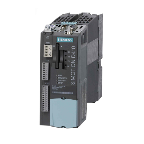
Description 1.3 SIMOTION D410 DP display SIMOTION D410 DP display View The following figure shows SIMOTION D410 DP with the interfaces and front elements. Figure 1-2 Location of interfaces and front elements in SIMOTION D410 DP Note The lettering "DP ADDRESS" below the DIL switch is of no interest. -
Page 18: Table 1-5 Simotion D410 Interfaces
Description 1.3 SIMOTION D410 DP display Interfaces The SIMOTION D410 DP interfaces are described in the following tables. Table 1-5 SIMOTION D410 interfaces Interface Description 4 digital inputs: Socket to connect switches or proximity sensors Digital inputs/outputs • X121 4 digital inputs/outputs: 12-pin socket to connect actuators and •... - Page 19 Description 1.3 SIMOTION D410 DP display The following nameplate includes the SIMOTION D410 DP barcode numbers and is located on the front side of the module. Figure 1-4 SIMOTION D410 DP nameplate (example) Note The contents of the individual nameplate fields on the current module may differ from those described in this Manual (e.g., updated product status, approvals and identifications not yet...
-
Page 20: Simotion D410 Pn Display
Description 1.4 SIMOTION D410 PN display SIMOTION D410 PN display View The following figure shows SIMOTION D410 PN with the interfaces and front elements. Figure 1-5 Location of interfaces and front elements in SIMOTION D410 PN Note The lettering "DP ADDRESS" below the DIL switch is of no interest. -
Page 21: Table 1-6 Simotion D410 Interfaces
Description 1.4 SIMOTION D410 PN display Interfaces The SIMOTION D410 PN interfaces are described in the following tables. Table 1-6 SIMOTION D410 interfaces Interface Description 4 digital inputs: Socket to connect switches and proximity Digital inputs/outputs • sensors X121 4 digital inputs/outputs: 12-pin socket to connect actuators and •... -
Page 22: Safety Information
Observe the following safety information when working with SIMOTION D410 and its components! Caution The CompactFlash card may only be unplugged and plugged in when SIMOTION D410 is switched off (zero current)! Caution The 50 mm clearances above and below the components must be observed. The ventilation openings may not be covered by connecting cables. -
Page 23: Operation (Hardware)
Operation (hardware) Overview of operator controls and indicators The following figure shows the operator controls and indicators arrangement on the SIMOTION D410. Figure 2-1 Operator controls and indicators The operator controls and indicators are described below. D410 Manual, 03/2007 Edition... -
Page 24: Operator Controls
Mode selector switch DIL switches The mode selector switch function is realized in SIMOTION D410 by a DIL switch (DIL = Dual In Line Package). The DIL switch is located in the lower front area of the SIMOTION D410 (see "Overview of operator controls and indicators"). -
Page 25: Simotion Compactflash Card
Use the SIMOTION SCOUT Engineering System to set the operating mode (at switch setting 1110000). Switches S4 - S7 are not used in SIMOTION D410 and must be set to "0" (OFF). SIMOTION SCOUT mode selector switch In SIMOTION SCOUT, you can control the SIMOTION D410 operating state using a software switch. -
Page 26: Error And Status Indicators
System data, connection values, dimensions and weight (Page 62) Error and status indicators Arrangement of LED displays The LED displays are located under the CF card plug-in module on the SIMOTION D410 (see "Overview of operator controls and indicators"). Further information... -
Page 27: Interfaces
Interfaces Overview of interfaces This chapter describes the SIMOTION D410 interfaces. Available interfaces Table 3-1 Overview of available SIMOTION D410 interfaces Interface Designation Connector type Digital inputs X121 12-pin socket Digital inputs/outputs X121 12-pin socket DRIVE-CLiQ interface X100 DRIVE-CLiQ connector... -
Page 28: Digital Inputs/Outputs
Interfaces 3.2 Digital inputs/outputs Digital inputs/outputs Sensors and actuators can be connected to the X121 connector via digital inputs and outputs. The following types of digital inputs/outputs are available: • Digital inputs (4 pcs) • Bidirectional digital inputs/outputs (4 pcs) Bidirectional digital inputs and outputs can be configured individually as digital inputs or outputs. -
Page 29: Table 3-4 Interface Assignment X121
Interfaces 3.2 Digital inputs/outputs Interface assignments Table 3-4 Interface assignment X121 View Designation Description Technical details Voltage: -3 to 30 V • Current input (typical): 10 mA at 24 V DC • Electrical isolation: reference potential is G1 terminal • Level (including ripple): •... - Page 30 Interfaces 3.2 Digital inputs/outputs Wiring and block diagram The following figure shows the wiring and block diagrams of the digital inputs/outputs on the SIMOTION D410. Figure 3-1 Connection example D410 Manual, 03/2007 Edition...
- Page 31 (24 V P switching). Bidirectional digital inputs/outputs 4 digital inputs/outputs (DI/DO) are available on the SIMOTION D410. The following application options are available when configuring the DI/DO as digital inputs: • DI/DO9, 10 and 11 can be used as "fast inputs" for measuring inputs.
-
Page 32: Drive-Cliq Interface
Interfaces 3.3 DRIVE -CLiQ interface DRIVE-CLiQ interface Features The DRIVE-CLiQ interface has the following features: • Automatic detection of components • For the DRIVE-CLiQ interface, 24 V / 450 mA are available to connect encoders and measuring systems. Interface features Table 3-5 Interface X100 Features... -
Page 33: Table 3-7 Drive-Cliq Connection Topology
Interfaces 3.3 DRIVE -CLiQ interface Connectable devices The following table contains the components that can communicate with SIMOTION D410 via the DRIVE-CLiQ interface. Note the max. number of nodes that can be connected to the DRIVE-CLiQ! Table 3-7 DRIVE-CLiQ connection topology Components Max. - Page 34 Interfaces 3.3 DRIVE -CLiQ interface Figure 3-3 Example topology: 3 terminal modules, 1 CUA31, 1 encoder via SMI, 1 encoder via SMC Further information For information on the components that can be connected via DRIVE-CLiQ (setup, connection, configuration, etc.) see SINAMICS S120 Control Units and Supplementary System Components Equipment •...
-
Page 35: Profibus Dp Interface (Simotion D410 Dp Only)
3.4 PROFIBUS DP interface (SIMOTION D410 DP only) PROFIBUS DP interface (SIMOTION D410 DP only) SIMOTION D410 DP provides one interface to connect to PROFIBUS DP. The interface can be run asynchronously or isochronously, equidistant. A baud rate of 12 Mbits/s can be set for the PROFIBUS DP interface. - Page 36 Interfaces 3.4 PROFIBUS DP interface (SIMOTION D410 DP only) PROFIBUS connector The terminating resistors must be switched on at the first and last terminal in a line to ensure uninterrupted communication. The bus terminating resistors are activated in the connector.
-
Page 37: Profinet Interface (Simotion D410 Pn Only)
PROFINET is an open component-based industrial communication system using Ethernet for distributed automation systems. SIMOTION D410 PN includes a PROFINET interface with 2 ports (X200 and X201). A SIMOTION D410 PN can be set as IO controller or I device via the PROFINET interface. Interface features Table 3-10... -
Page 38: Htl/Ttl Encoder Interface
Interfaces 3.6 HTL/TTL encoder interface HTL/TTL encoder interface The HTL-/TTL encoder interface is used to connect external encoders (HTL or TTL encoders). Interface features Table 3-12 Interface X23 Features Type Connector type: 15-pin D-Sub connector Encoder interface: TTL/HTL incremental encoder Limiting frequency: 500 kHz TTL encoder: 100 m (bipolar signals only) -
Page 39: Ep Terminals/Temperature Sensor Connection
Interfaces 3.7 EP terminals/temperature sensor connection EP terminals/temperature sensor connection The EP terminal is the input terminal for the "safe standstill" and is wired to the motor module. The "safe standstill" is activated, if the EP terminal on the motor module is activated at the same time as the terminal X121 (DI) on the control unit. -
Page 40: Power Supply
The 24 V DC load power supply is required for the supply • of digital inputs/outputs (X121) • SIMOTION D410 can be supplied with power by connecting a power module. Additional 24 V must be connected in the following situations: –... -
Page 41: Table 3-16 Interface X124
Interfaces 3.8 Power supply Interface assignments Table 3-16 Interface X124 View Description Technical details Electronic power supply Voltage: 24 V DC (20.4 V - 28.8 V) Current consumption: max. 0.8 A (without DRIVE-CLiQ and Electronic power supply digital outputs) Electronic ground max. -
Page 42: Measuring Sockets
SIMOTION D410 can be connected to a blocksize power module via the power module interface. Note SIMOTION D410 can only be connected to a blocksize power module via the power module interface. You must connect a chassis power module via the DRIVE-CLiQ interface (see chapter "Connecting DRIVE-CLiQ Components"). -
Page 43: Assembling
Open device SIMOTION D410 is an open device! This means, you can only install the modules in housings, cabinets or electrical equipment rooms. These may only be accessible via key or tool. Housings, cabinets, or electrical equipment rooms may only be accessed by trained or authorized personnel. - Page 44 Assembling 4.2 SIMOTION D410 mounted on the power module Requirement As soon as the power module (e.g., PM340) is properly installed, you can mount the SIMOTION D410 to the power module. Note Take note of the associated user documentation when commissioning the power module!
- Page 45 Assembling 4.2 SIMOTION D410 mounted on the power module Disassembling SIMOTION D410 To remove SIMOTION D410 from the power module, the blue release, as shown in the figure, must be pressed down and SIMOTION D410 tilted forward. Figure 4-1 Removing the SIMOTION D410 from the power module (e.g., PM340)
-
Page 46: Mounting Simotion D410 On The Mounting Plate
4.3 Mounting SIMOTION D410 on the mounting plate Mounting SIMOTION D410 on the mounting plate Overview Using a mounting plate, SIMOTION D410 can be operated on a mounting plate, which means it is not mounted directly to the power module. Requirements You must order the mounting plate for SIMOTION D410 separately. -
Page 47: Connecting
As an additional resource on the topic of EMC guidelines, we recommend the description EMC installation guidelines, engineering instructions (HW) , /15/. Standards and specifications You must comply with the applicable VDE guidelines when wiring the SIMOTION D410, in particular VDE 0100 and VDE 0113 for disconnecting devices, short-circuit and overload protection. D410... -
Page 48: General Rules For Operating The Simotion D410
5.2 General rules for operating the SIMOTION D410 General rules for operating the SIMOTION D410 You must observe these general rules when integrating the SIMOTION D410 into a system. System startup after certain events The following table identifies considerations required for startup of a system following certain events. -
Page 49: Table 5-4 Protection Against External Electrical Interference
Connecting 5.2 General rules for operating the SIMOTION D410 Danger The 24 V DC voltage must be designed as functional extra-low voltage with safe isolation (PELV according to DIN EN 60204-1). Protection against external electrical interference The following table identifies the considerations required for electrical interference or failures. -
Page 50: Overview Of Simotion D410 Connections
2. Connect the protective ground and screw the protective ground screw back into the insert nut (Torx screwdriver, size 25). Caution Always ensure the connection to the protective ground is low resistance. If SIMOTION D410 is mounted on a movable frame, you must provide a flexible cable to the protective ground. D410... -
Page 51: Connecting The Power Supply
Connecting 5.5 Connecting the power supply Connecting the power supply The 24 V DC load power supply required for the supply must be wired to the screw terminal block (connector X124). Note The interface X124 is provided exclusively to connect the external power supply. Properties of the load power supply Danger The 24 V DC voltage must be generated as functional extra-low voltage with safe electrical... -
Page 52: Connecting Drive-Cliq Components
• For a motor module, the power cable for the motor and the associated motor encoder must be connected. Connecting DRIVE-CLiQ components Connect the X100 socket on SIMOTION D410 with the corresponding socket on the drive components via the DRIVE-CLiQ signal cable (motor module, TM and SMC modules). Note... -
Page 53: Connecting The Digital Inputs/Outputs
Connecting 5.7 Connecting the digital inputs/outputs Connecting the digital inputs/outputs Connecting cables for digital inputs/outputs Use flexible cables with a cross-section of at least 0.25 mm² when you wire the digital inputs/outputs. If you wire two cables per connection, use cables with a cross-section of 0.25 mm² each and a wire-end sleeve. -
Page 54: Connecting The Profinet Interface (410 Pn Only)
Connecting the PROFINET interface (410 PN only) Information on PROFINET PROFINET is an open component-based industrial communication system using Ethernet (IEC 61158) for distributed automation systems. SIMOTION D410 PN supports the following PROFINET communication methods: • RT • IRT top • IRT flex... -
Page 55: Connecting The Profibus Dp Interface (410 Dp Only)
Connecting 5.9 Connecting the PROFIBUS DP interface (410 DP only) Connecting the PROFIBUS DP interface (410 DP only) 5.9.1 Connection components in PROFIBUS Connection components Individual nodes are connected via bus connectors and PROFIBUS cables. Remember to provide a bus connector with a programming port at the ends of the subnet. This provides you with the option to expand the subnet if needed, e.g., with a PG or SIMATIC HMI device. -
Page 56: Profibus Cable Lengths
Connecting 5.9 Connecting the PROFIBUS DP interface (410 DP only) Connector features The bus connector is used to connect the PROFIBUS cable to the PROFIBUS DP interface (X21), which is how you establish the connection to additional nodes. You will find an overview of the bus connectors available for order in chapter "Spare parts and accessories". -
Page 57: Connecting Profibus Dp (Interface X21)
Connecting 5.9 Connecting the PROFIBUS DP interface (410 DP only) Boundary conditions You must pay attention to the following boundary conditions when routing the bus cable for indoor use (dA = external cable diameter): Table 5-8 Boundary conditions for routing of PROFIBUS cables Features Boundary conditions Bending radius for a single bend... -
Page 58: Connection Rules In The Profibus Subnet
Connecting 5.9 Connecting the PROFIBUS DP interface (410 DP only) Removing the bus connector You can remove the bus connector with a looped-through PROFIBUS cable from the PROFIBUS DP interface at any time, without interrupting data traffic on the bus. Warning Data traffic error might occur on the bus! A bus segment must always be terminated at both ends with the terminating resistor. - Page 59 PROFIBUS DP connector at the first and last node and switching off the other terminating resistors. Networking example The following figure shows an example configuration of a subnet with SIMOTION D410 DP. Figure 5-3 Networking example...
-
Page 60: Connecting An External Encoder
Connecting 5.10 Connecting an external encoder 5.10 Connecting an external encoder Connecting the connecting cable Note Use only shielded cables to connect an external encoder to the encoder interface (X23). The shielding must be connected with the metallic or metallized connector housing. The pre-assembled connecting cables offer optimal noise immunity as well as sufficiently measured cross-sections for the supply voltage of the external encoder. -
Page 61: Technical Data
Technical data SIMOTION D410 dimensional diagram Figure 6-1 SIMOTION D410 dimensional diagram D410 Manual, 03/2007 Edition... -
Page 62: System Data, Connection Values, Dimensions And Weight
Memory for system data and its memory size Data Memory size Diagnostic buffer 200 messages Connection values Table 6-2 SIMOTION D410 electrical connection values Supply voltage 24 V DC (permissible range: 20,4 ... 28.8 V) Power consumption from 24 V Basic configuration typically 0.8 A Power loss... -
Page 63: Digital Inputs/Outputs
Technical data 6.3 Digital inputs/outputs Digital inputs/outputs Digital inputs (according to IEC 1131-2/DIN EN 61131-2, characteristic type 2) Table 6-5 Digital input technical data Number of inputs 4 DI 4 DI/DO (configured as DI) Supply voltage 24 V DC 0 signal: -3 to 5 V Input voltage •... -
Page 64: Shipping And Storage Conditions
DIN IEC 60068-2-2. SIMOTION D410 meets the conditions of use, Class 3C3, according to DIN EN 60721-3-3 (operating locations with high traffic densities and in the immediate vicinity of industrial equipment with chemical emissions). -
Page 65: Table 6-8 Mechanical Ambient Conditions
• Shock load: DIN EN 60721-3-3, Class 3M4 • Free fall: DIN EN 60721-3-2, Class 2M1 and 2M2 • Toppling: DIN EN 60721-3-2, Class 2M1 The mechanical ambient conditions for SIMOTION D410 are listed in the following table in the form of sinusoidal vibrations. Table 6-8... -
Page 66: Specifications For Dielectric Tests, Safety Class And Degree Of Protection
Technical data 6.6 Specifications for dielectric tests, safety class and degree of protection Specifications for dielectric tests, safety class and degree of protection Test voltages Insulation resistance is verified with a routine test with the following test voltage according to IEC 61131-2: Table 6-10 Test voltages... -
Page 67: Spare Parts/Accessories
Spare parts/Accessories Terminal module TM31 Features of the TM31 The TM31 terminal module allows you to expand the number of available digital inputs/outputs as well as the number of analog inputs/outputs within a drive system. The TM31 is connected via DRIVE-CLiQ. It has 2 DRIVE-CLiQ interfaces for this. The TM31 contains the following terminals: Table 7-1 Interface overview of the TM31... -
Page 68: Terminal Module Tm41
Spare parts/Accessories 7.2 Terminal module TM41 Terminal module TM41 Features of the TM41 The TM41 terminal module allows you to expand the number of available digital inputs/outputs as well as the number of analog inputs within a drive system. In addition, it enables the use of the TTL output for encoder simulation. -
Page 69: Terminal Modules Tm15 And Tm17 High Feature
Spare parts/Accessories 7.3 Terminal modules TM15 and TM17 High Feature Terminal modules TM15 and TM17 High Feature Features of TM15 and TM17 High Feature The TM15 and TM17 High Feature terminal modules are used to implement inputs of measuring inputs and outputs of output cams for SIMOTION D. In addition, these terminal modules provide drive-related digital inputs and outputs with short signal delay times. -
Page 70: Cua31 Control Unit Adapter
Spare parts/Accessories 7.4 CUA31 control unit adapter CUA31 control unit adapter Features of the CUA31 The control unit adapter 31 (CUA31), combined with a modular power module, is used to expand an existing DC/AC group. You can connect a blocksize power module to the DRIVE- CLiQ interface using the CUA31 adapter module. -
Page 71: Dmc20 Drive-Cliq Hub
Spare parts/Accessories 7.5 DMC20 DRIVE-CLiQ hub DMC20 DRIVE-CLiQ hub Features The DRIVE-CLiQ hub module 20 (DMC20) is used for the star-shaped distribution of a DRIVE-CLiQ cable. The module is especially suitable for applications which require DRIVE-CLiQ link nodes to be removed in groups, without interrupting the DRIVE-CLiQ link cable and therefore the data exchange. -
Page 72: List Of Spare Parts And Accessories
Weidmüller M4 screw-on shield connection Weidmüller M4/1.8 Nm protective ground terminal Mounting plate for operation away from the power module 6AU1 400-7AA05-0AA0 Spare fan for SIMOTION D410 6SL3 064-0AC00-0AA0 CompactFlash Card 6AU1 400-2NA00-0AA0 Bus connection up to 12 Mbit/s, 90° cable outlet:... -
Page 73: Standards And Approvals
UL certification Recognized component mark for United States and the Canada Underwriters Laboratories (UL) in accordance with UL 508, File 16 4110. Declaration of conformity The current Declaration of Conformity is on the Internet at http://support.automation.siemens.com/WW/view/de/15257461 D410 Manual, 03/2007 Edition... -
Page 74: Safety Of Electronic Controllers
Standards and approvals A.2 Safety of electronic controllers Safety of electronic controllers Introduction The remarks made here relate to fundamental criteria and apply irrespective of the type of controller and the manufacturer. Reliability The reliability of devices and components is maintained at the highest possible level thanks to comprehensive and cost-effective measures implemented during the development and manufacturing processes. -
Page 75: Electromagnetic Compatibility
Electromagnetic compatibility (EMC) is the ability of an electrical device to function sufficiently in its electromagnetic environment without interfering with this environment. The SIMOTION D410 control meets the requirements of the EU directive on EMC and the EMC law of the European single market 89/339/EEC. -
Page 77: Esd Directives
ESD directives ESD definition What does ESD mean? All electronic modules are equipped with highly integrated modules or components. Because of the technology used, these electronic components are very sensitive to overvoltages and thus to discharge of static electricity. The acronym ESD has become the established designation for such Electrostatic Sensitive Devices. -
Page 78: Electrostatic Charging Of Individuals
ESD directives B.2 Electrostatic charging of individuals Electrostatic charging of individuals Any person who is not conductively connected to the electrical potential of the environment can accumulate an electrostatic charge. This figure indicates the maximum electrostatic charges that can accumulate on an operator when he comes into contact with the indicated materials. -
Page 79: Appendix
Appendix References The following documents are part of the documentation package, SIMOTION D4xx. SIMOTION D410, Commissioning Manual This documentation is part of the SIMOTION D4xx documentation package and is included in the SIMOTION SCOUT scope of delivery. Edition 03/2007 SINAMICS S120 Control Units and Supplementary System... - Page 80 Appendix C.1 References Motion Control System SIMOTION, PM10 Catalog, Order documentation Order no.: E86060-K4910-A101-A5 Automation Systems for Machine Tools, NC60 Catalog, Order documentation Order no.: E86060-K4460-A101-B1 SIMATIC Automation System S7-300, Module Data, Reference Manual This documentation is part of the documentation package with Order number: 6ES7 398-8FA10-8AA0 Edition 02/2004 SIMATIC NET, Industrial Twisted Pair and Fiber Optic Networks,...
-
Page 81: List Of Abbreviations
Appendix C.2 List of abbreviations List of abbreviations Table C-1 Abbreviations Abbreviation Description ASIC Application Specific Integrated Circuit CF card CompactFlash Card Control Unit Adapter Digital-to-analog converter DESINA Decentralized and standardized installation technology for machine tools and manufacturing systems Digital Input Dual In Line Package Digital Output Distributed I/O... - Page 82 Appendix C.2 List of abbreviations Abbreviation Description Software TCP/IP Transmission Control Protocol / Internet Protocol Totally Integrated Automation Terminal Module for DRIVE-CLiQ Technology object Technology package Transistor Transistor Logic D410 Manual, 03/2007 Edition...
-
Page 83: Index
57 IEC 1131, 73 Indicators, 23 Identifier, 73 Installation Climatic ambient conditions, 65 SIMOTION D410 on the mounting plate, 46 CompactFlash Card SIMOTION D410 on the power module, 44 Slot, 25 Interfaces Conditions of use, 64... - Page 84 Shipping conditions, 64 SIMOTION D410 Product variants, 11 Spare parts, 72 Storage conditions, 64 Nameplates Subnet SIMOTION D410 DP, 18 Connection components, 55 SIMOTION D410 PN, 21 Connection rules, 58 Segment, 55 Terminating resistor, 55 System integration, 12 Operator controls, 23...
Need help?
Do you have a question about the SIMOTION D410 and is the answer not in the manual?
Questions and answers