WAGO Kontakttechnik GmbH & Co. KG, Minden. Non-observance will en- tail the right of claims for damages. WAGO Kontakttechnik GmbH & Co. KG reserves the right of changes serv- ing technical progress. All rights developing from the issue of a patent or the legal protection of util- ity patents are reserved to WAGO Kontakttechnik GmbH &...
Important Notes • 7 Standards and Regulations for Operating the 750 Series improper action and damage to WAGO products and third party products due to non-observance of the information contained in this manual. 1.1.3 Conforming Use of Series 750 The couplers and controllers of the modular I/O System 750 receive digital and analog signals from the I/O modules and sensors and transmit them to the actuators or higher level control systems.
Note Make important notes that are to be complied with so that a trouble-free and efficient device operation can be guaranteed. Additional Information References to additional literature, manuals, data sheets and INTERNET pages. WAGO-I/O-SYSTEM 750 DeviceNet...
Danger The WAGO-I/O-SYSTEM 750 and its components are an open system. It must only be assembled in housings, cabinets or in electrical operation rooms. Access is only permitted via a key or tool to authorized qualified per- sonnel.
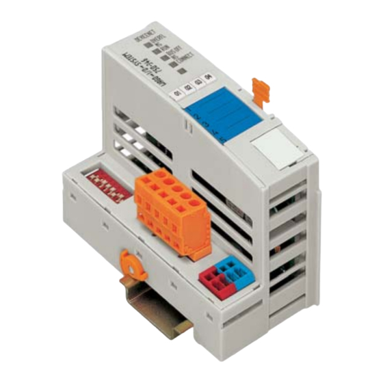
Binary '100' Within ', '0110.0100' Nibble separated with dots 1.7 Scope This manual describes the modular WAGO-I/O-SYSTEM 750 with the DeviceNet ECO fieldbus coupler. Item-No. Description 750-346 DeviceNet ECO fieldbus coupler, 125 kBaud ... 500 kBaud; digital and analog signals...
Input/Output Identifier, Identification Index ISO/ OSI International Organization for Standardization / Open Systems Interconnection (model) High Byte Hardware Low Byte MAC ID Media Access Control Identifier (nodeaddress) Module Status Network Management Network Status Read Only Read/Write Software WAGO-I/O-SYSTEM 750 DeviceNet...
ECO coupler and the bus modules is carried out via an internal bus. The WAGO-I/O-SYSTEM 750 has a clear port level with LEDs for status in- dication, insertable mini WSB markers and pullout group marker carriers. The 3-wire technology supplemented by a ground wire connection allows for direct sensor/actuator wiring.
The WAGO-I/O-SYSTEM 750 • 13 Technical Data 2.2 Technical Data Mechanic Material Polycarbonate, Polyamide 6.6 Dimensions - ECO coupler - 50 mm x 65* mm x 100 mm - I/O module, single - 12 mm x 64* mm x 100 mm...
Page 14
14 • The WAGO-I/O-SYSTEM 750 Technical Data Mechanical strength Vibration resistance acc. to IEC 60068-2-6 Comment to the vibration restistance: a) Type of oscillation: sweep with a rate of change of 1 octave per minute 10 Hz ≤ f < 57 Hz, const. Amplitude 0,075 mm 57 Hz ≤...
Page 15
Germany, the Federal Office for Post and Telecommunications and its branch offices issues the permit. It is possible to use other field bus couplers / controllers under certain boundary condi- tions. Please contact WAGO Kontakttechnik GmbH. Maximum power dissipation of the components Bus modules 0.8 W / bus terminal (total power dissipation, sys-...
16 • The WAGO-I/O-SYSTEM 750 Manufacturing Number Dimensions Side view Dimensions in mm Fig. 2-2: Dimensions g0xxx15e 2.3 Manufacturing Number The manufacturing number indicates the delivery status directly after produc- tion. This number is part of the lateral marking on the component.
18 • The WAGO-I/O-SYSTEM 750 Storage, Assembly and Transport 2.5 Storage, Assembly and Transport Wherever possible, the components are to be stored in their original packag- ing. Likewise, the original packaging provides optimal protection during transport. When assembling or repacking the components, the contacts must not be soiled or damaged.
European standard EN 50022 (DIN 35). Warning WAGO supplies standardized carrier rails that are optimal for use with the I/O system. If other carrier rails are used, then a technical inspection and ap- proval of the rail by WAGO Kontakttechnik GmbH should take place.
The WAGO-I/O-SYSTEM 750 • 21 Mechanical Setup 2.6.5 Plugging and Removal of the Components Warning Before work is done on the components, the voltage supply must be turned off. In order to safeguard the ECO coupler from jamming, it should be fixed onto the carrier rail with the locking disc.
22 • The WAGO-I/O-SYSTEM 750 Mechanical Setup 2.6.6 Assembly Sequence All system components can be snapped directly on a carrier rail in accordance with the European standard EN 50022 (DIN 35). The reliable positioning and connection is made using a tongue and groove system.
The WAGO-I/O-SYSTEM 750 • 23 Mechanical Setup 2.6.7 Internal Bus / Data Contacts Communication between the ECO coupler and the bus modules as well as the system supply of the bus modules is carried out via the internal bus. It is com- prised of 6 data contacts, which are available as self-cleaning gold spring con- tacts.
Fig. 2-8: Example for the arrangement of power contacts g0xxx05e Recommendation With the WAGO ProServe® Software smartDESIGNER, the assembly of a fieldbus node can be configured. The configuration can be tested via the inte- grated accuracy check. WAGO-I/O-SYSTEM 750...
26 • The WAGO-I/O-SYSTEM 750 Power Supply 2.7 Power Supply 2.7.1 Isolation Within the fieldbus node, there are three electrically isolated potentials. • Operational voltage for the fieldbus interface. • Electronics of the ECO coupler and the bus modules (internal bus).
2.7.2 System Supply 2.7.2.1 Connection The WAGO-I/O-SYSTEM 750 requires a 24 V direct current system supply (-15% or +20 %). The power supply is provided via the ECO coupler and, if necessary, in addition via the internal system supply modules (750-613). The voltage supply is reverse voltage protected.
28 • The WAGO-I/O-SYSTEM 750 Power Supply Attention Resetting the system by switching on and off the system supply, must take place simultaneously for all supply modules (ECO coupler and 750-613). 2.7.2.2 Alignment Recommendation A stable network supply cannot be taken for granted always and everywhere.
Page 29
• 29 Power Supply Recommendation With the WAGO ProServe® Software smartDESIGNER, the assembly of a fieldbus node can be configured. The configuration can be tested via the inte- grated accuracy check. The maximum input current of the 24 V system supply is 260 mA. The exact...
30 • The WAGO-I/O-SYSTEM 750 Power Supply 2.7.3 Field Supply 2.7.3.1 Connection Sensors and actuators can be directly connected to the relevant channel of the bus module in 1-/4 conductor connection technology. The bus module supplies power to the sensors and actuators. The input and output drivers of some bus modules require the field side supply voltage.
The WAGO-I/O-SYSTEM 750 • 31 Power Supply By inserting an additional power supply module, the field supply via the power contacts is disrupted. From there a new power supply occurs which may also contain a new voltage potential. Attention Some bus modules have no or very few power contacts (depending on the I/O function).
Page 32
32 • The WAGO-I/O-SYSTEM 750 Power Supply Warning In the case of power supply modules with fuse holders, only fuses with a maximum dissipation of 1.6 W (IEC 127) must be used. For UL approved systems only use UL approved fuses.
Page 33
The WAGO-I/O-SYSTEM 750 • 33 Power Supply Alternatively, fusing can be done externally. The fuse modules of the WAGO series 281 and 282 are suitable for this purpose. Fig. 2-18: Fuse modules for automotive fuses, Series 282 pf66800x Fig. 2-19: Fuse modules with pivotable fuse carrier, Series 281 pe61100x Fig.
34 • The WAGO-I/O-SYSTEM 750 Power Supply 2.7.4 Supply example Note The system supply and the field supply should be separated in order to ensure bus operation in the event of a short-circuit on the actuator side. 750-612 750-410 750-401...
• 35 Power Supply 2.7.5 Power Supply Unit The WAGO-I/O-SYSTEM 750 requires a 24 V direct current system supply with a maximum deviation of -15% or +20 %. Recommendation A stable network supply cannot be taken for granted always and everywhere.
The optimal insulated setup is a metallic assembly plate with grounding con- nection with an electrical conductive link with the carrier rail. The separate grounding of the carrier rail can be easily set up with the aid of the WAGO ground wire terminals. Article No. Description...
The WAGO-I/O-SYSTEM 750 • 37 Grounding 2.8.2 Grounding Function The grounding function increases the resistance against disturbances from electro-magnetic interferences. Some components in the I/O system have a carrier rail contact that dissipates electro-magnetic disturbances to the carrier rail. Fig. 2-22: Carrier rail contact...
38 • The WAGO-I/O-SYSTEM 750 Grounding 2.8.3 Grounding Protection For the field side, the ground wire is connected to the lowest connection ter- minals of the power supply module. The ground connection is then connected to the next module via the Power Jumper Contact (PJC). If the bus module has...
Note For better shield performance, the shield should have previously been placed over a large area. The WAGO shield connection system is suggested for such an application. This suggestion is especially applicable when the equipment can have even current or high impulse formed currents running through it (for example through atmospheric end loading).
Assembly Guidelines / Standards 2.9.4 WAGO Shield (Screen) Connecting System The WAGO Shield Connecting system includes a shield clamping saddle, a collection of rails and a variety of mounting feet. Together these allow many dfferent possibilities. See catalog W4 volume 3 chapter 10.
Setting the MAC ID and Baud Rate ..........54 3.1.7.3 Configuration with Static Assembly ..........55 3.1.8 LED Display ..................59 3.1.8.1 Node status – Blink code from the 'I/O' LED ....... 60 3.1.9 Technical Data ................... 67 WAGO-I/O-SYSTEM 750 DeviceNet...
The bits of the digital modules are sent byte by byte and added to the analog data. If the amount of digital information exceeds 8 bits, the bus- coupler automatically starts with a new byte. WAGO-I/O-SYSTEM 750 DeviceNet...
• Display elements (LED's) for status display of the operation, the bus com- munication, the operating voltages as well as for fault messages and diag- nosics • Configuration interface • Electronics for communication with the I/O modules (internal bus) and the fieldbus interface WAGO-I/O-SYSTEM 750 DeviceNet...
(Open Style Connector). The scope of delivery includes the plug connector 231-305/010-000/050-000 from the WAGO MULTI CONNECTION SYSTEM. The connector has gold plated contacts and has the signal designations printed at its clamping units.
Fieldbus coupler is ready for operation. BUS OFF Error or malfunction at network CONNECT green Fieldbus coupler is ready for network communication. red/ The ‚I/O‘-LED indicates the operation of the node and signals faults green/ encountered. orange WAGO-I/O-SYSTEM 750 DeviceNet...
Fieldbus Coupler • 47 Fieldbus Coupler 750-346 3.1.2.5 Configuration Interface The configuration interface used for the communication with WAGO-I/O-CHECK or for firmware transfer is located behind the cover flap. open flap Configuration interface Fig. 3-5: Configuration interface g01xx06e The communication cable (750-920) is connected to the 4 pole header.
In the event of a fault the coupler changes to the "Stop" condition. The "I/O" LED flashes red. After clearing the fault and cycling power, the coupler changes to the "Fieldbus start" status and the "I/O" LED lights up green. Fig. 3-8: Operating system - Power on g012113e WAGO-I/O-SYSTEM 750 DeviceNet...
A process image restructuring may result if a node is changed or extended. In this case the process data addresses also change in comparison with earlier ones. In the event of adding a module, take the process data of all previous modules into account. WAGO-I/O-SYSTEM 750 DeviceNet...
An Output-Assembly writes data to the application or consumes data from the network respectively. Various Assembly instances are permanently programmed (static assembly) in the fieldbus coupler. Further information The Assembly instances for the static assembly are described in chapter "4.5.1.1Assembly Instance". WAGO-I/O-SYSTEM 750 DeviceNet...
(32 bytes each). 1 The input module data can be read from the fieldbus side. 2 In the same manner, writing to the output modules is possible from the fieldbus side. WAGO-I/O-SYSTEM 750 DeviceNet...
A process image restructuring may result if a node is changed or extended. In this case the process data addresses also change in comparison with earlier ones. In the event of adding a module, take the process data of all previous modules into account. WAGO-I/O-SYSTEM 750 DeviceNet...
Page 53
Output process image: Default process data, output image (Assembly Class, Instance 1) Byte low byte channel 1 high byte channel 1 low byte channel 2 high byte channel 2 not used DO04 DO03 DO02 DO01 DO = Digital Output WAGO-I/O-SYSTEM 750 DeviceNet...
To enable a connection between the PLC and the fieldbus devices, the inter- face modules have to be configured with the individual station data. To this effect, the scope of delivery of WAGO-I/O-SYSTEM 758 includes the WAGO NETCON software intended for design and configuration, start-up and diagnosis.
1. Starting Software and EDS file load 6. Start the configuration software WAGO NETCON. 7. Load an EDS file for the fieldbus coupler in WAGO NETCON, i. e. "750- 346.EDS". For this click on "File/ Copy EDS" and choose the EDS-file to load.
Page 56
3. Take the Master into the right-hand window by clicking on the "Add" but- ton and confirm by clicking on the "OK" button. Now the fieldbus master is shown on the surface as a graphic. WAGO-I/O-SYSTEM 750 DeviceNet...
Page 57
4. Take this into the right-hand window by clicking on the "Add" button and confirm by clicking on the "OK" button. The configuration is displayed on the surface as a graphic. Fig. 3-16: Configuration p012504d WAGO-I/O-SYSTEM 750 DeviceNet...
Page 58
Fig. 3-17: Device Configuration p012506d 6. Load Configuration To load the set configuration in the interface card, click on the master’s graphic to mark it, then click on the “Download” menu point in the "On- line" menu. WAGO-I/O-SYSTEM 750 DeviceNet...
A minor fault has occurred. critical link failure The device has detected a fault. It is unable to per- form any more functions in the network. Table 3-2: Fault and status displays: NS WAGO-I/O-SYSTEM 750 DeviceNet...
The third blink sequence (approx. 1 Hz) follows after a further pause. The number of blink pulses indicates the fault argument. Fig. 3-19: Signalling the LED's node status g012111e After overcoming a fault, restart the coupler by cycling the power. WAGO-I/O-SYSTEM 750 DeviceNet...
Page 61
I/O mod- ules and turn the power supply on again Error occurred when writing to Turn off the power supply of the serial EEPROM node, exchange fieldbus coupler and turn the power supply on again. WAGO-I/O-SYSTEM 750 DeviceNet...
Page 62
Fault argument Fault description Trouble shooting Process image not activ Access on invalid process image. Please contact the WAGO I/O- Support (Note the version number and the configuration) Prozess image is larger than size Reduce the number of I/O modules...
Page 63
I/O module is detected. Replace the faulty I/O module. If there is only one I/O module left but the LED is still blinking, then this I/O module or the coupler is defective. Replace defective com- ponent. WAGO-I/O-SYSTEM 750 DeviceNet...
Page 64
Replace defective com- ponent. Interruption of the internal bus Turn off the power supply of the after the n process data module. node, exchange the (n+1) process data module and turn the power supply on again. WAGO-I/O-SYSTEM 750 DeviceNet...
Page 65
Reduce the data width of the exceeded due to the put Gateway Gateway modules. modules * The number of blink pulses (n) indicates the position of the I/O module. I/O modules without data are not counted (e.g. supply module without diagnosis) WAGO-I/O-SYSTEM 750 DeviceNet...
Page 66
4 (internal bus data fault). The third blink sequence follows the second pause. The "I/O " LED blinks twelve times. The fault argument 12 means that the internal bus is interrupted after the 12th I/O module. WAGO-I/O-SYSTEM 750 DeviceNet...
E175199, UL508 DEMKO 02 ATEX 132273 X II 3 GD EEx nA II T4 Conformity marking Accessories EDS files Download: www.wago.com Miniature WSB quick marking system Technical data Max. number of I/O modules Fieldbus Input process image max. 32 Byte Output process image max.
A transmitting DeviceNet node produces data that is either consumed via a point-to-point connection (1 to 1) by one receiving node, or via a multicast connection (1 to n) by several receiving nodes. WAGO-I/O-SYSTEM 750 DeviceNet...
The length of the individual drop lines is measured from the branching point of the node and can be up to 6 m. The entire length of the drop line depends on the Baud rate. WAGO-I/O-SYSTEM 750 DeviceNet...
(worst case). 4.2.2 Cabling The connection of a WAGO fieldbus node to the DeviceNet bus cable is made by the supplied 5-pole plug (Multi Connector 231). Fieldbus...
Page 71
A low Ohm connection of the screening on PE terminal can only be made externally. Note WAGO offers the screen connection system (series 790) for an optimum con- nection between fieldbus cable screening and functional earth. Each DeviceNet node forms the differential voltage U...
For this purpose, the bus cable has to be looped without interruption. A maximum length of 6 m for a drop line should not be ex- ceeded. The following is a topology example: Power Supply WAGO-I/O-SYSTEM 750 DeviceNet...
4.2.5 Interface Modules In a network, all WAGO DeviceNet fieldbus nodes are delivered to operate as slaves. The master operation is taken over by a central control system, such as PLC, NC or RC.
(attributes) or resetting a class. • Behaviour: The behaviour defines how a device reacts as a consequence of external events, such as changed process data, or as a consequence of internal events, such as expiring timers. WAGO-I/O-SYSTEM 750 DeviceNet...
The data field consists of the service identification and the destina- tion address. The format of the explicit messages is defined. Via explicit mes- sages devices can be configured or a dynamic built-up of message connections can be made. WAGO-I/O-SYSTEM 750 DeviceNet...
The desired process image can be selected by setting the Produced Connection Path and the Consumed Connection Path of the individual I/O connections (Poll, Bit Strobe, Change of State or Change of Value). The architecture of the individual instances of the assembly object is described in the following. WAGO-I/O-SYSTEM 750 DeviceNet...
Input 1 (I/O Assembly Instance 7): The entire input data image is transmitted to the master via the corresponding I/O message connection. The data length is equivalent to the number of input data in byte. WAGO-I/O-SYSTEM 750 DeviceNet...
Page 78
Input 3 (I/O Assembly Instance 9): The analog input data image is transmitted to the master via the corresponding I/O message connection. The data length is equivalent to the number of analog input data in bytes. WAGO-I/O-SYSTEM 750 DeviceNet...
ODVA informs about the EDS files of all listed manufacturers. http://www.odva.org EDS and symbol files to configure the I/O modules are available under the order numberr 750-912 on a floppy disk or on the WAGO INTERNET home- page. http://www.wago.com WAGO-I/O-SYSTEM 750...
750-346 optional Heartbeat USINT The nominal interval between Interval heartbeat messages in seconds Services: Service Code Service Name Description 0x0E Get_Attribute_Single Returns the contents of the specified attribute 0x05 Reset Invokes the reset service for the device WAGO-I/O-SYSTEM 750 DeviceNet...
Page 82
Used to modify a DeviceNet object attribute value 0x4B Allocate_Master/Slave_Connection Requests the use of the predefined Master/Slave connection 0x4C Release_Group_2_Identifier_Set Indicates that the specified connections within the predefined Master/Slave connection set are no longer desired. These connections are to be released (deleted) WAGO-I/O-SYSTEM 750 DeviceNet...
Page 83
Instance 4: Attribute Used in Access Name Data type Description Value buscoupler rule dep. on kind Process Array of process image, collection of all of connected image Byte modules process input data plus modules status byte. WAGO-I/O-SYSTEM 750 DeviceNet...
Page 84
+ Byte analog modules process input data modules Error plus Error Code (Cl. 100/Inst. 1/ Code + Attr. 45) Error plus Error Argument (Cl. 100/Inst. Argument 1/ Attr. 46) WAGO-I/O-SYSTEM 750 DeviceNet...
Page 85
Instance ID Description References the Explicit Messaging Connection into the Server References the Poll I/O Connection References Bit-Strobe I/O Connection References the Slave´s Change of State or Cyclic I/O Connection Reserved for „Reserved Identifier“, Message ID 1 WAGO-I/O-SYSTEM 750 DeviceNet...
Page 86
USINT State of the object required instance_ USINT Indicates either I/O or Messaging Connection type required transport- USINT Defines behaviour of the connection Class_ trigger required produced_ UINT CAN Identifier field when the connection WAGO-I/O-SYSTEM 750 DeviceNet...
Page 87
USINT Defines the message groups across which tial_comm productions and consumptions associated _character with this connection occur istics required pro- UINT maximum number of Bytes transmitted across duced_con this connection WAGO-I/O-SYSTEM 750 DeviceNet...
Page 88
Bytes received across sumed_co this connection nnec- tion_size required get/set UINT defines timing associated with this connnec- pected_pa tion cket_rate 10-11 not used required watch- USINT defines how to handle inactivity/watchdog dog timeo timeouts WAGO-I/O-SYSTEM 750 DeviceNet...
Page 89
Waiting for Get_Atribute/ Apply_Atributes Configuring Set_Attribute/ Connection ID Apply_Attributes Apply_Atributes Get_Atribute/ Established Set_Attribute/ Apply_Attributes/ Reset/Message Inactivity/Watchdog Produced/Consumed Timeout & watchdog_timeout_action = Reset Transition to Time Out Delete Timed Out Fig. 4-1: Status of I/O Connection Objects g012546x WAGO-I/O-SYSTEM 750 DeviceNet...
Page 90
UINT Revision of the Coupler Configu- 0x01 ration Object, Range 1-65535, class definition upon which the implementation is based. required UINT maximum instance number of an 0x01 instance object currently created in this class level of device WAGO-I/O-SYSTEM 750 DeviceNet...
Page 91
15: Status (C 100, I 1 A 5) plus three bytes, which are always zero plus analog and digital input data specific get/set BK_SEL_S UINT Non volatile power up value for the polled I/O TORED_PO consumed connection path. The attribute is WAGO-I/O-SYSTEM 750 DeviceNet...
Page 92
1: If possible, fully reset the CAN chip and continue communicating upon detectionof a bus-off indication specific get/set BK_DO_FA USINT Defines the behavior after de allocation the ULT_REAC polled I/O connection TION_ON_ 0: (default) do nothing WAGO-I/O-SYSTEM 750 DeviceNet...
Page 93
PI_LIMIT – 0xFFFE: These values These values cannot be set and led to fault messages. The adjusted value become only on valid with next switching. specific get/set BK_FIXED_C USIN Fixed width of the ConsumedConnectionSize ONS_SIZE (output data) WAGO-I/O-SYSTEM 750 DeviceNet...
Page 94
Used in Access Name Data type Description Value buscoupler rule dep. on kind DIPOBJ_ digital input bit 0:off of connected VALUE 1:on modules Services: Service Code Service Name Description 0x0E Get_Attribute_Single Used to read an object attribute value. WAGO-I/O-SYSTEM 750 DeviceNet...
Page 95
Description of the instances: Instance ID Description reference to the first analog input point reference to the next analog input point reference to the last possible analog input point WAGO-I/O-SYSTEM 750 DeviceNet...
Page 96
USINT output data length number of connected VALUE of Bytes modules Services: Service Code Service Name Description 0x0E Get_Attribute_Single Used to read a DeviceNet Object attribute value 0x10 Set_Attribute_Single Used to modify a DeviceNet object attribute value WAGO-I/O-SYSTEM 750 DeviceNet...
Page 97
Bit 15: 0/1 Analog/Digital module, For analog modules the bits 1-14 describe the type of module i. e. 460 for the module 750-460 Services: Service Code Service Name Description 0x0E Get_Attribute_Single Used to read a DeviceNet Object attribute value WAGO-I/O-SYSTEM 750 DeviceNet...
(Item-no.: 0888-0412) or on the web pages: www.wago.com Service Download Documentation. More Information Current information on the modular WAGO-I/O-SYSTEM is available in the Internet under: www.wago.com 5.1.1 Digital Input Modules DI DC 5 V 750-414 4 Channel, DC 5 V, 0.2 ms, 2- to 3-conductor connection,...
Page 99
750-425, 753-425 2 Channel, NAMUR, Proximity switch acc. to DIN EN 50227 750-438 2 Channel, NAMUR EEx i, Proximity switch acc. to DIN EN 50227 DI Intruder Detection 750-424, 753-424 2 Channel, DC 24 V, Intruder Detection WAGO-I/O-SYSTEM 750 DeviceNet...
2 Channel, DC 0 - 10 V, 10 Bit, 100 mW, 24 V 750-559, 753-559 4 Channel, DC 0 - 10 V AO DC ± 10 V 750-556, 753-556 2 Channel, DC ± 10 V 750-557, 753-557 4 Channel, DC ± 10 V WAGO-I/O-SYSTEM 750 DeviceNet...
Field Side Connection Module, AC/DC 0 ... 230 V Separation Modules 750-616 Separation Module 750-621 Separation Module with Power Contacts Binary Spacer Module 750-622 Binary Spacer Module End Module 750-600 End Module, to loop the internal bus WAGO-I/O-SYSTEM 750 DeviceNet...
(without word alignment). The internal mapping method for data greater than one byte conforms to the Intel format. The following section describes the process image for various WAGO-I/O-SYSTEM 750 and 753 I/O modules when using a DeviceNet cou- pler/controller. Note...
Page 106
Output Process Image Bit 7 Bit 6 Bit 5 Bit 4 Bit 3 Bit 2 Bit 1 Bit 0 Acknowl- Acknowl- edgement bit edgement bit Channel 2 Channel 1 And the input modules seize 4 Instances in Class (0x66). WAGO-I/O-SYSTEM 750 DeviceNet...
1 Channel Digital Output Module with Input Process Data 750-523 Input Process Image Bit 7 Bit 6 Bit 5 Bit 4 Bit 3 Bit 2 Bit 1 Bit 0 Status bit „Manual used Operation“ The output modules seize 2 Instances in Class (0x65). WAGO-I/O-SYSTEM 750 DeviceNet...
Page 108
Output Process Image Bit 7 Bit 6 Bit 5 Bit 4 Bit 3 Bit 2 Bit 1 Bit 0 controls controls DO 2 DO 1 Channel 2 Channel 1 And the output modules seize 2 Instances in Class (0x66). WAGO-I/O-SYSTEM 750 DeviceNet...
Page 109
When an output fault condition occurs (i.e., overload, short circuit, or broken wire), a diagnostic bit is set. The diagnostic data is mapped into the Input Process Image, while the output control bits are in the Output Process Image. WAGO-I/O-SYSTEM 750 DeviceNet...
Page 110
S tic bit S 7 tic bit S 0 Channel Channel Channel Channel Channel Channel Channel Channel Diagnostic bit S = ‘0’ no Error Diagnostic bit S = ‘1’ overload, short circuit, or broken wire WAGO-I/O-SYSTEM 750 DeviceNet...
(Class 0x67). 1 Channel Analog Input Module 750-491, (and all variations) Input Process Image Instance Byte Destination Remark Measured Value U Measured Value U The input modules represent 2x2 bytes and seize 2 Instances in Class (0x67). WAGO-I/O-SYSTEM 750 DeviceNet...
Page 112
753-453, -455, -457, -459 Input Process Image Instance Byte Destination Remark Measured Value Channel 1 Measured Value Channel 2 Measured Value Channel 3 Measured Value Channel 4 The input modules represent 4x2 bytes and seize 4 Instances in Class (0x67). WAGO-I/O-SYSTEM 750 DeviceNet...
I/O Modules 5.2.5 Specialty Modules WAGO has a host of Specialty I/O modules that perform various functions. With individual modules beside the data bytes also the control/status byte is mapped in the process image. The control/status byte is required for the bi- directional data exchange of the module with the higher-ranking control sys- tem.
Page 115
Instance Byte Destination Remark Control byte not used Counter Setting Value of Counter 1 Counter Setting Value of Counter 2 And the specialty modules represent 1x6 bytes output data and seize 1 In- stance in Class (0x68). WAGO-I/O-SYSTEM 750 DeviceNet...
Page 116
The two channel values are supplied as 16 bits. Each channel has its own control/status byte. The following table illustrates the Input and Output Process Image, which has a total of 6 bytes mapped into each image. WAGO-I/O-SYSTEM 750 DeviceNet...
Page 117
Input and Output Process Image Instance Byte Destination Remark Control/Status byte Data bytes The specialty modules represent 2x2 bytes input and output data and seize 2 Instances in Class (0x67) and 2 Instances in Class (0x68). WAGO-I/O-SYSTEM 750 DeviceNet...
Page 118
750-630 (and the variations /000-001, -002, -006, -008, -009, -011, -012, -013) The above SSI Transmitter Interface modules have a total of 4 bytes of user data in the Input Process Image, which has 4 bytes mapped into the image. WAGO-I/O-SYSTEM 750 DeviceNet...
Page 119
Process Image, which have 6 bytes into each image. Input Process Image Instance Byte Destination Remark Status byte Counter word not used Latch word The specialty modules represent 1x6 bytes input data and seize 1 Instance in Class (0x67). WAGO-I/O-SYSTEM 750 DeviceNet...
Page 120
The specialty modules represent 1x6 bytes input data and seize 1 Instance in Class (0x67). Output Process Image Instance Byte Destination Remark Control byte Counter Setting word not used And the specialty modules represent 1x6 bytes output data and seize 1 In- stance in Class (0x68). WAGO-I/O-SYSTEM 750 DeviceNet...
Page 121
Output Process Image (4 bytes of module data and 1 byte of control/status and 1 byte ID for command). The following table illustrates the Input and Output Process Image, which have 6 bytes mapped into each image. WAGO-I/O-SYSTEM 750 DeviceNet...
Page 122
Output Process Image Instance Byte Destination Remark Control byte DALI command, DSI dimming value DALI address Parameter 2 Parameter 1 Command-Extension And the specialty modules represent 1x6 bytes output data and seize 1 Instance in Class (0x68). WAGO-I/O-SYSTEM 750 DeviceNet...
Page 123
The MP Bus Master Module has a total of 8 bytes of user data in both the In- put and Output Process Image (6 bytes of module data and 2 bytes of con- trol/status). The following table illustrates the Input and Output Process Im- age, which have 8 bytes mapped into each image. WAGO-I/O-SYSTEM 750 DeviceNet...
Page 125
Not used Mailbox (0,6, 10, 12 or 18 bytes) / Process data (0-32 bytes) The specialty modules represent 1x 12...48 bytes input and output data and seize 1 Instance in Class (0x67) and 1 Instance in Class (0x68). WAGO-I/O-SYSTEM 750 DeviceNet...
Data bit Data bit DI 8) DI 7) DI 6) DI 5) DI 4) DI 3) DI 2 DI 1 The Binary Space Modules seize 2, 4, 6 or 8 Instances in class (0x65) or in class (0x66). WAGO-I/O-SYSTEM 750 DeviceNet...
Device providing services within a client/server sys- Server tem. The service is requested by the Client. A portion of a network that shares the same network Subnet address as the other portions. These subnets are dis- tinguished through the subnet mask. WAGO-I/O-SYSTEM 750 DeviceNet...
Konrad Etschberger 2., völlig überarbeitete Auflage 2000 Carl Hanser Verlag München Wien ISBN 3-4446-19431-2 Further information on web pages: The ODVA provides further documentation on DeviceNet. www.odva.org CAN in Automation (CiA) provides further documentation on CAN. can-cia.de WAGO-I/O-SYSTEM 750 DeviceNet...
Need help?
Do you have a question about the I/O System 750 Series and is the answer not in the manual?
Questions and answers