Table of Contents
Advertisement
RTU303xC
SIMATIC
TeleControl - RTU
RTU303xC
Operating Instructions
RTU3030C
RTU3031C
06/2019
C79000-G8976-C382-06
Preface
Application and functions
LEDs, connectors, buttons,
card slots
Connecting up, installation,
commissioning
Configuration (WBM)
Program blocks
Diagnostics and
maintenance
Technical data
Approvals
Dimension drawings
Accessories
Syslog Messages
Documentation references
1
2
3
4
5
6
7
A
B
C
D
E
Advertisement
Table of Contents

Related Manuals for Siemens Simatic RTU303xC Series


Summary of Contents for Siemens Simatic RTU303xC Series
- Page 1 RTU303xC Preface Application and functions LEDs, connectors, buttons, card slots SIMATIC Connecting up, installation, commissioning TeleControl - RTU RTU303xC Configuration (WBM) Program blocks Operating Instructions Diagnostics and maintenance Technical data Approvals Dimension drawings Accessories Syslog Messages Documentation references RTU3030C RTU3031C 06/2019 C79000-G8976-C382-06...
- Page 2 Note the following: WARNING Siemens products may only be used for the applications described in the catalog and in the relevant technical documentation. If products and components from other manufacturers are used, these must be recommended or approved by Siemens. Proper transport, storage, installation, assembly, commissioning, operation and maintenance are required to ensure that the products operate safely and without any problems.
-
Page 3: Preface
Preface CAUTION To prevent injury, read the manual before use. Validity of this manual This manual is valid for the products: SIMATIC RTU3030C Article number: 6NH3112-3BA00-0XX0 Hardware product version 2 Firmware version 3.1 The RTU is used to monitor and control outlying stations that are geographically distributed and not connected to a power supply network. - Page 4 Preface The RTU is used to monitor and control outlying stations that are geographically distributed and not connected to a power supply network. The RTU can store process data and transfer it via mobile wireless or via the LAN interface and an external router to a master station. The RTU3031C also has 4 additional digital outputs and supports GPS positioning and time synchronization.
- Page 5 Preface The manaul supports you when installing, connecting up and commissioning the device. The required configuration steps for the device are described. You will also find instructions for operation and information about the diagnostics options. Required experience To install, commission and operate the device, you require experience in the following areas: ●...
-
Page 6: Operating Instructions, 06/2019, C79000-G8976-C382
Link: (https://support.industry.siemens.com/cs/ww/en/ps/21767/pm) Replaced edition Edition 07/2018 Current manual release on the Internet You will also find the current version of this manual on the Internet pages of Siemens Industry Online Support: Link: (https://support.industry.siemens.com/cs/ww/en/ps/21767/man) Cross references In this manual there are often cross references to other sections. - Page 7 Siemens contact. Keep to the local regulations. You will find information on returning the product on the Internet pages of Siemens Industry Online Support: Link: (https://support.industry.siemens.com/cs/ww/en/view/109479891)
- Page 8 Preface Link: (https://support.industry.siemens.com/cs/ww/en/view/50305045) Training, Service & Support You will find information on training, service and support in the multilanguage document "DC_support_99.pdf" on the Internet pages of Siemens Industry Online Support: Link: (https://support.industry.siemens.com/cs/ww/en/view/38652101) RTU303xC Operating Instructions, 06/2019, C79000-G8976-C382-06...
-
Page 9: Table Of Contents
Table of contents Preface ..............................3 Application and functions ........................15 Application and use of the RTU ....................15 Configuration examples ......................17 Modes and operating modes ....................21 Process connection - inputs / outputs ..................24 Control functions ........................24 Communications services ....................... - Page 10 Table of contents 3.8.2 HART devices ........................81 Commissioning and starting up the RTU ................84 Configuration (WBM) ..........................89 Security recommendations ....................89 Range of functions of the WBM ..................... 92 General functions of the WBM ....................94 Permitted characters and parameter lengths ................. 95 Permissible file size for certificates and keys ..............
- Page 11 Table of contents 4.16.1 Overview ..........................150 4.16.2 VPN ............................151 4.16.3 HTTPS ..........................156 4.16.4 Event buffer ........................... 159 4.16.5 Syslog ........................... 160 4.17 Users / groups ........................161 4.17.1 User............................161 4.17.2 Recipient groups ........................164 4.18 Operating mode ........................166 4.18.1 Operating modes ........................
- Page 12 Table of contents Program blocks ............................ 249 Block overview ........................249 Parameter assignment of the blocks..................251 Often used parameters ......................252 Blocks for logical functions ....................255 5.4.1 Logical AND ......................... 255 5.4.2 Logical OR ........................... 256 5.4.3 Exclusive OR (XOR) ......................257 5.4.4 Logical NOT .........................
- Page 13 Table of contents 5.10 Switch and relay blocks ......................315 5.10.1 Latching relays ........................315 5.10.2 Current impulse relay ......................317 5.10.3 Wiping relay .......................... 319 5.10.4 Time relay ..........................321 5.11 Other blocks .......................... 323 5.11.1 Operating state ........................323 Diagnostics and maintenance ......................
- Page 14 Table of contents Syslog Messages ..........................377 Structure of the Syslog Messages ..................377 Tags in Syslog Messages ....................378 Explanation of the messages ....................380 Documentation references ........................387 /1/ ............................387 /2/ ............................388 /3/ ............................388 /4/ ............................388 /5/ ............................
-
Page 15: Application And Functions
Application and functions Application and use of the RTU Applications The RTU is intended for monitoring and controlling small outlying stations without a connection to a power supply network. In telecontrol networks, the RTU is used to connect the outlying stations to the master station via mobile wireless or via the LAN interface of the RTU and an optional external router. - Page 16 Application and functions 1.1 Application and use of the RTU ● Communication with the control room If a communications partner is available in the master station, the RTU can send process data to the control room. The data is transferred either via the mobile wireless service GPRS or UMTS or via LAN (optionally with an external router).
-
Page 17: Configuration Examples
Application and functions 1.2 Configuration examples Configuration examples Below, you will find configuration examples for applications of the RTU. You will find references to the configuration of individual communications functions in the section Communications services (Page 25). You will find a diagram of the configuration of the configuration PC that accesses the WBM of the RTU using HTTP and OpenVPN in the section Establishing a connection to the WBM of the RTU (Page 101). - Page 18 Application and functions 1.2 Configuration examples Telecontrol with the "TeleControl Basic" protocol In the following example the RTU uses the "TeleControl Basic" protocol and communicates via the mobile wireless network and the Internet with the teleconrol server (TCSB) in the master station.
- Page 19 Application and functions 1.2 Configuration examples Figure 1-3 Communication of the RTU3010C and RTU3030C with a master station TIM Telecontrol with the "DNP3" protocol The following example contains a configuration with stations that communicate with the master via the mobile wireless network and the Internet. In this example, the master is duplicated.
- Page 20 Application and functions 1.2 Configuration examples Figure 1-4 Communication of the RTU with a DNP3 master station Telecontrol with the IEC protocol The following example contains a configuration with stations that communicate with the master via the mobile wireless network and the Internet. The connections between stations and master are via an OpenVPN server "SINEMA Remote Connect".
-
Page 21: Modes And Operating Modes
Application and functions 1.3 Modes and operating modes Figure 1-5 Communication of the RTU with an IEC master station When using the IEC protocol, the RTU can also communicate with a redundantly configured master. Modes and operating modes Modes The modes of the RTU are not configured explicitly but result from the configuration of the communications partner and the existence of an SD card. - Page 22 Application and functions 1.3 Modes and operating modes Logging In the "Logging" mode the RTU has no communications partner in the master station. Instead, the RTU stores the process data. This operating mode is adopted when logging must be enabled in the WBM in "Operating mode".
- Page 23 Application and functions 1.3 Modes and operating modes In the Update mode, the RTU runs through the following steps: ● Read the inputs and, if enabled, the GPS position (RTU3031C) that were configured for the current cycle. ● Processing of the program blocks ●...
-
Page 24: Process Connection - Inputs / Outputs
Application and functions 1.4 Process connection - inputs / outputs The changeover to the Service mode as the following effect: ● Turning on the LEDs that were turned off in the other operating modes to reduce energy consumption. ● Activation of the LAN interface With the LAN interface of the RTU activated, a configuration PC can access the Web pages (WBM) of the RTU. -
Page 25: Communications Services
Application and functions 1.6 Communications services The following groups of program blocks are available: ● Logical functions Logical AND / OR, NOT (inverter), exclusive OR ● Timer functions Delay blocks, pulse generator, timer block ● Analog value functions Threshold value and comparator blocks, arithmetic functions etc. ●... - Page 26 ● TeleControl Basic This is a proprietary protocol of Siemens for telecontrol applications. The IP-based communications protocol is used to connect the RTU to the application TCSB. TCSB is installed on a PC in the master station, the telecontrol server. For the version, see section Scope of delivery, accessories, requirements (Page 39).
- Page 27 Application and functions 1.6 Communications services ● DNP3 The RTU functions as a DNP3 station (Outstation). Communication is based on the DNP3 SPECIFICATION Version 2.x (2007/2009). The RTU is certified for the DNP3 conformity levels Level 1 and 2, but also supports higher conformity levels.
- Page 28 Firmware for the protocols DNP3, IEC and ST7 To use these telecontrol protocols, you need to load the corresponding firmware variant on the RTU. You can obtain the suitable firmware file free of charge from Siemens Industry Online Support: ● Link: (http://www.automation.siemens.com/aspa_app/) Here, you will find a contact.
- Page 29 Application and functions 1.6 Communications services Other communication services The RTU can send messages and data for configured event classes (diagnostics buffer entries) either as SMS messages or as e-mails. ● SMS (receive) The following SMS messages can be received: –...
- Page 30 Application and functions 1.6 Communications services ● E-mail (sending) The following e-mails can be sent: – E-mail if diagnostics messages occur, refer to the section Configuration (Page 121). – E-mail with event-related process data via program blocks, refer to the section Send e-mail (Page 312).
- Page 31 Application and functions 1.6 Communications services ● Syslog (Senden) Transmission of messages from the event buffer of the RTU to a Syslog server or a Security Information and Event Management System (SIEM system): The messages are sent in UDP format according to RFC 5424. Details about the structure of the Syslog frames and the supported event buffer entries can be found in the section Structure of the Syslog Messages (Page 377).
-
Page 32: Security Functions For Communication
Application and functions 1.7 Security functions for communication Security functions for communication Security functions for SMS messages, e-mails and FTP As general protection the RTU supports the following functions: ● Configuration of authorized phone numbers on the RTU To authorize subscribers that are allowed to establish connection with the RTU by SMS message or phone call, the phone numbers of the individual subscribers are configured on the RTU. - Page 33 Application and functions 1.7 Security functions for communication OpenVPN For different connections, the RTU uses the VPN technology of OpenVPN. Between the RTU and the connection partner, a VPN tunnel is established via an open VPN server and the RTU is the OpenVPN client. The RTU can use the security functions of the "OpenVPN"...
-
Page 34: Other Services And Properties
As an option you can configure the following OpenVPN servers: ● An OpenVPN server of your choice ● The Siemens application "SINEMA Remote Connect - Server" (SINEMA RC Server) as of version V1.3 If SINEMA RC Server is used as the OpenVPN server, the RTU and the communications partner of the RTU must be configured in SINEMA RC Server as an OpenVPN client. - Page 35 Application and functions 1.8 Other services and properties ● IP configuration The essential features of IP configuration are as follows: – VLAN interface and the WAN interface of the RTU support IP addresses according to IPv4. – Address assignment of the LAN interface The IP address and the subnet mask can be set manually in the configuration.
-
Page 36: Performance Data
Application and functions 1.9 Performance data Performance data Program blocks of the controller The following number of program block types are available for control tasks: RTU3030C: 42 RTU3031C: 43 In total, a maximum of 48 program blocks can be created in up to 8 networks. A maximum of 8 program blocks can be created per network. - Page 37 Application and functions 1.9 Performance data Number of communications connections for productive data transfer ● Configurable connections The following number of connections can be configured as an alternative: – 1 connection to the telecontrol server – 1 connection to an ST7 master station (or node station) –...
- Page 38 Application and functions 1.9 Performance data ● 1 connection to the SINEMA RC configuration server (dynamic) ● 2 connections to an FTP/FTPS server (1 control connection + 1 data connection, both dynamic) ● 1 connection to a mail server (dynamic) ●...
-
Page 39: Scope Of Delivery, Accessories, Requirements
Application and functions 1.10 Scope of delivery, accessories, requirements The RTU can change to the communication cycle when a configurable number of stored messages is reached, refer to the WBM pages "WAN" > "SMS" or "Services" > "E-mail / FTP". 1.10 Scope of delivery, accessories, requirements Components supplied with the RTU... - Page 40 Application and functions 1.10 Scope of delivery, accessories, requirements Requirements for the configuration PC ● Web browser To configure the RTU you require access to the integrated Web pages (WBM) of the RTU. For this you require a configuration PC with one of the following Web browsers, at least in the specified version: –...
- Page 41 Application and functions 1.10 Scope of delivery, accessories, requirements ● Protective housing With higher requirements for the protection of the RTU, you require a suitable protective housing. Two suitable protective housings are available in the accessories program of the RTU, see appendix Aluminum protective housing (Page 370).
- Page 42 Application and functions 1.10 Scope of delivery, accessories, requirements When using the DNP3 or IEC protocol ● Master station – PC with accessories – The relevant master application – Security module SCALANCE S ● OpenVPN server To use the DNP3 and IEC protocols, you should use the OpenVPN protocol. You require: –...
- Page 43 Application and functions 1.10 Scope of delivery, accessories, requirements ● Mobile wireless contract / SIM card If the RTU is to communicate with a partner in the master station using the mobile wireless network, you require a suitable mobile wireless contract with associated SIM card.
- Page 44 Application and functions 1.10 Scope of delivery, accessories, requirements RTU303xC Operating Instructions, 06/2019, C79000-G8976-C382-06...
-
Page 45: Leds, Connectors, Buttons, Card Slots
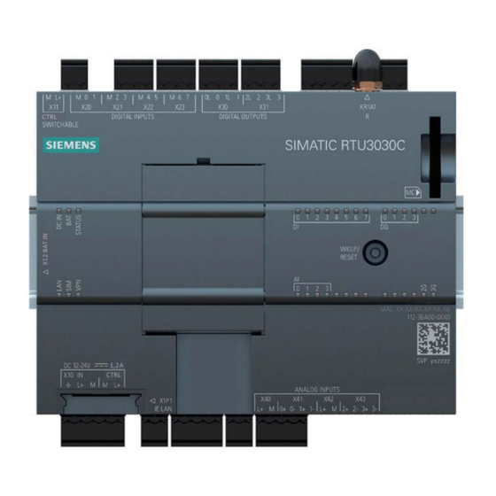
LEDs, connectors, buttons, card slots Appearance of the device Figure 2-1 Location of the LEDs, connectors, buttons, card slots Table 2- 1 Meaning of the number symbols ① ⑪ X11: Control output to supply sensors and actuators MAC address ② ⑫... -
Page 46: Leds
LEDs, connectors, buttons, card slots 2.2 LEDs ⑨ AI: Status LEDs for analog inputs ⑲ X12 BAT IN: Connector for battery module (on the side) DQ: Status LEDs for digital outputs (RTU3031C) ⑩ ⑳ Wireless status LEDs RTU status LEDs "DC IN", "BAT", "STATUS" LEDs LEDs of the device To reduce current consumption, the LEDs are turned off during operation of the RTU. - Page 47 LEDs, connectors, buttons, card slots 2.2 LEDs Information on the tables LED symbols The LED symbols in the following tables have the following significance: Table 2- 3 Meaning of the LED symbols Symbol LED status ON (steady light) Flashing "Meaning" column If a cell in the "Meaning"...
- Page 48 LEDs, connectors, buttons, card slots 2.2 LEDs RTU status LEDs Table 2- 4 RTU status LEDs Name Color Meaning DC IN External power OFF External voltage ON, voltage value in the range 10.8 ... 28.8 V, but not configured External voltage ON, voltage value in the range 10.8 ... 28.8 V No power supply from battery modules •...
- Page 49 LEDs, connectors, buttons, card slots 2.2 LEDs Name Color Meaning No configuration • Duplicate IP address • flashing red No IP lease received from DHCP server (when the IP • address is obtained automatically) Overload at one of the voltage outputs: •...
- Page 50 LEDs, connectors, buttons, card slots 2.2 LEDs Name Color Meaning Data transfer with good wireless link quality (> -79 dBm) RTU3031C: GPS No update mode • No reception • GPS disabled in the configuration • Position determination active Receiving position Status LEDs of the inputs (DI, AI) and outputs (DQ) Table 2- 7 IO status LEDs...
-
Page 51: Interfaces And Connectors
LEDs, connectors, buttons, card slots 2.3 Interfaces and connectors Name Color Meaning Outside of the update cycle • Connected device does not send data • RTU receives data from the bus RS485 Extension board not configured • Modbus RTU not enabled •... - Page 52 LEDs, connectors, buttons, card slots 2.3 Interfaces and connectors You configure the power supply of the RTU itself and the control outputs of the RTU in the WBM, refer to the section Power supply (Page 171). Note Output voltage The voltage at the terminals X10, X11, X40 and X42 of the RTU and CTRL at the extension board can be set to 12 or 24 V DC in the WBM for all control outputs.
- Page 53 LEDs, connectors, buttons, card slots 2.3 Interfaces and connectors NOTICE Suitable fuse for the power supply cables (corresponds to "Limited Energy") The current on the terminal may not exceed 3 A. Use a fuse for the power supply that is suitable for protection of AC/DC power supply circuits * and protects against currents >...
- Page 54 LEDs, connectors, buttons, card slots 2.3 Interfaces and connectors X10 CTRL is regulated; in other words the voltage is independent of X10 IN. Voltage fluctuations of the external power supply are not passed on to X10 CTRL. X10 is not designed for the power supply of powerful actuators. Remember the maximum permitted power in the section Technical data (Page 335).
- Page 55 LEDs, connectors, buttons, card slots 2.3 Interfaces and connectors When necessary, actuators can be supplied with voltage via the control outputs X10 or X11 of the RTU. The digital outputs are designed as bistable relays which maintain their current state even in sleep mode of the RTU without power supply.
- Page 56 LEDs, connectors, buttons, card slots 2.3 Interfaces and connectors X1P1: Ethernet interface X1P1 is the LAN connector of the RTU. Note No connection to the Internet The LAN connector is not suitable for direct connection of the RTU to the Internet. To do this, an external router with suitable security mechanisms must be connected.
-
Page 57: The Button "Wkup/Reset
LEDs, connectors, buttons, card slots 2.4 The button "WKUP/RESET" The button "WKUP/RESET" Functions of the button The "WKUP/RESET" button has the following functions: ● Set the RTU to the service mode Setting the RTU to the service mode activates the LEDs and the LAN interface "X1P1". For a period that can be configured in the WBM, the connection of a configuration computer to the LAN interface and the call of the WBM are therefore enabled. -
Page 58: Slots For Sim Card And Sd Card
LEDs, connectors, buttons, card slots 2.5 Slots for SIM card and SD card Slots for SIM card and SD card " SIM": Slot for the SIM card On the underside of the RTU there is a slot marked " SIM" for the SIM card you obtain from the network provider of your mobile wireless contract Compatible cards The card slot and the RTU are compatible with the following card formats:... - Page 59 LEDs, connectors, buttons, card slots 2.5 Slots for SIM card and SD card Retentive storage of important data on the SD card The SD card is an exchangeable storage medium for storing various data safe from power failure. Note Operation with SD card It is strongly recommended that you only operate the RTU with an SD card, in particular because an SD card is required in the following situations: •...
- Page 60 LEDs, connectors, buttons, card slots 2.5 Slots for SIM card and SD card RTU303xC Operating Instructions, 06/2019, C79000-G8976-C382-06...
-
Page 61: Connecting Up, Installation, Commissioning
Connecting up, installation, commissioning Important notes on using the device Safety notices on the use of the device Note the following safety notices when setting up and operating the device and during all associated work such as installation, connecting up or replacing the device. WARNING Safety requirements for installation The devices are "open equipment"... - Page 62 Connecting up, installation, commissioning 3.1 Important notes on using the device WARNING EXPLOSION HAZARD Do not press the button "WKUP RESET" if there is a potentially explosive atmosphere. WARNING EXPLOSION HAZARD DO NOT CONNECT OR DISCONNECT EQUIPMENT WHEN A FLAMMABLE OR COMBUSTIBLE ATMOSPHERE IS PRESENT.
-
Page 63: Notices On Use In Hazardous Areas According To Atex / Iecex
Connecting up, installation, commissioning 3.1 Important notes on using the device WARNING EXPLOSION HAZARD The equipment is intended to be installed within an enclosure/control cabinet. The inner service temperature of the enclosure/control cabinet corresponds to the ambient temperature of the module. Use cables with a maximum permitted operating temperature of at least 20 °C higher than the maximum ambient temperature. -
Page 64: Instructions For Use In Hazardous Areas According To Fm And Ul Hazloc
3.1 Important notes on using the device WARNING DIN rail In the ATEX and IECEx area of application only the Siemens DIN rail 6ES5 710-8MA11 may be used to mount the RTU and the battery modules. 3.1.3 Instructions for use in hazardous areas according to FM and UL HazLoc... -
Page 65: Safety When Connecting (Devices Without Nec Class 2)
Connecting up, installation, commissioning 3.1 Important notes on using the device WARNING Wall mounting is only permitted if the requirements for the housing, the installation regulations, the clearance and separating regulations for the control cabinets or housings are adhered to. The control cabinet cover or housing must be secured so that it can only be opened with a tool. - Page 66 Connecting up, installation, commissioning 3.1 Important notes on using the device NOTICE Suitable fuse for the power supply cables (corresponds to "Limited Energy") The current on the terminal may not exceed 3 A. Use a fuse for the power supply that is suitable for protection of AC/DC power supply circuits * and protects against currents >...
-
Page 67: Device Defective
3.2 Requirements for commissioning 3.1.5 Device defective Device defective If a fault develops, please send the device to your SIEMENS service center for repair. Repairs on-site are not possible. Requirements for commissioning Prior to commissioning The following requirements must be met before you commission the RTU: ●... -
Page 68: Sd Card / Using And Formatting Smc
● Use of an SMC An SMC must not be formatted like a standard SD card otherwise it cannot be used. You will find instructions on repairing and formatting on the pages of the Siemens Industry Online Support in the following FAQ: Link: (http://support.automation.siemens.com/WW/view/en/69063974) -
Page 69: Inserting The Sim Card And Sd Card
Connecting up, installation, commissioning 3.4 Inserting the SIM card and SD card Inserting the SIM card and SD card Inserting the SIM card Recommendation: Insert the SIM card in the RTU before you install it. After installing and connecting up the answer you, the space for inserting the SIM card may be very restricted. Before inserting or changing the SIM card make sure that the power supply is turned off. -
Page 70: Installing An Rtu
Connecting up, installation, commissioning 3.5 Installing an RTU Insert the card in the slot "MC " until it locks gently in place. Make sure that the card is in the correct position. Removing the SD card Note Pulling the SIM card Do not remove the SD card while the device is operating. - Page 71 If you do not mount the RTU or the battery module in a protective housing from the accessories program, prevent the battery module from slipping with a suitable clamping device, e.g. a Siemens end retainer 8WA1808. When using the device in the areas of application ATEX or IECEx, note the information on the DIN rail being used in section Notices on use in hazardous areas according to ATEX / IECEx (Page 63).
- Page 72 Connecting up, installation, commissioning 3.5 Installing an RTU Table 3- 1 Procedure for installation Step Execution Notes and explanations Remove the covers on the left-hand side of the Recommendation: Store the covers RTU. in a safe place in case they need to be used later.
-
Page 73: Grounding And Overvoltage Protection
Connecting up, installation, commissioning 3.6 Grounding and overvoltage protection Table 3- 2 Procedure for installation Step Execution Notes and explanations When using the extension board, remove the co- Recommendation: Store the cover in vers: a safe place in case it needs to be used later. -
Page 74: Connecting Up The Rtu
Connecting up, installation, commissioning 3.7 Connecting up the RTU Cables at risk The RTU is at risk via the following cables: ● The supply cables of the optional external power supply of the RTU. ● All signal cables and cables to the power supply of sensors, switches and other devices connected to the RTU. - Page 75 Connecting up, installation, commissioning 3.7 Connecting up the RTU Protect the antenna connector with a suitable overvoltage protection module if you install the antenna outdoors. See section Grounding and overvoltage protection (Page 73) for information on this. An antenna is not included in the scope of delivery. You will find the compatible antenna in the appendix Antennas and accessories (Page 363).
- Page 76 Connecting up, installation, commissioning 3.7 Connecting up the RTU You can connect two actuators to each of the two terminal blocks of the digital outputs. In total, up to 4 actuators can be connected. Assignment of the contacts based on the example of terminal block X30 for digital outputs 0 and 1: ●...
- Page 77 Connecting up, installation, commissioning 3.7 Connecting up the RTU Figure 3-3 Wiring of digital outputs X32 to X33 For the power supply of the connected actuators, you can use the control outputs X10 or X11 of the RTU. Connecting up the analog inputs X40 to X43 You can connect up to 4 analog measuring transducers to the RTU.
- Page 78 Connecting up, installation, commissioning 3.7 Connecting up the RTU Connecting a 2-wire measuring transducer Figure 3-5 Connecting a 2-wire measuring transducer Terminal "M" of the terminal block X40 and terminal "0-" of terminal block X41 need to be bridged. Connecting a 3-wire measuring transducer Figure 3-6 Connecting a 3-wire measuring transducer The terminal "M"...
- Page 79 Connecting up, installation, commissioning 3.7 Connecting up the RTU Connecting a 4-wire measuring transducer Figure 3-8 Connecting a 4-wire measuring transducer Connecting a 4-wire measuring transducer with external power supply Figure 3-9 Connecting a 4-wire measuring transducer with external power supply Connecting a temperature sensor Figure 3-10 Connecting a temperature sensor...
-
Page 80: Connecting Devices To The Extension Board
Connecting up, installation, commissioning 3.8 Connecting devices to the extension board This connector is not suitable for the power supply of powerful actuators. Note the maximum power consumption in the section Technical data (Page 335). You specify the voltage value (12 or 24 V) in the WBM ("Operating mode" > "Power supply"). Connecting the 12/24 V control output X10 CTRL to sensors and switches To supply sensors, actuators and switches of actuators connected to the RTU, you can connect these to the control output X10 CTRL. -
Page 81: Hart Devices
Connecting up, installation, commissioning 3.8 Connecting devices to the extension board also need to be attached in order to guarantee a minimum differential voltage of 200 mV with a high-resistance bus. The fail-safe resistors are usually attached at the bus master. The HART/RS-485 extension board features fail-safe resistors that can be connected internally. - Page 82 Connecting up, installation, commissioning 3.8 Connecting devices to the extension board The extension board has two terminals "HART-OUT" and "HART-R" as well as the terminals "L+" (12/24 V DC) and "M" for connecting HART Multidrop devices. Passive sensors can be supplied via the 12/24 V DC terminal of the module.
- Page 83 Connecting up, installation, commissioning 3.8 Connecting devices to the extension board Figure 3-15 Connection of passive sensors with power supply via expansion card and external resistor Figure 3-16 Mixed operation of active and passive sensors with internal resistor Figure 3-17 Mixed operation of active and passive sensors with external resistor RTU303xC Operating Instructions, 06/2019, C79000-G8976-C382-06...
-
Page 84: Commissioning And Starting Up The Rtu
Connecting up, installation, commissioning 3.9 Commissioning and starting up the RTU Commissioning and starting up the RTU Note Startup with an SD card that is not brand new If the RTU starts up with an SD card that is not brand new, observe the behavior of the RTU in terms of the configuration file used, refer to the section Configuration (Page 122). - Page 85 Connecting up, installation, commissioning 3.9 Commissioning and starting up the RTU Depending on the type of power supply, follow the steps below: Supply of the RTU only via external power supply Turn on the external power supply. The RTU starts up. Supply of the RTU only via battery modules NOTICE Do not place the battery holders on a conductive surface.
- Page 86 Connecting up, installation, commissioning 3.9 Commissioning and starting up the RTU Figure 3-18 Battery module (not mounted) with inserted battery holder, cable connected. Note Starting battery operation The RTU only starts up when there are two batteries with adequate voltage and capacity in the main battery module.
- Page 87 Connecting up, installation, commissioning 3.9 Commissioning and starting up the RTU ● The RTU changes to update mode: – All connected and configured inputs are read. – The read data is processed if programmed. – The data is saved. – The outputs are updated if programmed. ●...
- Page 88 Connecting up, installation, commissioning 3.9 Commissioning and starting up the RTU RTU303xC Operating Instructions, 06/2019, C79000-G8976-C382-06...
-
Page 89: Configuration (Wbm)
● Keep the firmware up to date. Check regularly for security updates of the firmware and use them. ● Check regularly for new features on the Siemens Internet pages. – Here you will find information on industrial security: Link: (http://www.siemens.com/industrialsecurity) –... - Page 90 Configuration (WBM) 4.1 Security recommendations Passwords ● Define rules for the use of devices and assignment of passwords. ● Regularly update the passwords to increase security. ● Only use passwords with a high password strength. Avoid weak passwords for example "password1", "123456789"...
- Page 91 Configuration (WBM) 4.1 Security recommendations Table 4- 1 Server ports of the LAN interface Protocol / function Port number (pro- Default of the port Port status Authentication tocol) HTTP 80 (TCP) Open Open after configuration HTTPS 443 (TCP) Open Open 53 (UDP) Open Open...
-
Page 92: Range Of Functions Of The Wbm
Configuration (WBM) 4.2 Range of functions of the WBM These can be: ● TeleControl Basic / 55097 * (TCP) ● ST7 / 26382 * (TCP) ● FTP / 21 * (TCP) (and dynamically decided by the server, passive mode) ● DHCP / 67, 68 (UDP) (only LAN) ●... - Page 93 Configuration (WBM) 4.2 Range of functions of the WBM ● Communications functions of the RTU ● Logging of system events Programming the program blocks for the controller In the WBM, you program the program blocks for the control tasks of the RTU using a graphic user interface.
-
Page 94: General Functions Of The Wbm
Updates the current display on WBM pages on which entries can be made. During the update a progress bar is visible. Opens the Internet page of the RTU in the Siemens Industry Online Portal. Here, you will find all entries for the product. -
Page 95: Permitted Characters And Parameter Lengths
Configuration (WBM) 4.4 Permitted characters and parameter lengths Grayed out boxes are preset by the system and cannot be changed. Note Data loss when changing the WBM page without saving If you do not save your input with the "Apply" button, your input will be discarded without a prompt for confirmation when you change WBM pages. - Page 96 Configuration (WBM) 4.4 Permitted characters and parameter lengths Special characters ● 0x20 Space ● 0x21 .. 0x2F ! " # $ % & ' ( ) * + , - . / ● 0x3A .. 0x40 : ; < = > ? @ ●...
- Page 97 Configuration (WBM) 4.4 Permitted characters and parameter lengths Parameter String length Permitted characters / format Min. Max. 0x30 .. 0x39 Standard characters and period (DNS name according to RFC 1035 and RFC 1123): 0x2E • 0x30 .. 0x39 • 0x41 .. 0x5A •...
- Page 98 Configuration (WBM) 4.4 Permitted characters and parameter lengths Parameter String length Permitted characters / format Min. Max. E-mail address The e-mail address has the following structure: Part1@Part2.Part3 Part 1@: Standard characters + special characters (< 0x80; only one "@" character is allowed) Part 2+3: Standard characters Tags and program blocks Data point name...
- Page 99 Configuration (WBM) 4.4 Permitted characters and parameter lengths Parameter String length Permitted characters / format Min. Max. Messages Message texts including up 0x30 .. 0x39 • to 6 placeholders for process 0x41 .. 0x5A • values with formatting in- 0x61 .. 0x7A •...
-
Page 100: Permissible File Size For Certificates And Keys
Configuration (WBM) 4.5 Permissible file size for certificates and keys Parameter String length Permitted characters / format Min. Max. SINEMA RC Password All the characters listed above Tag tables Table names All the characters listed above Texts in the tag tables All the characters listed above Permissible file size for certificates and keys When configuring certificate-based services, only certificate and key files with the following... -
Page 101: Establishing A Connection To The Wbm Of The Rtu
Configuration (WBM) 4.6 Establishing the connection between RTU and configuration PC 4.6.2 Establishing a connection to the WBM of the RTU Using the HTTP/HTTPS protocol The HTTPS protocol is always activated. HTTP can be disabled in the configuration. You can establish a connection between the configuration PC and RTU using the HTTP or HTTPS protocol: ●... - Page 102 Configuration (WBM) 4.6 Establishing the connection between RTU and configuration PC OpenVPN for HTTP connections from the configuration PC to the RTU via WAN If you want to establish an HTTP connection to the WBM of the RTU from your configuration PC via mobile wireless, you need to use OpenVPN.
- Page 103 Configuration (WBM) 4.6 Establishing the connection between RTU and configuration PC Figure 4-2 Connection between the configuration PC and RTU via WAN using OpenVPN Preparing the PC interface Follow the steps below to prepare the interface of the configuration PC for the connection to the RTU.
- Page 104 Configuration (WBM) 4.6 Establishing the connection between RTU and configuration PC 6. Click "Properties". In the properties dialog that opens, the settings depend on whether you have activated the DHCP server function of the RTU, refer to section LAN (Page 130). Make the settings according to the DHCP configuration, refer to the following sections.
- Page 105 Configuration (WBM) 4.6 Establishing the connection between RTU and configuration PC DHCP server of the RTU disabled Requirements: On the RTU the "Specify IP address manually" option was enabled earlier. There is no DHCP server in the local network. 1. Select the option to assign an IP address. 2.
-
Page 106: User Data For The First Login To The Wbm
Configuration (WBM) 4.7 User data for the first login to the WBM User data for the first login to the WBM Standard user data In the factory the following login data is set as default. Note With the following user data you can log in the first time to the WBM. User data Default values set in the factory User name... -
Page 107: Logging In
Configuration (WBM) 4.8 Logging in Logging in Logging in After establishing a connection between the configuration PC and the RTU, the WBM opens with the page for the user to log in. Enter the user name and the password. Note User data When you log in the first time note to the information in the section User data for the first login to the WBM (Page 106). -
Page 108: Start Page
Configuration (WBM) 4.9 Start page Start page 4.9.1 Overview Overview After logging in to the WBM, the start page appears. In the title bar of the Browser tab, the station name of the RTU is displayed that you configure in "System". In the title bar of the window apart from the user name (left) and the general buttons for the WBM (right) you will find the following information: ●... - Page 109 Configuration (WBM) 4.9 Start page The "Overview" tab The "Overview" tab shows a picture of the RTU. When you are connected to the operating RTU, the LED symbols shown in the WBM reflect the original status of the LEDs on the RTU. If the extension board is activated, it is also displayed.
-
Page 110: Status
Configuration (WBM) 4.9 Start page Navigation in the WBM By clicking on an entry in the navigation area on the left open the WBM page you want for further information or on which you want to configure or program. The WBM opens the first tab of the entry. 4.9.2 Status The tab provides an overview of important status data of the RTU. - Page 111 Configuration (WBM) 4.9 Start page Mobile wireless interface Information on the configuration data and the current status of the mobile wireless interface ● Connected since (dd:hh:mm:ss) Time since last booking into the mobile wireless network. ● Data connection since (dd:hh:mm:ss) The time since the connection to the data service of the mobile wireless network.
-
Page 112: System
Configuration (WBM) 4.10 System 4.10 System 4.10.1 General Note the characters permitted for the input boxes, see section Permitted characters and parameter lengths (Page 95). ● Station name Assign the station name of the RTU. The station name of the RTU provides structural information within you system. Note Host name (DNS) The station name is used as the RTU host name for DNS servers. -
Page 113: Device Info
Configuration (WBM) 4.10 System Location Enter the latitude and longitude of the RTU location as degrees. The entry is made in decimal degrees. ● Latitude Value range: -90.000000 .. 90.000000 Positive values for north, negative values for south ● Longitude Value range: -180.000000 .. - Page 114 Configuration (WBM) 4.10 System Notifications ● Notifications Here you specify whether the events that can be configured later cause a message (SMS message or e-mail) to be sent or not. ● Change immediately to communication mode If the option is enabled if one of the events configured later occurs, the RTU changes to communication mode and sends the message.
- Page 115 Configuration (WBM) 4.10 System Savable files below the parameter area Below the parameter area, the names of the files saved on the SD card are displayed. By clicking on the file name, you can save the file from the SD card to the file system of your Naming conventions for the file names Files that were written to the SD card from the RTU, meet the DOS format: <1...8 characters>.<1...3 characters>...
-
Page 116: System Time
Configuration (WBM) 4.10 System ● Diagnostics buffer file File with the diagnostics buffer entries of the RTU: diagbuf.txt ● Other files Files that you yourself save on the SD card:. 4.10.4 System time Buffering of the time The internal RTU clock is maintenance free and buffered by a capacitor, to be able to bridge the duration of a battery change. - Page 117 Configuration (WBM) 4.10 System Local time zone ● Time Zone Set the time zone in which the RTU is located either by entering it manually or selecting an entry from the drop-down list. ● Automatic daylight saving time switch If you sent the time zone manually, you can enable the automatic changeover of daylight saving time and standard time and set the parameters for this.
- Page 118 Configuration (WBM) 4.10 System NTP settings ● Interface Select the interface via which the RTU will be synchronized. ● IP address or DNS name of the NTP server Assign the address of the NTP server. ● Accept time of day from non-synchronized NTP servers If the option is enabled, the RTU also accepts the time-of-day from non-synchronized NTP servers with stratum ≥...
- Page 119 Configuration (WBM) 4.10 System The system time set here is kept by the internal clock of the RTU. For information on the accuracy, see section Technical data (Page 335). ● New system time Here, enter the current time of day manually. When making your entry, keep to the specified format.
-
Page 120: Diagnostics
Configuration (WBM) 4.11 Diagnostics 4.11 Diagnostics 4.11.1 Diagnostics buffer Diagnostics buffer The diagnostics buffer receives diagnostics messages for internal events and errors. It can hold a maximum of 200 entries. When the maximum number is exceeded, the oldest entries are overwritten. The entries in the diagnostics buffer contain a consecutive number, a classification, a time stamp in local time and the message text. -
Page 121: Configuration
Configuration (WBM) 4.11 Diagnostics Error identifiers for the transfer of e-mails and FTP files You will find possible error identifiers for transfer errors that can be included in the diagnostics buffer entries in the section Error detections for Telecontrol, e-mails and FTP (Page 327). -
Page 122: Maintenance
Configuration (WBM) 4.12 Maintenance 4.12 Maintenance 4.12.1 Configuration In this tab you can save the configuration data of the RTU in a configuration file and load it again. Configuration files have the file format *.cfg Note RTU3010C, RTU3030C and RTU3031C incompatible Note that configurations of RTU3010C, RTU3030C and RTU3031C are not compatible. - Page 123 Configuration (WBM) 4.12 Maintenance Save configuration With this function the current configuration data of the RTU is saved in a configuration file. ● Save on SD card Saves the current configuration file under the name "user.cfg" on the SD card. ●...
-
Page 124: Firmware
Digitally signed and encrypted firmware prevents manipulation by third parties To be able to check the authenticity of the firmware, the firmware is digitally signed by Siemens. This allows manipulation by third parties to be detected and prevented. The encryption of the firmware is intended to prevent re-engineering. - Page 125 The version of the mobile wireless module of the RTU Firmware update If a new firmware version is available for the RTU, you will find this on the Internet pages of Siemens Industry Online Support: Link: (https://support.industry.siemens.com/cs/ww/en/ps/15920) Firmware files have the file format *.sfw Download the firmware file to the file system of your configuration PC.
- Page 126 Configuration (WBM) 4.12 Maintenance If If you do not want to use the loaded firmware file, you can remove this again with the "Delete" button. ● Activate and restart If you want to use the downloaded firmware file, click the "Activate and restart" button. Note that updating the firmware can take a while.
-
Page 127: Operating Status
Configuration (WBM) 4.12 Maintenance 4.12.3 Operating status Operating statuses Apart from using this WBM page you can also execute the functions described below using the button on the RTU, see section The button "WKUP/RESET" (Page 57). The three buttons on this tab have the following functions: ●... - Page 128 Configuration (WBM) 4.12 Maintenance Note RTU not reachable via the mobile wireless network After resetting to factory settings, the RTU can no longer be reached via the mobile wireless network. If an SD card is plugged in, the following are also deleted: ●...
-
Page 129: Online Support
Online support Link to the Internet portal of Siemens Industry Online Support Click on "Siemens Industry Online Support" to connect to the Internet pages of Siemens Online Support. There, you can search for information on the product or send a query to product support. -
Page 130: Lan
The data is saved on the SD card in a log file with the name "support.bin". The information in this file is encrypted and can only be read by Siemens Industry Online Support. On completion of logging sent the log file back to your contact at Siemens Industry Online Support. -
Page 131: Configuration
Configuration (WBM) 4.13 LAN ● Default router Shows the configured IP address of the router being used or the one last obtained with DHCP. ● DNS server Shows the configured IP addresses of the DNS servers in the network or last obtained with DHCP (max. - Page 132 Configuration (WBM) 4.13 LAN IP parameter Note DHCP client function The DHCP client function of the RTU is activated when the following conditions are met: • The "Specify IP address manually" option is disabled. In this case, the DHCP server of the RTU cannot be activated. The IP address of the RTU and optionally of the router and the addresses of up to two DNS servers are obtained from a DHCP server in the network.
-
Page 133: Wan
Configuration (WBM) 4.14 WAN ● Specify default router manually If you use a router, activate the option. – Default router Enter the router IP address. An address obtained from a DHCP server is overwritten. ● DHCP server active If the option is active the RTU assigns the IP address and the DND server to the configuration PC to be connected. - Page 134 Configuration (WBM) 4.14 WAN Mobile wireless connection ● Status of the SIM card – Check mark on a green background Indicates that the entered PIN is identical with the PN on the SIM card. The PIN was saved successfully on the device. –...
-
Page 135: Mobile Wireless Settings
Configuration (WBM) 4.14 WAN Statistics ● SMS sent Number of SMS messages that the RTU has sent. ● SMS in send queue Number of SMS messages ready to be sent, but that have not yet been sent. ● Sending the SMS failed Number of SMS messages that were ready to be sent on the RTU that could, however, not be sent due to disruptions. - Page 136 Configuration (WBM) 4.14 WAN Mobile wireless settings Here you configure the mobile wireless connection of the RTU. ● Enable mobile wireless interface Activates the mobile wireless interface of the RTU. If the mobile wireless interface is deactivated, the RTU can no longer be reached using mobile wireless.
- Page 137 Configuration (WBM) 4.14 WAN ● PLMN This is where you enter the PLMN (Public Land Mobile Network) of the desired network provider. You can obtain PLMN from your network provider or find it on the Internet. PLMN is a worldwide unique identifier of mobile wireless networks consisting of: –...
- Page 138 Configuration (WBM) 4.14 WAN ● User name Enter the user name for the APN. You obtain access data from your mobile wireless network provider. If your mobile wireless network provider does not require access data, leave the boxes for user name and password empty. ●...
- Page 139 Configuration (WBM) 4.14 WAN Logging Options for Signal strength and Cell ID detection as well for sent and received data: ● OFF: The process data is never saved to the SD card. ● Always: The process data is saved with each update cycle ●...
-
Page 140: Wireless Cell
Configuration (WBM) 4.14 WAN 4.14.3 Wireless cell Note Updating the data The data on this page is updated at 1 second intervals. Calling up this page means that the RTU uses more energy. ● Wireless cell identifier (CI) ● Signal strength CSQ (dbm) Signal strength of the mobile wireless network as CSQ (Cell Signal Quality) and as received signal strength RSSI [dBm] CSQ and RSSI correspond as follows:... -
Page 141: Sms
Configuration (WBM) 4.14 WAN 4.14.4 In this tab you can allow or block receipt of SMS messages by the RTU. ● Allow receipt of SMS messages If the option is enabled, the RTU can receive SMS messages. To allow further evaluation the received messages must correspond to the codings GSM 3.38 or UCS. -
Page 142: Dyndns
Configuration (WBM) 4.14 WAN Test SMS Here, for example, you can send a test SMS message during commissioning. ● Recipient group Here, enter the recipient group for the message. You configure recipient groups on the WBM page "Recipient / Groups". ●... - Page 143 Configuration (WBM) 4.14 WAN The reachability of the IP address from the Internet must be enabled by the service provider. ● Active – If the option is enabled, the use of DynDNS is enabled. – If the option is disabled, the use of DynDNS is not enabled. ●...
-
Page 144: Services
Configuration (WBM) 4.15 Services ● Load new file After selecting a file stored on the configuration PC using the "Search" button, the file name is displayed here. ● Search Searches the file system of the configuration PC for a certificate file saved there that is intended to be loaded on the RTU. -
Page 145: E-Mail
Configuration (WBM) 4.15 Services 4.15.2 E-mail In this tab you make these settings for sending e-mails. You will find the various types of e- mail in the section Communications services (Page 25). The following data must be configured: ● Active If the option is activated, the RTU can send e-mails. - Page 146 Configuration (WBM) 4.15 Services CA certificate Here, you have the option of configuring the CA certificate or intermediate certificate of the mail server or the individual server certificate for sending e-mail with STARTTLS. ● Currently used file Shows the name of the certificate file currently being used by the RTU.. ●...
- Page 147 Configuration (WBM) 4.15 Services ● Password Password for the encryption of the e-mail attachments. The attachments can only be decrypted with this password. ● Additional communication cycle at a number of buffered e-mails Here, you can enter the number of stored e-mails as of which the RTU runs through an additional communication cycle.
-
Page 148: Ftp
Configuration (WBM) 4.15 Services 4.15.3 In this tab you make the settings for the transfer (PUT function) of files to an FTP server. The function is made possible by the program block "FTP file transfer". In "Operating mode > Logging" you can still configure the transfer of the previous log file when a new log file is created. - Page 149 Configuration (WBM) 4.15 Services CA certificate Here, you have the option of configuring the CA certificate or intermediate certificate of the FTP server or the individual server certificate of the FTP server. ● Currently used file Shows the name of the certificate file currently being used by the RTU.. ●...
-
Page 150: Security
Configuration (WBM) 4.16 Security Paths of the FTP server If you do not want to save the files in the standard directory of the server, you can specify optional paths here. The configured paths must correspond to the path names on the server. If the paths do not exist, they are created by most servers when the first transfer is made. -
Page 151: Vpn
● Security functions for communication (Page 32) For VPN tunnels the following alternatives can be configured: ● SINEMA Remote Connect SINEMA RC is the recommended Siemens application for OpenVPN tunnels. ● OpenVPN With this option configure a freely selectable OpenVPN server. - Page 152 Configuration (WBM) 4.16 Security ● Currently used port number Currently used port number of the SINEMA RC server. ● Interface Interface for communication: – LAN – WAN ● Device ID Device ID that was assigned to the RTU in the SINEMA RC Server configuration. ●...
- Page 153 Configuration (WBM) 4.16 Security ● Verification of the server certificate necessary The function is optional but for security reasons is, however, recommended. If this option is enabled during connection establishment, the client checks whether the certificate of the server is actually a server certificate based on the purpose of the certificate.
- Page 154 Configuration (WBM) 4.16 Security ● Renewal interval for session key (s) Interval (seconds) at which the session key is exchanged with the server. Permitted range: 0 to 65535 s. Default: 3600 s. If you enter 0 (zero), the function is deactivated.
- Page 155 Configuration (WBM) 4.16 Security ● Search Searches the file system of the configuration PC for a certificate file saved there that is intended to be loaded on the RTU. ● Load on device By clicking the button, you download the selected file to the RTU. Own certificate Here, you import the client certificate for the RTU.
-
Page 156: Https
Configuration (WBM) 4.16 Security Load PEM file If you want to load the two certificates and the key from the OpenVPN server as a common PEM file, then enable this option. ● Password Enter the password specified with the OpenVPN server if you exported the key password- protected. - Page 157 Configuration (WBM) 4.16 Security HTTPS The following settings apply for access via LAN and via mobile wireless. ● Allow only HTTPS access If the option is activated, connections can only be established to the WBM of the RTU with HTTPS. Non secure connections with HTTP are not permitted If you connect to the RTU via an HTTP connection, activate and save this option, the existing HTTP connection between the PC and RTU can no longer be used.
- Page 158 Configuration (WBM) 4.16 Security Alternatively, you can import a third-party certificate. For example, it can be a certificate signed by a public certification authority and issued to the host name you have entered under DynDNS and under the RTU which you can reach on the Internet. ●...
-
Page 159: Event Buffer
Configuration (WBM) 4.16 Security ● Search Searches the file system of the configuration PC for a key file saved there that is intended to be loaded on the RTU. ● Load on device With the button "Load on device" load the selected file on the RTU. 4.16.4 Event buffer Event buffer... -
Page 160: Syslog
Configuration (WBM) 4.16 Security 4.16.5 Syslog Syslog Syslog according to RFC 5424 is used for transferring short, unencrypted text messages over UDP in the IP network. A Syslog server or a SIEM system are required for this. ● Active When enabled, the device sends security events to a Syslog server. ●... -
Page 161: Users / Groups
Configuration (WBM) 4.17 Users / groups 4.17 Users / groups 4.17.1 User Incorrect entry / loss of the user name or passwords Note With the following user data you can log in the first time to the WBM. User data Default values set in the factory User name admin... - Page 162 Configuration (WBM) 4.17 Users / groups Table The table shows all users and their configured data. ● Add Creates a new user. When you create a new user, you need to assign the name, the user name and the password. . You can leave the other data boxes empty and complete them later. ●...
- Page 163 Configuration (WBM) 4.17 Users / groups ● Phone number The phone number of the user configured here is the authorized telephone number for waking the RTU and for receiving SMS messages by the RTU. For these functions the user requires a phone with the number entered here. The telephone must support the CLIP function (transfer of its own call number).
-
Page 164: Recipient Groups
Configuration (WBM) 4.17 Users / groups To change the access data (user name, password), you need to select the "Change login data" check box. The input boxes can then be edited. ● Change login data When this option is enabled, you can change user data. ●... - Page 165 Configuration (WBM) 4.17 Users / groups Table The table shows all recipient groups and their configured data. ● Add Creates a new group. When creating a new group, you need to assign the name and select the group type. You can leave the description empty and complete it later.
-
Page 166: Operating Mode
Configuration (WBM) 4.18 Operating mode 4.18 Operating mode 4.18.1 Operating modes You will find the description of the Operating modesin the section Modes and operating modes (Page 21). Note Power consumption Note that frequent update and communication cycles increase the power consumption of the RTU greatly. - Page 167 Configuration (WBM) 4.18 Operating mode The time-of-day synchronization is performed with the communication cycle. ● Always remain connected If you enable this option, the RTU remains permanently in the communication mode and connected to the communications partner. ● Basic cycle From the drop-down list, specify the basic cycle (3 minutes ...
- Page 168 Configuration (WBM) 4.18 Operating mode Sleep mode ● Turn on mobile wireless interface regularly and check for receipt of wake-up SMS message? Using the drop-down list, you specify whether the RTU dials into the mobile wireless network in addition to the communication cycle to fetch any existing SMS messages. The following options are available: –...
-
Page 169: Logging
Configuration (WBM) 4.18 Operating mode 4.18.2 Logging You will find the naming conventions of the log files in the section SD card (Page 113). ● Active Selecting the check box turns on logging. A further requirement is a plugged in SD card. ●... - Page 170 Configuration (WBM) 4.18 Operating mode ● Send last log file by e-mail when a new one is created. If the option is enabled, the last log file is sent as an attachment of an e-mail as soon as a new log file is created. –...
-
Page 171: Power Supply
Configuration (WBM) 4.18 Operating mode 4.18.3 Power supply Power supply Here you configure the various options for the power supply of the RTU, changing battery modules, the power outputs of the RTU and possibly notifications. Designation of the battery modules ●... - Page 172 Configuration (WBM) 4.18 Operating mode ● Connect battery By clicking the button, you connect the plugged in battery module and its expansion modules logically with the RTU. Without the connection on this WBM page, the RTU does not access the physically plugged in battery module.
- Page 173 Configuration (WBM) 4.18 Operating mode Control outputs ● Output voltage (X10 CTRL, X11, X40, X42) From the drop-down list select the voltage (12 VDC or 24 VDC) at the voltage outputs of the RTU. Outputs X40 and X42 are supplied with the voltage configured here in the update cycle if the associated analog inputs are configured with power supply "On".
- Page 174 Configuration (WBM) 4.18 Operating mode ● After battery operating time of: If the option is enabled, a message is sent when the configured value of the operating time of the active battery module is reached after being activated by the RTU. ●...
- Page 175 Configuration (WBM) 4.18 Operating mode To change the batteries, you first need to disconnect the battery module being used in the configuration. Follow these steps: 1. In the WBM, open the page. "Power supply". 2. Disconnect the battery module currently being used in the parameter group. "Battery module 1"...
-
Page 176: Battery Service Life
Configuration (WBM) 4.18 Operating mode 4.18.4 Battery service life Remaining battery capacity In this tab (HW2), the calculated remaining capacity of the batteries, the consumption since the last activation and the theoretical remaining value are indicated. This calculation should help to better estimate electricity consumption. Exact calculation of the remaining capacity of the battery is not possible since this depends on numerous factors, for example, the connected consumers, changing outdoor temperatures and, above all, the frequency of configured events such as limits of measured... - Page 177 Configuration (WBM) 4.18 Operating mode The procedure in principle, is shown in the two following tables. Note Real values can significantly deviate from these. Note that the numbers shown as an example below can deviate significantly from the real behavior of the RTU in daily use. Calculate an adequate reserve.
-
Page 178: Tags
Configuration (WBM) 4.19 Tags 4.19 Tags 4.19.1 Overview Overview Table In the overview table all tags are shown as symbols with identifiers. By clicking on a symbol. You can directly to the WBM page for configuring this tag type. Symbols of unconfigured tags are gray, symbols of configured tags are green with different information. -
Page 179: Configuration Of The Tags , General Parameters
Configuration (WBM) 4.19 Tags Update cycle ● Basic cycle The basic update cycle is displayed at the top right on the WBM page. Copy of the process image ● Save to PC By clicking the button, you can save the current process image as a *.txt file on the configuration PC. - Page 180 Configuration (WBM) 4.19 Tags Enabling and names of the tags You need to configure the two following parameters for all tags except the tags for texts: ● Active If the option is enabled, the tag for productive operation is enabled. Unless it is enabled, the tag will not be processed in productive operation.
-
Page 181: Digital Inputs
Configuration (WBM) 4.19 Tags Format The parameters in the parameter group. "Format" are optional and can be left empty. Here, you specify texts for the individual tags, which are used when writing the process values to the SD card and for transferring process values in messages (SMS / e-mails). ●... - Page 182 Configuration (WBM) 4.19 Tags Digital input 2 to 7 for binary inputs If you use the two inputs for binary digital inputs, note that under certain circumstances this can lead to bouncing effects. For binary digital inputs you should preferably use digital inputs 2 to 7.
- Page 183 Configuration (WBM) 4.19 Tags ● Current sensor value Only with usage meters: Display of the value of the input ● Current process value Only with usage meters: Display of the physical value after converting the pulse weighting ● Read Click on the button to display the current value of the input. ●...
-
Page 184: Digital Outputs / Digital Memory Bits
Configuration (WBM) 4.19 Tags 4.19.4 Digital outputs / Digital memory bits Digital outputs / Digital memory bits Parameters ● Active ● Name ● Current value Display of the value of the output / memory bit ● Initial value Only with digital bit memory Preset value that the tag will use as the basic value. - Page 185 Configuration (WBM) 4.19 Tags Parameters ● Active ● Name Measure ● Measured variable / measurement type ● Output signal / measuring range Select the required measured variable (measurement type) and the required output signal or the temperature measuring range: – Voltage 0 ..
- Page 186 Configuration (WBM) 4.19 Tags ● Integration time of the sensor (ms) The integration time is used to match the sampling time of the input of the RTU with the conversion of time of the sensor. From the drop-down list, select a time that comes closest to the integration time (or conversion time) of the sensor.
- Page 187 Configuration (WBM) 4.19 Tags ● Current process value Display of the physical value that is calculated after configuration of the measuring range (see below). ● Cable error correction Only for temperature measurement Select an option from the drop-down list: – No The measured value is not corrected by the cable resistance.
- Page 188 Configuration (WBM) 4.19 Tags Logging See section Configuration of the tags , general parameters (Page 179). Additional value ● Mean value generation Select a degree of mean value generation over several update cycles: – None No mean value generation – Weak Mean value generation over 2 cycles –...
- Page 189 Configuration (WBM) 4.19 Tags Update cycle ● Reduction factor for basic cycle The reduction factor lowers the frequency of the update cycle for this input. The interval between the update cycles is therefore increased. Example: With a basic cycle of 10 seconds and a reduction factor of 2, the frequency of the update cycle for this input is halved, the input is read only every 20 seconds.
- Page 190 Configuration (WBM) 4.19 Tags The factor for the duration of the update cycle is configured in the following. One, two or all three conditions can be configured. ● Activate limit value When you enable the option, you enable a limit value 'high' or 'low' for reducing the duration of the basic cycle.
- Page 191 Configuration (WBM) 4.19 Tags Program-controlled reading ● Enable signal This option allows you to limit the time for reading in the analog signal. Sensors can therefore only be switched on when required. This reduces the energy consumption of the RTU. Reading the measured value is only enabled when the digital signal of a variable is set.
- Page 192 Configuration (WBM) 4.19 Tags Measuring ranges The analog inputs have a resolution of 12 bits. In the presentation of the measuring range, the RTU distinguishes between: ● Nominal range Range of the upper calibrated measuring range ● Overshoot range / undershoot range Measuring range exceeded / undershot with diagnostics message "INFO"...
-
Page 193: Analog Memory Bits
Configuration (WBM) 4.19 Tags 4.19.6 Analog memory bits Note the characters permitted for the input boxes, see section Permitted characters and parameter lengths (Page 95). Analog memory bits Parameters ● Active ● Name ● Type Assign the tags to one of the following types: –... -
Page 194: Temperature (Internal)
Configuration (WBM) 4.19 Tags 4.19.7 Temperature (Internal) Note the characters permitted for the input boxes, see section Permitted characters and parameter lengths (Page 95). Temperature (Internal) Parameters ● Active ● Name ● Temperature unit Select the physical unit for the internal temperature. ●... -
Page 195: Power Supply (External)
Configuration (WBM) 4.19 Tags 4.19.8 Power supply (external) Note the characters permitted for the input boxes, see section Permitted characters and parameter lengths (Page 95). Power supply (external) Parameters ● Active ● Name ● Current value Display of the value of the tag ●... -
Page 196: Texts
Configuration (WBM) 4.19 Tags Battery Parameters ● Active ● Name ● Current value Display of the value of the tag ● Read Click on the button to display the current value of the tag. Update cycle ● Reduction factor for basic cycle The reduction factor lowers the frequency of the update cycle for this input, the intervals between update cycles increase. - Page 197 Configuration (WBM) 4.19 Tags Change text ● Name Name of the tag ● Text Enter the text here that will be transferred with the message. ● Number of characters Shows the current number of characters being used in the text Notes on the texts Maximum text length The text length is limited to 160 characters.
- Page 198 Configuration (WBM) 4.19 Tags ● [V.T2] Placeholder for a counted value that is output as a period of time. (Resolution: hundredths of seconds) Format: hhhh:mm:ss.ss ● [DEVNAME] Placeholder for own station name ● [MOB_SIG_QUAL]* Signal quality of the mobile network as signal strength CSQ (outside communication mode = 0) ●...
-
Page 199: Extension Board
Configuration (WBM) 4.20 Extension board Texts for e.mails With e-mails, the use of text tags for the subject and for the message text is different. ● Different texts for subject and message text If you want to use different texts for the subject and the message text, and if this is supported by the configurations, you can create two text tags. - Page 200 Configuration (WBM) 4.20 Extension board The following selection is possible: ● RS-485 – Modbus RTU The Modbus-RTU protocol via RS-485 is used. ● HART The HART-Multidrop protocol is used. ● Both The Modbus-RTU and HART-Multidrop protocols are used at the same time. The required pages are displayed or hidden in the WBM depending on the selection.
-
Page 201: Rs-485 Modbus
Configuration (WBM) 4.20 Extension board 4.20.2 RS-485 Modbus RS485 - Modbus RS-485 Here, you set the parameters for sending and the frame format. ● Baud rate [bps] Select the transmission speed: – 9600 – 19200 – 38400 – 115200 ● Parity –... - Page 202 Configuration (WBM) 4.20 Extension board Modbus RTU ● Response monitoring time (ms) Time (ms) within which the RTU expects a response. If the RTU does not receive a response during this time, the frame is repeated as often as entered under "Maximum number of retries".
-
Page 203: Hart
Configuration (WBM) 4.20 Extension board Modbus TCP ● Active Activates the Modbus gateway of the RTU. This makes it possible for a master (e.g. SIMATIC PDM) to access the "HART" type field devices connected to the RTU. Field devices can thus be configured and put through remote diagnostics via VPN. Procedure: If this option is selected, requests of the "Modbus TCP"... - Page 204 Configuration (WBM) 4.20 Extension board Diagnostics alarm ● Communication error on the bus If the RTU receives no response or an incorrect response from the partner, the RTU enters a diagnostic message of the "ERROR" class in the diagnostic buffer. The following error identifiers (specified in hexadecimal) are possible: –...
-
Page 205: Devices
Configuration (WBM) 4.20 Extension board ● HART command 13: Read Tag, Descriptor ● HART command 20: Long Tag 4.20.4 Devices In this tab, you define up to 8 slaves, which you connect to the expansion card of the RTU. ● Active If this option is selected, communication with the device is enabled. -
Page 206: Tags
Configuration (WBM) 4.20 Extension board ● Data bits – 8 (cannot be changed) ● Stop bits – 1 – 2 Modbus RTU ● Slave address (UID) Enter the Modbus address of the device. Range of values: 1 ... 247 Parameters for device type HART HART ●... - Page 207 Configuration (WBM) 4.20 Extension board ● Device From the list, select the device to which the tag is assigned. ● Tag type Assign the tags to one of the following types: – Digital input The tag type is intended for digital signals. –...
- Page 208 Configuration (WBM) 4.20 Extension board ● Data type - Endianness Use the drop-down list to determine how the RTU interprets the data of counters and analog values read by the sensor. The RTU always stores the two bytes of a word in the Big Endian format according to the Modbus specification.
- Page 209 Configuration (WBM) 4.20 Extension board ● Device From the list, select the device to which the tag is assigned. ● Tag type – Analog input The tag type is intended for analog signals HART ● HART variable Select the variable you want to use: –...
- Page 210 Configuration (WBM) 4.20 Extension board ● TV, QV ● Device variable 1 ... 8 Specification of the measuring range (for device type "HART" and "Modbus") To specify the measuring range enter the lower interpolation point (interpolation point 1) and the upper interpolation point (interpolation point 2) for the input signal (sensor value) and the corresponding physical value (process value).
-
Page 211: Gps (Rtu3031C)
Configuration (WBM) 4.21 GPS (RTU3031C) 4.21 GPS (RTU3031C) 4.21.1 General You configure the GPS functionality of the RTU here. Activating GPS Enable the option "Active" to enable the communication between the RTU and its communications partner via GPS. Result: ● Time synchronization via GPS can be activated under "System > System Time". See section System time (Page 116). -
Page 212: Tags
Configuration (WBM) 4.21 GPS (RTU3031C) 4.21.2 Tags Note the characters permitted for the input boxes, see section Permitted characters and parameter lengths (Page 95). Tags Parameters ● Active ● Type The tag type is assigned permanently to an index: – Index 0: Latitude –... -
Page 213: Program
Configuration (WBM) 4.22 Program 4.22 Program 4.22.1 Creating the user program using program blocks Creating the program using program blocks For the control tasks of the RTU, you will find prewritten program blocks that you can create and program here in the WBM in up to 8 networks. For a description of the blocks, refer to the section Program blocks (Page 249). - Page 214 Configuration (WBM) 4.23 Telecontrol ● Connected since (dd:hh:mm:ss) Duration of the existing connection to the communications partner. ● Only for IEC 60870-5-104 or DNP3 and enabled redundancy: – Connection to master station (redundant) Indicates whether a connection to the communications partner exists. –...
-
Page 215: Telecontrol Basic
Configuration (WBM) 4.23 Telecontrol 4.23.2 TeleControl Basic Here you configure the data of the communications partner of the RTU (telecontrol server) and the transfer settings for connection establishment. Parameters The following data needs to be configured: ● Active Enable the option to enable the communication between the RTU and its communications partner. - Page 216 Configuration (WBM) 4.23 Telecontrol ● Telecontrol password Password for authentication of the RTU with TCSB. Is configured in TCSB for every station. Rules: 8 .. 29 characters from the ASCII character set 0x20.. 0x7E ● Allow HTTP/S access via TeleControl Basic Enabling the option makes it possible to establish a connection from a PC to the Web server of the RTU via HTTP/S and the TeleControl Basic tunnel.
- Page 217 Configuration (WBM) 4.23 Telecontrol If the telecontrol server is unreachable, the RTU repeats its attempts to establish a connection to the telecontrol server. ● Connection establishment delay The parameter decides the intervals between attempts to establish the connection if the partner is unreachable.
-
Page 218: St7
Configuration (WBM) 4.23 Telecontrol 4.23.3 The transmission protocol MSCsec When using the telecontrol protocol SINAUT ST7 the RTU always uses the secure transmission protocol "MSCsec". MSCsec supports authentication of the communications partners with a user name and password and data encryption. In addition to this, the shared automatically generated key is renewed between the communications partners at a configurable key exchange interval. - Page 219 Configuration (WBM) 4.23 Telecontrol ● Subscriber number master station TIM Subscriber number of the communications partner (TIM) ● Subscriber number master station CPU Subscriber number of the CPU of the communications partner ● Own subscriber number (RTU) RTU's own subscriber number ●...
-
Page 220: Dnp3
Configuration (WBM) 4.23 Telecontrol If the telecontrol server is unreachable, the RTU repeats its attempts to establish a connection to the telecontrol server. ● Key exchange interval Interval in hours after which the key is exchanged again between the RTU and the communications partner. - Page 221 Configuration (WBM) 4.23 Telecontrol ● Master station address Station address of the master Range of values: 0 .. 65519 ● Interface Selection of the interface for the telecontrol communication: NOTICE Protection against access by third parties When using the WAN interface, make sure that the mobile wireless network is protected against third-party access, for example by using a private APN.
- Page 222 Configuration (WBM) 4.23 Telecontrol Send buffer ● Class 1 / Class 2 / Class 3 Here, for each of the three event classes you specify the maximum number of events that can be stored in the send buffer before they are sent to the communications partner. Range of values: 0 ..
- Page 223 Configuration (WBM) 4.23 Telecontrol ● Frame repetitions Number of frame repetitions at the Data Link Layer if no acknowledgement is received from the master. Permitted range: 0 ... 65535 If you enter 0 (zero), the function is disabled. ● Connection monitoring time Time (in seconds) within which an acknowledgement is expected from the master.
- Page 224 Configuration (WBM) 4.23 Telecontrol DNP3 SA Here, you can enable and configure secure authentication according to the DNP3 specification. ● Activate Secure Authentication Enable the option if you want to use the secure authentication. ● IKE mode Selection of the mode for key exchange. Range of values: –...
- Page 225 Configuration (WBM) 4.23 Telecontrol ● Key length Specifies the length of the pre-shared key in bytes. The following lengths are pre-selected depending on the configured key wrap algorithm. – For AES-128: 16 – For AES-256: 32 ● Max. number of key exchange requests If the configured number of statistics queries of the master is exceeded within the key exchange interval, the RTU enters a message in the diagnostics buffer.
-
Page 226: Iec 60870-5-104
Configuration (WBM) 4.23 Telecontrol 4.23.5 IEC 60870-5-104 IEC 60870-5-104 Here you configure the data of the communications partner of the RTU (master) and the transfer settings for connection establishment. Parameters The following data needs to be configured: ● Active Enable the option to enable the communication between the RTU and its communications partner. - Page 227 Configuration (WBM) 4.23 Telecontrol ● Common ASDU address Station address of the RTU ● Interface Selection of the interface for the telecontrol communication: NOTICE Protection against access by third parties When using the WAN interface, make sure that the mobile wireless network is protected against third-party access, for example by using a private APN.
- Page 228 Configuration (WBM) 4.23 Telecontrol ● t Message monitoring time: Monitoring time for the acknowledgement of data sent by the RTU by the master. The monitoring time applies to all data sent by the RTU in I, S and U format. If the partner does not send an acknowledgment during the monitoring time, the RTU terminates the connection to the partner.
- Page 229 Configuration (WBM) 4.23 Telecontrol ● w Maximum number of received data frames (I-APDUs), after which the oldest received data frame must be acknowledged. Permitted range: 1 .. 65535 Default setting: 8 ● k Maximum number of unacknowledged data frames (I-APDUs) If k is reached and t has not yet elapsed, the RTU does not send any data until all sent data has been acknowledged by the master.
-
Page 230: Data Points
Configuration (WBM) 4.23 Telecontrol 4.23.6 Data points In the table "Data points" all configured tags are shown as data points grouped according to tag types. Data points for the read direction ● Digital inputs Apart from the configured process tags, here you will find two status tags for error messages (STATUS_ERROR) and for the operating status of the RTU (STATUS_RUN) that can be read by the communications partner. - Page 231 Configuration (WBM) 4.23 Telecontrol addresses are mapped and addressed as data points for the communication. The data points are processed one-to-one in the control system. In the IEC protocol, the data point corresponds to an information object. Below you will find a table with the data types of the addresses and the assigned data point types.
- Page 232 Configuration (WBM) 4.23 Telecontrol The following option is available with all protocols: ● Only internal use The values of the data point are not transferred to the communications partner. The other options specify the event class of the data point. They differ depending on the protocol used.
- Page 233 Configuration (WBM) 4.23 Telecontrol Name and data point type ● Name Configured name of the tag After the tag name, there is an abbreviation for the tag type and the consecutive number of the tag added in brackets, for example (AI0) or (DQ3). ●...
- Page 234 Configuration (WBM) 4.23 Telecontrol For the configuration the following rules apply. ● TeleControl Basic The data point index serves as an internal classification criterion. Range of values: 0 .. 65535 The indexes must be unique for every data point over all data points (digital inputs, digital outputs, analog inputs etc.).
- Page 235 Configuration (WBM) 4.23 Telecontrol ● Bit no. With this parameter you address one of the eight command bits (0 .. 7) in the byte of the command objects "Bin08X_S" and "Bin08X_R". ● Partner object number Object number of the corresponding object at the communications partner RTU303xC Operating Instructions, 06/2019, C79000-G8976-C382-06...
- Page 236 Configuration (WBM) 4.23 Telecontrol Trigger and Threshold ● Trigger The saving of the values of data points configured as an event can be triggered by the following conditions: – Change A change of the process value triggers saving. With digital data points, each change is handled as an event. With analog data points the change is triggered by a threshold value trigger ("Threshold").
- Page 237 Configuration (WBM) 4.23 Telecontrol Transmission mode ● TeleControl Basic, ST7, IEC The parameter serves to specify whether the values of a data point that is configured as an event are buffered until the next transfer or sent spontaneously (immediately) to the partner.
- Page 238 Configuration (WBM) 4.23 Telecontrol Signal type Data type (bit) Supported data point types TeleControl DNP3 Basic (Data points per Object group [varia- <type identifica- object) tion] * tion> Digital output Bool (1) Digital output Binary Output 10 [1, C_SC_NA_1 1 Bit <45>...
-
Page 239: Status Ids Of The Data Points
Configuration (WBM) 4.23 Telecontrol Signal type Data type (bit) Supported data point types TeleControl DNP3 Basic (Data points per Object group [varia- <type identifica- object) tion] * tion> Analog input Floating-point Analog input Ana04W_S (4 x 16 M_ME_TF_1 (analog memory number with 32 Bit Float Bit) -
Page 240: Wake-Up Call / Wake-Up Sms
Configuration (WBM) 4.23 Telecontrol Status IDs - DNP3 The status IDs correspond to the following elements of the specification: OBJECT FLAGS - DNP3 Specification, Volume 6, Data Object Library-Part 1 Table 4- 9 DNP3: Bit assignment of the status byte for DNP3 data points Flag name LOCAL_ DISCONTI... - Page 241 Configuration (WBM) 4.23 Telecontrol Requirements The most important requirements for the wake up are: ● Authorization of the phone number The phone number of the mobile phone that calls or sends a wake-up SMS to the RTU must be configured, see section User (Page 161). The authorized numbers are configured in the WBM of the RTU for the individual users in the group.
- Page 242 Configuration (WBM) 4.23 Telecontrol Texts for messages with specified deadline: ● Texts with deadline specified – TELESERVICE YYYY-MM-DD hh:mm:ss or without specifying the seconds: – TELESERVICE YYYY-MM-DD hh:mm If the seconds are not specified, the RTU uses "00" for the seconds. If the time is specified without a time zone (time offset) the RTU uses its local time.
-
Page 243: Tag Tables
Configuration (WBM) 4.24 Tag tables 4.24 Tag tables 4.24.1 Overview Tag tables You can create up to 4 tag tables in the configuration view. Figure 4-4 Example of tag table in the Configuration view Buttons The following buttons are provided on the page: Button Meaning Configuration view... - Page 244 Configuration (WBM) 4.24 Tag tables Creating tag tables To create a tag table, proceed as follows: 1. Enter a name for the table (max. 20 characters). The name is also displayed as the tab ① name after creation. 2. Select the line type. The options are shown in the following table. Frequently occurring parameters are: –...
- Page 245 Configuration (WBM) 4.24 Tag tables Figure 4-5 Example of a tag table created in the Live view RTU303xC Operating Instructions, 06/2019, C79000-G8976-C382-06...
- Page 246 Configuration (WBM) 4.24 Tag tables Table 4- 11 Line types and selectable parameters Number Line type Parameter in the example ③ Header Text alignment • Text Text • Difference: A heading is dis- played in "bold" and body text in "normal". ④...
- Page 247 Configuration (WBM) 4.24 Tag tables Number Line type Parameter in the example ⑧ Text with traffic light status Text alignment • Text • Tag for RED/YELLOW/GREEN • Possible selections: Created digital tags The "Signal unused" entry can be selected for up to two tags. In this case, the corresponding traffic light field is hidden.
- Page 248 Configuration (WBM) 4.24 Tag tables RTU303xC Operating Instructions, 06/2019, C79000-G8976-C382-06...
-
Page 249: Program Blocks
Program blocks Block overview For the control tasks of the RTU, you will find ready-made program blocks that you create and program in the "Program" entry in the WBM. The following program blocks are available ● Blocks for logical functions –... - Page 250 Program blocks 5.1 Block overview ● Blocks for analog value functions – Triggered saving (Page 279) – Limit value switch (Page 281) – Difference limit switch (Page 284) – Range monitoring (Page 287) – Analog value comparator (Page 289) – Analog value monitoring (Page 280) –...
-
Page 251: Parameter Assignment Of The Blocks
Program blocks 5.2 Parameter assignment of the blocks Parameter assignment of the blocks Programming the program blocks for the control tasks Networks For control tasks of the RTU you can create up to 8 networks for program blocks. Every network is shown in a tab of the WBM. In the top line of the tab, you can assign a name to the network (max. -
Page 252: Often Used Parameters
Program blocks 5.3 Often used parameters Deletes the selected program block. If Moves the selected program block down. Creates a new program block below. Inverted input/output with contact symbol filled with black (here parameter "En") Inverting inputs and outputs You can invert the values of digital (binary) inputs and outputs by clicking on the round symbol at the input or output. - Page 253 Program blocks 5.3 Often used parameters ● Digital input / digital output / digital memory bit The block is called by the cyclic program if a 1 is present at the configured input. If the input is inverted, the block is called when there is a 0 at the input. ●...
- Page 254 Program blocks 5.3 Often used parameters "Retentivity" function parameter Retentivity means that block values such as counter values and statistics data are saved in RAM for up to 3 hours when the RTU is shut down. The values are still present after a restart and block processing continues with the existing values.
-
Page 255: Blocks For Logical Functions
Program blocks 5.4 Blocks for logical functions ● True With this setting, the value 1 is always used for block processing. ● False With this setting, the value 0 is always used for block processing. ● STATUS_ERROR The input is only evaluated in block processing when a diagnostics message of the class "ERROR"... -
Page 256: Logical Or
Program blocks 5.4 Blocks for logical functions Parameters Parameters Range of values Description Input parameters Enable parameter, see section Often used parameters (Page 252). Input 1 ... Input 4 The values of the inputs are processed by the block Digital input / •... -
Page 257: Exclusive Or (Xor)
Program blocks 5.4 Blocks for logical functions Parameters Parameters Range of values Description Input parameters Enable parameter, see section Often used parameters (Page 252). Input 1 ... Input 4 The values of the inputs are processed by the block Digital input / •... -
Page 258: Logical Not
Program blocks 5.4 Blocks for logical functions 5.4.4 Logical NOT Function Inverter: The block inverts the input signal. If the input is set to 0, the output of the block is set to 1. If the input is set to 1, the output of the block is set to 0. Parameters Parameters Range of values... -
Page 259: Blocks For Basic Types Of Calculation
Program blocks 5.5 Blocks for basic types of calculation Blocks for basic types of calculation 5.5.1 Addition Function The block adds the values of up to four analog inputs. The sum is written to the output. Parameters Parameters Tag type / range of Description values Input parameters... -
Page 260: Multiplication
Program blocks 5.5 Blocks for basic types of calculation Parameters Parameters Tag type / range of Description values Input parameters Enable parameter, see section Often used parameters (Page 252). Input 1 Analog input / bit Minuend. The values of the inputs 2 ..4 are subtracted memory from this input. -
Page 261: Division
Program blocks 5.5 Blocks for basic types of calculation Parameters Parameters Tag type / range of Description values Input parameters Enable parameter, see section Often used parameters (Page 252). Input 1 .. Input 4 Analog input / bit The values of the activated inputs are used for the multi- memory plication. -
Page 262: Blocks For Time Functions
Program blocks 5.6 Blocks for time functions Parameters Tag type / range of Description values Dividend Analog input / bit The value of the input is is used as a dividend. memory Event counter / usage meter Divisor Analog input / bit The value of the input is is used as a divisor. -
Page 263: Off Delay
Program blocks 5.6 Blocks for time functions If "Trigger" changes back to 0 before the On delay has elapsed, the On delay is stopped and the output remains set to 0. If "Trigger" is reset to 0 before the On delay (Q = 1) has elapsed, the output (Q) is reset to 0. Trigger On delay Output... - Page 264 Program blocks 5.6 Blocks for time functions Trigger Toff Off delay Reset Output Figure 5-3 Circuit diagram of a block. "Off delay" Parameters Parameters Range of values Description Input parameters Enable parameter, see section Often used parameters (Page 252). Trigger When there is an edge change 0 →...
-
Page 265: On / Off Delay
Program blocks 5.6 Blocks for time functions 5.6.3 On / Off delay Function When there is an edge change 0 → 1 at the "Trigger" input, the configurable time of the On delay is started. After the On delay has elapsed, the output is set to 1. If "Trigger" changes back to 0 before the On delay has elapsed, the delay time is stopped and the output remains set to 0. -
Page 266: Retentive On Delay
Program blocks 5.6 Blocks for time functions Parameters Range of values Description Reset When there is an edge change 0 → 1 the On / Off delay True / False • is stopped and the output is set to 0. As long as the input Digital input / •... - Page 267 Program blocks 5.6 Blocks for time functions Trigger On delay Reset Output Figure 5-5 Circuit diagram of a block. "Retentive on delay" Parameters Parameters Range of values Description Input parameters Enable parameter, see section Often used parameters (Page 252). Trigger When there is an edge change 0 →...
-
Page 268: Pulse Generator
Program blocks 5.6 Blocks for time functions 5.6.5 Pulse generator Function A regularly clocked pulse is output at the output. The cycle length is specified for the duration of the 0 and 1 signal using the function parameters. Parameters Parameters Range of values Description Input parameters... -
Page 269: Pulse Sequence
Program blocks 5.6 Blocks for time functions Parameters Parameters Range of values Description Input parameters Enable parameter, see section Often used parameters (Page 252). Trigger When there is an edge change 0 → 1 the On delay is True / False •... - Page 270 Program blocks 5.6 Blocks for time functions The processing of the pulse sequence starts with the edge change 0 → 1 of the "Automatic mode" input. When automatic mode is disabled, the phase position is defined by the "Manual phase" input. A negation of the output also inverts the manual phase. The duration of an individual phase can be entered by selecting it from the "Phase number"...
- Page 271 Program blocks 5.6 Blocks for time functions Note Restrictions for the "Output" output parameter • The "Output" output parameter cannot be used as an input in the rest of the user program, because the "Pulse sequence" block requires exclusive access to a digital output due to the special time requirements.
- Page 272 Program blocks 5.6 Blocks for time functions Parameters Tag type / range of Description values Start delay 0 .. 240 Shift of the start of the pulse sequence compared to the start time of the update cycle of the module. This also makes it possible to realize a phase shift between two pulse sequence components.
-
Page 273: Year Timer
Program blocks 5.6 Blocks for time functions 5.6.8 Year timer Requirement Requirement for a precise calculation is the time-of-day synchronization of the RTU. Function For the year timer a time per calendar year and/or per month can be specified in the function parameters during which the output is set to 1. - Page 274 Program blocks 5.6 Blocks for time functions Switching variants from the function parameters "Yearly", "Monthly" and "Pulse" The options for activating the function parameters result in the following switching variants. Four typical switching variants are explained below based on examples. ●...
- Page 275 Program blocks 5.6 Blocks for time functions ● Example 3 – Date/time ON: 2015-05-15 12:00:00 – Date/time OFF: 2099-08-31 12:00:00 – "Yearly" enabled – "Monthly" disabled – "Pulse" disabled The settings result in yearly time periods during which the output is set to 1. ●...
-
Page 276: Week Timer
Program blocks 5.6 Blocks for time functions Parameters Range of values Description Output parameters Output Tag in which the value calculated by the block is output. Digital output / bit • memory 5.6.9 Week timer Requirement Requirement for a precise calculation is the time-of-day synchronization of the RTU. Function For the week time, three times (cams) can be specified per week using the function parameters during which the output is set to 1. -
Page 277: Astronomical Clock
Program blocks 5.6 Blocks for time functions Parameters Range of values Description ON1 .. ON3 [hh:mm] Input boxes for three turn on times OFF1 .. OFF3 Input boxes for three turn off times Pulse ON / OFF The enabled option only sets pulses at the output instead of permanently ON. - Page 278 Program blocks 5.6 Blocks for time functions Parameters Range of values Description Longitude Analog memory bit config- You only need to assign the input if you configure ured as a floating-point the "Longitude" function parameter for the "Varia- number: ble" setting. ±3.402823e-38 ..
-
Page 279: Blocks For Analog Value Functions
Program blocks 5.7 Blocks for analog value functions Parameters Range of values Description Output parameters Output Tag for the value calculated by the block. Switching: Digital output / bit • memory At sunrise: 1 • At sunset: 0 • Error Digital output / bit memory Error display: 0: Permissible values at the "Latitude"... -
Page 280: Analog Value Monitoring
Program blocks 5.7 Blocks for analog value functions Parameters Tag type / range of Description values Input Analog input / bit The current value of the input parameter is processed by memory the block as described above. Event counter / usage meter Output parameters Output... -
Page 281: Limit Value Switch
Program blocks 5.7 Blocks for analog value functions Parameters Tag type / range of Description values Trigger True / False With an edge change 0 → 1 block processing is started (if ) is En = 1) and the current value of the analog input (A Digital input / output / saved. - Page 282 Program blocks 5.7 Blocks for analog value functions From the arrangement of the two function parameters "Limit value 1" and "Limit value 2" the function provides: ● Limit value with hysteresis Limit 1 ≥ Limit 2 The limit value is given a hysteresis for example to control a pump. Two applications are possible: –...
- Page 283 Program blocks 5.7 Blocks for analog value functions Parameters Parameters Tag type / range of Description values Input parameters Enable parameter, see section Often used parameters (Page 252). Input Analog input / bit The value of the input is monitored by the block with the memory two functions described above.
-
Page 284: Difference Limit Switch
Program blocks 5.7 Blocks for analog value functions 5.7.4 Difference limit switch Function An analog input is monitored for two values and a digital output signal is set that depends on the function of the block. Functions of the block: ●... - Page 285 Program blocks 5.7 Blocks for analog value functions Block functions The two functions of the block depend on the position of the threshold value compared with the Limit value: ● Window (range monitoring) "Function" = "+ (window)" Limit value < Input signal < Threshold value A range of the analog value (window) between limit value and threshold value is monitored.
- Page 286 Program blocks 5.7 Blocks for analog value functions Parameters Tag type / range of Description values Function parameters Limit value 3.402823 e-38 .. Limit value to be monitored (absolute value) 3.402823 e+38 The parameter is included in the calculation of the Max.
-
Page 287: Range Monitoring
Program blocks 5.7 Blocks for analog value functions 5.7.5 Range monitoring Function An analog input is monitored for a maximum of 3 value ranges and the output signal is set accordingly. You can use the block to create a graded series of limit values. For example, you can assign three ranges to a 4...20 mA signal and generate different signals via the block, for example for different signal qualities. - Page 288 Program blocks 5.7 Blocks for analog value functions The ranges are evaluated as follows: ● Low limit < High limit (input within limits) Output is set to 1: Low limit ≤ Input signal < High limit Output is set to 0: Input signal < Low limit or Input signal ≥ High limit ●...
-
Page 289: Analog Value Comparator
Program blocks 5.7 Blocks for analog value functions Parameters Tag type / range of Description values Output parameters Output 1 .. 3 Digital output / bit Tag 1 .. 3, into which the value calculated by the block memory for the respective range 1 .. 3 is output. Output 1 must be assigned. -
Page 290: Min. /Max. /Mean Value
Program blocks 5.7 Blocks for analog value functions Parameters Tag type / range of Description values Input 2 Analog input / bit The value of the input is processed as a subtrahend by memory the block function. Event counter / usage meter Function parameters Limit value 1... - Page 291 Program blocks 5.7 Blocks for analog value functions Parameters Parameters Tag type / range of Description values Input parameters Enable parameter, see section Often used parameters (Page 252). Input 1 .. Input 4 Analog input / bit The values of the configured inputs are processed by the memory three types of calculation.
-
Page 292: Analog Value Processing
Program blocks 5.7 Blocks for analog value functions 5.7.8 Analog value processing Function The block has the following functions: ● Smoothing The function reads in the analog signal at the input according to the number of "Sampling cycles" and outputs the mean value. As an option the value output can be scaled with the following functions: ●... -
Page 293: Gps Position (Rtu3031C)
Program blocks 5.7 Blocks for analog value functions Parameters Tag type / range of Description values Output parameters Output Analog memory bit Tag in which the value calculated by the block is output. Configured as a float- ing-point number: ±3.402823 e-38 .. ±3.402823 e+38 Status True / False... - Page 294 Program blocks 5.7 Blocks for analog value functions Parameters Range of values Description Longitude Analog memory bit Input as basis for the "Longitude" function parameter for configured as a float- the "Variable" setting. ing-point number: Analog memory bit configured as a floating-point num- ±3.402823e-38 ..
-
Page 295: Statistics
Program blocks 5.7 Blocks for analog value functions Parameters Range of values Description Distance Analog memory bit Calculation of the distance between the last known posi- tion and the setpoint position in meters Configured as a float- ing-point number: ±3.402823e-38 .. ±3.402823e+38 Configured as a counter:... - Page 296 Program blocks 5.7 Blocks for analog value functions The function block outputs two output signals for each of the two statistical functions: ● Function 1 or Function 2 – Value 1 or Value 2 – Status 1 or Status 2 See the following table for the meaning of the statistical functions of the "Function 1 / Function 2"...
- Page 297 Program blocks 5.7 Blocks for analog value functions Function Value Status Quad. mean The square mean is the square root of the 0: No value in the shift register quotient of the sum of the squares of all values or shift register contains an contained in the shift register and their quantity.
-
Page 298: Counter And Summation Blocks
Program blocks 5.8 Counter and summation blocks Parameters Tag type / range of Description values Retentivity ON / OFF Option enabled: • When the configuration is changed or the RTU is re- started, the contents of the shift register and the re- sults are stored in the retentive memory and continue to be used. - Page 299 Program blocks 5.8 Counter and summation blocks If the output should not start at the value 0, you can specify a different start value using the function parameter "Initial value". With the "Direction" function parameter you specify the count direction: ●...
-
Page 300: Elapsed Time Counter
Program blocks 5.8 Counter and summation blocks Parameters Tag type / range of Description values Retentivity ON / OFF If this option is enabled, the count value is saved in the retentive memory. The last value therefore continues to be used when the configuration is changed or a restart of the module takes place. - Page 301 Program blocks 5.8 Counter and summation blocks Parameters Parameters Tag type / range of Description values Input parameters Enable parameter, see section Often used parameters (Page 252). Trigger Digital input / output / Counter input bit memory After the first edge change 0 → 1 and continuous value 1 STATUS_ERROR of "Trigger"...
-
Page 302: Frequency Calculation
Program blocks 5.8 Counter and summation blocks 5.8.3 Frequency calculation Function Each time it is run through the block forms the difference of the current value at the "Counter value" input and the value from the previous run through. This difference divided by the time (s) between the current and last run through produces the current "Frequency"... -
Page 303: Flow Calculation
Program blocks 5.8 Counter and summation blocks Parameters Tag type / range of Description values Value valid Digital output / bit Tag in which the the validity identifier of the frequency memory value calculated by the block is output: 1 = The calculated value is valid and can be used. •... -
Page 304: Flow Totalizer
Program blocks 5.8 Counter and summation blocks Parameters Tag type / range of Description values Function parameters Pulse weighting: 1 .. +4294967295 Number of pulses (n) included in the required value for number of pulses the pulse weighting (Q/n). * Pulse weighting: 3.402823 e-38 .. - Page 305 Program blocks 5.8 Counter and summation blocks Parameters Parameters Tag type / range of Description values Input parameters Enable parameter, see section Often used parame- ters (Page 252). Reset True / False When there is an edge change 0 → 1 the volume added together up to now is reset to 0.
-
Page 306: Flow Calculation Rectangular Weir
Program blocks 5.8 Counter and summation blocks Parameters Tag type / range of Description values Output parameters Volumes Analog memory bit Tag in which the volume added together by the configured as a float- block is output. ing-point number: The volume unit at the input corresponds to the ±3.402823e-38 .. - Page 307 Program blocks 5.8 Counter and summation blocks The flow coefficient μ is the correction value for the deviations between the actual and calculated flow. For rectangular weirs the following values are specified depending on the shape of the weir crest: Table 5- 3 Flow coefficient μ...
- Page 308 Program blocks 5.8 Counter and summation blocks Parameters Tag type / range of Description values Reset True / False When there is an edge change 0 → 1 the flow add- ed together up to now is reset to 0. As long as "Re- Digital input / out- •...
-
Page 309: Silo Volume Calculation
Program blocks 5.8 Counter and summation blocks Parameters Tag type / range of Description values Alarm Digital output / bit Alarm display memory 0: Current drainage Q lower than the drainage • limit value 1: Current drainage Q equal to or higher than •... - Page 310 Program blocks 5.8 Counter and summation blocks Parameters Tag type / range of Description values Function parameters Diameter 0 .. 3.402823e+38 Diameter of the silo Max. 19 characters, Make sure you have the same length unit at the Display of max. 4 input and in the function parameters.
-
Page 311: Blocks For Messages
Program blocks 5.9 Blocks for messages Blocks for messages 5.9.1 Sending SMS messages Function When a configurable event occurs, transfers an SMS message for sending. Parameters Parameters Tag type / range of Description values Input parameters Enable parameter, see section Often used parameters (Page 252). -
Page 312: Send E-Mail
Program blocks 5.9 Blocks for messages 5.9.2 Send e-mail Function When a configurable event occurs, transfers an e-mail message for sending. Parameters Parameters Tag type / range of Description values Input parameters Enable parameter, see section Often used parameters (Page 252). Trigger True / False Event that triggers the creation of the message. -
Page 313: Ftp File Transfer
Program blocks 5.9 Blocks for messages Parameters Tag type / range of Description values Output parameters Done Digital output / bit Status display: memory 0: Message could not be transferred to the transfer • buffer. The buffer is possibly full. 1: Message could be transferred successfully to the •... - Page 314 Program blocks 5.9 Blocks for messages Parameters Tag type / range of Description values Send Immediately True / False With the setting "True" when entering an FTP trans- fer in the transfer list the communication mode is Digital input / out- •...
-
Page 315: Switch And Relay Blocks
Program blocks 5.10 Switch and relay blocks 5.10 Switch and relay blocks 5.10.1 Latching relays Function The input parameters "Set" and "Reset" set the output to 1 or 0: ● Set A positive edge (0 → 1) sets the output to 1. ●... - Page 316 Program blocks 5.10 Switch and relay blocks Reset Output Figure 5-10 Switching diagram of a block "Latching relay", RS/SR priority = SR Reset Output Figure 5-11 Switching diagram of a block "Latching relay", RS/SR priority = RS Parameters Parameters Tag type / range of Description values Input parameters...
-
Page 317: Current Impulse Relay
Program blocks 5.10 Switch and relay blocks Parameters Tag type / range of Description values Function parameters RS/SR priority • • • If "Set" and "Reset" have the same value, "SR" caus- es the output to be set to 1. •... - Page 318 Program blocks 5.10 Switch and relay blocks Trigger Reset Output Figure 5-12 Switching diagram of a block "Current impulse relay", RS/SR priority = SR Parameters Parameters Tag type / range of Description values Input parameters Enable parameter, see section Often used parameters (Page 252).
-
Page 319: Wiping Relay
Program blocks 5.10 Switch and relay blocks Parameters Tag type / range of Description values Function parameters RS/SR priority • • • If "Set" and "Reset" have the same value, "SR" caus- es the output to be set to 1. •... - Page 320 Program blocks 5.10 Switch and relay blocks Parameters Parameters Tag type / range of Description values Input parameters Enable parameter, see section Often used parame- ters (Page 252). Trigger True / False When there is an edge change 0 → 1 a new pulse sequence begins.
-
Page 321: Time Relay
Program blocks 5.10 Switch and relay blocks 5.10.4 Time relay Function The block has the function of a time relay. Application example: Staircase light switch Trigger Output Current time Off delay Prewarning Interruption Figure 5-13 Operating diagram With the input signal "Trigger" (0 → 1) block processing is started edge-triggered and the output of the block is set to 1. - Page 322 Program blocks 5.10 Switch and relay blocks Parameters Tag type / range of Description values Trigger True / False If there is an edge change 0 → 1 the output is set to Digital input / out- • When there is an edge change 1 → 0 the Off delay put / bit memory is started.
-
Page 323: Other Blocks
Program blocks 5.11 Other blocks 5.11 Other blocks 5.11.1 Operating state Function This block enables you to change the operating state of the module. With the edge transition 0 → 1 at the "Trigger" input, the configured operating state transition is initiated. This can be a restart, shutdown to the safe state or restoration of the factory settings. - Page 324 Program blocks 5.11 Other blocks Parameters Parameters Tag type / range of Description values Input parameters Enable parameter, see section Often used parameters (Page 252). Trigger The configured operating state transition is initiated with Digital input / • an 0 → 1 edge transition. output / bit memory STATUS_ERROR...
-
Page 325: Diagnostics And Maintenance
Diagnostics and maintenance Diagnostics options The following diagnostics options are available: LEDs of the module For information on the LED displays, refer to the section LEDs (Page 46). Web Based Management (WBM) To do this, you need to connect your PC to the RTU either locally, via a router or via the mobile wireless network. - Page 326 Diagnostics and maintenance 6.1 Diagnostics options Diagnostics SMS message Apart from the configurable sending of the diagnostics buffer, the RTU can send standardized diagnostics SMS messages on request. A diagnostics SMS message is sent to a telephone with an unauthorized phone number if it receives an SMS message with the following text from this phone: DIAG? The diagnostics SMS message contains the following data:...
-
Page 327: Error Detections For Telecontrol, E-Mails And Ftp
Diagnostics and maintenance 6.2 Error detections for Telecontrol, e-mails and FTP Error detections for Telecontrol, e-mails and FTP Information in diagnostic buffer entries for Telecontrol If the Telecontrol connection is terminated, a diagnostic buffer entry is created. The diagnostics buffer entry can contain the following information: ●... - Page 328 Diagnostics and maintenance 6.2 Error detections for Telecontrol, e-mails and FTP Code Meaning SMTP authentication incomplete Check "Services" > "E-mail" in the configuration: "User name" and "Password" • "Connection security" • Syntax error - recipient e-mail address or domain unknown. Check "Users / groups"...
-
Page 329: Loading Firmware
New firmware versions If a new firmware version is available for the module, you will find this on the Internet pages of Siemens Industry Online Support under the following ID: Link: (https://support.industry.siemens.com/cs/ww/en/ps/15920/dl) Save the firmware file on the PC with the configuration data of the RTU. - Page 330 Diagnostics and maintenance 6.4 Resetting to factory settings ● Deleted data The following data is deleted by resetting to factory settings: – IP address of the LAN interface configured by the user It is reset to the default factory set IP address 192.168.0.3. –...
-
Page 331: Replacing The Rtu
Diagnostics and maintenance 6.5 Replacing the RTU Reaction after resetting to factory settings After the reset, the RTU starts up again automatically. The remaining behavior depends on the use of an optional SD card: ● Startup without SD card – If you do not use an SD card, the RTU remains in service mode without configuration data. -
Page 332: Batteries: Replacement, Recycling And Disposal
Diagnostics and maintenance 6.6 Batteries: Replacement, recycling and disposal Transferring the configuration data to the new RTU The procedure for transferring the configuration data to the RTU depends on whether you use an SD card in the RTU: ● Device replacement without SD card If you do not use an SD card, transfer the configuration data from the configuration PC to the new RTU before replacing the device. - Page 333 Diagnostics and maintenance 6.6 Batteries: Replacement, recycling and disposal Replacing batteries WARNING Replacement by trained personnel Batteries must only be replaced by trained service technicians. To replace batteries you first need to disconnect the battery module from the RTU in the WBM configuration.
- Page 334 Diagnostics and maintenance 6.6 Batteries: Replacement, recycling and disposal RTU303xC Operating Instructions, 06/2019, C79000-G8976-C382-06...
-
Page 335: Technical Data
Technical data Table 7- 1 SIMATIC RTU303xC Technical specifications - RTU3030C/3031C Article numbers RTU3030C: 6NH3112-3BA00-0XX0 • RTU3031C: 6NH3112-3BB00-0XX0 • Number of program block types RTU3030C: 42 RTU3031C: 43 Number of configurable program Max. 48 blocks Number of digital bit memories Number of analog bit memories Internal memory for user and Type: Flash EEPROM... - Page 336 Technical data Technical specifications - RTU3030C/3031C Design Connector with terminal block, 5 terminals, protected against reverse polarity: 1 input X10 IN (L+, M) • 1 output X10 CTRL (L+, M) • Possible cable cross-section Minimum 0.2 mm (28 AWG) • •...
- Page 337 Technical data Technical specifications - RTU3030C/3031C Control output (X11) Control and supply of sensors / Regulated, short-circuit proof, can be configured alternatively, for all outputs: switches for digital inputs / out- 12 V DC • puts 24 V DC • Maximum Power See below (power) Digital inputs (X20, X21, X22, X23)
- Page 338 Technical data Technical specifications - RTU3030C/3031C Level logical = 1 when: Contact closed Level logical = 0 when: Contact open Maximum switching frequency 100 Hz Limit permanent current 60 mA Max. switched current At +25 °C: 80 mA At +70 °C: 60 mA Max.
- Page 339 Technical data Technical specifications - RTU3030C/3031C Mobile wireless antenna connector / wireless interface (XR1A1 R) Frequency bands UMTS Band 1 (2100 MHz) Band 2 (1900 MHz) Band 4 (1900 MHz) Band 5 (850 MHz) Band 6 (800 MHz) Band 8 (900 MHz) Band 19 (800 MHz) GSM (850/900 MHz) DCS (1800 MHz)
- Page 340 Technical data Technical specifications - RTU3030C/3031C Power supply 3.8 V (nominal) • At 5 mA: 3.575 V • At 10 mA: 3.35 V • At 15 mA: 3.125 V • Current consumption Max. 15 mA Design 32-channel GPS standard Frequency bands GPS (CDMA) L1 1575.42 MHz •...
-
Page 341: Approvals
EU L174, 1 July 2011, pages 88-110 The EC Declaration of Conformity is available for all responsible authorities at: Siemens Aktiengesellschaft Process Industries and Drives Process Automation... - Page 342 You can see the current versions of the standards in the IECEx certificate that you will find on the Internet at the following address: Link: (https://support.industry.siemens.com/cs/ww/en/ps/21767/cert) The conditions must be met for the safe deployment of the product according to the section Notices on use in hazardous areas according to ATEX / IECEx (Page 63).
- Page 343 You should also note the information in the document "Use of subassemblies/modules in a Zone 2 Hazardous Area" that you will find on the Internet at the following address: Link: (https://support.industry.siemens.com/cs/ww/en/view/78381013) Radio equipment directive The RTU meets the requirements of the EC directive 2014/53/EU (Radio equipment) according to the requirements of article 3 (1) a, 3 (1) b and 3 (2).
- Page 344 Approvals Article 3 (1) a - Health and Safety Harmonized standards: ● EN 60950-1+A1+A2+A11+A12 Information technology equipment - Safety - Part 1: General requirements ● EN 62311 Assessment of electronic and electrical equipment related to human exposure restrictions for electromagnetic fields (0 Hz ... 300 GHz) Art.
- Page 345 Approvals Only for RTU3031C: ● EN 61000-6-2+AC Electromagnetic compatibility (EMC) - Part 6-2: Generic standards - Immunity for industrial environments ● ETSI EN 303 413 V1.1.1 ● Satellite earth stations and systems (SES) - Global Navigation Satellite System - Radios for operation in the frequency bands from 1164 MHz to 1300 MHz and from 1559 MHz to 1610 MHz Art.
- Page 346 Approvals cULus Underwriters Laboratories Inc. meets ● Underwriters Laboratories, Inc.: UL 61010-1 (Safety Requirements for Electrical Equipment for Measurement, Control, and Laboratory Use - Part 1: General Requirements) ● IEC/UL 61010-2-201 (Safety requirements for electrical equipment for measurement, control and laboratory use. Particular requirements for control equipment) ●...
- Page 347 Approvals Australia / New Zealand Australian Communications and Media Authority, for compliance levels 1, 2 and 3 in Australia and levels of conformity 1, 2 and 3 in New Zealand. As required by notices under: Radiocommunications Act 1992 ● section 182 of the Australian Telecommunications Act 1997 ●...
- Page 348 SIMATIC NET products are regularly submitted to the relevant authorities and approval centers for approvals relating to specific markets and applications. If you require a list of the current approvals for individual devices, consult your Siemens contact or check the Internet pages of Siemens Industry Online Support: Link: (https://support.industry.siemens.com/cs/ww/en/ps/21767/cert)
-
Page 349: Dimension Drawings
Dimension drawings Note All dimensions in the dimension drawings are in millimeters. Figure B-1 Front view RTU303xC Operating Instructions, 06/2019, C79000-G8976-C382-06... - Page 350 Dimension drawings Figure B-2 Side view RTU303xC Operating Instructions, 06/2019, C79000-G8976-C382-06...
-
Page 351: Accessories
Accessories Battery module C.1.1 Battery module and battery expansion module Battery modules and battery expansion modules For the power supply of the RTU the following optional accessories are available that do not ship with the RTU. ● Battery module One or two battery modules can be connected to the RTU. The battery modules can be used as an alternative or in addition to an external power supply. - Page 352 Accessories C.1 Battery module Figure C-1 RTU3030C with two battery modules Figure C-2 RTU3030C with two battery modules (framed in red) and a total of three expansion modules (framed in green) In the second figure battery module 1 has had two expansion modules added. Battery module 2 has only had one expansion module added RTU303xC Operating Instructions, 06/2019, C79000-G8976-C382-06...
- Page 353 Accessories C.1 Battery module A completely equipped battery module with its full fittings is made up of the following components: ● Battery module including battery holder and connector (see below) ● Two battery expansion modules including battery holder and connector (see below) ●...
- Page 354 Accessories C.1 Battery module Ordering data, drawings, technical specifications Name Article number Explanation Battery module 6NH3112-3BA00- Battery module 1XX2 Module for power supply to the RTU Including battery holder for two batteries, with con- necting cable and connector. Suitable design for direct connection to the RTU or an expansion module (see below) on the DIN rail with a plug-in connection via the supplied connector.
- Page 355 Accessories C.1 Battery module Figure C-4 Battery holder with batteries inserted Table C- 1 Battery module / battery expansion module Technical specifications - battery module / battery expansion module Article numbers Battery module 6NH3112-3BA00-1XX2 • • Expansion module 6NH3112-3BA00-1XX6 • •...
-
Page 356: Battery
Accessories C.1 Battery module C.1.2 Battery Requirements For use in the battery module or in the battery expansion module of the RTU, high current resistant lithium metal batteries (primary cells, cannot be recharged) are required. The batteries must meet the following requirements: ●... - Page 357 Accessories C.1 Battery module Technical specifications - LSH 20 Capacity (at 15 mA, 2 V, 20 °C) 13 Ah Max. current pulse 4000 mA (100 ms) Max. continuous current 1800 mA Fuse against short-circuit Fuse 5 A Permitted ambient conditions Ambient temperature During operation in the battery With the DIN rail installed horizontally:...
-
Page 358: Extension Board
Accessories C.2 Extension Board Technical specifications - ER 34615M Fuse against short-circuit Fuse 5 A Permitted ambient conditions Ambient temperature During operation in the battery With the DIN rail installed horizontally: module or battery expansion -40 °C ... +70 °C module With the DIN rail installed vertically: -40 °C ... -
Page 359: C Accessories
Accessories C.2 Extension Board Figure C-5 RTU with extension board Ordering data, technical specifications Table C- 2 Extension board Technical specifications of extension board Article number 6NH3112-3BA00-6XX1 Number of connectable devices Maximum 8, of which: Modbus RTU (RS-485) Max. 8 •... - Page 360 Accessories C.2 Extension Board Technical specifications of extension board During operation with the DIN -40 °C ... +60 °C rail installed vertically During storage -40 °C ... +70 °C During transportation -40 °C ... +70 °C Relative humidity During operation ≤...
-
Page 361: Sd Card / Smc
Accessories C.3 SD card / SMC Extension board: Front view SD card / SMC C.3.1 Compatible SD cards Compatible SD cards For the "Logging" mode you require an SD card. RTU303xC Operating Instructions, 06/2019, C79000-G8976-C382-06... -
Page 362: Simatic S7 Memory Card (Smc)
24 MB and 32 GB. SMCs up to 32 GB memory capacity are supported. Article numbers: 6ES7954-8Lx02-0AA0 x is a placeholder for: F / L / P / T You will find the cards on the pages of the Siemens Industry Mall using the search term "6ES7954". RTU303xC... -
Page 363: Antennas And Accessories
The antenna must be ordered separately, see antenna accessories. You will find detailed information in the documentation of the device. You will find this on the Internet on the pages of Siemens Industry Online Support at the following address: Link: (https://support.industry.siemens.com/cs/ww/en/view/100699507) C.4.2... -
Page 364: Antenna Ant895-6Ml (Rtu3031C)
SMA connector, includ- ing installation bracket, screws, wall plugs. You will find detailed information in the documentation of the device. You will find this on the Internet on the pages of Siemens Industry Online Support at the following address: Link: (https://support.industry.siemens.com/cs/ww/en/view/23119005) C.4.3... -
Page 365: Antenna Accessories, Screw Connections
Accessories C.4 Antennas and accessories Antenna ANT895-6ML Figure C-8 GPS antenna, ANT895-6ML, flat antenna Article number Explanation 6GK5895-6ML00-0AA0 Antenna ANT 895-6ML, active GPS antenna including connecting cable (0.3 m) and N female connector; 3 dBic; @ 90°; IP67, -40 ... +85 °C, mounting using magnets or screws Flexible connecting cable for antenna In addition, you can use one of the flexible connection lines listed in the section Antenna... - Page 366 Accessories C.4 Antennas and accessories Depending on the use of the RTU without or with protective housing, different components must be used. ● RTU without protective housing Use the following components: – Antenna ANT794-4MR with SMA plug ● RTU with protective housing, antenna detached from the housing Use the following components: –...
- Page 367 To feed the antenna cable through the wall of the protective housing from the outside, you require the following cabinet feedthrough: Cabinet feedthrough for wall thickness max. 4.5 mm, IP68 N-Connect female/ N-Connect female Manufacturer: Siemens AG Article number 6GK5 798-2PP00-2AA6 Link: (https://support.industry.siemens.com/cs/ww/en/pv/6GK5798-2PP00-2AA6/td) ● Flexible connecting cable for antenna Flexible connecting cable, preassembled Length 0.3 m to connect the RTU to the...
-
Page 368: Router Scalance M
Accessories C.5 Router SCALANCE M Router SCALANCE M Routers for IP-based communication To connect a communications module to IP-based infrastructure networks, the following routers are available: ● SCALANCE M812 ADSL router for wired IP communication via the Internet, VPN, firewall, NAT, 1 RJ-45 Ethernet interface,1 digital input, 1 digital output, ADSL2T or ADSL2+ –... - Page 369 1 digital input, 1 digital output – Version for Europe Article number: 6GK5876-4AA00-2BA2 – Version for North America Article number: 6GK5876-4AA00-2DA2 Information on the devices can be found on the Internet pages of Siemens Industry Online Support: Link: (https://support.industry.siemens.com/cs/ww/en/ps/15982) RTU303xC Operating Instructions, 06/2019, C79000-G8976-C382-06...
-
Page 370: Protective Housing
Accessories C.6 Protective housing Protective housing C.6.1 Aluminum protective housing Aluminum protective housing Name Article number Explanation Aluminum protective 6NH3112-3BA00- Properties housing 1XX3 Material: Aluminum (AlSi 12), powder-coated, • gray ( (RAL 7001)) Degree of protection IP68 • Resistant to salt water •... - Page 371 Accessories C.6 Protective housing Figure C-9 Aluminum protective housing: Front view (left), side view (right) Here with several mounted cable glands and sealing plugs (do not ship with the product) Table C- 4 Aluminum protective housing Technical specifications Article number 6NH3112-3BA00-1XX3 Permitted ambient conditions Ambient temperature...
-
Page 372: Stainless Steel Protective Housing
Accessories C.6 Protective housing Note Mounting note for IP68 protection The degree of protection IP68 is only ensured when the lid screws are tightened with the designated torque and all drill holes in the housing are closed with the intended accessories (cable gland or sealing plug and cabinet feedthrough or lightning protection element). - Page 373 Accessories C.6 Protective housing Table C- 5 Accessories to be ordered separately Accessories Article number Cable gland M 16 (10-14 mm), brass nickel plated, 6NH3112-3BA00-1XX4 IP68 Packaging unit 2 Sealing plug M 16, brass, IP68 6NH3112-3BA00-1XX5 Packaging unit 2 Figure C-10 Stainless steel protective housing Front view (left), side view (right) Table C- 6 Stainless steel protective housing Technical specifications...
-
Page 374: Overvoltage Protection Modules
The following or a technically equivalent module are suitable to protect the system from looping in overvoltages via an antenna cable. Degree of protection IP68 Lightning Protector LP798-1N Article number 6GK5798-2LP00-2AA6 Manufacturer: Siemens AG Link: (https://support.industry.siemens.com/cs/ww/en/pv/6GK5798-2LP00-2AA6/td) RTU303xC Operating Instructions, 06/2019, C79000-G8976-C382-06... -
Page 375: Overvoltage Protection Modules For Supply And Signal Cables
Accessories C.7 Overvoltage protection modules C.7.2 Overvoltage protection modules for supply and signal cables Overvoltage protection modules for supply and signal cables The following or technically equivalent modules are suitable to protect the system from looping in overvoltages via supply or signal cables: Manufacturer: DEHN + SÖHNE GmbH + Co. - Page 376 Accessories C.7 Overvoltage protection modules RTU303xC Operating Instructions, 06/2019, C79000-G8976-C382-06...
-
Page 377: Syslog Messages
Syslog Messages Structure of the Syslog Messages The Syslog server collects log information of the devices and informs you about specific events. The Syslog messages are transmitted via the set UDP port (standard 514) according to RFC 5424. Syslog messages log information when the device is accessed. Information can be status information such as the origin of the message or a time stamp. -
Page 378: Tags In Syslog Messages
Syslog Messages D.2 Tags in Syslog Messages Tags in Syslog Messages The variables are displayed in the section "Syslog messages" in the field "Message text" within curly brackets {variable}. The output messages can contain the following variables: Description Format Possible values or exam- {Ip address} Source or destination IP address %d.%d.%d.%d... - Page 379 Syslog Messages D.2 Tags in Syslog Messages Description Format Possible values or exam- {Trigger Character string (without spaces) for a trigger condi- BasicCycle condition} tion that activates the relevant function. WakeupCall ServiceSMS TelecontrolSMS SendSMS E-mail Telecontrol Syslog RTU303xC Operating Instructions, 06/2019, C79000-G8976-C382-06...
-
Page 380: Explanation Of The Messages
Syslog Messages D.3 Explanation of the messages Description Format Possible values or exam- {Config de- Character string (without space) for one part of the System-Description tail} configuration. GPS (only RTU3031C) System-Time System-SDCard Diagnostic WAN-SMS Services-Email WAN-DynDNSClient Security-HTTPS Users Recipient-Groups Tags-Texts Tags-DIs Tags-DQs Tags-DMs... - Page 381 Syslog Messages D.3 Explanation of the messages Identification and authentication of human users Message text {Protocol}: User {User name} logged in from {IP address}. Example WBM: User admin logged in from 192.168.0.1. Explanation Valid login information that is specified during login. Severity Info Facility...
- Page 382 Syslog Messages D.3 Explanation of the messages Facility local0 Standard IEC 62443-3-3 Reference: SR 1.3 Message text {Protocol}: Default admin account was changed to {User name}. Example WBM: Default admin account was changed to newadmin. Explanation The factory default user name "admin" has been changed. Severity Notice Facility...
- Page 383 Syslog Messages D.3 Explanation of the messages Session lock Message text {Protocol}: The session of user {User name} was closed after {Time second} seconds of inactivity. Example WBM: The session of user admin was closed after 60 seconds of inactivity. Explanation The current session was ended due to inactivity.
- Page 384 Syslog Messages D.3 Explanation of the messages Severity Info Facility local0 Standard IEC 62443-3-3 Reference: SR 1.13 Message text {Protocol}: Connection to {FQHN} established. Example VPN: Connection to 192.168.1.105 established. Explanation VPN connection is established. Severity Info Facility local0 Standard IEC 62443-3-3 Reference: n/a (NERC-CIP 005-R1) Message text {Protocol}: Connection to {FQHN} closed.
- Page 385 Syslog Messages D.3 Explanation of the messages Nonrepudiation Message text {Protocol}: User {User name} has changed configuration. Example WBM: User admin has changed configuration. Explanation The user has changed all the configuration data by loading a new *.cfg file. Severity Info Facility local0...
- Page 386 Syslog Messages D.3 Explanation of the messages Restoration of the automation system Message text {Protocol}: User {User name} activated the Firmware {Version}. Example WBM: User admin activated the Firmware V3.0.27. Explanation User has successfully activated already loaded firmware. Severity Notice Facility local0 Standard...
-
Page 387: Documentation References
Documentation references Where to find Siemens documentation ● Article numbers You will find the article numbers for the Siemens products of relevance here in the following catalogs: – SIMATIC NET - Industrial Communication / Industrial Identification, catalog IK PI – SIMATIC - Products for Totally Integrated Automation and Micro Automation, catalog... - Page 388 Documentation references E.2 /2/ SIMATIC RTU3000C DNP3 Device Profile Siemens AG Link: (https://support.industry.siemens.com/cs/ww/en/view/109481154) SIMATIC RTU3000C Interoperability list IEC 60870-5-104 Siemens AG Link: (https://support.industry.siemens.com/cs/ww/en/view/109481299) SIMATIC NET TeleControl Server Basic (Version V3) Operating Instructions Siemens AG Link: (https://support.industry.siemens.com/cs/ww/en/ps/15918/man) SIMATIC NET SINEMA Remote Connect - Server...
-
Page 389: E.10 /10
Documentation references E.7 /7/ SIMATIC NET SINEMA Remote Connect Getting Started Siemens AG Link: (https://support.industry.siemens.com/cs/ww/en/ps/21816/man) SIMATIC NET TIM DNP3 System manual Siemens AG Link: (https://support.industry.siemens.com/cs/ww/en/ps/15940/man) SIMATIC NET TIM 1531 IRC Operating instructions Siemens AG Link: (https://support.industry.siemens.com/cs/ww/en/ps/24710/man) E.10 /10/ Setting up and working with HART networks... - Page 390 Documentation references E.10 /10/ RTU303xC Operating Instructions, 06/2019, C79000-G8976-C382-06...
-
Page 391: Index
Index Extended SMTP, 37 Abbreviations/acronyms, 5 Active - parameter, 180 File names, 115 Antenna GPS, 365 Files - formats, 115 Antenna position, 87 Firmware Article number, 3 Download, 28 Authorized phone number, 163 Variants, 26 Version, 3 Battery (WBM) change, 174 Glossary, 7 Grounding, 73 Certificate - maximum size, 100... - Page 392 Index receive, 29 MAC address, 3 sending, 29 MCC, 137 SMS messages, number of texts, 38 Memory (messages), 38 SMS with specified deadline., 241 Memory space, 113 STARTTLS, 32, 145 MNC, 137 Startup behavior (RTU), 86 Status ID - data points, 239 STEP 7, 218 Syslog, 160 Name - parameter, 180...
Need help?
Do you have a question about the Simatic RTU303xC Series and is the answer not in the manual?
Questions and answers