Table of Contents
Advertisement
Quick Links
Use
Ordering
Mechanical design
Building Technologies
DESIGO™ RX
Service terminal
• Hand-held service terminal with built-in connecting cable
• Controller and room unit status display
• Remote operation of DESIGO RXB and RXC room controller service pins
• NOT SUITABLE FOR RXB VERSION 2.36 AND HIGHER
• Error message display
• Room temperature display, operating mode and temperature setpoint
adjustment
• PPS2 interface to controller
• Socket for commissioning and service too
The RXT20.1 service terminal is used for simple diagnostics of room controllers and
room units, and for remote operation of the DESIGO RXB and RXC controller service
pins. The built-in connecting cable of the service terminal is plugged directly into the
roomcontroller to be interrogated, or into the room unit of the controller concerned.
The service terminal displays the status of the controller and room unit, the "wink" func-
tion, error messages or additional information of the room unit.
The service pin of the connected DESIGO RXB / RXC controller can be operated re-
motely with the function keys on the service terminal. This function is especially useful
for addressing controllers installed in concealed locations.
The service terminal also incorporates a RJ45 socket for the bus
RXC: for RXT10 commissioning and service tool (L
–
RXB: for KNX / EIB bus connection (not for Version 2.36 and higher).
–
When placing an order, please specify the quantity, product name and type code.
Example:
1
Service terminal
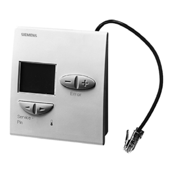
Essentially, the service terminal consists of the housing, the base plate and the cable for
connection to the controller or room unit. The housing and the base plate are connected
by a snap-fitting mechanism.
RXT20.1 – Service terminal
W
ON
RXT20.1
3
851
RXT20.1
® bus connection)
ORKS
CA2N3851en_02 / 12.01.2007
1/6
Advertisement
Table of Contents

Related Manuals for Siemens DESIGO RXT20.1


Summary of Contents for Siemens DESIGO RXT20.1
- Page 1 DESIGO™ RX Service terminal RXT20.1 • Hand-held service terminal with built-in connecting cable • Controller and room unit status display • Remote operation of DESIGO RXB and RXC room controller service pins • NOT SUITABLE FOR RXB VERSION 2.36 AND HIGHER •...
- Page 2 The housing accommodates a printed circuit board, the function keys, LCD and a socket for the commissioning and service tool. Connecting cable 80084 80444 Base plate Housing Socket for RXT10 commis- sioning and service tool 90044 A Elements for operation Displays room unit status, “wink”...
- Page 3 LCD display If the service terminal is connected to a DESIGO RXB / RXC controller, the start-up rou- Response at start-up tine is as follows: Step Display Description All segments activated for approximately 5 s. Cursor fields may be activated for max. 10 s.* (approx. 3 –...
- Page 4 Temperature setpoint • Temperature setpoint in °C or °F (see "Function key 2") The displayed temperature setpoint comes from the room unit. Static error messages Display Description The address of the service terminal has not been set correctly (see “Hex switch”). Dynamic error mes- Dynamic error messages are displayed for 5 s when they occur.
-
Page 5: Technical Data
Technical data Power supply Operating voltage DC 12 ... 15 V The service terminal receives its supply from the connected controller via the PPS2 interface (SELV low voltage in accordance with HD 384) Power consumption (controller) Max. 0.10 VA Function data Display Type Functions displayed... - Page 6 1 To QAX… room unit 2 To RXC… room controller 3 Not possible without QAX... ! Dimensions All dimensions in mm 80088 © 2000 - 2007 Siemens Switzerland Ltd. Subject to change CA2N3851en_02 / 12.01.2007 RXT20.1 – Service terminal Building Technologies...
Need help?
Do you have a question about the DESIGO RXT20.1 and is the answer not in the manual?
Questions and answers