Table of Contents
Advertisement
Quick Links
Advertisement
Table of Contents
Troubleshooting

Related Manuals for Biotek Synergy HT


Summary of Contents for Biotek Synergy HT
- Page 1 Multi-Mode Microplate Reader Synergy ™ Operator’s Manual...
- Page 3 Synergy HT Multi-Mode Microplate Reader Operator’s Guide October 2012 © 2012 Part Number 7091000 Revision L ® BioTek Instruments, Inc.
- Page 4 BioTek Instruments, Inc. Changes made to the information in this document will be incorporated in new editions of the publication. No responsibility is assumed by BioTek for the use or reliability of software or equipment that is not supplied by BioTek or its affiliated dealers.
-
Page 5: Table Of Contents
Canadian Department of Communications Class A .... xvi User Safety ..............xvii Safety Symbols ............. xviii Chapter 1: Introduction ............1 Synergy HT Multi-Mode Microplate Reader ......2 Features ................3 Package Contents .............. 4 Optional Accessories ............5 Product Support & Service ..........6 ... - Page 6 Run the Absorbance Plate Test ........63 Results and Troubleshooting Tips ........66 Absorbance Liquid Tests ........... 68 Absorbance Liquid Test 1 ..........69 Absorbance Liquid Test 2 ..........71 Absorbance Liquid Test 3 (optional) ....... 74 BioTek Instruments, Inc.
- Page 7 Reassembling the Components ........119 Performance Check ............. 120 Appendix A: Decontamination .......... 123 Purpose ................. 124 Required Materials ............125 Procedure for Models without Injectors ......126 Routine Procedure for Models with Injectors ....... 127 Synergy HT Operator’s Manual...
- Page 8 Appendix D: Specifications ..........179 Technical Specifications ........... 180 General Specifications ..........180 Absorbance Specifications ........... 181 Fluorescence Specifications .......... 183 Models with Injectors ..........185 Appendix E: Instrument Dimensions for Robotic Interface187 Instrument Dimensions for Robotic Interface ...... 188 BioTek Instruments, Inc.
-
Page 9: Contact Information
802-655-4740 (outside the U.S.) Fax: 802-654-0638 E-Mail: tac@biotek.com European Coordination Center/Authorized European Representative ® BioTek Instruments GmbH Kocherwaldstrasse 34 D-74177 Bad Friedrichshall Germany Internet: www.biotek.de Phone: +49 (0) 7136 9680 Fax: +49 (0) 7136 968 111 E-Mail: info@biotek.de Synergy HT Operator’s Manual... -
Page 10: Document Conventions
Note: Bold text is primarily used for emphasis. Topics that apply only to specific Synergy HT models are italic preceded by a notice in italics, for example: Applies only to Synergy HT models with injectors. -
Page 11: Revision History
Chapter 3, Installation: Removed references to “NB” version from description of reader model options (Setting Communication Parameters in KC4, p. 3-12). Chapter 5, Performance Verification/Qualification Tests: Updated Figure 5-1, Sample System Test (p. 5-6 and 5-7). Updated Appendix C, Error Codes. Synergy HT Operator’s Manual... - Page 12 Updated the “Error Codes” appendix with recent information. Additional minor cosmetic changes throughout. Added/modified instructions throughout to support Gen5™, including: Chapter 2, Installation - Added instructions for installing software, establishing BioTek Instruments, Inc.
- Page 13 Precautions. Added ‘Consult Instructions for use’ and ‘IVD’ to Safety Symbols. Chapter 1, Introduction: In the product introduction section, added note that Synergy HT basecode software version 2.24 or greater is required for use with Gen5™. Under ‘Package Contents’ added notice that part numbers are subject to change over time, and updated part numbers for the priming plate and tip priming trough.
- Page 14 Preface: Added a warning to use two people to lift/carry the instrument. Updated the dispense module pinch hazard warning text and symbols. Updated the CE Mark information to include EN 61010-2-081 and EN 61010-2-010. Chapter 2, Installation: Added a warning to use two people to lift/carry the instrument. BioTek Instruments, Inc.
-
Page 15: Intended Use Statement
Warranty and Product Registration Take a moment to review the Warranty information that shipped with your product. Please also register your product with BioTek to ensure that you receive important information and updates about the product(s) you have purchased. You can register online through the Customer Resource Center at www.biotek.com or by calling 888/451-5171 or... -
Page 16: Repackaging And Shipping
Preface Repackaging and Shipping If you need to ship the instrument to BioTek for service or repair, contact BioTek for a Return Materials Authorization (RMA) number, and be sure to use the original packing materials. Other forms of commercially available packaging are not recommended... - Page 17 Some areas of the dispense module can present pinch hazards when the instrument is operating. The module is marked with one of the symbols shown here. Keep hands/fingers clear of these areas when the instrument is operating. Synergy HT Operator’s Manual...
-
Page 18: Precautions
Precautions The following precautions are provided to help avoid damage to the instrument: Caution: Service. The instrument should be serviced by BioTek authorized service personnel. Only qualified technical personnel should perform troubleshooting and service procedures on internal components. Caution: Spare Parts. -
Page 19: Ce Mark
EN 61010-1. “Safety requirement for electrical equipment for measurement, control and laboratory use. Part 1, General requirements.” EN 61010-2-081, “Particular requirements for automatic and semi-automatic laboratory equipment for analysis and other purposes.” Synergy HT Operator’s Manual... -
Page 20: Directive 2002/96/Ec: Waste Electrical And Electronic Equipment
Department of Communications. Le present appareil numerique n'emet pas de bruits radioelectriques depassant les limites applicables aux appareils numerique de la Class A prescrites dans le Reglement sur le brouillage radioelectrique edicte par le ministere des Communications du Canada. BioTek Instruments, Inc. -
Page 21: User Safety
Part 1: General requirements.” • Canadian Standards Association CAN/CSA C22.2 No. 61010-1, “Safety requirements for electrical equipment for measurement, control and laboratory use; Part 1: General requirements.” • EN 61010 Standards, see CE Mark starting on page xv. Synergy HT Operator’s Manual... -
Page 22: Safety Symbols
Attenzione, rischio di schiacciare ed elettrica intrappolarsi Warning, hot surface Warning, potential biohazards Attention, surface chaude Attention, risques biologiques potentiels Warnen, heiße Oberfläche Warnung! Moegliche biologische Giftstoffe Precaución, superficie caliente Atención, riesgos biológicos Attenzione, superficie calda Attenzione, rischio biologico BioTek Instruments, Inc. - Page 23 Recogida selectiva de aparatos eléctricos y electrónicos Dispositivo medico diagnostico in vitro Raccolta separata delle apparecchiature elettriche ed elettroniche Consult instructions for use Consulter la notice d’emploi Gebrauchsanweisung beachten Consultar las instrucciones de Consultare le istruzioni per Synergy HT Operator’s Manual...
- Page 24 Preface BioTek Instruments, Inc.
-
Page 25: Chapter 1: Introduction
Chapter 1 Introduction This chapter introduces the Synergy HT, describes its key features, lists its package contents, and provides contact information for technical assistance. Synergy HT Multi-Mode Microplate Reader ......... 2 Features ................3 Package Contents ..............4 Optional Accessories ............... 5 ... -
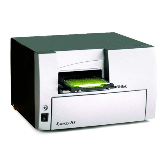
Page 26: Synergy Ht Multi-Mode Microplate Reader
50°C (122°F) that ensures superior temperature uniformity necessary for kinetic assays. Internal plate shaking is also supported. All Synergy HT models support the reading of 6-, 12-, 24-, 48-, 96-, and 384-well microplates with standard 128 x 86 mm geometry, as well as the BioTek Take3 and Take3 Trio Micro-Volume Plates. -
Page 27: Features
Features | Features • Operated using BioTek’s Gen5 Data Analysis Software • Dual-optics design, with separate fluorescence and absorbance channels • 3 mm top and 5 mm bottom fluorescence probes (standard configuration) • Optional 1.5 mm top/bottom, 3 mm bottom fluorescence probes (custom configurations) •... -
Page 28: Package Contents
Chapter 1: Introduction Package Contents Part numbers and package contents are subject to change. Contact BioTek Customer Care with any questions. Item Part # Synergy HT Operator’s Manual 7091000 models with injectors: 76061 Power supply all other models: 76077 Power cord set (specific to installation environment):... -
Page 29: Optional Accessories
BioCell Quartz Vessel and Adapter Plate Additional Fluorescence Filters; contact BioTek for part numbers and availability The Synergy HT is compatible with the BioStack Microplate Stacker. Contact BioTek or visit our website to learn more. For Use with Liquid Tests (see Chapter 5) -
Page 30: Product Support & Service
If your instrument(s) or software fails to function properly, if you have questions about how to use or maintain our products, or if you need to send an instrument to BioTek for service or repair, please contact our Technical Assistance Center. BioTek’s “TAC” is open from 8:30 AM to 5:30 PM (EST), Monday through Friday, excluding standard U.S. - Page 31 Chapter 2 Installation This chapter includes instructions for unpacking and setting up the Synergy HT and, if applicable, the external dispense module. Instructions are also included for repackaging the reader and dispense module for shipment. Product Registration ............... 8 1: Unpack and Inspect the Reader ..........8 ...
-
Page 32: Product Registration
Chapter 2: Installation Product Registration Please register your product with BioTek to ensure that you receive important information and updates about the products you have purchased. Contact the Customer Resource Center (CRC) at www.biotek.com or by calling 888-451-5171 or 802-655-4740. -
Page 33: 1: Unpack And Inspect The Reader
Use two people when lifting and carrying the instrument. The Synergy HT is attached to a shipping panel that has two handles for lifting. Locate and grasp the handles. Carefully lift the reader out of the box and place it on a level surface. -
Page 34: 2: Remove The Shipping Panel
Do not block any air vents. See Figure 3 on the next page. Place the panel back into the inner shipping box for storage. Important: Reattach the shipping panel before repackaging the Synergy HT for shipment. BioTek Instruments, Inc. - Page 35 2: Remove the Shipping Panel | Figure 2: Removing the shipping panel Figure 3: Storage pocket on the rear of the instrument (wrench, carrier shipping screw, and warning tag shown) Synergy HT Operator's Manual...
-
Page 36: 3: Remove The Microplate Carrier Shipping Screw
Figure 4: Removing the microplate carrier shipping screw Replace the microplate carrier shipping Important: screw before repackaging the Synergy HT for shipment. Please contact BioTek if you have misplaced the screw (PN 7092071) and/or its o-ring (PN 49259). BioTek Instruments, Inc. -
Page 37: 4: Install The Fluorescence Lamp Assembly
Plug the lamp cables into the power source located to the right of the lamp. Either cable can be plugged into either socket. Close the hinged door. Figure 5: Installing the fluorescence lamp assembly (replacement lamp PN 7080500) Synergy HT Operator's Manual... -
Page 38: 5: Select An Appropriate Location
Chapter 2: Installation 5: Select an Appropriate Location Install the Synergy HT on a level surface in an area where ambient temperatures between 18ºC (64ºF) and 40ºC (104ºF) can be maintained. The reader is sensitive to extreme environmental conditions. Avoid the following: •... -
Page 39: 7: Unpack And Inspect The Dispense Module
Applies only to Synergy HT models with injectors. Important! Save all packaging materials. If you need to ship the dispense module to BioTek for repair or replacement, you must use the original materials. Using other forms of commercially available packaging, or failing to follow the... - Page 40 Lift out the module and place it on a level surface. Cardboard insert Shipping insert Reagent bottle holders Dispense Dispense module module Inner Inner shipping shipping box Figure 8: Unpacking the dispense module’s inner shipping box BioTek Instruments, Inc.
- Page 41 1 injector tip priming trough (small, plastic cup) • 1 plastic tool storage bag with fastener strips • 2 metal thumbscrews • 1 stylus (wire) packaged in a small plastic cylinder • 1 dispense module cover • 1 dispense module cable Synergy HT Operator's Manual...
- Page 42 Chapter 2: Installation Dispense module Top foam cable end cap Dispense module cover Inlet tubes (2) Syringes (2) Outlet tubes (4) Bottom foam end cap (with cutouts) Accessories Figure 9: Unpacking the dispense module’s accessories BioTek Instruments, Inc.
-
Page 43: 8: Install The Dispense Module
See the photos on the next page. On the rear panel of the Synergy HT, identify the SYRINGE 1 SYRINGE 2 tubing ports. Remove the nylon screws from both ports. Open two of the plastic bags containing the outlet tubes (labeled as PN 7082120). - Page 44 Chapter 2: Installation Figures 10 and 11: Possible locations for the dispense module, to the left or on top of the instrument. Outlet Inlet tubes tubes Syringe valves Figure 12: Initial setup of the dispense module BioTek Instruments, Inc.
- Page 45 Hold the syringe from rotating while tightening the thumbscrew. Finger-tighten only. The installed syringes should resemble the following: Syringes Syringe brackets Thumbscrews Figure 13: The dispense module with the syringes installed Synergy HT Operator's Manual...
- Page 46 . Plug one end into the port on the left side of the cable dispense module. Plug the other end into the “Dispenser Port” on the rear panel of the Synergy HT. One end of the cable connected to the port on...
-
Page 47: 9: Connect The Host Computer
Getting Started Guide 11: Turn on the Reader Locate the power switch on the front panel and turn on the Synergy HT. The reader will automatically initiate a System Test and eject the microplate carrier. Synergy HT Operator's Manual... -
Page 48: 12: Establish Communication
COM port to which the reader is connected. • If using the USB cable, the information can be found via the Windows Control ® Panel, under Ports in the Hardware/Device Manager area of System Properties (e.g., USB Serial Port (COM5)). BioTek Instruments, Inc. -
Page 49: 13: Run A System Test
If the problem is something you can fix, do so now and run another System Test. If the problem is something you cannot fix, or if the test continues to fail, contact BioTek’s Technical Assistance Center. -
Page 50: 14: Test The Injector System
Chapter 2: Installation 14: Test the Injector System Applies only to Synergy HT models with injectors. If necessary, press the button above the power switch to eject the microplate carrier. Place the tip priming trough in the left-rear pocket of the carrier. - Page 51 The fluid should pump through the tubing and dispense into the priming plate. Examine the fittings; no leaks should be detected. If leaks are detected, tighten all fittings and repeat the prime. If leaks are still detected, contact BioTek’s Technical Assistance Center. When the prime finishes, set Volume 2000 µL...
-
Page 52: Operational/Performance Qualification
Chapter 2: Installation Operational/Performance Qualification Your Synergy HT Multi-Detection Microplate Reader was fully tested at BioTek prior to shipment and should operate properly following the successful completion of the installation and setup procedures described throughout this chapter. If you suspect that problems occurred during shipment, if you received the reader back... - Page 53 Please contact BioTek if you have misplaced either of these items. If you need to ship the Synergy HT and/or the dispense module to BioTek for service or repair, be sure to use the original packaging materials.
- Page 54 Perform these steps to prepare the dispense module for shipment: If you have not already done so: • Contact BioTek’s Technical Assistance Center for an (Return Materials Authorization) number and shipping address before returning equipment for service. See page 6 for contact information. •...
- Page 55 Insert the accessories box alongside the dispense module box. Insert the top foam end cap. Close and seal the outer box with tape. Write the RMA number in large clear numbers on the outside of the box. Ship the box to BioTek. Synergy HT Operator's Manual...
- Page 56 Chapter 2: Installation BioTek Instruments, Inc.
-
Page 57: Chapter 3: Getting Started
Chapter 3 Getting Started This chapter describes some of the Synergy HT’s key components and provides an introduction to using Gen5 to control the instrument. Key Components ..............34 Power Switch, Carrier Eject Button, Microplate Carrier ... 34 Lamp Assembly and Filter Wheel Access ......35 ... -
Page 58: Key Components
In Gen5, this option is found in a Read step within a Procedure. Refer to the software documentation for further instructions. BioTek Instruments, Inc. -
Page 59: Lamp Assembly And Filter Wheel Access
“TR” cartridge before running a time-resolved fluorescence assay. See page 39 for more information on the TR cartridge. The Synergy HT has two lamps: one for standard fluorescence, one for absorbance and time-resolved fluorescence: Standard Fluorescence: The 20-watt tungsten halogen lamp’s life is... -
Page 60: Excitation And Emission Filter Wheels
Chapter 3: Getting Started Excitation and Emission Filter Wheels All Synergy HT models are equipped with one Excitation filter wheel and one Emission filter wheel, for use with fluorescence and luminescence measurements. (A monochromator is used for absorbance measurements.) A filter in the Excitation wheel selects the narrow band of light to which the sample will be exposed. - Page 61 Key Components | Important! The Synergy HT is shipped with a set of Excitation and Emission filters installed, and the Synergy’s onboard software is pre-configured with the filter values and their locations. If you change the contents of a filter wheel, you must update Gen5’s filter table and then download the information to the...
- Page 62 Clean both sides of the filter with lens paper. To reinstall a filter wheel: Ensure that all filters and/or plugs are inserted properly (see above). Slide the filter wheel back into its chamber. Replace the thumbscrew. Close the front door. Turn on the instrument. BioTek Instruments, Inc.
-
Page 63: Installing The Time-Resolved Fluorescence Cartridge
Key Components | Installing the Time-Resolved Fluorescence Cartridge For Synergy HT models that support time-resolved fluorescence, the “TR” cartridge must be installed in place of the Excitation filter wheel before a TRF assay can be run. The TR cartridge allows light from the xenon flash bulb to be input to the fluorescence optical system within the Synergy instrument. -
Page 64: Configuring The System For Luminescence Measurements
Updating Gen5’s filter table; for complete instructions, see page 44. • When defining a filter set in a Read step in a Gen5 procedure, selecting “Hole” indicates the empty location in the Emission filter wheel. See page 45 for information on Read steps and procedures. BioTek Instruments, Inc. -
Page 65: The External Dispense Module
Outlet tubes transport fluid from the syringes into the instrument, through the tubing ports on the Synergy HT’s rear panel. The outlet tubes are opaque PTFE tubes with threaded fittings on each end that are used to deliver fluid from the syringes to the instrument. - Page 66 Chapter 3: Getting Started Inside the Synergy HT, two Teflon tubes transport fluid from the tubing ports on the rear of the instrument to the two injectors. As shown below, both injectors are positioned directly above the bottom fluorescence optical probe.
- Page 67 Tip Prime before dispensing. The trough holds up to 1.5 ml of liquid and must be periodically emptied and cleaned by the user. Priming plate Tip priming trough Figure 25: Priming plate and tip priming trough Synergy HT Operator's Manual...
-
Page 68: Gen5 Software
Viewing/Updating the Filter and Wavelengths Tables The Synergy HT ships with a set of Excitation and Emission filters installed, and the reader’s onboard software is pre-configured with the filter values and their locations. -
Page 69: Creating Protocols And Experiments
You’ll run the experiment to read Experiment plates and analyze the data. Figure 26: Defining the Procedure within a Gen5 Protocol Figure 27: An Experiment (containing measurement data), based on a pre-defined protocol Synergy HT Operator's Manual... - Page 70 Select Protocol > Procedure . If prompted to select a reader, select the Synergy HT and click Select a plate type. The assay plate must match the plate type selected in Gen5. Otherwise, the results of the read may be invalid.
- Page 71 Gen5 Software | Synergy HT Operator's Manual...
- Page 72 When the read is complete, measurement values will appear in Gen5. To view them, select the desired data set (e.g., “528/20,645/40”) from the Data drop-down list. If you have not already done so, save the file with an identifying name. BioTek Instruments, Inc.
-
Page 73: Controlling The Dispense Module
Gen5 Software | Controlling the Dispense Module Applies only to Synergy HT models with injectors. Gen5 is used to perform several dispense module-specific functions, including initializing, priming, and purging. Gen5 also contains certain configuration items that must be set before using the dispense module. Read the following sections to become familiar with these functions and configuration items. - Page 74 Gen5 provides a special utility to purge fluid from the dispense tubing and syringe by pumping the fluid in reverse, back into the supply bottle. To purge the dispense module: In Gen5, select System > Reader/Instrument Control > Synergy HT (Com<#>) and click the Dispenser tab.
-
Page 75: Recommendations For Optimum Performance
Gen5 protocol in advance as well, to ensure that the intended reading parameters are used and to avoid any last-minute corrections. • Although the Synergy HT supports standard flat, U-bottom, and V-bottom microplates, the reader achieves optimum performance with optically clear, flat- bottomed wells. See... - Page 76 When dispensing volumes less than or equal to 20 µL/well, we recommend specifying a tip prime volume that is equal to the dispense volume. For dispense volumes greater than 20 µL/well, we recommend a tip prime volume of 20 µL. BioTek Instruments, Inc.
-
Page 77: Chapter 4: Instrument Qualification
Chapter 4 Instrument Qualification This chapter contains procedures for qualifying the initial and ongoing performance of the Synergy HT and the external dispense module (if used). Overview ................54 IQ/OQ/PQ ................54 Recommended Qualification Schedule ........56 System Test ................ 57 ... -
Page 78: Overview
Operational Qualification (OQ), and Performance Qualification (PQ) procedures for all models of the Synergy HT Multi-Mode Microplate Reader. Every Synergy HT reader and external dispense module is fully tested at BioTek prior to shipment and they should operate properly upon initial setup. If you suspect that a... - Page 79 This frequency may be adjusted depending on the trends observed over time. • The successful completion of the PQ procedure confirms that the equipment is performing consistently under normal operating conditions. Synergy HT Operator's Manual...
-
Page 80: Recommended Qualification Schedule
** Liquid Test 3 is optional; it is provided for sites requiring verification at wavelengths lower than those attainable with the Absorbance Test Plate. Important! The risk factors associated with your assays may require that the Operational and Performance Qualification procedures be performed more frequently than shown above. BioTek Instruments, Inc. -
Page 81: System Test
If your assays use incubation, we recommend enabling Temperature Control and allowing the incubator to reach its set point before running the System Test. To access this feature, select System > Reader/Instrument Control > Synergy HT (COM #) and click the Pre-Heating tab. - Page 82 If the test continues to fail, or if the cause is not something you can fix, contact BioTek’s Technical Assistance Center (see page 6 for contact information.) Turn off the incubator.
- Page 83 Resets: 1 Channel: Air: 12705 39020 Dark: 9868 9896 Delta: 2837 29124 Lambda: 999 Gain: 4.49 Resets: 1 Channel: Air: 13084 39360 Dark: 9865 9911 Delta: 3219 29449 Figure 29: Sample output for the System Test Synergy HT Operator's Manual...
- Page 84 Delta 1: 11244 -11232= Delta 2: 2552 - 2544= Delta 3: 1852 - 1856= Delta 4: 7376 - 7376= Probe Height: 32.48 Middle Sensor: y= 11976 Tested: 11972 Delta: Back Sensor: x= 11588 y= 7964 Tested: 11580 7976 Delta: BioTek Instruments, Inc.
- Page 85 BioTek Instruments, Inc. BioTek Instruments GmbH Tel: 800 242 4685 Tel: 49 (0) 7136-9680 Fax: 802 655 3399 Fax: 49 (0) 7136-968-111 All Others: Tel: 802 655 4040 Fax: 802 655 3399 email: TAC@biotek.com Product support center: www.biotek.com/service Synergy HT Operator's Manual...
-
Page 86: Absorbance Plate Test
(PN 7260522) to confirm the mechanical alignment; optical density accuracy, linearity, and repeatability; and wavelength accuracy of the Synergy HT. The Absorbance Plate Test compares the reader’s optical density and wavelength measurements to NIST-traceable values. An alternate method that may be used to determine accuracy, linearity, and repeatability is Liquid Test 2, described on page 71. -
Page 87: Run The Absorbance Plate Test
Comments Click Start Test. Place the Test Plate in the microplate carrier so that well A1 is in the left rear corner of the carrier (as you are facing the carrier). Click to run the test. Synergy HT Operator's Manual... - Page 88 A sample test report is shown on page 65. • Gen5 stores the results in a database; they can be retrieved and printed at any time. We recommend you print and save the report to document that the test was performed. BioTek Instruments, Inc.
- Page 89 0.999 1.509 1.808 2.284 Max Limit 0.159 0.599 1.081 1.611 1.922 2.516 Read 1 0.134 0.566 1.037 1.557 1.866 2.385 Result PASS PASS PASS PASS PASS PASS Figure 30: Sample output for the Absorbance Plate Test Synergy HT Operator's Manual...
-
Page 90: Results And Troubleshooting Tips
Make sure the Test Plate is within its calibration certification period. The calibration sticker is affixed directly to the plate. If it is out of date, contact BioTek to schedule a recertification. Check the microplate carrier to ensure it is clear of debris. - Page 91 Test Plate’s data sheet. Verify that the Test Plate is within its calibration certification period. The calibration sticker is affixed directly to the plate. If it is out of date, contact BioTek to schedule a recertification. • Repeatability: Repeatability is a measure of the instrument’s ability to read...
-
Page 92: Absorbance Liquid Tests
Chapter 4: Instrument Qualification Absorbance Liquid Tests Conducting Liquid Tests confirms the Synergy HT’s ability to perform to specification with liquid samples. Liquid testing differs from testing with the Absorbance Test Plate in that liquid in the wells has a meniscus, whereas the Test Plate’s neutral density glass filters do not. -
Page 93: Absorbance Liquid Test 1
Stock Solution A or B, which may be formulated by diluting a dye solution available from BioTek (A) or from the ingredients listed below (B). Solution A • BioTek QC Check Solution No. 1 (PN 7120779, 25 mL; PN 7120782, 125 mL) • Deionized water •... - Page 94 ± 1.0% ± 0.010 OD, then the expected range for the mean of the same well in its Turnaround (H12) position is 1.873 to 1.931 OD. 1.902 x 0.010 + 0.010 = 0.029; 1.902 - 0.029 = 1.873; 1.902 + 0.029 = 1.931 BioTek Instruments, Inc.
-
Page 95: Absorbance Liquid Test 2
80% in the third tube, all the way to 10% in the tenth tube. Dilute using the 0.05% solution of deionized water and Tween 20. This solution can also be made by diluting the BioTek wetting agent 200:1. Test Tube Dilutions... - Page 96 (0.0195 + 0.005) = 0.0245 OD, which is the allowable deviation. Since the standard deviation is less than this value, the reader meets the test criteria. Repeatability Specification: ± 1.0% ± 0.005 OD from 0.000 to 2.000 OD ± 3.0% ± 0.005 OD from 2.000 OD to 3.000 OD BioTek Instruments, Inc.
- Page 97 H12 position is 1.873 to 1.931 OD. (1.902 x 1.0% = 0.019 + 0.010 = 0.029, which is added and subtracted from 1.902 for the range.) If the four corner wells are within the accuracy range, the reader is in alignment. Synergy HT Operator's Manual...
-
Page 98: Absorbance Liquid Test 3 (Optional)
(or equivalent) • β-NADH Powder (β-Nicotinamide Adenine Dinucleotide, Reduced Form) Sigma bulk catalog number N 8129, or preweighed 10-mg vials, Sigma number N6785-10VL (or BioTek PN 98233). Note: Manufacturer part numbers are subject to change. Store the β-NADH Powder according to the guidelines on its packaging. - Page 99 (mean of wells A1 to H2, A3 to H4, and A5 to H6). • Perform a regression analysis on the data to determine if there is adequate linearity on a program such as Microsoft Excel: ® Synergy HT Operator's Manual...
-
Page 100: Fluorescence Tests
Corners Test uses fluorescent compounds to verify that the plate carrier is properly aligned in relation to the optical probe(s). (Because the Synergy HT’s fluorescence optics are different from the absorbance optics, the Corners Test is also required.) We recommend running the test for both the top and bottom probes (if equipped). -
Page 101: Required Materials
Fluorescence Tests | Required Materials BioTek offers a liquid test kit (PN 7160013) containing the microplates and solutions used in this procedure. Microplates should be perfectly clean and free of dust or bottom scratches. Use new microplates from sealed packages. -
Page 102: Test Solutions
Chapter 4: Instrument Qualification Test Solutions If using BioTek’s sodium fluorescein powder (PN 98155), be sure to hold the vial upright and open it carefully; the material may be concentrated at the top. If a centrifuge is available, spin down the tube before opening. -
Page 103: Procedure
Bottom 5 mm 26 pM (10 pg/mL) Bottom 3 mm 53 pM (20 pg/mL) Bottom 1.5 mm 106 pM (40 pg/mL) Top 3 mm 53 pM (20 pg/mL) Top 1.5 mm 106 pM (40 pg/mL)* * Typical performance Synergy HT Operator's Manual... -
Page 104: Troubleshooting
Troubleshooting If any tests fail, please try the suggestions below. If the test(s) continue to fail, print the results and contact BioTek’s Technical Assistance Center. • Are the solutions fresh? The open buffer and stock solutions should be discarded after seven days. -
Page 105: Pipette Map
Aspirate 150 µL from wells C5-F5 and discard. CBUF CBUF CBUF CBUF CBUF CBUF CBUF CBUF CBUF CBUF 0.25 0.125 0.062 0.25 0.125 0.062 0.25 0.125 0.062 0.25 0.125 0.062 CBUF CBUF CBUF CBUF CBUF CBUF CBUF CBUF CBUF CBUF Synergy HT Operator's Manual... -
Page 106: Gen5 Protocol Reading Parameters
Plate Type or Gain (Sensitivity) (see “Troubleshooting” on page 80). The Plate Type setting should match the plate you are actually using. Protocol Name: Synergy HT FI_B.prt Parameter Setting Plate Type: “Greiner SensoPlate”... -
Page 107: Fluorescence Tests Using Methylumbelliferone
Required Materials BioTek offers a liquid test kit (PN 7160012) containing the microplate and solutions used in this procedure. Microplates should be perfectly clean and free of dust or bottom scratches. Use new microplates from sealed packages. - Page 108 85 and pipette the solutions into a clean, 96-well solid black plate. 4. Read the plate using the protocol. Synergy HT FI_MUB.prt 5. Save and/or print the measurement data. 6. Calculate and analyze the results as described below. Results Analysis Sensitivity Test 1.
- Page 109 • Aspirate 150 µL from wells C4-F4 and dispense it into wells C5-F5. Mix the wells using the pipette. • Aspirate 150 µL from wells C5-F5 and discard. 12.5 6.25 12.5 6.25 12.5 6.25 12.5 6.25 Synergy HT Operator's Manual...
-
Page 110: Dispense Module Tests
Dispense Module Tests Applies only to Synergy HT models with injectors. BioTek Instruments, Inc. has developed a set of tests that you can perform to ensure that the dispense module performs to specification initially and over time. We recommend that you perform these tests before first use (e.g., during the Initial OQ), and then every three... -
Page 111: Required Materials
± 1.0% ± 0.010 OD or better and a repeatability specification of ± 1.0% ± 0.005 OD or better. The Synergy HT reader may be used if it has passed the Absorbance Plate Test and the Absorbance Liquid Tests described earlier in this chapter. -
Page 112: Alternate Test Solutions
1.300 and 1.700 OD at 405/750 nm. It is assumed that the solutions used are at room temperature. If you do not have BioTek’s Green Test Dye Solution (PN 7773003), prepare a green test dye solution using one of the following methods: Using BioTek’s Blue and Yellow Concentrate Dye Solutions:... -
Page 113: Test Setup
(BioTek PN 7082118) is installed in the microplate carrier. • Place a clean priming plate (BioTek PN 7132158 or 7092135) on the carrier. • Fill a supply bottle with deionized or distilled water and insert the inlet tube. • In Gen5, select . - Page 114 When processing is complete, save the experiment using an identifying file name. Repeat steps 4–9 using the Synergy HT Dispenser 2.prt protocol. See page 91 for instructions for analyzing the results. When all tests are complete, prime both dispensers with at least 5000 µL of deionized or distilled water, to flush out the green dye solution.
-
Page 115: Results Analysis
If any tests fail, prime the fluid lines and rerun the test(s). If the test(s) fail again, the injector heads may require cleaning (see Chapter 5, Preventive Maintenance If tests continue to fail, contact BioTek’s Technical Assistance Center. Synergy HT Operator's Manual... -
Page 116: Creating The Test Protocols
Chapter 4: Instrument Qualification Creating the Test Protocols This section contains instructions for creating two Gen5 protocols specifically for performing the Synergy HT Dispense Precision and Accuracy test. Refer to the Gen5 Help system to learn more about using Gen5, and for complete instructions for creating protocols. - Page 117 Standard Deviation, Mean, and % CV of the ODs read for each dispense volume in each plate (six sets of calculations). By identifying the wells by their dispense volumes in the Plate Layout, Gen5 will calculate these values for you. Synergy HT Operator's Manual...
- Page 118 DS1-DS2 When you’re finished, the Data Reduction Steps list will show two Delta OD transformations. Click to close the Data Reduction dialog. Save the protocol with an identifying file name, such as “Synergy HT Dispenser 1.prt”. BioTek Instruments, Inc.
-
Page 121: Chapter 5: Preventive Maintenance
Chapter 5 Preventive Maintenance This chapter provides step-by-step instructions for maintaining the Synergy HT and external dispense module (if used) in top condition, to ensure that they continue to perform to specification. Recommended Maintenance Schedule ........96 Overview ................ 96 ... -
Page 122: Recommended Maintenance Schedule
(review the reagent’s package insert for specific recommendations). A daily cleaning regimen is the best way to ensure accurate performance and a long- life for your instrument and dispense module. BioTek also recommends flushing the module with DI water before conducting the decontamination procedure described in Appendix A BioTek Instruments, Inc. -
Page 123: Recommended Maintenance Schedule
Models with injectors only: Flush/purge the fluid path (Optional) Run Dispense protocol Empty/clean tip prime trough Clean priming plate Clean internal components tubing and injector heads Clean optical probes Clean internal surfaces Synergy HT Operator's Manual... -
Page 124: Warnings & Precautions
“wet” cloth on it. Do not allow water or other cleaning solution to run into the interior of the instrument. If this happens, contact BioTek’s Technical Assistance Center. Important! Do not apply lubricants to the microplate carrier or carrier track. -
Page 125: Cleaning Exposed Surfaces
“wet” cloth. Do not allow the cleaning solution to run into the interior of the instrument. If this happens, contact BioTek’s Service Department. Exposed surfaces may be cleaned (not decontaminated) with a cloth moistened (not soaked) with water or water and a mild detergent. You will need: •... -
Page 126: Inspect/Clean Excitation And Emission Filters
Clean the filters using lens-cleaning tissue moistened with a small amount of isopropyl, ethyl, or methyl alcohol. Ensure that the filters remain in their current locations. Replace the filter wheel brackets in their respective positions and replace the thumbscrews. Close the hinged door. BioTek Instruments, Inc. -
Page 127: Flush/Purge The Fluid Path
Flush/Purge the Fluid Path | Flush/Purge the Fluid Path Applies only to Synergy HT models with injectors. At the end of each day that the dispense module is in use, flush the fluid path using Gen5’s priming utility. Leave the fluid to soak overnight or over a weekend, and then purge the fluid before using the instrument again. -
Page 128: Running A Dispense Protocol (Optional)
Chapter 5: Preventive Maintenance Running a Dispense Protocol (Optional) Applies only to Synergy HT models with injectors. After flushing/purging the system (page 101) and before running an assay that requires dispense, take a moment to visually inspect the dispensing accuracy. -
Page 129: Empty/Clean The Tip Priming Trough
104. Empty/Clean the Tip Priming Trough Applies only to Synergy HT models with injectors. The tip priming trough is a small, removable priming cup located in the left rear of the microplate carrier, used for performing the Tip Prime. The trough holds about 1.5 mL of liquid and must be periodically emptied and cleaned by the user. -
Page 130: Clean The Internal Components
Chapter 5: Preventive Maintenance Clean the Internal Components Applies only to Synergy HT models with injectors. The Synergy HT’s internal components that require routine cleaning include: • Optical probes • Surface beneath the microplate carrier • Internal dispense tubes and injector heads The internal components should be cleaned at least quarterly. -
Page 131: Required Materials
Deionized or distilled water • Stylus (stored in a plastic cylinder affixed to the rear of the dispense module or reader) (PN 2872304) For cleaning the optical probes: • Clean cotton swabs • Isopropyl alcohol • Lens-cleaning tissue Synergy HT Operator's Manual... -
Page 132: Removing The Reader's Shroud
Remove two screws from the top center of the rear panel Remove two side screws When reinstalling the shroud, press down firmly on the top to maintain a good light seal while tightening the top screws. BioTek Instruments, Inc. - Page 133 Clean the Internal Components | Stand facing the front of the instrument. Grasp both sides of the shroud, slide it toward you, and pull it straight off the instrument. Set the shroud aside. Synergy HT Operator's Manual...
-
Page 134: Removing The Internal Tubes And Injector Heads
SYRINGE 1 SYRINGE 2 Important! When reinstalling the internal dispense tubes, be sure to align the tubing ports with the injector heads as shown in this diagram. Look for the SYRINGE 1 SYRINGE 2 labels on the instrument’s rear panel. BioTek Instruments, Inc. - Page 135 Locate the tubing ports on the reader’s rear wall. Turn each tube’s thumbscrew counterclockwise and gently pull the tube from the port. Cable clamp Locate the injector heads. Turn each tube’s thumbscrew counterclockwise to disconnect the tube from the injector head. Synergy HT Operator's Manual...
- Page 136 Chapter 5: Preventive Maintenance Turn the injector heads counterclockwise and gently pull them out of their sockets. Be sure to seat the injector tips securely when reinstalling. See the photo on page 121. BioTek Instruments, Inc.
-
Page 137: Cleaning The Internal Tubes And Injector Heads
Stream water from a faucet through the pipe to be sure it is clean. If the water does not stream out, try soaking the heads in hot soapy water and then reinserting the stylus. O-ring; do not remove Synergy HT Operator's Manual... -
Page 138: Cleaning The Optical Probes
(cover). If you haven’t already done this, turn to page 106 now for instructions. Note: For models without injectors, the internal chamber and probes are not customer-accessible. Contact BioTek’s Technical Assistance Center with any questions about your particular model. •... - Page 139 Top optical probe Screw for lowering and raising the top optical probe Incubator Top probe hanger, with housing two shoulder screws Figure 32: Internal components to be removed/adjusted for cleaning the optic probes Synergy HT Operator's Manual...
- Page 140 Disconnect the heater and thermistor wires. To do this, depress the small tab (pictured below) and separate the connectors. Depress tab to separate the connectors Remove the thumbscrew located in the left rear of the instrument and set it aside. This exposes the ground wire. BioTek Instruments, Inc.
- Page 141 Clean the Internal Components | Lift the ground wire and move it off to the side. Locate the two black thumbscrews that hold the incubator housing in place. Remove both of them and set them aside. Synergy HT Operator's Manual...
- Page 142 Gently lift the left side of the incubator housing and carefully slide it out. Note: When replacing the incubator housing, the two “forks” on its right side should wrap around the holding screws. The forks should not slide under the fixed foam housing. BioTek Instruments, Inc.
- Page 143 Gently pull the optical probe up and out of its socket to expose it for cleaning. Soak the probe in alcohol for one minute maximum . Wipe with lens-cleaning tissue and set aside. Clean with alcohol and lens tissue Synergy HT Operator's Manual...
- Page 144 (see instructions on the next page). Do not touch the lens with your fingers! Inspect the block for spills or other contamination. Carefully clean with mild detergent if necessary. Absorbance Lens Probe hanger (bottom view) BioTek Instruments, Inc.
- Page 145 Important! When cleaning the absorbance lens with the swab, apply very little pressure to the lens! Applying too much pressure can push the lens out of its holder; reinstallation must be performed by BioTek service personnel. If the lens does fall out, contact BioTek TAC.
-
Page 146: Cleaning The Reader's Internal Surface
Microplate carrier, fully extended Moisten ( do not soak ) a clean cotton cloth with alcohol, water, or with water and mild detergent. Wipe all sides of the plate carrier. Wipe the instrument’s horizontal surface. BioTek Instruments, Inc. -
Page 147: Reassembling The Components
The knurled plastic should sit flush against the hanger surface, as shown below. Attach the two internal dispense tubes to the injector heads, as shown below. Do not overtighten the thumbscrews! Synergy HT Operator's Manual... -
Page 148: Performance Check
After reassembling the instrument, perform the following to verify that the instrument is functioning properly: • Plug the instrument in and turn it on; allow its run-time system test to complete. Run a System Test through Gen5. • Run any required OQ/PQ tests. BioTek Instruments, Inc. - Page 149 Appendix A Decontamination This appendix contains procedures for decontaminating all models of the Synergy HT. Purpose ................124 Required Materials ............... 125 Procedure for Models without Injectors ........126 Routine Procedure for Models with Injectors ......127 Clean Exposed Surfaces ........... 127 ...
-
Page 150: Appendix A: Decontamination
Centers for Disease Control and Prevention (CDC). Neither BioTek nor the CDC assumes any liability for the adequacy of these solutions and methods. Each laboratory must ensure that decontamination procedures are adequate for the Biohazard(s) they handle. -
Page 151: Required Materials
Required Materials | 125 Required Materials For all Synergy HT models: • Sodium hypochlorite (NaClO, or bleach) • 70% isopropyl alcohol (as an alternative to bleach) • Deionized or distilled water • Safety glasses • Surgical mask • Protective gloves •... -
Page 152: Procedure For Models Without Injectors
Do not immerse the instrument, spray it with liquid, or use a “wet” cloth. Do not allow the cleaning solution to run into the interior of the instrument. If this happens, contact the BioTek Service Department. Important! Turn off and unplug the instrument for all decontamination and cleaning operations. -
Page 153: Routine Procedure For Models With Injectors
Routine Procedure for Models with Injectors Perform this Routine Procedure when all systems are functioning normally on the Synergy HT with Injectors. If you are unable to prime the Synergy HT due to a system failure, perform the Alternate Procedure described on page 131. -
Page 154: Decontaminate The Fluid Lines
Put the tubes back in. Important! If sodium hypochlorite (bleach) was used, perform Rinse the Fluid Lines on the next page. Otherwise, (or after performing the Rinse procedure), repeat steps 1–13 for SYRINGE 2 Dispenser 2 BioTek Instruments, Inc. -
Page 155: Rinse The Fluid Lines
• Required Materials • Removing the Reader’s Shroud • Removing the Internal Tubes and Injector Heads • Cleaning the Internal Tubes and Injector Heads When finished, replace the internal components and the reader’s shroud. Synergy HT Operator's Manual... -
Page 156: Clean The Tip Priming Trough And Priming Plate
If decontaminating with alcohol , remove the trough and plate and let them air- dry. Discard the used gloves and cloths using a biohazard trash bag and an approved biohazard container. Figure 33: Tip priming trough and priming plate BioTek Instruments, Inc. -
Page 157: Alternate Procedure For Models With Injectors
Alternate Procedure for Models with Injectors | 131 Alternate Procedure for Models with Injectors If you are unable to prime the Synergy HT due to a system failure, decontaminate the instrument and the Dispense Module as follows: Turn to Chapter 5, Preventive Maintenance... - Page 158 Use a clean, dry cloth to dry all wet surfaces on the instrument and the Dispense module. Reassemble the instrument and dispense module as necessary. Discard the used gloves and cloths using a biohazard trash bag and an approved biohazard container. BioTek Instruments, Inc.
-
Page 159: Appendix B: Computer Control
The Synergy HT is completely computer-controlled; it is not equipped with a keypad or its own user interface. BioTek’s Gen5 software package supports all Synergy HT models and is used for both instrument control and data reduction. For information on serial protocol commands and/or system integration, please contact your BioTek sales representative or BioTek Instruments, Inc. - Page 160 Appendix B: Computer Control BioTek Instruments, Inc.
- Page 161 Appendix C Error Codes This section lists and describes the possible error codes that may appear on the controlling PC. Error Codes ................ 136 Fatal Errors ..............137 Non-Fatal Errors ............. 138 Home Sensor Initial Find Errors (0100-0307) ....138 Home Sensor Verification Errors (0400-0409) ....
-
Page 162: Appendix C: Error Codes
If you need help or more information, contact BioTek’s Technical Assistance Center. See Chapter 1 for contact information. For errors that are displayed during operation of the Synergy HT with the BioStack Microplate Stacker, refer to the BioStack Operator’s Manual. -
Page 163: Error Codes
Error Codes | Fatal Errors Fatal errors indicate conditions that require immediate attention. If a fatal error is displayed, contact BioTek’s Technical Assistance Center for further instructions. Code Description Task block not available A100 control A200 Read already in progress... -
Page 164: Non-Fatal Errors
Loosen the two screws and slide the PCB to the right and retighten. Run the carrier autocal for both absorbance and fluorescence. • Carrier is not able to move into read chamber. An object may be obstructing the carrier’s path. • See Field Change Notice L0030. BioTek Instruments, Inc. - Page 165 • Filter wheel is not moving because it is too close to the motor gear and is binding. • Defective or broken optical sensor. • Defective motor, Motor Controller PCB, or cable. • Motors failed due to the bearings. Synergy HT Operator's Manual...
- Page 166 • Defective motor, Motor Controller PCB, or cable. • Cable between the dispenser and the Synergy is defective, too long, or there is a lost connection. • For certain older dispensers, opto cable 7330506 may need to be replaced with 7120734. BioTek Instruments, Inc.
- Page 167 This error is caused when the Order-sorting Filter Wheel cannot rotate to the home sensor position. Probable Causes: • The motor or motor driver circuit is defective. • The home sensor or sensor circuit is defective. Synergy HT Operator's Manual...
-
Page 168: Home Sensor Verification Errors (0400-0409)
Probable Causes: • The optical trigger flag has moved or is loose. • Dirty rail, nylon bushings, or bearings. • Carrier support pin is out of adjustment. • Reference Field Change Notice L0030. BioTek Instruments, Inc. - Page 169 Reference Field Change Notice L0031. • Fiber-optic cable is not tied to the upper probe assembly, and has moved into the top probe’s path, not allowing the top probe to reach the optical sensor. Synergy HT Operator's Manual...
-
Page 170: Saturation Errors (0500-0616)
(filter wheels homing), a 0500 error could indicate a missing filter. In this case, a 0501 would indicate a missing filter in position 1 of the wheel, which was last homing prior to the error condition being detected. BioTek Instruments, Inc. - Page 171 PCB sent the wrong voltage request to the lamp power supply. Scenario 4 (fluorescence autocalibration): • The surface of the autocalibration jig is too reflective. Return the jig to BioTek for a replacement jig. • The carrier did not move far enough to block the light beam. Troubleshoot the carrier movement.
- Page 172 • Voltage to the lamp has increased due to failure of the lamp power supply, or the motor power supply PCB sent the wrong voltage request to the lamp power supply. BioTek Instruments, Inc.
- Page 173 • Voltage to the lamp has increased due to failure of the lamp power supply, or the motor power supply PCB sent the wrong voltage request to the lamp power supply. Synergy HT Operator's Manual...
- Page 174 • Voltage to the lamp has increased due to failure of the lamp power supply, or the motor power supply PCB sent the wrong voltage request to the lamp power supply. BioTek Instruments, Inc.
- Page 175 • Order-sorting filter wheel is jammed, not aligning the correct bandpass filter with the light path, or the through hole is allowing white light to pass. • Monochromator is defective. • Flash lamp, alignment, or Flash lamp power supply is defective. • Lamp is too bright. Synergy HT Operator's Manual...
-
Page 176: Absorbance Reader Noise Errors (0700-0A16)
Absorbance measurement channel noise test at max gain See noise “Delta” on self-test fail if < 20. This error indicates significant variations in background electronic noise were detected when blocking the light and increasing the gain to maximum. Probable Causes: BioTek Instruments, Inc. - Page 177 • Absorbance channel analog PCB is defective. 0810 Absorbance measurement channel failed offset range See “noise Max” < 20000 and “noise Min” > 10 on the system test. This error indicates that during the system test, the background electronic signal that was Synergy HT Operator's Manual...
- Page 178 The last number is the lambda table position number. This error can indicate one of the following scenarios: • The reference channel failed < 100 during the optic test with the flash on. • The reference channel failed < 100 during a read or blank read not in sweep mode with the BioTek Instruments, Inc.
- Page 179 See “Dark” on the system test. See criteria in text below. The last number is the lambda table position number. This error can indicate one of the following scenarios: • The measurement channel failed < 100 during optic test with the flash on. Synergy HT Operator's Manual...
- Page 180 • Dirty optics or spilled substance on the optics. • Order-sorting filter wheel is jammed, not aligning the correct bandpass filter with the light path, or the filter is degraded and is not passing enough light energy or is blocking the light. BioTek Instruments, Inc.
-
Page 181: Internal Self-Test Errors (0D00-2918)
• Order-sorting filter wheel is jammed, not aligning the correct bandpass filter with the light path and white light is passing through, or the filter is degraded and is not passing enough light energy or is blocking the light. • Damaged optic spray. Synergy HT Operator's Manual... - Page 182 • Order-sorting filter wheel is jammed, not aligning the correct bandpass filter with the light path and white light is passing through, or the filter is degraded and is not passing enough light energy or is blocking the light. • Damaged optic spray. BioTek Instruments, Inc.
- Page 183 This error indicates that no autocal data for any of the three read locations (bottom probe, top probe, absorbance). Probable Causes: • The 7080400 PCB was changed and the Flash memory does not have the calibration values loaded. Performing the autocalibration procedure will correct this. Synergy HT Operator's Manual...
- Page 184 X-axis 0200 1301 Y-axis 0201 1302 EX motor 0202 1303 EM motor 0203 1304 Order-sorting filter wheel 0204 1305 Monochromator 0405 1306 Probe Height 0206 1307 Probe changer 0207 1308 Syringe 1 0208 1309 Syringe 2 0209 BioTek Instruments, Inc.
- Page 185 Zone 2, 3, and 4 150F Zone 1, 2, 3, and 4 Probable Causes: • Thermistor is defective for that zone. • Heating pad is defective. • Motor power supply PCB is defective. • Incubation chamber is less than 12ºC. Synergy HT Operator's Manual...
- Page 186 Zone 3 and 4 151D Zone 1, 3, and 4 151E Zone 2, 3, and 4 151F Zone 1, 2, 3, and 4 Probable Causes: • Thermistor is defective for that zone. • Motor power supply PCB is defective. BioTek Instruments, Inc.
- Page 187 This error indicates that the combination of assay parameters results in more kinetic reads than supported by the software. • Change the assay parameters to reduce the number of total kinetic reads. Note: The Synergy HT supports kinetics through computer control only. Synergy HT Operator's Manual...
- Page 188 30 seconds, and then turning the instrument back on. Probable Causes: • The memory is corrupt. Replace the processor PCB. • If the error persists, contact BioTek TAC. A/D calibration STBY line never went low 1C00...
- Page 189 • Defective Motor Controller PCB. • Shipping screw was not installed before moving the unit, and the XY sensor was damaged. • Something moved the carrier while it was extended. • Faulty motor gear attachment (set screw loose). Synergy HT Operator's Manual...
- Page 190 This error indicates that during a self-test, the lamp did not indicate that it was off. Probable Causes: • The sense resistor is damaged on the 7090402 PCB. • Cable between the lamp PCB and motor power supply PCB is defective. • Motor power supply PCB is defective. BioTek Instruments, Inc.
- Page 191 This test is performed when the instrument is first turned on and then tested periodically during background functions. Probable Causes: • The lamp is weak or defective—change the lamp (BioTek PN 7080500). • The sense resistor is damaged on the 7090402 PCB. • The regulator mounted on the 7090402 PCB is defective.
- Page 192 2901 2912 2902 2913 2903 2914 2904 2915 2905 2916 2906 2917 2907 2918 2908 Probable Causes: • The motor power supply PCB is defective. • The sense resistor is damaged on the motor power supply PCB. BioTek Instruments, Inc.
-
Page 193: Other Errors (2A00-4000)
• Syringe was not installed correctly or was not cleaned, causing stress on syringe movement by not allowing the syringe to move to the home position. • The syringe valve did not open. • The glue between the lead screw and the motor has separated. Synergy HT Operator's Manual... - Page 194 This error indicates that the calibration data has been entered but the checksum failed. This corresponds to the 6 calibration values. Note: This error can apply to either Syringe 1 or Syringe 2. Probable Causes: • Values entered are corrupted or incorrect. BioTek Instruments, Inc.
- Page 195 • The filters defined in the filter table do not match the filter wheels. • The user did not send the filter table information to the reader after making changes to the table in the controlling software. Synergy HT Operator's Manual...
- Page 196 Z position. The distance between the top of the autocalibration jig and the homing opto sensor is <= 24 full steps. Probable Causes: • Linear way is dirty or needs lubrication. • Homing opto sensor is defective. BioTek Instruments, Inc.
- Page 197 Required carrier outside when locked in If the carrier is inside the read chamber and the probe needs to move down but the door is locked, the carrier cannot move out of the way of the top probe assembly. Synergy HT Operator's Manual...
- Page 198 151 152 153 154 155 156 157 158 159 15A 15B 15C 15D 15E 15F 160 161 162 163 164 165 166 167 168 169 16A 16B 16C 16D 16E 16F 170 171 172 173 174 175 176 177 178 179 17A 17B 17C 17D 17E 17F 180 BioTek Instruments, Inc.
-
Page 199: Status String Format
OVERLAP ERR “1F00” bandpass overlap in filterset INVALID PARAM ERR “2100” invalid parameter value selected PMT ERR “2200” PMT test signal out of range <test type> SENSOR POS ERR “2400” <motor> failed verify at test sensor Synergy HT Operator's Manual... - Page 200 Motor Codes <lowest digit in returned error code> Carrier X-Axis “0” Carrier Y-Axis “1” Excitation Filter Wheel “2” Emission Filter Wheel “3” Monochromator Filter Wheel “4” Monochromator “5” Probe Height Axis “6” Probe Changer “7” Dispenser Syringe 1 “8” Dispenser Syringe 2 “9” BioTek Instruments, Inc.
- Page 201 TWO BOTTOM INJECTORS “8” only one injector can be at bottom position Synergy HT Operator's Manual...
- Page 202 “30” number of shake events defined invalid SHAKE START TIME “31” shake start time out of range READ EVENT EXPECTED “32” read event must follow shake event with repeat SHAKE TIME “33” shake time out of range BioTek Instruments, Inc.
- Page 203 Ex: 87 - ((8 - 1) * 12) = column 3. Note: If this code is returned in response to a Run Area Scan (‘c’) command, it indicates the scanned point (left-to-right) that caused the error. Synergy HT Operator's Manual...
- Page 204 Appendix C: Error Codes BioTek Instruments, Inc.
-
Page 205: Appendix D: Specifications
Appendix D Specifications This appendix contains BioTek’s published specifications for the Synergy HT. Technical Specifications ............180 General Specifications ............. 180 Absorbance Specifications ..........181 Fluorescence Specifications ..........183 Models with Injectors ............185 ... -
Page 206: Technical Specifications
Temperature control range from 4º over ambient to 50ºC. Temperature variation ± 0.50°C across the plate @ 37°C (250 µl per well with the plate sealed). Plate Shaking: Low, Medium, High and Variable shaking speeds. Shake time is programmable by the user. BioTek Instruments, Inc. -
Page 207: Absorbance Specifications
2.500 to 3.000 OD ±3.0% ±0.005 OD Normal mode, 96-/384-well plates 0.000 to 1.000 OD ±2.0% ±0.010 OD Sweep mode, 96-/384-well plates Optics 200 to 999 nm λ range: λ accuracy: ± 2 nm λ repeatability: ± 0.2 nm λ bandpass: 2.4 nm Detector: Photodiodes (2) Synergy HT Operator's Manual... - Page 208 Appendix D: Specifications Read Modes The Synergy HT supports the following read modes: Normal mode: The slowest of the three available modes. After positioning the well over the probe, the instrument waits 100 milliseconds before taking the measurement (8-flash data collection). Note: The 100 ms delay is to allow for more complete fluid settling.
-
Page 209: Fluorescence Specifications
275 sec Optical Probes The Synergy HT is configured with a variety of probe sizes: 1.5 and 3 mm probes can be installed in either the top or bottom positions; the 5 mm probe can only be installed in the bottom position. - Page 210 300 μL per well signal-to-noise ratio greater than 2 Excitation 360/40, Emission 460/40 Corning Costar black strips Optional Time-Resolved Fluorescence (“T” models) Times are adjustable in 10 µs increments Delay: 0, or 20 µs to 16000 µs Integration Interval: 20 to 16000 µs BioTek Instruments, Inc.
-
Page 211: Models With Injectors
0.1% Tween 20, and dye at room temperature: < 2.0% for volumes of 50-200 mL < 4.0% for volumes of 25-49 mL < 7.0% for volumes of 10-24 mL < 10.0% for volumes of 5-9 mL Synergy HT Operator's Manual... - Page 212 Appendix D: Specifications BioTek Instruments, Inc.
-
Page 213: Instrument Dimensions For Robotic Interface
Robotic Interface This section shows the location of the microplate carrier in reference to the exterior surfaces of the Synergy HT and the mounting holes on the bottom. The illustration should facilitate system setup with a robotic instrument, such as the BioStack... - Page 214 Appendix E: Instrument Dimensions for Robotic Interface Instrument Dimensions for Robotic Interface If you have purchased the BioStack to operate with the Synergy HT, special alignment hardware is included in the BioStack alignment kit for correct positioning of the Synergy HT with the BioStack.
Need help?
Do you have a question about the Synergy HT and is the answer not in the manual?
Questions and answers
I Connected ELx800 with Gen5 3.12 .When i check the connection it is succeeded because i was make plate in and plate out successfully and message appear that connected successfully .But when i need to run plate or tests the message appear (Reader Failed to acknowledge request) or when i need to make validation it will be fail . I don't know how can I resolve this issue. I sent the errors photo here Thank you
To troubleshoot the "Reader Failed to acknowledge request" error on the Biotek Synergy HT when connected to ELx800 with Gen5 3.12, follow these steps:
1. Ensure the reader is connected to the power supply and turned on.
2. Verify the communication cable is firmly attached to both the reader and the computer.
3. Confirm the correct Reader Type is selected in Gen5.
4. Try using a different COM port.
5. If using a USB cable, ensure the driver software is installed.
If the issue persists, contact BioTek’s Technical Assistance Center.
This answer is automatically generated