Table of Contents
Advertisement
Quick Links
Advertisement
Table of Contents
Troubleshooting

Related Manuals for Biotek MultiFlo FX


Summary of Contents for Biotek MultiFlo FX
- Page 1 Microplate Dispenser MultiFlo™ FX Microplate Dispenser Operator’s Manual...
- Page 2 ...
- Page 3 MultiFlo™ FX Multi-Mode Dispenser Operator's Manual BioTek Instruments, Inc. May 2014 © May 2014 Part Number 1261000 Revision B...
-
Page 4: Notices
BioTek Instruments, Inc. Changes made to the information in this document will be incorporated in new editions of the publication. No responsibility is assumed by BioTek for the use or reliability of software or equipment that is not supplied by BioTek or its affiliated dealers. -
Page 5: Table Of Contents
Canadian Department of Communications Class A xviii User Safety xviii Safety Symbols Introduction Introducing the MultiFlo™ FX Dispenser Features of the MultiFlo FX Washer Peri-pump Dispenser Syringe Dispensers Liquid Handling Control™ (LHC) Software RAD™ Technology Features MultiFlo FX Models MultiFlo FX Dispenser Comparison... - Page 6 | MultiFlo FX Operator's Manual Strip Washer Optional Accessories Physical Specifications Performance Specifications Peri-Pump Dispenser Syringe Dispensers Strip Washer Space Requirements BioTek's Customer Resource Center Installation Unpack and Inspect the Instrument Install the Waste Tubing Remove the Shipping Hardware...
- Page 7 Define Startup Preferences (LHC users only) Verify Performance Verify the Peri-Pump Dispenser Verify the Syringe Dispensers Verify the Washer Component Repacking the MultiFlo FX Install the Shipping Hardware Repacking the Secondary Peri-pump MultiFlo FX Repacking Repacking the Syringe Dispenser Repacking the Strip Washer...
- Page 8 | MultiFlo FX Operator's Manual Use the BioStack Re-stack plates in the BioStack Nth Plate to perform special process About the Nth Plate Step Advanced Plate Sequencing with the BioStack Plate Types and Processing Patterns Handling Special Plates and Mini-tubes...
- Page 9 Tools and Supplies Decontaminate Exterior Surfaces Decontaminate Tubing and Manifold Long Shutdown (Prepare for Storage or Shipment) Storing the Instrument Replace Components Calibrate the Backlash for Syringe Dispenser Qualification Qualification Overview Washer Peri-pump and Syringe Dispensers Qualification Schedule BioTek Instruments, Inc.
- Page 10 | MultiFlo FX Operator's Manual System Self-Test, Verify Information Record Onboard Software Liquid Testing the MultiFlo™ FX Multi-Mode Dispenser Which Tests to Perform? Important Recommendations for All Liquid Tests Peri-pump Dispense Precision and Accuracy Tests Peri-pump Dispenser Test Materials...
-
Page 11: Global Service And Support
Global Service and Support| ix Global Service and Support BioTek instrument service and repair is available worldwide at several of BioTek’s International Service Centers and in the field at your location. Contact the office nearest you to arrange service or to get answers to your technical questions, call the Technical Assistance Center (TAC) at 802-655-4740 in the US. -
Page 12: Revision History
| MultiFlo FX Operator's Manual BioTek India BioTek Singapore Website: www.biotek.in Website: www.biotek.com BioTek South Korea BioTek Switzerland 3F, Gyungnam building, 830-48 Zentrum FanhÖfli 8 Yeoksam-dong, Gangnam-gu 6014 Luzern Seoul, South Korea (135-936) Switzerland Phone: +82 (0) 2-562-4740 Phone: +41 (41) 2504060... -
Page 13: Document Conventions
It is considered good laboratory practice to run laboratory samples according to instructions and specific recommendations included in the assay package insert for the test to be conducted. Failure to conduct Quality Control checks could result in erroneous test data. BioTek Instruments, Inc. -
Page 14: Warranty And Product Registration
BioTek will replace the cassette components free of charge. Repackaging and Shipping If you need to ship the instrument to BioTek for service or repair, contact BioTek for a number and use the original packing Return Materials Authorization (RMA) materials. -
Page 15: Hazards And Precautions
Failure to conduct quality control checks could result in erroneous test data. Warning! Internal Voltage. Always turn off the power switch and unplug the power supply before cleaning the outer surface of the instrument. BioTek Instruments, Inc. -
Page 16: Precautions
Keep hands/fingers clear of these areas when the instrument is operating. Precautions The following precautions are provided to help avoid damage to the instrument: Caution: Service. The instrument should be serviced by BioTek authorized service personnel. Only qualified technical personnel should perform troubleshooting and service procedures on internal components. - Page 17 Hazards and Precautions| xv Contact BioTek for more information and prior to using other questionable chemicals. Caution: Bovine Serum Albumin. Solutions containing proteins, such as bovine serum albumin (BSA), will compromise the instrument’s performance over time unless a strict maintenance protocol is adhered to. See Maintenance procedures regarding BSA.
-
Page 18: Ce Mark
| MultiFlo FX Operator's Manual CE Mark Based on the testing described below and information contained herein, this instrument bears the CE mark. Note: See the Declaration of Conformity for specific information. Directive 2004/108/EC: Electromagnetic Compatibility Emissions—Class A The system has been type-tested by an independent, accredited testing laboratory and found to meet the requirements of EN 61326-1: Class A for Radiated Emissions and Line Conducted Emissions. -
Page 19: Directive 2002/96/Ec: Waste Electrical And Electronic Equipment
In order to maintain compliance with FCC regulations shielded cables must be used with this equipment. Operation with non-approved equipment or unshielded cables is likely to result in interference to radio and television reception. BioTek Instruments, Inc. -
Page 20: Canadian Department Of Communications Class A Xviii
| MultiFlo FX Operator's Manual Canadian Department of Communications Class A This digital apparatus does not exceed Class A limits for radio emissions from digital apparatus set out in the Radio Interference Regulations of the Canadian Department of Communications. -
Page 21: Safety Symbols
Attenzione, rischiobiologico In vitro diagnostic medical device Separate collection for electrical and Dispositif médical de diagnostic in electronic equipment vitro Les équipements électriques et Medizinisches In-Vitro-Diagnostikum électroniques font l’objet d’une Dispositivo médico de diagnóstico in collecte sélective BioTek Instruments, Inc. - Page 22 | MultiFlo FX Operator's Manual vitro Getrennte Sammlung von Elektro- Dispositivo medico diagnostico in und Elektronikgeräten vitro Recogida selectiva de aparatos eléctricos y electrónicos Raccolta separata delle apparecchiature elettriche ed elettroniche Consult instructions for use Consulter la notice d’emploi...
-
Page 23: Introduction
Thank you for purchasing the MultiFlo™ FX Multi-Mode Dispenser. This chapter describes the instrument's features and specifications and includes important contact information. Introducing the MultiFlo™ FX Dispenser Features of the MultiFlo FX MultiFlo FX Dispenser Comparison BioStack Compatibility Package Contents... -
Page 24: Introducing The Multiflo™ Fx Dispenser
2 | Chapter 1: Introduction Introducing the MultiFlo™ FX Dispenser The MultiFlo FX offers several devices in one instrument: one or two peristaltic pump dispensers called the , a dual pump dispenser, and either Peri-pump Syringe a strip or a single-channel module. -
Page 25: Features Of The Multiflo Fx
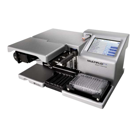
Priming trough inserts, for collecting fluid, are shown in this image. Plate Carrier Holds standard microplates for processing. Touch screen One of two ways to control the MultiFlo FX; the other way is LHC. Strip Washer An external module containing a syringe-pump dispenser and vacuum aspiration pump. -
Page 26: Peri-Pump Dispenser
4 | Chapter 1: Introduction Programmable dispense volumes, and a wide range of wash options, from gentle washing for cellular assays to vigorous washing for ELISA™. A “bottom washing” routine to lower the background absorbance and “crosswise” or secondary aspiration to reduce residual volumes. Supports Wash, Prime, Dispense, and Aspirate steps. -
Page 27: Liquid Handling Control™ (Lhc) Software
24-well plate: 8-channel dispense manifold (2 tubes/well). 48-well plate: 12-channel dispense manifold (2 tubes/well). Liquid Handling Control™ (LHC) Software BioTek’s Liquid Handling Control (LHC) software lets you control the instrument from your computer. You’ll enjoy the convenience of programming assay-specific ®... -
Page 28: Multiflo Fx Models
See RAD Tip Tracking on page 156. Access and preserve more reagent: single tube can handle minute quantities of reagent. cell monolayer is preserved MultiFlo FX Models Model Internal Peri-pump Strip Washer RAD Technology MFXW MFXP MFXPW MFXR MFXPR The Syringe and secondary Peri-pump dispensers are ordered separately. -
Page 29: Multiflo Fx Dispenser Comparison
MultiFlo FX Dispenser Comparison | 7 MultiFlo FX Dispenser Comparison Counting the washer as a potential dispenser, the MultiFlo FX offers three distinct dispensers. Here is a comparison of the devices: For precious reagents use the Peri-pump to preserve unused fluids. It has the shortest, most visible fluid path, and a Purge capability to reverse the fluid flow to recover fluid from the tubing. - Page 30 ‡ 0.5 µL dispensing is supported when using a 1 µL cassette. See Performance Specifications on page 21 ¥ Depending on wash manifold, BioTek recommends priming a dispenser with three times its dead volume to prepare it for accurate dispensing. §...
-
Page 31: Plate Types Table
MultiFlo FX Dispenser Comparison | 9 Plate Types Table Only the Peri-pump can process all plate types. Washer manifolds are named for plate types they process. Only the 32-tube Syringe dispenser manifolds and the Peri-pump can dispense to 1536-well plates. -
Page 32: Biostack Compatibility
If the Dispense Height is greater than Travel Height, the travel height is changed to match the dispense height. BioStack Compatibility The MultiFlo FX is compatible with BioTek’s BioStack Microplate Stacker. The BioStack can rapidly transfer microplates one-at-a-time to and from the instrument, and includes: Removable stacks (one input and one output). - Page 33 De-lidding and re-lidding capability with BioStack 4. If you have purchased the BioStack to operate with the MultiFlo FX, refer to the BioStack Operator’s Manual for instructions on configuring the MultiFlo FX to run with the BioStack.
-
Page 34: Package Contents
12 | Chapter 1: Introduction Package Contents Part numbers and package contents are subject to change and vary according to instrument model. Please contact BioTek Customer Care if you have any questions. Description Power cord (part numbers vary by country of use) -
Page 35: Optional Accessories
Optional Accessories | 13 Optional Accessories Part numbers and package contents are subject to change and vary according to instrument model. Please contact BioTek Customer Care if you have any questions. General Instrument Accessories Description BioTek liquid testing solutions for... -
Page 36: Syringe Dispenser Optional Accessories
14 | Chapter 1: Introduction Tubing Replacement Cassette Type Cassette Tips extension tubing kit* 5 µL plastic tips 7170011 7172059 7170008 7170021 5 µL stainless steel tips 7170014 7172128 5 µL plastic, large bore tips 7170024 7172039 10 µL plastic tips 7170010 7172059 7170007... -
Page 37: Strip Washer Optional Accessories
DMSO- & Acetonitrile-safe tubing sets (2 - 1/dispenser) 7183002 Special large-bore 8-tube manifold for 96-well plates 7180549S Strip Washer Optional Accessories Accessory Fluid Supply Kit 1263007 Waste Bottle and Tubing Kit 1263001 Waste Bottle with Sensor 4070545 BioTek Instruments, Inc. - Page 38 16 | Chapter 1: Introduction Accessory Spacer Block (substitute for Syringe manifolds) 1262038 Muffler 4073009 Thumb screws 01262 Vacuum Line Filter 48146 Tubing Bracket 1262066 Washer Manifold Kits Manifold Type Accessory Accessory Kit 1260013 96/384-Well Dispense Manifold 1262028 Aspirate Manifold 1262029 6-Well Accessory Kit...
- Page 39 Optional Accessories | 17 Accessory 384-well Flat Magnet 7103017 384-well Ring Magnet 7102215 96-well Flat Magnet 7103016 96-well Ring Magnet 7102216 BioTek Instruments, Inc.
-
Page 40: Physical Specifications
18 | Chapter 1: Introduction Physical Specifications Labware Microplates 96-well, 384-well, and 1536-well that comply with ANSI/SLAS microplate standards 1-2004, 2-2004, 3-2004, and 4-2004. 96-well standard, half-height, deep; 384-well standard, deep, PCR; 1536- well standard and flanged. The Peri-pump and plate-type specific washer and syringe manifolds also support 6- (Corning®... - Page 41 1 x 8-channel autoclavable manifold (4 tubes/well) with replaceable stainless steel tubes to process 6-well plates. Tubes are angled 7 degrees to minimize turbulence in the wells. 12-Well 1 x 9-channel autoclavable manifold (3 tubes/well) with replaceable BioTek Instruments, Inc.
- Page 42 20 | Chapter 1: Introduction Manifold Type stainless steel tubes to process 12-well plates. Tubes are angled 7 degrees to minimize turbulence in the wells. 24-Well 1 x 8-channel autoclavable manifold (2 tubes/well) with replaceable stainless steel tubes to process 24-well plates. Tubes are angled 7 degrees to minimize turbulence in the wells.
-
Page 43: Performance Specifications
(chute) with 5 µL tubing for volumes that are 8 times the full unit increments for the cassette, e.g. valid at 40, 80, 160, ... 30,000 µL: ± 4% when volume is 40 µL/well ± 2% when volume is ≥80 µL/well. BioTek Instruments, Inc. -
Page 44: Syringe Dispensers
22 | Chapter 1: Introduction Cassette Expected Lifetime Cassette Types Cassette Life Total Volume 1 µL 1000 384-well plates @ 5 µL/well 2,000 mL 5 µL 1000 96-well plates @ 50 µL/well 5,000 mL 10 µL 1000 96-well plates @ 100 µL/well 10,000 mL With strict adherence to best practices and maintenance recommendations, this is the typical longevity of the dispense cassettes. -
Page 45: Strip Washer
Well aspirate height adjustment should be optimized for the plate prior to testing.) Washer Manifold Volume (µL/well) Travel Rate Residual Volume (µL/well) 6-well 5560 0 CW 12-well 2240 0 CW 24-well 1120 0 CW 48-well 0 CW BioTek Instruments, Inc. - Page 46 24 | Chapter 1: Introduction Dispense Precision Refer to the values below for washer dispense precision when measured in full plates with the specified volume of deionized water with 0.1% Tween 20 and FD&C#1 blue dye solution and read at 630 nm/405 nm. Plate Type Performance Volume (µL/well)
-
Page 47: Space Requirements
(W), depth (D) and height Physical Specifications on page 18 (H) of the base unit of the MultiFlo FX without an external Peri-pump, Syringe dispenser, or Washer installed. Likewise, the space required for the bottles, tubing and power cables is omitted. -
Page 48: Biotek's Customer Resource Center
BioStack Operator's Manual. BioTek's Customer Resource Center BioTek's Customer Resource Center (CRC) continues our tradition of superior service and support. After an easy registration process, you can access lots of useful information about your BioTek microplate instrumentation and software. On... -
Page 49: Installation
Install the Syringe Dispenser Component Install Software/Connect to Computer Connect Power Cable Define Instrument Settings Verify Performance Repacking the MultiFlo FX Install the Shipping Hardware Repacking the Secondary Peri-pump MultiFlo FX Repacking Repacking the Syringe Dispenser Repacking the Strip Washer... -
Page 50: Unpack And Inspect The Instrument
Unpack and Inspect the Instrument Important: Save all packaging materials. If you need to ship the instrument or accessories to BioTek for repair or replacement, you must use the original packaging. Using other forms of commercially available packaging is not recommended and can void the warranty. -
Page 51: Install The Waste Tubing
Philips head screwdriver (small) Waste tubing: 4' provided (PN 7213010) Possibly scissors or knife to cut tubing to desired length Side bracket provided Waste vessel: to capture discarded fluid To install the tubing: Install Side Bracket for Waste Tubing BioTek Instruments, Inc. - Page 52 30 | Chapter 2: Installation 1. Turn instrument onto its back to access its underside. 2. Remove the two screws in the lower left corner. You will use them to install the bracket. 3. Align the side bracket with the screw holes so its hook opens towards you and use the screws to install the bracket.
-
Page 53: Remove The Shipping Hardware
Two shipping brackets (and a rubber band when a Peri-pump is included) protect the MultiFlo FX during shipping. After installing the waste tubing for the priming trough, place it upright on a level work surface to remove the shipping hardware. - Page 54 32 | Chapter 2: Installation without a washer or RAD technology: For these MultiFlo FX models: MFXP First remove the plate carrier shipping bracket and then remove the dispense arm bracket. Reverse this order when reinstalling the brackets (before shipping): put the...
- Page 55 Remove the Shipping Hardware | 33 Dispense-arm bracket for MultiFlo FX without a washer or RAD technology 4. Insert the brackets into their respective slots on the back of the instrument, in lower right corner. Slide the plate-carrier bracket's longest arm into the slot and use the Allen wrench to screw it in place.
-
Page 56: Set Up The Strip Washer
34 | Chapter 2: Installation Set up the Strip Washer Perform these steps: Attach washer module and connect its cable on the facing page, Install the tubing bracket on page Install the Fluid Supply on page Install the Waste Bottle on page Install the muffler on page Install Washer Manifolds on page Strip Washer accessories... -
Page 57: Attach Washer Module And Connect Its Cable
Attach washer module and connect its cable The MultiFlo FX's optional strip washer is positioned on posts and attached to the back of the instrument. A bracket holds the fluid supply and waste tubing, keeping BioTek Instruments, Inc. - Page 58 36 | Chapter 2: Installation the tubing secure and away from moving parts. You need a Philips screwdriver. back panel 1. First, remove the screws and washers that will attach the washer to the back panel. 2. Align the slots on the side of the washer module with the two posts near the base.
-
Page 59: Install The Tubing Bracket
1. First, remove the two screws you will use to attach the bracket. Refer to the photo below to locate the screws on the back of the instrument. 2. Align the bracket to the holes and use the screws to attach it. BioTek Instruments, Inc. -
Page 60: Install The Fluid Supply
38 | Chapter 2: Installation The tubing bracket is designed to snugly hold the check valves of the fluid supply tubing and the waste tubing's rigid valve. Install the Fluid Supply The strip washer's fluid supply system (PN 1263007) uses a two-liter plastic supply vessel and two tubes with check valves, powered by a non-autoclavable... -
Page 61: Install The Waste Bottle
(inside the washer module) and the aspirate manifold to perform this function. An inline vacuum filter (not shown) is optional but strongly recommended because (1) the filter prevents waste material aerosols from being released into the air, and BioTek Instruments, Inc. - Page 62 40 | Chapter 2: Installation (2) the filter serves as a temporary fluid barrier in the event that the waste bottle is allowed to overfill. (The filter part number is 48146.) An optional Waste Sensor bottle, PN 4070545, alerts users to the need to empty the waste container, preventing overflow problems.
-
Page 63: Install The Muffler
And, the washer dispense manifold must be installed before the aspirate manifold is installed. 1. Turn off the MultiFlo FX, if necessary. Install the Fluid Supply on page 38 2. - Page 64 42 | Chapter 2: Installation 3. Connect the waste vessel tubing to the aspirate manifold. 4. Lower the aspirate arm to gain access to the dispense arm, if necessary, i.e. move it out of the way. 5. First, install either the Syringe dispenser manifolds or the spacer block on the dispense arm:...
- Page 65 Spacer block " ," if applicable. To remove the washer manifolds: Reverse the order of the installation steps, i.e. first remove the aspirate manifold: press the release tab. Then, remove the dispense manifolds. BioTek Instruments, Inc.
-
Page 66: Set Up The Peri-Pump Dispenser
Optionally, if you are installing an external (or secondary) Peri-pump, install the cover panel provided to conceal the primary Peri-pump. Install the cover panel using the two hex screws and the Allen wrench shipped with the MultiFlo FX. MultiFlo™ FX Multi-Mode Dispenser... - Page 67 Set Up the Peri-pump Dispenser | 45 MultiFlo FX with closed Peri-pump cover panel BioTek Instruments, Inc.
-
Page 68: Install The Secondary Peri-Pump
Install the Secondary Peri-Pump An optional secondary or external Peri-pump dispenser is available for the MultiFlo FX. It ships as a kit with its own accessories and it is required for RAD™ technology. Inspect and unpack the shipping container and follow these installation instructions if applicable. - Page 69 3 - additional dispense cassette bracket 4 - interface cable to connect unit to the instrument 5 - MultiFlo FX Only: extra stainless-steel bracket to replace #2 Also note the screwdriver, Allen (hex) wrench, and shoulder screw shipped with the accessories.
- Page 70 48 | Chapter 2: Installation 1. First, remove the support bracket stored on the back of the instrument. It will be used to secure the dispenser on top of the instrument. Remove the two screws holding the bracket in place. 2.
- Page 71 4. Use the four screws to secure the bracket over the existing bracket. Place and partially tighten the screws until all four are in place, then tighten all the screws. BioTek Instruments, Inc.
- Page 72 50 | Chapter 2: Installation Install cable to connect the dispenser: 1. On the back of the instrument, connect the interface cable to the Peri-pump Dispenser port on the back of the instrument and to the port on the back of the Peri-pump unit.
-
Page 73: Install Rad Technology Components
Install RAD Dispense Head on page 53 Install RAD Technology Cassette on page 58 Install the Tubing Bracket and RAD Module First, install the tubing bracket and then attach the small RAD module with a serial port to the bracket. BioTek Instruments, Inc. -
Page 74: Install The Tubing Bracket
52 | Chapter 2: Installation Install the tubing bracket A stainless steel bracket to keep the tubing away from moving devices is provided with the washer and RAD models. Attach the bracket to the back of the instrument: near the top, center of the instrument, slightly left of the aluminum mounting plate as you face the back panel. -
Page 75: Install Rad Dispense Head
RAD module (installed in earlier step). 1. Align the two pins on the dispense head with the two holes on the Release Tab RAD arm, and press the (on the front of the arm) to install the dispense head. BioTek Instruments, Inc. -
Page 76: Dispense Cassette Diagram
54 | Chapter 2: Installation 2. Plug the ribbon cable on the dispense head into the RAD module (installed on the tubing bracket). Next, install the RAD cassette: Install RAD Technology Cassette on page 58 Dispense Cassette Diagram 1 - Tip Holder 2 - Center Holder 3 - Tube Tensioner 4 - Tubing Organizer... - Page 77 5. Tip Guard: Remove the tip guard before installing the cassette. The tip guard protects the tips during shipping. It is not a permanent part of the cassette. The RAD single-tube cassette also ships with a tip guard. BioTek Instruments, Inc.
-
Page 78: Install The Dispense Cassette
(on the right side of the caution symbol on the pump) and use your left hand to lift the stainless steel plate up and out. The BioTek logo on the Tip Holder faces the Peri-pump. The logo on the Center Holder faces down, away from the pump. - Page 79 1. Slide the into the Tip Holder dispense arm. The Tip Holder’s front plate with the BioTek logo or steel plate faces the pump. Make sure the tip holder is level and snapped into place. Two Peri-pumps: use left bracket for Primary, right bracket for Secondary.
-
Page 80: Install Rad Technology Cassette
58 | Chapter 2: Installation Install RAD Technology Cassette RAD technology's single-tube and 8-to-1 bulk dispensing cassettes are installed like standard cassettes with one difference, the tip holder is installed on the dedicated RAD dispense head. Install the RAD cassettes on the external or secondary Peri- pump ! They are not designed for use on an internal Peri-pump. -
Page 81: Prime Trough Inserts
Install RAD Technology Components | 59 Prime Trough Inserts The MultiFlo FX ships with special reservoirs that fit into the dispensers’ priming trough to capture expensive reagent after priming, rather than discarding it. Three types of Prime Trough Inserts may be provided:... -
Page 82: Peri-Pump Reservoir Holder
60 | Chapter 2: Installation Peri-pump Reservoir Holder MultiFlo FX models with a Peri-pump dispenser include the convenient Peri- pump reservoir holder (PN 7210509). The simple bracket clips onto the front of the Peri-pump to hold a variety of vessels. -
Page 83: Shorten The Dispense Cassette Tubing
Install RAD Technology Components | 61 Shorten the Dispense Cassette Tubing Shortening the fluid path reduces the dead volume when dispensing, which helps preserve expensive reagents. BioTek offers the Peri-pump Reservoir Holder on the as an accessory to the Peri-pump dispenser for this purpose. The previous page cassette tubing can be shortened by as much as 12 inches (30.48 cm) when using the... -
Page 84: Install The Syringe Dispenser Component
62 | Chapter 2: Installation Install the Syringe Dispenser Component The Syringe dispenser is an optional component and ships separately. Inspect and unpack the shipping container. Skip this part of the installation process if it is not applicable. 1 - Syringe Dispenser module (autoclavable) 2 - interface cable 3 - tubing bracket 4 - priming trough inserts... -
Page 85: Syringe Dispenser Placement Options
Follow the installation instructions for your preferred placement of the dispenser: Install the Syringe Dispenser on Top on page 65 BioTek Instruments, Inc. -
Page 86: Install The Syringe Dispenser On Back Shelf
Install the Syringe Dispenser on Back Shelf Follow these instructions to install the dual Syringe Dispenser module on a shelf attached to the back of the MultiFlo FX or on top of the washer module. MultiFlo FX Only: The washer module functions as a shelf for the syringe dispenser: skip this step, and use the washer as a shelf, if applicable. -
Page 87: Install The Syringe Dispenser On Top
7. Put the syringe pump module on the shelf or the washer module. 8. Plug the serial cable into the back panel of the MultiFlo FX in the port labeled . Plug the other end into the syringe pump unit. - Page 88 Syringe dispenser. Syringe dispenser on top of secondary Peri-pump The MultiFlo FX ships with a support bracket attached to the back of the instrument. The support bracket has foot holds for the Syringe dispenser. The bracket's flexible design supports either one or two devices, the secondary Peri- pump and the Syringe dispenser, alone or in combination.
- Page 89 4. Plug the 26-pin high-density cable into the back panel of the MultiFlo FX in the port labeled . Plug the other end into the syringe Syringe Pump Dispenser pump unit.
-
Page 90: Install Tubing And Manifolds For Syringe Dispenser
68 | Chapter 2: Installation Install Tubing and Manifolds for Syringe Dispenser For each dispense pump, a set of two tubes with check valves and two supply bottles are provided. The 32-tube dispense manifolds also ship with an optional inline filter. The supply bottles have Luer fittings. - Page 91 A slides on first, then B. Special procedure required for magnetic bead assays! A magnet holds the two manifolds in place on the dispense arm. You can remove the magnet when necessary for certain assays (as described on page 151). BioTek Instruments, Inc.
-
Page 92: Syringe Dispenser Check Valves
70 | Chapter 2: Installation You can install the tubing bracket: on the front near the Peri-pump on the back next to shelf or share washer/RAD bracket 6. Make sure the manifold has enough slack in the tubing to move down to the priming trough and then press the tubing into the tubing bracket to keep the tubing out-of-the-way. -
Page 93: Install Inline Filter For 32-Tube Dispensers
3. Slide the filter’s nozzle ends into the two ends of the tubing, reconnecting it. Install Software/Connect to Computer If you purchased BioTek's Liquid Handling Control™ (LHC) Software to control the MultiFlo FX using your personal computer (PC), please refer to the LHC Installation Guide for complete installation and setup instructions. BioTek Instruments, Inc. -
Page 94: Connect To Host Computer
They cannot be used simultaneously. You can use USB to connect the MultiFlo FX to the computer or the RS232 serial port to connect to a BioStack or similar robotic device. But you cannot use both ports simultaneously, i.e. -
Page 95: Define Instrument Settings
Define Instrument Settings | 73 The MultiFlo FX supports voltage in the range of 100-240 V~ at 50-60 Hz. 1. Connect the power cable to the power supply. 2. Plug the power supply cable into the power socket in the side panel of the MultiFlo FX. -
Page 96: Update The Instrument To Use The Syringe Dispenser
2. Turn on the instrument, launch press Instrument. the LHC and make sure it is communicating with the 3. Select Syringe and specify the MultiFlo FX (define the correct installed manifold type. COM port). 4. Under Calibration Data from, 3. Select Tools>Instrument... -
Page 97: Change The Syringe Dispenser Manifold
Tools> Instrument Utilities> Syringe Dispenser Touch screen: Select Instrument> Syringe> Manifold 2. Choose the option that represents the installed manifold. Look at the top of the manifold to identify its type, which is engraved on the top: BioTek Instruments, Inc. -
Page 98: Change The Cassette Type Setting
158) to automatically update the instrument's Cassette Type setting when you run a protocol. For advanced users with well organized procedures, the MultiFlo FX provides the ability to change the cassette type setting on-the-fly. It uses the "Require a specific cassette"... -
Page 99: Setting The Time And Date
Define Instrument Settings | 77 Setting the Time and Date Set the time and date to permit the MultiFlo FX to record "last run" and "last modified" data for each protocol. Only the U.S. date format is available (MM/DD/YYYY). An internal battery keeps the time and date valid when the instrument is turned off. - Page 100 78 | Chapter 2: Installation 3. Highly Recommended: select the , fill in the text fields, and add any Plate Type steps that you want all new protocols to include. Click and assign a unique name, e.g. Template.LHC. Save 5. Select Tools>Preferences>New Protocol Select the button for Protocol selected below to use as a template...
-
Page 101: Verify Performance
Verify Performance Before using the MultiFlo FX for the first time, verify that it is operating properly. When using the LHC, make sure the MultiFlo FX is connected to the PC and both are powered up. When running standalone, turn on the MultiFlo FX. -
Page 102: Verify The Peri-Pump Dispenser
1. Fill the Peri-pump’s supply bottle with approximately one liter of deionized water. Touch screen 1. Select 1. Select at the Home screen. File > Open Quick 2. Open the MultiFlo FX and 2. Select and set the Device Prime Maintenance Protocols folders, and Device to the Peri-pump then open P-xUL_CASS_RINSE.LHC... -
Page 103: Verify The Washer Component
Verify Performance | 81 If leaks were detected, tighten all tube fittings and re-run the program. If leaks are still detected, contact BioTek’s Technical Assistance Center. Verify the Washer Component 1. Fill the washer’s supply bottle with approximately one liter of deionized water. -
Page 104: Repacking The Multiflo Fx
See Decontamination on page 205. If the original packing materials have been damaged or lost, contact BioTek to order replacements. Part Numbers: 7213006 for the main instrument, 1263003 for the washer, and 7213008 for the secondary Peri-pump and 1263004 for other accessories, if applicable. -
Page 105: Install The Shipping Hardware
Install the Shipping Hardware | 83 Install the Shipping Hardware Install the two shipping brackets to protect the MultiFlo FX during shipping. You will need: Allen (or hex) wrench provided with the instrument. The shipping brackets removed from their storage slots on the back of the instrument. - Page 106 84 | Chapter 2: Installation For these MultiFlo FX models: MFXP First remove the plate carrier shipping bracket and then remove the dispense arm bracket. Reverse this order when reinstalling the brackets (before shipping): put the dispense arm bracket on the post first.
-
Page 107: Repacking The Secondary Peri-Pump
BioTek’s Technical Assistance Center for guidance. Multiple accessory modules are available for the MultiFlo FX. Foam blocks are used as space fillers in the packing containers when the modules, like the secondary Peri-pump, are not shipped. -
Page 108: Multiflo Fx Repacking
2. Repack the cardboard and foam shipping materials to secure the items in place. 3. Tape the box closed. This box will fit into the box with the instrument. MultiFlo FX Repacking 1. Reverse the steps described to Remove the Shipping Hardware. - Page 109 MultiFlo FX Repacking | 87 3. With the shipping hardware installed, sit the instrument in the foam edged box bottom. 4. Place the end caps on either side and put all items inside the interior shipping box. 5. Place accessory boxes inside interior box.
- Page 110 88 | Chapter 2: Installation 7. Put the eight foam corner blocks on the interior box and put it inside the outer box. 8. Tape the outer box closed. 9. Write "RMA" in large, clear letters on the outer box. 10.
-
Page 111: Repacking The Syringe Dispenser
After preparing the instrument for shipping, and reversing the installation steps, pack the Syringe dispenser as shown here: Fill the foam tray with the Syringe dispenser accessories and place the tray on top of the inner foam box containing the pump and supply bottles. BioTek Instruments, Inc. -
Page 112: Repacking The Strip Washer
The instrument’s packaging design is subject to change over time. If the instructions in this section do not appear to apply to the packaging materials you are using, please contact BioTek’s Technical Assistance Center for guidance. Uninstall the strip washer: 1. -
Page 113: Operation
Chapter 3 Operation This chapter provides instructions for controlling the MultiFlo Touch Screen Basics Optimize Performance Create or Modify a Protocol Protocol Parameters Tables Wash Parameters Table Predefined Protocols Listing Predefined Sample Protocols Operating with the BioStack Advanced Plate Sequencing with the BioStack Plate Types and Processing Patterns Handling Special Plates and Mini-tubes Dispense Processing Patterns... -
Page 114: Touch Screen Basics
92 | Chapter 3: Operation Touch Screen Basics Home screen Fast, Light Touch: a light, quick tap on the screen produces the best results. Use your fingertip or a pointing device like a pen tip. The touch screen does not support gestures, like swiping and zooming, that are common to smart phones. -
Page 115: Quick Prime
Home: Press the home button to return to the Home screen at any time. Previous: Press the previous button to go to the previous screen. Help: To learn more about a screen, press its Help button. Green buttons make the MultiFlo FX perform. Quick Prime At the Home screen select Quick>Device Prime Priming removes air bubbles from the tubing, ensuring optimal performance. -
Page 116: Quick Dispense
94 | Chapter 3: Operation Note: the washer aspirates fluid during the prime step, but it does not fully evacuate the priming trough insert. Quick Dispense Quick Dispense uses default values for all parameters except those available for modification. To alter the flow rate, dispense height, and other parameters, you must define a protocol. -
Page 117: Quick Wash
Step. Add protocols to the Home screen The MultiFlo FX puts all saved protocols on the Home screen for easy retrieval. Create and save a protocol to add it to the Home screen listing. Create or Modify a Protocol on page 102 Remove protocols from the Home screen All saved protocols appear on the Home screen. -
Page 118: Get Protocols From A Memory Stick - Usb Drive
Important: Put the protocols you want to transfer to the washer in a folder called Protocols. The MultiFlo FX expects to find a Protocols folder on the memory stick. You can exchange MultiFlo FX protocols with other users, copy protocols from one washer to another, or obtain sample protocols from BioTek's website using a USB stick:... - Page 119 Touch Screen Basics | 97 Ongoing operation: Check your instrument setup for any unintended changes: are the serial cables properly connected to the back of the MultiFlo FX? BioTek Instruments, Inc.
-
Page 120: Optimize Performance
See Recommended prime volumes for the Syringe dispensers on page 101 See Recommended prime volumes for the Strip Washer on the facing page Best Practices for all MultiFlo FX Devices Fill the supply bottles with sufficient fluid. Make sure the bottles, solutions, and tubing are clean and do not contain any particles or mold. -
Page 121: Recommended Prime Volumes For The Strip Washer
However, a primary advantage of the Peri-pump dispenser is its entirely visible fluid path. This allows you to prime the tubing until all visible signs of air bubbles are dissipated. BioTek Instruments, Inc. - Page 122 150 µL 5 µL 530 µL 10 µL 920 µL Use BioTek's Peri-pump Reservoir Holder on page 60 Shorten the Dispense Cassette Tubing on page 61 to significantly reduce the dead volume to preserve expensive reagents. At the start of the day: Prime the tubing to prepare for a dispense run.
-
Page 123: Recommended Prime Volumes For The Syringe Dispensers
5 µL cassette = 7 seconds 10 µL cassette = 10 seconds. The MultiFlo FX will prime for this duration each time, which dispenses fluid approximately equal to the dead volume for the cassette type. Recommended prime volumes for the Syringe dispensers... -
Page 124: Create Or Modify A Protocol
102 | Chapter 3: Operation immediately after each aspiration in a wash cycle and/or after the final aspiration step. Secondary aspiration is also called Crosswise aspiration because it is typically performed in a different location within the well. Reposition the tubes by defining different X-, Y-, and/or Z-axis positions when enabling the secondary aspiration for the most effective evacuation of the wells. -
Page 125: Protocol Parameters Tables
Especially when creating complex BioStack protocols, use the Validate button to check the order of the protocol steps. Protocol Parameters Tables For Wash step parameters see Wash Parameters Table on page 108 Peri-pump Parameters BioTek Instruments, Inc. - Page 126 104 | Chapter 3: Operation Default Step Option Description/Values range values Prime To remove air from the tubing. Volume: 1-3000 µL Duration: 1-300 seconds Dispense Volume The per-well volume to dispense: Up to 1 µL cassette = 1 - 50 µL and 0.5 µL (HLF-D) for some 30,000 µL models* per well is...
- Page 127 Uninstall the dispense cassette, if it is not required by a protocol, to prevent collisions when trying to position the Syringe or Wash dispenser as close as possible to the wells. And/or, consider increasing the Plate Clearance Height setting to increase the travel height. BioTek Instruments, Inc.
- Page 128 106 | Chapter 3: Operation Syringe Dispenser Parameters Default Step Option Description/Values range values Prime Flow rate: 1-5 (See dispense step description below) Volume: 80-8000 µL. To remove air from the tubing. 5000 Syringe: A or B Cycles: Number of prime cycles to perform Pump 0-5000 msec.
- Page 129 50-59 60-79 80-3000 1000 384-well plate Volume Rate µL/sec/well (µL) 5 -9 10-24 25-29 30-39 40-1500 Note: For 16-channel syringes the µL/sec/well rate accounts for 2 tubes/well when addressing 96-well plates and one tube/well for 384-well plates. BioTek Instruments, Inc.
-
Page 130: Wash Parameters Table
108 | Chapter 3: Operation 1536-well plate Rate Volume (µL) 3-3000 The 32-tube manifold flow rates do not have minimum volumes. The µL/sec/well for each type of manifold, Small Bore (SB) and Large Bore (LB), is shown: The default rate is 3. Low-density-plate manifolds Like the standard manifolds described above, for these plate-type-specific manifolds the flow rate is defined as... - Page 131 For cell-based assays, use rate 1 or 2 for gentle washing. For normal dispensing, the range is 3-11, 3 is slowest and 11 is fastest. Volume µL/well dispensed: See Washer Flow Rate on page Plate type 111. specific BioTek Instruments, Inc.
- Page 132 110 | Chapter 3: Operation Default Option Description/Values range values Positioning X- and Y- horizontal axes, Z- height (vertical) axis Z = 336 for can be adjusted to improve performance. See 96-well plate Axis: Default Dispense and Aspirate Heights. X & Y = 0 Vacuum Delay Suspends the vacuum pump until a certain volume is dispensed.
-
Page 133: Washer Flow Rates
Rate 1 is designed for cell wash assays, causing the least disturbance in the wells. Rate µL/tube/second Cell Wash 1 Cell Wash 2 Default 5 Note that flow rates are per tube. Depending on the wash manifold and plate type there may be multiple tubes in a well. BioTek Instruments, Inc. - Page 134 112 | Chapter 3: Operation Minimum Dispense Volumes (µL/well) per Manifold Rate 96/384-well 6-well 12-well 24-well 48-well 1 CW Aspirate Travel Rates Rate mm/sec 0 CW for 6-, 12-, 24-well plates 4.1 +1 Slowest 1 CW 5.0 +1 2 CW 7.3 +1 Default rate 3 CW...
-
Page 135: Pre-Dispense
Use the Pre-dispense feature to quickly prime the tubes or tips between runs. When a Pre-dispense is enabled, the MultiFlo FX moves the plate to the home position to allow the manifold to dispense into the priming trough. -
Page 136: Minimum Prime Volumes For The Strip Washer
114 | Chapter 3: Operation Minimum Prime Volumes for the Strip Washer Flow rate: Wash Manifold Type 6-Well 12-Well 24-Well 48-Well 96/384-Well Bottom Wash Bottom washing adds an initial dispense/aspirate sequence to the protocol. Fluid is simultaneously dispensed and aspirated to create cleaning turbulence (at the specified height). -
Page 137: Change The Plate Type
Rename a protocol There are two ways to rename a protocol, edit the name or make a copy and rename the copy. The MultiFlo FX behaves like Windows' Save As function, creating a copy of the protocol file when it is renamed. -
Page 138: Shake/Soak Step Parameters
116 | Chapter 3: Operation Shake/Soak Step Parameters Select the action to perform: Move carrier to home position first. Regardless of selection, the plate carrier is moved home during a stand-alone shake step and when the total time of the shake and soak durations exceeds 1 minute. The vacuum pump is turned off in this scenario. -
Page 139: Delay The Protocol
The operator can override the delay at any time by clicking the button. Otherwise, the protocol will not resume until Continue the specified time has expired. The maximum length of a fixed delay is 23:59:59 (23 hours, 59 minutes, 59 seconds). BioTek Instruments, Inc. -
Page 140: Timer Activated Delay
BioStack loop. To remove the delay from the protocol, you must delete both steps. Examples: These examples show protocols for an EL406 Washer Dispenser, but the same principles apply to the MultiFlo FX. Simple Delay To use the timer successfully, you must first determine the approximate duration of your protocol steps. - Page 141 250 µL from the Peri-pump and then, after 1 hour, the plate is washed. The protocol will fill each plate in the rack, restack the plates, and then wash each plate 1 hour after it was filled. The dispense and wash activities are each BioTek Instruments, Inc.
-
Page 142: Run: Running Predefined Protocols
The LHC stores the COM port value in the protocol file. With the MultiFlo FX connected to and communicating with the host computer (i.e. make sure the instrument is turned on and not busy):... -
Page 143: Predefined Protocols Listing
Predefined Protocols Listing | 121 Click the button, locate the folder and click Open MultiFlo FX Open 2. Open the or other folder and select the desired protocol. Maintenance Change the COM port if necessary: click and enter the correct value Port or select from the drop-down list. -
Page 144: Predefined Sample Protocols
122 | Chapter 3: Operation Periodic Maintenance S-Decontaminate Includes prompts for first running disinfectant and later running water through the system. It can be easily modified to suit any major cleaning effort. The A or B suffix identifies the syringe the protocol is designed for. - Page 145 50 µL/well Peri-pump dispense using a single-tube RAD cassette to partially fill a 384-well plate, hit-picking wells in a pattern that represents the BioTek logo. Begins with two 10 µL/tube pre-dispenses. P_RAD 8Tube- 1120 µL/well Peri-pump dispense using the 8-to-1 RAD cassette to partially fill a 24-well plate, dispensing to each corner well and 4 wells in the center.
-
Page 146: Operating With The Biostack
(not at runtime). LHC Control: LHC users: connect both the BioStack and the MultiFlo FX to the computer and control them with the LHC. Design protocols that integrate BioStack controls with MultiFlo FX steps. LHC protocols must contain a BioStack loop. -
Page 147: Use The Biostack
They cannot be used simultaneously. You can use USB to connect the MultiFlo FX to the computer or the RS232 serial port to connect to a BioStack or similar robotic device. But you cannot use both ports simultaneously, i.e. - Page 148 126 | Chapter 3: Operation 1. Highlight a step or the <end of steps> placeholder and press and then . This adds a BioStack start step, BioStack delivers and an end step, BioStack returns plate. The end step is highlighted. 2.
-
Page 149: Re-Stack Plates In The Biostack
Typically, the BioStack will work perfectly using one of the Plate Lid Definition files provided by BioTek. Review the list to find one that matches your lids. If, however, you do not find a match or you experience problems when transferring plates or lids, create your own files. -
Page 150: About The Nth Plate Step
The MultiFlo FX identifies the special plate or plates (that we call Nth plate) by counting the number of plates that have been processed before it. -
Page 151: Advanced Plate Sequencing With The Biostack
BioStack block. When the first step is an Nth Plate block, the MultiFlo FX can evaluate it to determine which plates will be handled in a special way. Any steps that precede an Nth Plate block will be performed on all plates, including the Nth designated plates. - Page 152 130 | Chapter 3: Operation plates to stagger the dilutions, as shown in the table below. Similarly, three BioStack step blocks can result in a stack of plates sorted into dilution groups. Using a series of Nth Plate or BioStack step blocks we can dispense 100 µL to plates in the first pass, 200 µL to plates in the second pass, 300 µL in the third pass.
- Page 153 5 cycles, 5 plates with 4 cycles, 5 plates with 3 cycles, and 5 plates with 2 cycles. The plates in the BioStack's output stack will be sorted this way: Plates # Wash Cycles BioTek Instruments, Inc.
- Page 154 132 | Chapter 3: Operation Alternatively, Use Nth Plate steps to create mixed groups of plates, where each group contains a plate with 5 wash cycles, a plate with 4 wash cycles, a plate with 3 wash cycles, and so on. Serial Dilutions Examples Nth Plate: To generate mixed groups of dilutions in the stack of plates, as depicted in the table below, three Nth Plate steps are used.
-
Page 155: Plate Types And Processing Patterns
Plate Types and Processing Patterns Depending on the type of hardware installed on the instrument, e.g. manifold type, the MultiFlo FX can process several plate types. The default parameters for wash and dispense steps represent the optimal positioning of the hardware for the plate type. -
Page 156: Handling Special Plates And Mini-Tubes
To achieve the best dispense performance when processing 1536-well flanged plates, the MultiFlo FX's default protocol settings specify a low dispense height to position the dispense tubes as close as possible to the wells. When the dispense arm holds multiple dispense manifolds, the manifolds not addressing the wells can collide with the plate flanges during a dispense. - Page 157 6-, 12-, 24-, and 48-Well Plates When addressing these plates with the Peri-pump, BioTek recommends experimenting with different dispense-tube-to-well configurations. For some plates, multiple tubes can dispense to a single well. Conversely, dispense tubes can (and sometimes, must) be removed from the supply vessel or from the cassette to prevent them from missing the wells.
-
Page 158: Special Plate Carrier For Mini-Tubes
Replace Peri-pump Dispense Cassette Tubing on page 210. Special Plate Carrier for Mini-tubes An optional accessory for the MultiFlo FX, a special plate carrier is needed to support certain special vessels, like a box of mini- tubes. (PN 7212042) -
Page 159: Mini-Tube Racks
Note: Position adjustments in the Y-axis are prohibited with the special plate carrier for mini-tubes. Dispensing to Mini-Tubes Unlike most dispensing with the MultiFlo FX, the fluid stream does not hit the center of the well or tube when dispensing to the mini-tubes using the special plate carrier. -
Page 160: Dispense Processing Patterns
138 | Chapter 3: Operation Dispense Processing Patterns When dispensing to high-density plates, 384- and 1536-well, 8-channel dispensers, like the (non-RAD) Peri-pump cassettes and certain Syringe dispensers, employ a dispensing pattern that permits filling only a portion of the plate, skipping some sections. -
Page 161: 8-Channel Dispenser Dispense Pattern
With Advanced Dispense Options, you can skip certain rows and columns. The MultiFlo FX let's you specify which columns to skip during a dispense step. 384-Well Plate Rows: You can skip one of the two "rows" sections: When an 8-channel dispenser addresses a 384-well plate, it first dispenses to odd numbered rows, and then dispenses to even numbered rows. -
Page 162: Dispense Pattern With Both Syringes
140 | Chapter 3: Operation When an 8-channel dispenser addresses a 1536-well plate, it first dispenses to rows 1, 5, 9, 13, 17, 21, and 25. The next section of rows dispensed to includes 2, 6, 10, 14, 18, 22, 26, and 30. And so on, creating 4 sections of rows. Dispense Pattern with Both Syringes When "Both"... -
Page 163: Washer Operation
Washer Operation | 141 Washer Operation About the MultiFlo FX Wash Step Minimally, a wash step includes an aspirate step followed by a dispense step. This is a wash cycle. The default definition of a wash step includes 3 cycles, followed by a final aspiration to evacuate the wells. -
Page 164: Cell Wash
When the Flow Rate is set to 1 or 2, the MultiFlo FX dispenses fluid to the wells slowly enough to avoid damaging the cells. -
Page 165: Cell Wash Strategies
Advanced Options link and enable the until sufficient fluid has been dispensed. For small dispense volumes, BioTek recommends setting the delay volume to equal your dispense volume. Reposition the dispense tubes to aim fluid at the side of the wells to reduce turbulence and change the aspirate height to increase the amount of residual fluid left in the well to protect the cell layer. - Page 166 For cell wash assays, specify at least 10 µL/well. For small dispense volumes or to disable aspiration for the entire dispense duration, set the vacuum-on volume to equal your dispense volume. Refer also to application notes on the BioTek web site for more information (www.biotek.com).
-
Page 167: Biomagnetic Separation - Magnetic Bead Assays
The magnet induces magnetic beads to settle at the bottom of the wells to help retain them during a wash protocol’s aspirate cycle. The MultiFlo FX supports standard microplates and these magnets available for purchase from BioTek:... -
Page 168: Perform Magnetic Bead Assays
146 | Chapter 3: Operation The magnet should be stored in a cool, dry environment and should be cleaned with a damp cloth and mild detergent when exposed to harsh solvents. Do not autoclave. To install the magnet in the proper orientation: Flat magnet: place in the plate carrier adapter so the text on the side of the magnet is readable;... -
Page 169: Optimize Magnetic Bead Protocols
The 96- and 384-well magnets are structured differently. Their force fields traverse the magnet in opposite directions. Magnetic beads in the wells will be drawn to the center. For the best bead retention, reposition the aspirate tubes in the proper axis: BioTek Instruments, Inc. -
Page 170: Ring Magnets
148 | Chapter 3: Operation 96-well Flat Magnet PN 7103016 The magnetic force (approx. 6800 Gauss) is distributed in a horizontal pattern, row-wise, across the plate. Magnetic beads are pulled to the center, across the well in flat-bottom plates and to the button in round-bottom plates. -
Page 171: How To Determine The Magnet Adapter Height Offset
3. Remove the plate, and measure it alone. 4. Subtract the stand-alone plate measurement from the measurement value of the combined elements. This is the value to use. Examples In our testing we found these offset values to be effective: BioTek Instruments, Inc. -
Page 172: Magnet Height Offset
For the best results, measure the height of the plate you are using with the magnet. BioTek has determined that Nunc flat bottom plates are about 3 mm taller than a similar Corning plate, for example. -
Page 173: Special Procedure For Magnetic Bead Assays
3. Locate the thumbscrews shipped with the instrument’s accessories. After sliding both manifolds onto the dispense arm, put the screws into the post to hold the manifolds in place. BioTek Instruments, Inc. -
Page 174: Peri-Pump Peristaltic Dispenser
152 | Chapter 3: Operation Peri-pump Peristaltic Dispenser Some models do not include a Peri-pump dispenser. Quick Dispense-Prime-Purge In addition to controlling the Peri-pump with defined protocol steps, the MultiFlo FX offers a Quick menu to Dispense, Prime and Purge fluid. (0.5 µL dispensing is not available and RAD 8-to-1 bulk dispensing is not recommended when using the Quick menu;... -
Page 175: Peri-Pump: How It Works
1.5 or 2.5 µL, for example. The tubing cassettes are calibrated by stretching the tubing to the size required to accurately dispense the expected volume per aliquot. BioTek calibrates cassettes to meet the before shipping them. Over time the tubing’s properties specifications BioTek Instruments, Inc. -
Page 176: Release The Tension On The Dispense Cassette
211. Release the tension on the dispense cassette Important information about dispense cassettes! When not in use, BioTek recommends releasing the tension on the cassette. This practice extends its life, preserving the tubing’s integrity. To release the tension: 1. Open the Pump Cover 2. -
Page 177: Peri-Pump Dispense Step
RAD technology: Single-channel cassette flow rates match the standard cassettes and the 8-to-1 cassette matches the 10 µL flow rates. When dispensing 0.5 µL with the 1 µL cassette the average flow rate values are: 1 μL Cassette 0.5 μL Dispense (μL/sec/tube) Medium High BioTek Instruments, Inc. -
Page 178: Rad Tip Tracking
156 | Chapter 3: Operation Cassette Type Requirement LHC/Touch screen Optionally, Require specific cassette type to run this protocol. Fill the checkbox to ensure users install the correct cassette type when running this protocol. Leave the checkbox empty to allow any cassette type to be used. For RAD technology cassettes choose both tubing and cassette type. -
Page 179: Rad Well Map
The multiple-well selection options use the state of the first well in the row, column, or plate (A1) to determine whether to fill or skip the remaining wells. BioTek Instruments, Inc. -
Page 180: Require A Specific Peri-Pump Cassette
If the cassette type itself has been physically changed to match the protocol, but the instrument's setting has not been updated, this option changes the MultiFlo FX's setting upon confirmation. However, if the cassette has not been changed to match the protocol, users are given a chance to cancel the run, fix the error, and rerun the protocol. -
Page 181: Peri-Pump Advanced Settings
Peri-pump Advanced Settings | 159 Peri-pump Advanced Settings Settings for 0.5 µL Dispense Do not alter these settings without explicit instructions from BioTek. Peri-pump offsets are required to ensure precise and repeatable dispense performance when dispensing 0.5 µL. The default values were determined after thorough testing and should not be changed. -
Page 182: Dual Syringe Dispenser
Some models do not include a Syringe dispenser. Quick Dispense In addition to controlling the Syringe dispenser with defined protocol steps, the MultiFlo FX offers a Quick menu to Prime the tubing and Dispense fluid. How it works The Syringe dispenser uses two positive-displacement syringe-type pumps and distinct fluid paths to accurately deliver buffer, reagents, and other fluids. -
Page 183: Syringe Prime Step
: The rate at which the fluid is dispensed. Options range Flow Rate from 1-5, 1 is the slowest, 5 is the fastest. Lower rates are recommended for viscous fluids. 3. Enter the Number of prime cycles BioTek Instruments, Inc. - Page 184 162 | Chapter 3: Operation To improve performance and possibly preserve reagent, increase the number of cycles and reduce the volume of each cycle. Several small primes often do a better job pushing air from the manifold than one or two large primes. You can the dispense tubes in the fluid , if desired.
-
Page 185: Syringe Dispense Step
50-59 µL to a 96-well plate, you can use rates 1, 2, or 3. And so on, as shown in these tables. 96-well plate 16-Tube 8-Tube Volume Rate µL/sec/well (µL) 10-19 20-49 50-59 60-79 80-3000 1000 BioTek Instruments, Inc. - Page 186 164 | Chapter 3: Operation 384-well plate Volume Rate µL/sec/well (µL) 5 -9 10-24 25-29 30-39 40-1500 Note: For 16-channel syringes the µL/sec/well rate accounts for 2 tubes/well when addressing 96-well plates and one tube/well for 384-well plates. 1536-well plate Rate Volume (µL) 3-3000 The 32-tube manifold flow rates do...
-
Page 187: Change The Syringe Dispenser Manifold
Updating the instrument's manifold setting; as described below. After physically changing the manifold, perform these steps to tell the instrument which manifold is installed. 1. LHC: Select Tools> Instrument Utilities> Syringe Dispenser Touch screen: Select Instrument> Syringe> Manifold BioTek Instruments, Inc. -
Page 188: Syringe Dispenser Settings
Syringe Dispenser Settings Syringe Dispenser Assembly After installing the Syringe dispenser unit, update the instrument's settings. The MultiFlo FX automatically detects which type of pump is installed. Select the manifold installed. Non-Autoclavable: the black plastic casing of the non-autoclavable syringes are easy to distinguish from the glass and stainless steel autoclavable syringes. -
Page 189: Syringe Dispenser- Autoclavable Vs. Non-Autoclavable
Calibration Data Calibration data is critical to achieving expected performance and it is unique to each individual syringe unit. BioTek prints the values on the bottom of the unit, so you have a permanent record of the values. When installing the Syringe dispenser, enter the values printed on the unit. -
Page 190: Changing The Instrument's Settings
When using the LHC to change instrument settings, you may need to reboot the MultiFlo FX before controlling it with the touch screen. Dispense Pattern Touch screen: Select Instrument>General Select the fill pattern: by column for processing 384- and 1536-well plates. -
Page 191: Change The Plate Carrier Setting (Touch Screen)
The Magnet Adapter Height increases the respective values of all height parameters. Generally, it is best to keep the default setting for Plate Clearance when using the Magnet Adapter Height setting. To change the setting: BioTek Instruments, Inc. -
Page 192: Plate Carrier Speed
Transfer Protocols (Touch Screen Only) You can install protocols on the MultiFlo FX from a USB flash drive and, conversely, upload protocols from the MultiFlo FX to a USB stick. This is useful for sharing protocols with colleagues and obtaining protocols created or modified with BioTek's LHC software. -
Page 193: Transfer Plate Lid Definitions
Lock files protocols. 4. Select files individually by highlighting them (touch) or transfer all protocols simultaneously. Protocols transferred to the MultiFlo FX can be run from the Home screen and, if not locked, modified from the Protocol Definition screen. Locked files: you can "unlock" a protocol by replacing it using the... - Page 194 4. Select files individually by highlighting them (touch) or transfer all files simultaneously. Files transferred to the MultiFlo FX can be attached to a protocol and, if not locked, modified from the screen. Plate Lid Definition...
-
Page 195: Maintenance
Chapter 4 Maintenance Properly maintaining the MultiFlo FX is the key to reliable performance. Overview Recommended Maintenance Schedule Daily Maintenance Overnight/Multi-Day Maintenance AutoPrime Turn on AutoPrime for the Peri-pump Dispenser Turn on AutoPrime for the Syringe Dispenser Turn on AutoPrime for the Washer... -
Page 196: Overview
Daily and periodic routines and minimal guidelines for frequency are listed. Beyond that, it is difficult for BioTek to recommend a fixed frequency for each task to be performed. The frequency of conducting these tasks must be based on the risk and performance factors of your assays. - Page 197 In the maintenance procedures provided in this manual, the requirement to use distilled (dH2O) or deionized (DI) water can be met by numerous water purification methods, including MilliQ™. A minimum water purity of 2mOhm is expected. BioTek Instruments, Inc.
-
Page 198: Recommended Maintenance Schedule
176 | Chapter 4: Maintenance Recommended Maintenance Schedule Frequency Tasks Daily Overnight/ Weekly Periodic/ Before storage/ Multi-Day Monthly shipment Washer ü ü Run W-DAY_RINSE ü Run AutoPrime ü Run W-OVERNIGHT_LOOP ü Run W-RINSE_AND_SOAK Peri-pump ü ü Flush dispense cassette ü Record number of plates processed with cassette Syringe Dispenser... - Page 199 Prepare for Storage or Shipment ü Run W-LONG_SHUTDOWN ü Run S-LONG_SHUTDOWN Replace/Repair Components Recalibrate Peri-pump cassette As Needed Replace Peri-pump dispense As Needed tips/chute Replace Peri-pump cassette tubing As Needed Replace Syringe dispenser check As Needed valves BioTek Instruments, Inc.
-
Page 200: Daily Maintenance
178 | Chapter 4: Maintenance Daily Maintenance Daily maintenance involves flushing the washer and dispensers with an appropriate reagent or deionized water throughout the day. Routine rinsing helps to prevent the aspirate and dispense tubes from clogging between runs. Flushing the devices with deionized water is recommended at the end of the day for most applications. -
Page 201: Overnight/Multi-Day Maintenance | 179
Syringe dispenser manifold, it will be moved into the submerge position when the Syringe tips are submerged. Either remove the cassette altogether when soaking the Syringe tips, or remove the prime trough inserts for BioTek Instruments, Inc. -
Page 202: Turn On Autoprime For The Peri-Pump Dispenser
Peri-pump to prevent cross contamination of fluids or unintended wicking of fluid into the cassette. Keep in mind that any interaction with the MultiFlo FX will reset the interval clock. And, AutoPrime only runs when the main menu, quick menu, or run completion message is displayed. - Page 203 Peri-pump to prevent cross contamination of fluids or unintended wicking of fluid into the cassette. Keep in mind that any interaction with the MultiFlo FX will reset the interval clock. And, AutoPrime only runs when the main menu, quick menu, or run completion message is displayed.
-
Page 204: Turn On Autoprime For The Syringe Dispenser
182 | Chapter 4: Maintenance Cassette Type Purge Volume Prime Volume 10 µL 5 µL 1 µL Note: these volumes are per tube, except for the RAD cassettes, multiply times 8 for total volume. You may want to disable AutoPrime when trying to preserve expensive reagents. -
Page 205: Turn On Autoprime For The Washer
Keep in mind: AutoPrime can be stopped when it is underway: press STOP. Any interaction with the instrument via the touch screen or the LHC resets the interval clock. AutoPrime only runs when the Home screen is displayed. BioTek Instruments, Inc. - Page 206 An overnight/multi-day maintenance option for soaking the tips and turning off the instrument for overnight and weekend maintenance. You can soak the MultiFlo FX dispense manifolds by filling the priming troughs and turning off the instrument after the soak begins. The tubes will soak in the priming troughs until the instrument is turned on again.
-
Page 207: Soak The Manifold Tubes In Cleaning Fluid
Be sure to use the priming trough inserts when the submerge feature is enabled. And, remove either the Peri-pump cassette or its priming trough BioTek Instruments, Inc. - Page 208 Create a Prime protocol As an alternative to AutoPrime, BioTek recommends creating a protocol with two prime steps to soak the Syringe dispenser's tubes: Do not enable the submerge feature for Syringe A. Specify a volume that fills the prime trough insert, e.g.
-
Page 209: Removing Protein Residuals And Fungi Growth
Also note, some components can be autoclaved to sterilize them. Daily Practice with buffer and deionized water: If the MultiFlo FX will be idle between plates for longer than 45 minutes, flush the proteins using buffer. Use buffer for the AutoPrime, as well, for immediate reuse of the instrument. - Page 210 188 | Chapter 4: Maintenance 1. Fill a supply bottle with buffer solution. Connect the bottle to the washer or dispenser. 2. Run the applicable DAY_RINSE protocol. 3. Enable AutoPrime for 60-minute intervals. Flush the buffer from the system using DI water when the device will be idle for an extended period, i.e.
-
Page 211: Periodic Maintenance
Do not immerse the instrument, spray it with liquid, or use a ”wet” cloth on it. Do not allow the cleaning solution to run into the interior of the instrument. (If this happens, contact the BioTek TAC.) Do not expose any part of the instrument to the recommended diluted sodium hypochlorite solution (bleach) for more than 20 minutes. -
Page 212: Autoclavable Components
190 | Chapter 4: Maintenance Peri-pump Dispenser Maintenance on page 192 Syringe Dispenser and Strip Washer Maintenance on page 201 Autoclavable Components Autoclaving is an efficient method of sterilizing instrument components. For qualified items, it is a good alternative to some of the decontamination procedures. Do autoclave: Do NOT autoclave: Peri-pump cassettes... -
Page 213: Clean The Plate Carrier
2. Moisten a lint-free disposable towel with water, or with water and mild detergent. Do not soak the cloth 3. If detergent was used, wipe all surfaces with a cloth moistened with water. 4. Use a clean, dry cloth to dry all wet surfaces. BioTek Instruments, Inc. -
Page 214: Peri-Pump Dispenser Maintenance
Replacement Tubing Kits, a refurbishment service, and new cassettes are available from BioTek Instruments. Monthly maintenance requires overall cleaning of the dispenser and its accessories, and verifying performance to determine if the cassette needs recalibration. - Page 215 Prime 1 µL cassette = 5 seconds 5 µL cassette = 7 seconds 10 µL cassette = 10 seconds. BioTek Instruments, Inc.
-
Page 216: Unclog The Dispense Tips
Thoroughly flush the tubing after/in-between usage, especially when using liquids that crystallize or harden. In case the need arises, BioTek ships a 10 cc plastic syringe with special tubing and fitting for use unclogging tips. Installation instructions recommend storing it in the pouch on the back of the instrument. - Page 217 Reinsert the tube into the Tip Holder. Seat the flared edges of the tip into the molded slots. Replace the Tip Holder cover with its two screws. The etched BioTek label identifies the top of the cover (except for 1536 cassettes’ steel cover plate).
-
Page 218: Rad Single-Tube Cassette - Unclog The Tip
196 | Chapter 4: Maintenance RAD Single-tube Cassette - Unclog the Tip Disassemble the cassette to unclog the tip: Single-tube RAD Cassette 1. Use the screwdriver provided with the MultiFlo FX to disassemble the cassette's tip holder. Remove the two screws on the single-tube cassette's cover to release its bottom plate. -
Page 219: Rad 8-To-1 Cassette - Unclog The Tips
If that fails, proceed with this method. Disassemble the cassette to unclog the tips: 1. Use the Philips screwdriver provided with the MultiFlo FX to remove the three screws on the 8-to-1 cassette's cover plate. 2. Remove the plate and set it aside. - Page 220 198 | Chapter 4: Maintenance restoring the tubing: for this procedure the tubes are numbered as shown below, from left to right when facing the center holder. molded tips with tube numbering Push the tubes back onto posts on the molded tip head taking care to place the correctly numbered tube onto its numbered post.
-
Page 221: Record The Number Of Plates Processed
Cassette Expected Lifetime Cassette Types Cassette Life Total Volume 1 µL 1000 384-well plates @ 5 µL/well 2,000 mL 5 µL 1000 96-well plates @ 50 µL/well 5,000 mL 10 µL 1000 96-well plates @ 100 µL/well 10,000 mL BioTek Instruments, Inc. -
Page 222: Rad 8-To-1 Cassette - Replace Chute
As needed, you can replace the chute on the 8-tube RAD bulk-dispensing cassette. A spare chute is included in the cassette package. Use the Philips screwdriver shipped with the MultiFlo FX to remove the chute and replace it with another: To reattach the chute, align it on the pins on the tip head and secure it with its two screws. -
Page 223: Syringe Dispenser And Strip Washer Maintenance
Decontamination disinfect the manifold and tubing. If you suspect a particular problem is related to the manifold (for example, clogged tubes can result in uneven dispensing), you should perform a thorough cleaning of the manifold. BioTek Instruments, Inc. -
Page 224: Clean The Dispense/Aspirate Tubes
202 | Chapter 4: Maintenance To clean the manifold: 1. Turn off and unplug the instrument. 2. Pull the manifold off of the dispense arm and disconnect the tubing from the manifold. 3. Remove the plugs from the ends of the manifold. Using a lint-free disposable towel, thoroughly clean the outside of the dispense tubes. - Page 225 SB manifold). Reinsert the plugs into the ends of the manifold. 5. Remount the manifold and replace the tubing. 6. Run a Prime protocol using 40 mL of deionized water. 7. Verify dispense performance visually, or Perform the Syringe Dispense Precision & Accuracy Test on page 236 BioTek Instruments, Inc.
-
Page 226: Clean Or Replace The Check Valves
The check valves do not twist open. If the check valves leak or become clogged, you can either clean or replace them. Contact BioTek Customer Service to order replacement check valves. To clean a check valve: 1. Pull the tubing off the check valve. -
Page 227: Decontamination
Decontamination minimizes the risk to all who come into contact with the instrument during shipping, handling, and servicing. Decontamination is required by the U.S. Department of Transportation regulations. Persons performing the decontamination process must be familiar with the basic setup and operation of the instrument. BioTek Instruments, Inc. -
Page 228: Tools And Supplies
Centers for Disease Control and Prevention (CDC). Neither BioTek nor the CDC assumes any liability for the adequacy of these solutions and methods. Each laboratory must ensure that decontamination procedures are adequate for the biohazards they handle. -
Page 229: Decontaminate Exterior Surfaces
Dry immediately with a clean, dry cloth. Wipe the plate carrier, top surface of the instrument’s base, supply bottles and tubing, and all exposed surfaces of the instrument. 6. Wait 20 minutes. Moisten a cloth with DI or distilled water. BioTek Instruments, Inc. -
Page 230: Decontaminate Tubing And Manifold
6. Run the decontamination protocols. Long Shutdown (Prepare for Storage or Shipment) Before the MultiFlo FX is shipped or stored, the entire system should be rinsed and soaked with disinfectant and then purged of all fluid. Perform these steps when leaving the instrument unused for a long period of time. - Page 231 While this program is running, you will need to periodically check the display panel and follow the instructions. 9. When the washer has been cleaned and purged, repeat the process to clean and purge the Syringe dispensers, if applicable: Prepare the supply bottles with disinfectant, rinse and air; S-LONG_SHUTDOWN BioTek Instruments, Inc.
-
Page 232: Storing The Instrument
BioTek provides replacement tubing kits as an alternative to buying a new cassette. Purchase the replacement tubing kits from BioTek and follow the instructions shipped with the kit or on the MultiFlo FX Operator’s Manual CD/USB stick in the "Cassette Calibration" folder, titled: 7171017_(current Rev)_Replacing the tubing_ . - Page 233 (PN 7170017) includes an 8-pipette jig, instructions and an Excel spreadsheet that may save time when calibrating a cassette. Follow the instructions shipped with the kit or find them on the MultiFlo FX Operator’s Manual USB stick, titled: Calibration Jig Instructions 7171009 (current Rev).pdf...
-
Page 234: Calibrate The Backlash For Syringe Dispenser
Plate-Type-Specific Syringe Manifolds: this procedure requires an experienced user and both standard 8- and 16-channel manifolds to determine the backlash for these special manifolds. Contact BioTek TAC for assistance. If you have replaced a check valve and subsequently noticed a decline in performance, recalibrating the backlash is recommended to restore accuracy in dispense volumes. ... - Page 235 Backlash fields in Dispenser group box. Calibration Data 8. Repeat steps 1 through 4 until the volume dispensed is within one backlash unit of being exact: ± 0.119 mL BioTek Instruments, Inc.
- Page 236 214 | Chapter 4: Maintenance MultiFlo™ FX Multi-Mode Dispenser...
-
Page 237: Qualification
Chapter 5 Qualification This chapter provides instructions for periodically testing the instrument to verify that it meets performance specifications. Qualification Overview Qualification Schedule System Self-Test, Verify Information Liquid Testing the MultiFlo™ FX Multi-Mode Dispenser Peri-pump Dispense Precision and Accuracy Tests Perform the Peri-Pump Precision and Accuracy Tests Syringe Dispenser Liquid Tests Perform the Syringe Dispense Precision &... -
Page 238: Qualification Overview
216 | Chapter 5: Qualification Qualification Overview Instrument verification for the MultiFlo FX involves three activities: qualification of installation and setup, qualification of routine capability, and qualification of long- term stability. These activities are called Installation Qualification , Operational (IQ) Qualification , and Performance Qualification , respectively. -
Page 239: Qualification Schedule
Qualification Schedule The following schedule defines the factory-recommended intervals for verification tests for an instrument used two to five days a week. The schedule assumes that the MultiFlo FX is properly maintained as outlined in the Recommended Maintenance Schedule on page 176 Note: An instrument qualification package (PN 1260521) is available for purchase. -
Page 240: System Self-Test, Verify Information
If the test fails, an error code displays. If this happens, find the error code in the MultiFlo FX Operator’s Manual to determine its cause. If the problem is something you can fix, turn off the instrument, fix the problem, and then turn the instrument back on and re-run the test. -
Page 241: Liquid Testing The Multiflo™ Fx Multi-Mode Dispenser
Standard manifolds: Liquid Tests 8-tube manifolds (1 unit) Test 1 and Test 2 16-tube manifolds Test 1 and Test 2 32-tube manifolds Test 3 Low-Density-Plate-Type-Specific Manifolds: 6-, 12-, 24-, 48-well manifold Plate-type- specific test BioTek Instruments, Inc. -
Page 242: Important Recommendations For All Liquid Tests
Plate Reading If you are using one of BioTek’s keypad-based readers, such as the ELx800 or ELx808, ensure that the reader is not running in Rapid mode. To check the setting, select and cycle through the options until UTIL à... -
Page 243: Peri-Pump Dispense Precision And Accuracy Tests
(% Accuracy Error). BioTek recommends performing two tests, one at the volume that matches the cassette type and another that best represents the cassette type and dispense volume most common to your applications: BioTek Instruments, Inc. - Page 244 222 | Chapter 5: Qualification Cassette Types Tests – Solutions 1 µL 1 µL 1536 5 µL 10 µL 1 µL √ √ 5 µL √ 10 µL √ √ 50 µL √ 100 µL √ 1536 √ 8-to-1 √ Test: Confirms the performance of the 1 µL cassettes when dispensing a single 1 µL aliquot (1/4 turn of pump) into each well of the plate.
-
Page 245: Peri-Pump Dispenser Test Materials
The 5 µL Solution is used to make the higher volume test solutions. 1 µL Solution Using BioTek’s 10X concentrated blue dye solution (PN 7773001), mix 5 mL of deionized or distilled water with 8 mL of the blue dye solution. -
Page 246: Perform The Peri-Pump Precision And Accuracy Tests
Qualification chapter PDF. Procedure: 1. Install the cassette to be tested. 2. Turn on the MultiFlo FX and make sure the cassette type setting is correct. 3. Turn on the balance. 4. Fill a beaker or other vessel with the test solution. - Page 247 Test Volume 1 µL 150 µL 5 µL 150 µL 10 µL 100 µL 50 µL 100 µL 100 µL 50 µL 1536 0 µL 8-to-1 0 µL BioTek Instruments, Inc.
- Page 248 Unclog the Dispense Tips on page 194 work, recalibrate the cassette and repeat the test(s). If your tests continue to fail, contact BioTek’s Technical Assistance Center (TAC). Documenting Test Results Dispense Precision & Accuracy Test Worksheets are provided below. We recommend you make copies of the appropriate pages and use them to record your calculations and test results.
- Page 249 Pass c Fail % Accuracy Error must be < 10.0% c Pass c Fail Visual verification that no well varies considerably from the others Cassette Serial Number: Tests Performed By: Date: Reviewed/Approved By: Date: MultiFlo FX Qualification Procedures © BioTek® Instruments, Inc.
- Page 250 Pass c Fail % Accuracy Error must be < 5.0% c Pass c Fail Visual verification that no well varies considerably from the others Cassette Serial Num- ber: Tests Performed By: Date: Reviewed/Approved Date: MultiFlo FX Qualification Procedures © BioTek® Instruments, Inc.
- Page 251 Pass c Fail % Accuracy Error must be < 5.0% c Pass c Fail Visual verification that no well varies considerably from the others Cassette Serial Num- ber: Tests Performed By: Date: Reviewed/Approved Date: MultiFlo FX Qualification Procedures © BioTek® Instruments, Inc.
- Page 252 Pass c Fail % Accuracy Error must be < 4.0% c Pass c Fail Visual verification that no well varies considerably from the others Cassette Serial Num- ber: Tests Performed By: Date: Reviewed/Approved Date: MultiFlo FX Qualification Procedures © BioTek® Instruments, Inc.
- Page 253 Pass c Fail % Accuracy Error must be < 2.0% c Pass c Fail Visual verification that no well varies considerably from the others Cassette Serial Num- ber: Tests Performed By: Date: Reviewed/Approved Date: MultiFlo FX Qualification Procedures © BioTek® Instruments, Inc.
- Page 254 Pass c Fail % Accuracy Error must be < 4.0% c Pass c Fail Visual verification that no well varies considerably from the others Cassette Serial Num- ber: Tests Performed By: Date: Reviewed/Approved By: Date: MultiFlo FX Qualification Procedures © BioTek® Instruments, Inc.
- Page 255 Pass c Fail % Accuracy Error must be < 2.0% c Pass c Fail Visual verification that no well varies considerably from the others Cassette Serial Num- ber: Tests Performed By: Date: Reviewed/Approved Date: MultiFlo FX Qualification Procedures © BioTek® Instruments, Inc.
- Page 256 Pass c Fail % Accuracy Error must be < 4.0% c Pass c Fail Visual verification that no well varies considerably from the others Cassette Serial Num- ber: Tests Performed By: Date: Reviewed/Approved Date: MultiFlo FX Qualification Procedures © BioTek® Instruments, Inc.
-
Page 257: Syringe Dispenser Liquid Tests
235 | Chapter 5: Qualification Syringe Dispenser Liquid Tests Dispense Precision and Accuracy Specifications Important: For IQ/OQ/PQ testing purposes 1.0% tolerance has been added to some of the published specifications for Precision %CV to accommodate variations in test solutions, off-peak wavelengths, reader errors, and pipette errors. -
Page 258: Syringe Dispenser Test Materials
Syringe Dispenser Test Solutions 20 µL Solution Mix 10 mL of BioTek’s blue dye solution with 100 mL of deionized or distilled water to create a dilution of the concentrate. Mix 160 mL of deionized or distilled water with 20 mL of the diluted concentrate. - Page 259 237 | Chapter 5: Qualification Test Protocols Two predefined QC protocols are provided for qualifying the 32-tube dispensers. Skip the protocol development steps in the procedure when testing these dispensers: Onboard Name Description SA-1536_DISP_TEST Dispense precision test protocol for 32-tube Syringe A manifold.
- Page 260 : Use a calibrated hand pipette or the Peri-pump to dispense For Test 1 Only deionized water on top of the dye solution in the wells. Pipette 60 µL/well (resulting in 80 µL/well) 384-well: Pipette 120 µL/well (resulting in 160 µL/well) 96-well: BioTek Instruments, Inc.
- Page 261 239 | Chapter 5: Qualification 8. Shake the plate using the MultiFlo FX, an orbital shaker or in a microplate reader for 15 seconds, or lightly tap the side of the plate with your finger to agitate the contents of the wells.
- Page 262 BioTek’s Technical Assistance Center. Documenting Test Results Dispense Precision & Accuracy Test Worksheets are provided on the MultiFlo FX Operator's Manual USB flash drive in the Qualification chapter PDF. We recommend you make copies of the appropriate pages and use them to record your calculations and test results.
- Page 263 (Actual Weight – Expected Weight) ÷ Expected Weight x 100 % Accuracy Error must be < 5.0% c Pass c Fail c Pass c Fail Visual verification that no well varies considerably from the others Serial Number: Tests Performed By: Date: Reviewed/Approved Date: MultiFlo FX Qualification Procedures © BioTek® Instruments, Inc.
- Page 264 % Accuracy Error must be < 1.25% c Pass c Fail c Pass c Fail Visual verification that no well varies considerably from the others Serial Number: Tests Performed By: Date: Reviewed/Approved By: Date: MultiFlo FX Qualification Procedures © BioTek® Instruments, Inc.
- Page 265 (Actual Weight – Expected Weight)÷ Expected Weight x 100 % Accuracy Error must be < 5.0% c Pass c Fail Visual verification that no well varies c Pass c Fail considerably from the others Serial Number: Tests Performed By: Date: Reviewed/Approved Date: MultiFlo FX Qualification Procedures © BioTek® Instruments, Inc.
- Page 266 % Accuracy Error must be < 1.25% c Pass c Fail c Pass c Fail Visual verification that no well varies considerably from the others Serial Number: Tests Performed By: Date: Reviewed/Approved By: Date: MultiFlo FX Qualification Procedures © BioTek® Instruments, Inc.
- Page 267 % Accuracy Error must be < 5.0% c Pass c Fail c Pass c Fail Visual verification that no well varies considerably from the others Serial Number: Tests Performed By: Date: Reviewed/Approved By: Date: MultiFlo FX Qualification Procedures © BioTek® Instruments, Inc.
- Page 268 (Actual Weight – Expected Weight) ÷ Expected Weight x 100 c Pass c Fail % Accuracy Error must be ≤ ±1.0% Visual verification that no well varies c Pass c Fail considerably from the others Date: Test Performed By: MultiFlo FX Qualification Procedures © BioTek® Instruments, Inc.
- Page 269 (Actual Weight – Expected Weight) ÷ Expected Weight x 100 c Pass c Fail % Accuracy Error must be ≤ ±1.0% Visual verification that no well varies c Pass c Fail considerably from the others Date: Test Performed By: MultiFlo FX Qualification Procedures © BioTek® Instruments, Inc.
- Page 270 (Actual Weight – Expected Weight) ÷ Expected Weight x 100 c Pass c Fail % Accuracy Error must be ≤ ±1.0% Visual verification that no well varies c Pass c Fail considerably from the others Date: Test Performed By: MultiFlo FX Qualification Procedures © BioTek® Instruments, Inc.
- Page 271 (Actual Weight – Expected Weight) ÷ Expected Weight x 100 c Pass c Fail % Accuracy Error must be ≤ ±1.0% Visual verification that no well varies c Pass c Fail considerably from the others Date: Test Performed By: MultiFlo FX Qualification Procedures © BioTek® Instruments, Inc.
-
Page 272: Washer Qualification Liquid Tests
250 | Chapter 5: Qualification Washer Qualification Liquid Tests Dispense Precision and Accuracy Test Dispense precision is a measure of the variability of volumes dispensed from tube to tube across the manifold. The optical density of the solution in a well is proportional to the total volume of the solution in the well. -
Page 273: Washer Qualification Test Materials
Solution #1: Buffer Solution ® Pipette 1 mL Tween 20 into 1 liter (1000 Pipette 10 mL of BioTek Wetting Agent* into mL) of deionized or distilled water and 1 liter of deionized or distilled water and mix well. mix well. -
Page 274: Create Washer Qualification Protocols
FD&C #1 blue dye. of BioTek Blue Test Dye*. * BioTek Solution #2 10X Concentrate Blue Test Dye 125 mL (PN 7773001) contains 5 grams per liter FD&C Blue #1, 0.1% Tween 20 in deionized water and 0.01% Sodium Azide as a preservative. -
Page 275: Dispense Precision And Accuracy Test
4. Place a new microplate on the balance and zero the balance. 5. Place the plate on the carrier and run the or the protocol QC_96_DISP_TEST you created for your manifold. The protocol dispenses solution to each well of the plate. It does not evacuate the solution. BioTek Instruments, Inc. -
Page 276: Evacuation Efficiency Test
254 | Chapter 5: Qualification 6. When the protocol is completed, carefully remove the plate. Place the plate on the balance and record the Total Dispense Weight. 7. Read the plate in an optical reader (blank on air), using the dual-wavelength method (630 nm - 450 nm), then print or export the results. - Page 277 24 Well 0.05 g 48 Well 0.025 g If the Mean Residual Weight is greater than expected, or if one or more wells appear to have much more liquid than the others, the washer failed the test. BioTek Instruments, Inc.
-
Page 278: Evacuation Diagnostic Test
256 | Chapter 5: Qualification Troubleshoot as follows: If the test fails once: If the problem appears to be related to particular wells, clean those aspiration tubes: remove the manifold and thoroughly clean the tubes with the stylus (See Clean the Dispense/Aspirate Tubes on page 202). - Page 279 If the problem appears to be related to a particular region, edge, or corner of the plate, review the alignment and flatness of the plate on the carrier. For additional suggestions, See Troubleshooting on page 272. If the test continues to fail, contact BioTek Instruments. BioTek Instruments, Inc.
- Page 280 258 | Chapter 5: Qualification MultiFlo™ FX Multi-Mode Dispenser...
- Page 281 (Actual Weight – Expected Weight) ÷ Expected Weight x 100 c Pass c Fail % Accuracy Error must be ≤ ±3.0% Visual verification that no well varies c Pass c Fail considerably from the others Date: Test Performed By: MultiFlo FX Qualification Procedures © BioTek® Instruments, Inc.
- Page 282 Residual Factor (Mean OD ÷ Mean Residual Weight): Calculate the Residual Weight for each well: well OD ÷ Residual Factor Every Residual Weight per well <= 0.002 g? q Yes q No Date: Test Performed By: MultiFlo FX Qualification Procedures © BioTek® Instruments, Inc.
- Page 283 (Actual Weight – Expected Weight) ÷ Expected Weight x 100 c Pass c Fail % Accuracy Error must be ≤ ±3.0% c Pass c Fail Visual verification that no well varies considerably from the others Date: Test Performed By: MultiFlo FX Qualification Procedures © BioTek® Instruments, Inc.
- Page 284 (Actual Weight – Expected Weight) ÷ Expected Weight x 100 c Pass c Fail % Accuracy Error must be ≤ ±3.0% Visual verification that no well varies c Pass c Fail considerably from the others Date: Test Performed By: MultiFlo FX Qualification Procedures © BioTek® Instruments, Inc.
- Page 285 Verification that wells are consistent in appearance: q Pass q Fail Mean Residual Weight (Total Residual Weight ÷ 6): Mean Residual Weight <= 0.6 g? q Pass q Fail Date: Test Performed By: MultiFlo FX Qualification Procedures © BioTek® Instruments, Inc.
- Page 286 (Actual Weight – Expected Weight) ÷ Expected Weight x 100 c Pass c Fail % Accuracy Error must be ≤ ±3.0% Visual verification that no well varies c Pass c Fail considerably from the others Date: Test Performed By: MultiFlo FX Qualification Procedures © BioTek® Instruments, Inc.
- Page 287 Verification that wells are consistent in appearance: q Pass q Fail Mean Residual Weight (Total Residual Weight ÷ 12): Mean Residual Weight <= 0.15 g? q Pass q Fail Date: Test Performed By: MultiFlo FX Qualification Procedures © BioTek® Instruments, Inc.
- Page 288 (Actual Weight – Expected Weight) ÷ Expected Weight x 100 c Pass c Fail % Accuracy Error must be ≤ ±3.0% Visual verification that no well varies c Pass c Fail considerably from the others Date: Test Performed By: MultiFlo FX Qualification Procedures © BioTek® Instruments, Inc.
- Page 289 Verification that wells are consistent in appearance: q Pass q Fail Mean Residual Weight (Total Residual Weight ÷ 24): Mean Residual Weight <= 0.05 g? q Pass q Fail Date: Test Performed By: MultiFlo FX Qualification Procedures © BioTek® Instruments, Inc.
- Page 290 (Actual Weight – Expected Weight) ÷ Expected Weight x 100 c Pass c Fail % Accuracy Error must be ≤ ±3.0% Visual verification that no well varies c Pass c Fail considerably from the others Date: Test Performed By: MultiFlo FX Qualification Procedures © BioTek® Instruments, Inc.
- Page 291 Verification that wells are consistent in appearance: q Pass q Fail Mean Residual Weight (Total Residual Weight ÷ 48): Mean Residual Weight <= 0.025 g? q Pass q Fail Date: Test Performed By: MultiFlo FX Qualification Procedures © BioTek® Instruments, Inc.
-
Page 293: Troubleshooting
Chapter 6 Troubleshooting This chapter provides guidelines for error recovery and troubleshooting performance problems. Troubleshooting... -
Page 294: Troubleshooting
LHC is not responding, or when running a system test doesn't resolve the issue, turn off your computer and MultiFlo FX, check all the cabling, i.e. make sure your serial or USB cable is in good condition and is properly connected to the PC and instrument, and then, power them on. -
Page 295: Syringe Dispenser Troubleshooting
Troubleshooting | 273 can use USB to connect the MultiFlo FX to the computer or the RS232 serial port to connect to a BioStack or similar robotic device. But you cannot use both ports simultaneously, i.e. make sure only one cable is plugged in at a time. -
Page 296: Fluid Delivery
500 msec. delay. Faulty syringe pump. Contact BioTek TAC. Set screw not tightened Reinstall the syringe head. on the syringe pump piston. Plate overfills Dispense height too high. - Page 297 Brush away any particles from the or skewed from 32- on the end of the tubes. end of the tube using a piece of tube SB manifold. silicon tubing. Silicon will not flake off and leave particles behind like other materials. BioTek Instruments, Inc.
-
Page 298: Fluid Leakage
Dispense tube(s) bent. Push the supplied stylus into the tube and then gently attempt to straighten the tube using your fingers. If it remains bent, contact BioTek TAC. Manifold tilted. Check tubing for twists. Carrier Carrier movement is Check for/remove any obstruction. -
Page 299: Syringe Movement
Ensure the 26-pin high-density cable shipped position with the Syringe is connected to the MultiFlo error. FX’s rear panel. Contact BioTek TAC. Syringe piston not seated all the Reinstall the syringe piston and syringe way to the bottom before head. -
Page 300: Washer Troubleshooting
Try a different microplate or strip holder. If the problem is unresolved, the carrier may have to be realigned. Contact BioTek TAC. Aspirate tubes Change the horizontal, X- or Y-axis aspirate position is too wide position in the protocol. - Page 301 Make sure the carrier is clean. not level in holder. Try a different microplate or strip holder. If the problem is unresolved, the carrier may have to be realigned. Contact BioTek TAC. Too much Clogged vacuum If you are using an in-line vacuum filter (PN residual left in filter.
-
Page 302: Fluid Delivery
What To Do optimization. page 101. Aspirate tubes are Gently attempt to straighten the tubes using your bent. fingers. Contact BioTek TAC if the tubes remain bent. Fluid Delivery Problem Possible Cause What To Do Unable to Inlet tube not connected. - Page 303 Dripping Dispense tubing routed Connect the fluid supply bottle tube to the bottom dispense incorrectly. port of the syringe pump. Contact BioTek TAC if tubes the problem persists. BioTek Instruments, Inc.
-
Page 304: Fluid Leakage
Protocol (Instrument>Washer) Uneven (not level) Make sure the washer sits on a perfectly surface. level surface. Fluid leaking from Defective tubing Contact BioTek TAC. underneath the washer connector or inlet module. tubing. Leaking valve or Contact BioTek TAC. syringe seal. -
Page 305: Error Codes
Appendix A Error Codes A listing of potential error codes and possible solutions for resolving them. System Error Codes MultiFlo FX Software Error Codes... -
Page 306: System Error Codes
Fix these kinds of errors and restart your instrument to give it an opportunity to clear the error code. for assistance. Contact BioTek Technical Assistance Center (TAC) Code Message What to do... - Page 307 BioTek TAC. Y-axis motor didn’t find autocal jig opto sensor transition Carrier X motor didn’t find Service Only. autocal jig optical sensor Contact BioTek TAC. transition. Carrier Y motor didn’t find Service Only. autocal jig optical sensor Contact BioTek TAC.
- Page 308 Code Message What to do RAD Y-axis motor interlock Service Only. safety switch open Contact BioTek TAC. Carrier X motor failed positional Run self test. If error reoccurs, contact verify BioTek TAC. Carrier Y motor failed positional Run self test. If error reoccurs, contact verify BioTek TAC.
- Page 309 System Error Codes | 287 Code Message What to do Configuration or autocal data Service Only. missing Contact BioTek TAC. Checksum mismatch -calculated Service Only. checksum didn’t match saved Contact BioTek TAC. checksum Configuration parameter out of Service Only. range Contact BioTek TAC.
- Page 310 288 | Appendix A: Error Codes Code Message What to do 1301 Syringe module not connected Make sure the Syringe module is correctly connected using the new BioTek-provided 1302 Syringe initialization error serial cable. 1303 Syringe sensor not cleared error 1304 Invalid syringe dispense volume See error 1308 below.
- Page 311 1432 Strip washer module not Plug in the strip washer: connect the washer connected module to the MultiFlo FX using the supplied serial cable. 1433 Bad step pointer used to Contact BioTek TAC. calculate Z-axis positioning...
- Page 312 RAD 8-to-1 bulk-dispensing Change the Peri-pump advanced instrument cassette Chute Height invalid. setting for Chute Height. 1503 Dispense volume error Contact BioTek TAC. 1506 The requested carrier Y-axis Contact BioTek TAC. position is out of range 1508 Pre-dispense volume error The specified Pre-dispense volume is invalid for this plate type.
- Page 313 What to do 8100 Communications NAK Contact BioTek TAC. In this 8100 series of communications error codes, the third number, e.g. 81n1, n identifies the source: 0 between PC and instrument; 1 between UI and MC; and 2 between BioStack and instrument. For example, 8101 is timeout error in communication between the instrument and the PC, and 8111 is a timeout error in communication between the internal controllers, UI and MC.
- Page 314 292 | Appendix A: Error Codes Code Message What to do 810F The command was received Contact BioTek TAC. while the software was not ready to accept that command Invalid plate type requested Service Only. Contact BioTek TAC. A100 - Software device not available Service Only.
- Page 315 System Error Codes | 293 Code Message What to do A703 Motor truncation error: external Service Only. /secondary Peri-pump motor Contact BioTek TAC. steps are being truncated A704 Motor truncation error: Syringe Service Only. A motor steps are being Contact BioTek TAC. truncated...
-
Page 316: Multiflo Fx Software Error Codes
294 | Appendix A: Error Codes MultiFlo FX Software Error Codes Generally, these errors are caused by protocol parameters that conflict with the instrument's onboard settings. The protocol may have been originally created for a different hardware configuration, the 192-tube wash manifold instead of the 96- tube, for example. - Page 317 MultiFlo FX Software Error Codes | 295 Error Description Help Code 6012 Illegal characters in protocol name. See the LHC Help topic: Define a Protocol. 6013 The protocol name length must be 16 characters or less. 6014 A 1536 well plate is not supported Service Only.
- Page 318 Be as precise as possible when using this feature. 6030 Invalid cassette type was specified. Service Only. Contact BioTek TAC. 6031 Cannot use a 96-well plate with a Modify the Plate Type or Change the 192-tube manifold. Washer Manifold.
- Page 319 MultiFlo FX Software Error Codes | 297 Error Description Help Code 6044 Serial port error Fix the COM port setting. Check the cabling. Click the Port link and use the drop-down menu to see all active ports. 6045 Serial write error Customize the Predefined Protocols to avoid this error in future.
- Page 320 Make sure the instrument settings match the current instrument and modify the protocol. 6065 Too few data bytes received from the Contact BioTek TAC. instrument. 6067 The type of Syringe pump is not Contact BioTek TAC. compatible with the syringe manifold.
- Page 321 MultiFlo FX Software Error Codes | 299 Error Description Help Code 6088 Invalid Shake/Soak options selected Service Only. Contact BioTek TAC. 6089 Invalid Shake Intensity selected These codes indicate an unexpected 6090 Invalid Washer buffer selected software error that cannot be fixed...
- Page 322 300 | Appendix A: Error Codes Error Description Help Code 6167- The Syringe manifold does not Make sure the specified plate type 6170 support the plate type. matches the installed manifold and the instrument's manifold setting correctly identifies the installed manifold. 6171 The installed RAD cassette does not Either use a supported plate type, correct...
- Page 323 Dead Volume 7, 19, 61, 101, 161 Peri-pump BioStack Decontaminate Create a protocol Autoclave How to configure/operate Manifold and tubing Plates with lids 126, 171 Deionized water 175, 189 BioStack errors Delay BioTek's Customer Resource Center 26 Protocol Bottle holder...
- Page 324 302 | E Timer Activated Delay Hardware Delay after Dispense Hardware change detected Delay Aspiration Highly viscous fluids Delay/pause processing Hit pick Direct Drain Horizontal aspirate position Dispense Cassette 7, 56, 76 How it works diagram How To Ordering new (PN) Change cassette setting shorten tubing Change the plate carrier setting...
- Page 325 Plate geometry diagram Washer flow rates Plate Map 157, 165 Re-stack plates Plate Type Recommended priming volumes supported Peri-pump Plates Strip washer special handling Syringe Plates with lids Repeat steps Port link Reservoir Holder Power Supply Residual test BioTek Instruments, Inc.
- Page 326 304 | S Residual too high Resize Test solutions window Test Solutions Syringe Robotics integrators Tests which tests to perform Theory of operation Self-test Timer Serial port 72, 125, 273 Tip guard Shake intensity Tip holder Shake/Soak parameters Tip priming Shipping Transfer protocols Prepare for...
- Page 327 Washer| 305 Washer Fixing problems Protocol parameters listing Washer Dispense step Washer Flow Rates Washer Prime step Washer Manifold AutoPrime Water 175, 189 Well map BioTek Instruments, Inc.
- Page 328 MultiFlo FX Chemical Compatibility For your own safety and to ensure the MultiFlo FX’s long life, follow these guidelines when choosing compounds to use. Important: Avoid continuous contact with harsh chemicals. Best practice is to rinse all components with ...
- Page 329 P Center Holder, Tube Tensioner, Tip Holder (polyetherimide) Check-valves Note: Proper use of vaporized hydrogen peroxide (also known as hydrogen peroxide vapor, HPV, and by the trademarked name VHP) in non- condensing mode is an approved method of decontaminating the instrument. MultiFlo FX Chemical Compatibility Chart...
-
Page 330: Chemical Compatibility
Exposure to DMSO and Acetonitrile may cause the silicone tubing to swell, increasing the volume of fluid dispensed. The magnitude of this effect will vary with concentration and exposure. Re-calibration of the cassette may be required. MultiFlo FX Chemical Compatibility Chart...
Need help?
Do you have a question about the MultiFlo FX and is the answer not in the manual?
Questions and answers