Agilent Technologies E8663B User Manual
Analog signal generator
Hide thumbs
Also See for E8663B:
- Programming manual (366 pages) ,
- Installation manual (26 pages) ,
- Service manual (179 pages)
Table of Contents
Advertisement
Quick Links
Advertisement
Table of Contents

Related Manuals for Agilent Technologies E8663B


Summary of Contents for Agilent Technologies E8663B
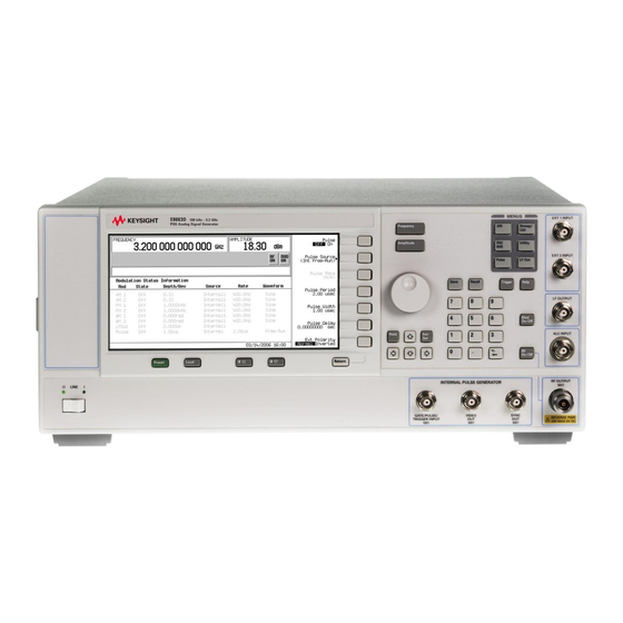
- Page 1 User’s Guide Agilent Technologies E8663B Analog Signal Generator For the latest revision of this guide, go to http://www.agilent.com/find/e8663b and click Product Library. Manufacturing Part Number: E8663- 90003 Printed in USA March 2007 © Copyright 2006- 2007 Agilent Technologies, Inc.
- Page 2 Notice The material in this document is provided “as is,” and is subject to change without notice in future editions. Further, to the maximum extent permitted by applicable law, Agilent disclaims all warranties, either express or implied with regard to this manual and to any of the Agilent products to which it pertains, including but not limited to the implied warranties of merchantability and fitness for a particular purpose.
-
Page 3: Table Of Contents
The E8663B includes the following standard features: ........1... - Page 4 23. ALC INPUT ............. . . 20 Agilent E8663B Analog Signal Generator User’s Guide...
- Page 5 Removing Sensitive Data from E8663B Memory ........
- Page 6 Registers With Previously Stored Instrument States are Empty ......71 Saved Instrument State, but Register is Empty or Contains Wrong State ....71 Agilent E8663B Analog Signal Generator User’s Guide...
- Page 7 Returning a Signal Generator to Agilent Technologies ........
- Page 8 Contents viii Agilent E8663B Analog Signal Generator User’s Guide...
- Page 9 Basic Function Commands • Analog Commands • SCPI Command Compatibility Service Guide • Troubleshooting • Replaceable Parts • Assembly Replacement • Post- Repair Procedures • Safety and Regulatory Key Reference • Key function description Agilent E8663B Analog Signal Generator User’s Guide...
- Page 10 Agilent E8663B Analog Signal Generator User’s Guide...
-
Page 11: Signal Generator Overview
Signal Generator Overview In the following sections, this chapter describes the models, options, and features available for Agilent E8663B signal generator. The modes of operation, front panel user interface, as well as front and rear panel connectors are also described. - Page 12 • RS- 232, GPIB, and 10Base- T LAN I/O interfaces • Type- N female RF output connector The E8663B also offers the following optional features: Option 503—frequency range from 100 kHz to 3.2 GHz Option 509—frequency range from 100 kHz to 9.0 GHz Option UNW—narrow pulse modulation...
-
Page 13: Options
Options Options E8663B signal generators have hardware, firmware, software, and documentation options. The Data Sheet shipped with your signal generator provides an overview of available options. For more information, visit the Agilent E8663B web page at http://www.agilent.com/find/e8663b and click the tab. -
Page 14: Modes Of Operation
In this mode, the signal generator modulates a CW signal with an analog signal. The analog modulation types available are standard pulse, AM, FM, and ΦM. Narrow pulse modulation capability is available with Option UNW. Agilent E8663B Analog Signal Generator User’s Guide... -
Page 15: Front Panel
Softkey labels are located on the right- hand side of the display. For more detail on the front panel display, see “Front Panel Display” on page Agilent E8663B Analog Signal Generator User’s Guide... -
Page 16: Softkeys
Trigger Key Sweep/List hardkey, then one of the following sequences of softkeys: • More (1 of 2) > Sweep Trigger > Trigger Key • More (1 of 2) > Point Trigger > Trigger Key Agilent E8663B Analog Signal Generator User’s Guide... -
Page 17: Menus
Signal Generator Overview Front Panel 9. MENUS These keys open softkey menus for configuring various functions. For descriptions, see the E8663B Signal Generator Key Reference. Table 1-1 Hardkeys in Front Panel MENUS Group E8663B Signal Generator Sweep/List FM/ΦM Utility Pulse... -
Page 18: Lf Output
This female BNC output connector outputs a synchronizing TTL- compatible pulse signal that is nominally 50 ns wide during internal and triggered pulse modulation. The nominal source impedance is 50 ohms. On signal generators with Option 1EM, this output is relocated to the rear panel. Agilent E8663B Analog Signal Generator User’s Guide... -
Page 19: Video Out
Pressing this hardkey causes the display background to darken. 27. Contrast Increase Pressing this hardkey causes the display background to lighten. 28. Local Pressing this hardkey deactivates remote operation and returns the signal generator to front- panel control. Agilent E8663B Analog Signal Generator User’s Guide... -
Page 20: Preset
In standby, the signal generator remains connected to the line power and power is supplied to some internal circuits. 32. Standby LED This yellow LED indicates when the signal generator power switch is set to the standby condition. Agilent E8663B Analog Signal Generator User’s Guide... -
Page 21: Front Panel Display
6. Text Area 3. Annunciators 7. Softkey Label Area 4. Amplitude Area 1. Active Entry Area The current active function is shown in this area. For example, if frequency is the active function, the Agilent E8663B Analog Signal Generator User’s Guide... -
Page 22: Frequency Area
EXT REF This annunciator appears when an external frequency reference is applied. This annunciator appears when frequency modulation is turned on. If phase modulation is turned on, the ΦM annunciator will replace FM. Agilent E8663B Analog Signal Generator User’s Guide... - Page 23 R annunciator). When the R annunciator is on, the front panel keys are disabled, except for the Local key and the line power switch. For information on remote operation, refer to the E8663B Signal Generator Programming Guide. This annunciator indicates when the RF and microwave signal is present (RF ON)
-
Page 24: Amplitude Area
7. Softkey Label Area The labels in this area define the function of the softkeys located immediately to the right of the label. The softkey label may change depending upon the function selected. Agilent E8663B Analog Signal Generator User’s Guide... -
Page 25: Rear Panel
Figure 1- 3 shows a standard E8663B rear panel. Figure 1- 4 on page 16 shows an E8663B rear panel with Option 1EM. Option 1EM moves all front panel connectors to the real panel. Figure 1-3 Standard Rear Panel Diagram 1. - Page 26 13. TRIGGER OUT 21. PULSE VIDEO OUT 6. 10 MHz IN 14. TRIGGER IN 22. PULSE/TRIG GATE INPUT 7. AUXILIARY INTERFACE 15. SOURCE SETTLED 23. ALC INPUT 8. 10 MHz OUT 16. RF OUT Agilent E8663B Analog Signal Generator User’s Guide...
-
Page 27: Source Module Interface
Master/Slave source synchronization. Table 1-2 Auxiliary Interface Connector Pin Number Signal Description Signal Name No Connection (default operation)/ Retrace (Master/Slave operation) Receive Data RECV Transmit Data XMIT +5V (Default operation)/ Sweep Stop (Master/Slave operation) Agilent E8663B Analog Signal Generator User’s Guide... -
Page 28: Mhz Out
0 V at the start of sweep and goes to +10 V (nominal) at the end of sweep, regardless of sweep width. The nominal output impedance is less than 1 ohm and can drive a 2- kohm load. Agilent E8663B Analog Signal Generator User’s Guide... -
Page 29: Trigger Out
“13. LF OUTPUT” on page 20. PULSE SYNC OUT On standard instruments, this connector resides on the front panel. For a description of this connector, see “19. SYNC OUT” on page Agilent E8663B Analog Signal Generator User’s Guide... -
Page 30: Pulse Video Out
“22. GATE/ PULSE/ TRIGGER INPUT” on page 23. ALC INPUT On standard instruments, this connector resides on the front panel. For a description of this connector, see “15. ALC INPUT” on page Agilent E8663B Analog Signal Generator User’s Guide... -
Page 31: Basic Operation
Basic Operation In the following sections, this chapter describes the operation of the Agilent E8663B analog signal generator: • “Using Table Editors” on page 22 • “Configuring a Continuous Wave RF Output” on page 24 • “Configuring a Swept RF Output” on page 26 •... -
Page 32: Using Table Editors
Table Items values arranged in numbered rows and titled columns (The columns are also known as data fields. For example, the column below the Frequency title is known as the Frequency data field). Agilent E8663B Analog Signal Generator User’s Guide... -
Page 33: Modifying Table Items In The Data Fields
4. Use the knob, arrow keys, or the numeric keypad to modify the value. 5. Press Enter The modified item is now displayed in the table. Configuring the RF Output This section provides information on how to create continuous wave and swept RF (page 26) outputs. Agilent E8663B Analog Signal Generator User’s Guide... -
Page 34: Configuring A Continuous Wave Rf Output
You can also adjust the RF output frequency using the knob. As long as frequency is the active function (the frequency is displayed in the active entry area), the knob will increase and decrease the RF output frequency. 8. Use the knob to adjust the frequency back to 700 MHz. Agilent E8663B Analog Signal Generator User’s Guide... - Page 35 RF output amplitude. 2. Turn on the RF output: Press RF On/Off The display annunciator changes to RF ON. At the RF OUTPUT connector, the RF signal is output at the minimum power level. Agilent E8663B Analog Signal Generator User’s Guide...
-
Page 36: Configuring A Swept Rf Output
RF OUTPUT connector is still −10 dBm. Configuring a Swept RF Output An E8663B signal generator has two sweep types: step sweep and list sweep. The signal generator indicates the sweep advance in a progress bar on the front- panel display. If the sweep time is greater than one second, the progress bar sweep advances according to the frequency span of each segment. - Page 37 This changes the start frequency of the step sweep to 500 MHz. 6. Press > > Freq Stop This changes the stop frequency of the step sweep to 600 MHz. 7. Press > > Ampl Start Agilent E8663B Analog Signal Generator User’s Guide...
- Page 38 For convenience, the List Mode Values table can be copied from a previously configured step sweep. Each step sweep point’s associated frequency, amplitude and dwell time values are entered into a row in the List Mode Values table, as the following example illustrates. Agilent E8663B Analog Signal Generator User’s Guide...
- Page 39 This enters 100 ms as the new dwell time value for row 1. Note that the next item in the table (in this case, the frequency value for point 2) becomes highlighted after you press the terminator softkey. 6. Using the arrow keys, highlight the frequency value in row 4. Agilent E8663B Analog Signal Generator User’s Guide...
- Page 40 RF OUTPUT connector. The SWEEP annunciator appears on the display, indicating that the signal generator is sweeping and progression of the sweep is shown by a progress bar. Agilent E8663B Analog Signal Generator User’s Guide...
-
Page 41: Modulating A Signal
On, the MOD ON annunciator shows in the display, whether or not there is an active modulation format. The annunciators simply indicate whether the carrier signal will be modulated when a modulation format is turned on. Agilent E8663B Analog Signal Generator User’s Guide... -
Page 42: Using Data Storage Functions
The Memory Catalog is the signal generator’s interface for viewing, storing, and saving files; it can be accessed through the signal generator’s front panel or a remote controller. (For information on performing these tasks remotely, see the E8663B Analog Signal Generator Programming Guide.) Agilent E8663B Analog Signal Generator User’s Guide... - Page 43 File information appears on the display and includes the file name, file type, file size, and the date and time the file was modified. 2. Press List The “Catalog of List Files” is displayed. 3. Press > Catalog Type State The “Catalog of State Files” is displayed. Agilent E8663B Analog Signal Generator User’s Guide...
-
Page 44: Using The Instrument State Registers
For more information on storing file data such as modulation formats and table entries refer to “Storing Files to the Memory Catalog” on page 33. Refer to the E8663B Analog Signal Generator Programming Guide and the E8663B Analog Signal Generator Key Reference for more information on the save and recall function. NOTE A reference to a file is saved along with the instrument state. - Page 45 Select Seq 3. Press and enter the sequence number containing the registers you want to delete. Select Seq 4. Press Delete all Regs in Seq[n] This deletes all registers in the selected sequence. Agilent E8663B Analog Signal Generator User’s Guide...
-
Page 46: Using Security Functions
E8663B Analog Signal Generator SCPI Command Reference for more information.) Understanding E8663B Memory Types The E8663B signal generator comprises several memory types, each used for storing a specific type of data. Before removing sensitive data, it is important to understand how each memory type is used in the signal generator. - Page 47 512 Bytes no user data Micro- CPU data and instruction cache memory is managed CPU board, not battery backed. processor by CPU, not user Cache (SRAM) 3 kB Agilent E8663B Analog Signal Generator User’s Guide...
-
Page 48: Removing Sensitive Data From E8663B Memory
Using Security Functions Removing Sensitive Data from E8663B Memory When moving the E8663B signal generator from a secure development environment, you can remove any classified proprietary information stored in the instrument. This section describes several security functions you can use to remove sensitive data from your instrument. - Page 49 None − equivalent to a factory preset, no user information is lost Erase − equivalent to Erase All Overwrite − equivalent to Erase and Overwrite All Sanitize − equivalent to Erase and Sanitize All Agilent E8663B Analog Signal Generator User’s Guide...
-
Page 50: Using The Secure Display
The instrument can then be sent to a repair facility for new parts, repair, and calibration. Refer to the E8663B Analog Signal Generator Service Guide for disassembly procedures. Either • Discard the processor board and send the instrument to a repair facility. A new processor board will be installed and the instrument will be repaired and calibrated. -
Page 51: Enabling Options
> > Utility Instrument Adjustments Instrument Options Software Options The following is an example of the signal generator display, which lists any enabled software options, and any software options that can be enabled: Agilent E8663B Analog Signal Generator User’s Guide... -
Page 52: Using The Web Server
The Web Server uses a client/server model where the client is the web browser on your PC or workstation and the server is the signal generator. When you enable the Web Server, you can access a web page that resides on the signal generator. Agilent E8663B Analog Signal Generator User’s Guide... -
Page 53: Activating The Web Server
Manual or DHCP (dynamic host LAN Config Manual DHCP communication protocol) LAN configuration. Refer to E8663B Analog Signal Generator Key Reference for more information. 6. Press the enter key on the computer’s keyboard. The web browser will display the signal generator’s... - Page 54 Basic Operation Using the Web Server Figure 2-5 Signal Generator Web Page Agilent E8663B Analog Signal Generator User’s Guide...
- Page 55 SCPI commands or you can return to the front panel web page. NOTE It may be necessary to use the web browser Refresh function if the web page does not update with new settings. Agilent E8663B Analog Signal Generator User’s Guide...
- Page 56 Basic Operation Using the Web Server Agilent E8663B Analog Signal Generator User’s Guide...
-
Page 57: Optimizing Performance
This overrides the signal generator’s automatic ALC bandwidth selection with your specific selection. For waveforms with varying amplitudes, high crest factors, or both, the recommended ALC loop bandwidth is 100 Hz. Limiting the loop bandwidth of the ALC circuit will prevent the ALC from Agilent E8663B Analog Signal Generator User’s Guide... -
Page 58: Using External Leveling
10 GHz and an amplitude of 0 dBm, follow the instructions in this section. Required Equipment • Agilent 8474E negative detector • Agilent 87301D directional coupler • cables and adapters, as required Connect the Equipment Set up the equipment as shown in Figure 3- Agilent E8663B Analog Signal Generator User’s Guide... - Page 59 Agilent Technologies diode detectors. Using this chart, you can determine the leveled power at the diode detector input by measuring the external detector output voltage. You must then add the coupling Agilent E8663B Analog Signal Generator User’s Guide...
- Page 60 Optimizing Performance Using External Leveling factor to determine the leveled output power. The range of power adjustment is approximately - 20 to +25 dBm. Figure 3-3 Typical Diode Detector Response at 25° C Agilent E8663B Analog Signal Generator User’s Guide...
-
Page 61: Creating And Applying User Flatness Correction
Afterward, use the steps in “Recalling and Applying a User Flatness Correction Array” on page 55 recall a user flatness file from the memory catalog and apply it to the signal generator’s RF output. Agilent E8663B Analog Signal Generator User’s Guide... -
Page 62: Creating A User Flatness Correction Array
Figure 3- NOTE During the process of creating the user flatness correction array, the power meter is slaved to the signal generator via GPIB. No other controllers are allowed on the GPIB interface. Agilent E8663B Analog Signal Generator User’s Guide... - Page 63 This opens the User Flatness table editor and presets the cal array frequency/correction list. 4. Press Configure Step Array This opens a menu for entering the user flatness step array data. 5. Press > > Freq Start 6. Press > > Freq Stop Agilent E8663B Analog Signal Generator User’s Guide...
- Page 64 If you are not using an Agilent E4416A/17A/18B/19B power meter, or if your power meter does not have a GPIB interface, complete the steps in this section and then continue with the user flatness correction tutorial. Agilent E8663B Analog Signal Generator User’s Guide...
- Page 65 2. Press > > > > > > Amplitude More (1 of 2) User Flatness Configure Cal Array More (1 of 2) Preset List Confirm Preset 3. Press > More (2 of 2) Load/Store Agilent E8663B Analog Signal Generator User’s Guide...
-
Page 66: Adjusting Reference Oscillator Bandwidth
To optimize the overall phase noise performance of the signal generator for your particular application, make this adjustment depending on your confidence in the stability and phase noise of the external or internal reference versus the synthesizer hardware for various frequency offsets from the carrier. Agilent E8663B Analog Signal Generator User’s Guide... -
Page 67: To Select The Reference Oscillator Bandwidth
External Ref Bandwidth 2. Select the desired bandwidth. To Restore Factory Default Settings: Internal Timebase: 125 Hz External Timebase: 25 Hz Press > > > Utility Instrument Adjustments Reference Oscillator Adjustment Restore Factory Defaults Agilent E8663B Analog Signal Generator User’s Guide... - Page 68 Optimizing Performance Adjusting Reference Oscillator Bandwidth Agilent E8663B Analog Signal Generator User’s Guide...
-
Page 69: Analog Modulation
Analog Modulation In the following sections, this chapter describes the standard continuous waveform, analog modulation capability, and the optional narrow pulse modulation in the Agilent E8663B Analog Signal Generator. • “Analog Modulation Waveforms” on page 59 • “Configuring AM” on page 60 •... -
Page 70: Configuring Am
In this example, you will learn how to create a frequency- modulated RF carrier. To Set the RF Output Frequency 1. Press Preset 2. Press > > Frequency To Set the RF Output Amplitude Press > > Amplitude dBm. Agilent E8663B Analog Signal Generator User’s Guide... -
Page 71: To Set The Fm Deviation And Rate
Amplitude To Set the ΦM Deviation and Rate 1. Press the hardkey. FM/ΦM FM ΦM 2. Press the softkey. ΦM Dev 3. Press > > pi rad ΦM Rate 4. Press > > Agilent E8663B Analog Signal Generator User’s Guide... -
Page 72: To Activate Fm
The Pulse and RF ON annunciators are now displayed. This indicates that you have enabled pulse modulation and the signal is now being transmitted from the RF OUTPUT connector. The TTL trigger signal state will control pulse modulation output. Agilent E8663B Analog Signal Generator User’s Guide... -
Page 73: Configuring The Lf Output
) is the default LF output source. Internal Monitor Configuring the Internal Modulation as the LF Output Source 1. Press Preset 2. Press the hardkey. FM/ΦM 3. Press > > FM Dev 4. Press > > FM Rate Agilent E8663B Analog Signal Generator User’s Guide... -
Page 74: To Configure The Lf Output With A Function Generator Source
LF Out Off On The LF output is now transmitting a signal using Function Generator 1 that is providing a 3 Vp swept- sine waveform. The waveform is sweeping from 100 Hz to 1 kHz. Agilent E8663B Analog Signal Generator User’s Guide... -
Page 75: Troubleshooting
Troubleshooting This chapter provides basic troubleshooting information for the Agilent E8663B analog signal generator. If you do not find a solution here, refer to the E8663B Analog Signal Generator Service Guide. NOTE If the signal generator displays an error, always read the error message text by pressing >... -
Page 76: Rf Output Power Too Low
The Power Supply has Shut Down If the power supply is not working, it requires repair or replacement. There is no user- replaceable power supply fuse. Refer to the E8663B Analog Signal Generator Service Guide for instructions. Signal Loss While Working with a Mixer If you experience signal loss at the signal generator’s RF output during low- amplitude coupled... - Page 77 RF output of the signal generator and the input of the mixer. The signal generator’s ALC level is increased to +2 dBm and transmitted through a 10 dB attenuator to achieve the required - 8 dBm amplitude at the mixer input. Agilent E8663B Analog Signal Generator User’s Guide...
-
Page 78: Signal Loss While Working With A Spectrum Analyzer
Use the following steps to set the signal generator to the ALC off mode: 1. Preset the signal generator: press Preset 2. Set the desired frequency: press and enter the desired frequency. Frequency 3. Set the desired amplitude: press and enter the desired amplitude. Amplitude Agilent E8663B Analog Signal Generator User’s Guide... -
Page 79: No Modulation At The Rf Output
Power search mode executes a power search routine that temporarily activates the ALC, calibrates the power of the current RF output, and then disconnects the ALC circuitry. See the E8663B Analog Signal Generator Key Reference for more information on the Power Search function. -
Page 80: Sweep Problems
The TTL/CMOS output available at the TRIG OUT connector, however, is asserted high only during the actual dwell time. If the list dwell values are correct, continue to the next step. Agilent E8663B Analog Signal Generator User’s Guide... -
Page 81: List Sweep Information Is Missing From A Recalled Register
If either error message −311 or −700 is stored in the error message queue, the signal generator’s battery has failed. 6. Refer to the E8663B Analog Signal Generator Service Guide for battery replacement instructions. Saved Instrument State, but Register is Empty or Contains Wrong State If you select a register number greater than 99, the signal generator automatically selects register 99 to save the instrument state. -
Page 82: Cannot Turn Off Help Mode
Local • Make sure that the signal generator is not in local lockout condition. Local lockout prevents front panel operation. For more information on local lockout, refer to the E8663B Analog Signal Generator Programming Guide. • Check for a progress bar on the signal generator display, which indicates that an operation is in progress. -
Page 83: Error Messages
If an error condition occurs in the signal generator, it is reported to both the front panel display error queue and the SCPI (remote interface) error queue. These two queues are viewed and managed separately; for information on the SCPI error queue, refer to the E8663B Analog Signal Generator Programming Guide. -
Page 84: Error Message File
These codes are also used for self- test response errors. Errors in this class set the device- specific error bit (bit 3) in the event status register (IEEE 488.2, section 11.5.1). Agilent E8663B Analog Signal Generator User’s Guide... -
Page 85: Contacting Agilent Sales And Service Offices
Returning a Signal Generator to Agilent Technologies To return your signal generator to Agilent Technologies for servicing, follow these steps: 1. Gather as much information as possible regarding the signal generator’s problem. - Page 86 Troubleshooting Returning a Signal Generator to Agilent Technologies Agilent E8663B Analog Signal Generator User’s Guide...
- Page 87 59–64 description, annunciators, application notes obtaining, ARMED annunciator, data arrow hardkeys, fields, editing, ATTEN HOLD annunciator, files, attenuator, external leveling, input methods, automatic leveling control. See ALC removal, AUXILIARY INTERFACE connector, sensitive, 36, Agilent E8663B Analog Signal Generator User’s Guide...
- Page 88 See FM erase and sanitize, offset, erasing memory, 36, 38, 39, ranges, ERR annunciator, 12, reference, error messages RF output, setting, display, front panel message format, description, 5–11 overview, disabling keys, queue, types, annunciators, Agilent E8663B Analog Signal Generator User’s Guide...
- Page 89 RS-232, physical location, interface, remote, sanitizing, secure mode, size, key, license, types, keypad, numeric, waveform, keys writing to, disabling, MENUS hardkeys, front panel, 5–10 mixer, signal loss while using, knob, front panel, Agilent E8663B Analog Signal Generator User’s Guide...
- Page 90 See LF output and RF output recovery sequence, fail-safe, OVEN COLD annunciator, reference overwriting memory, amplitude, setting, frequency, setting, oscillator bandwidth, adjusting, references, Page Down softkey, registers, 34, Page Up softkey, remote operation, 7, performance, optimizing, 47–57 Agilent E8663B Analog Signal Generator User’s Guide...
- Page 91 22–23 service, Agilent sales and service offices, talker mode annunciator, shape files, TCP/IP, signal generator technical support, features, text display area, firmware trigger firmware, hardkey, models, inputs modes, GATE/PULSE/TRIGGER, Agilent E8663B Analog Signal Generator User’s Guide...
- Page 92 UNW, option, 2, 4, 59, upgrading firmware, user documentation, user flatness, 32, 51–56 user-defined files, VIDEO OUT connector, VIDEO OUT connector (rear), waveform memory, waveforms analog modulation, file catalogs, web server, website web page, WFM1 files, Agilent E8663B Analog Signal Generator User’s Guide...