Table of Contents
Advertisement
Quick Links
Advertisement
Table of Contents

Related Manuals for JRC JAN-701B


Summary of Contents for JRC JAN-701B
- Page 1 JAN-701B/901B JAN-701B/901B ECDIS ECDIS INSTRUCTION INSTRUCTION MANUAL MANUAL...
- Page 3 Cautions for High Voltage High voltages, ranging from several hundreds to tens of thousands of volts, are used in electronic apparatus, such as radio and radar instruments. These voltages are totally harmless in most operations. However, touching a component inside the unit is very dangerous.
- Page 4 Method of First-Aid Treatment ☆Precautions for First-Aid Treatments Whenever a person is struck by an electrical shock, give the patient artificial respiration immediately on the spot, unless it is absolutely necessary to move the patient for safety's sake. Once started, artificial respiration should be continued rhythmically. (1) Refrain from touching the patient carelessly as a result of the accident;...
- Page 5 ☆Treatment to Give When the Patient Has a Pulse Beating but Has Ceased to Breathe *Performing mouth-to-mouth artificial respiration - Fig. 1 (1) Bend the patient's face backward until it is directed to look back. (A pillow may be placed under the neck.) (2) Pull up the lower jaw to open up the airway.
- Page 6 ☆Treatment to Give When the Patient Has No Pulse Beating and Has Ceased to Breathe *Performing cardiac massage - Fig. 2 If the patient has no pulse beating, with the pupils open and no heartbeat being heard, the patient has a cardiac arrest and requires immediate artificial respiration. Continue this until a medical specialist arrives, and follow his or her directions after that.
- Page 7 ● Keep this manual in a convenient place for future reference. Make use of this manual when experiencing operation difficulties. ● This LCD uses 1,310,000 (JAN-701B)/1,920,000 (JAN-901B) or more TFTs (Thin Film Transistor). If some pixels on the screen are not clear, the color is different, or the screen is brighter than usual, it is not because of defect, instead it is because of inherent characteristic of the TFT display technology.
- Page 8 ● Before Operation ● Pictorial Indication Various pictorial indications are included in this manual and are shown on this equipment so that you can operate them safely and correctly and prevent any danger to you and / or to other persons and any damage to your property during operation.
- Page 9 ● Precautions Upon Equipment Operation ● Never remove the cover of this equipment. Touching the high-voltage section inside will cause an electric shock. Do not attempt to disassemble or tamper with this equipment. Otherwise, a fire, an electric shock, or a malfunction may occur. Do not place a glass or cup containing water, etc., or a small metal object on this equipment.
-
Page 10: Specifications
If the LCD module breaks and the liquid inside spills out to stick to your skin, wash it off immediately under running water for more than 15 minutes. If you find any skin problem afterwards, consult a doctor immediately. If the liquid gets in your eye, wash it off immediately under running water for more than 15 minutes, and then, consult a doctor as soon as possible. - Page 11 Do not use or leave the equipment under direct sunlight or in the temperatures above 55°C for a long time. Otherwise, a fire or a malfunction may occur. Do not block the ventilation opening of the equipment. Otherwise, heat may accumulate inside to cause a fire or a malfunction. This equipment is intended for use as an aid to navigation only.
- Page 12 Do not turn on the power of the equipment with a floppy disk inserted in the floppy disk drive. The equipment will not start normally. If checking of the equipment is unavoidably necessary, be sure to turn off the power before starting checking. Otherwise, a fire or a malfunction may occur.
- Page 13 Do not leave the USB Storage in the USB port after use. Malfunctions may result. In the case of turning on the power under the condition of low temperature, do pre-heat less than 30 minutes. The equipment will not start normally. Recover the system with [Recovery Boot CD] after reading an explanation well, and having understood the function of [Recovery Boot CD] enough.
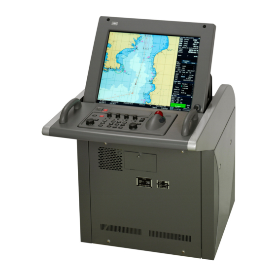
- Page 14 Equipment Appearance Stand-alone type (JAN-701B)
- Page 15 Stand-alone type (JAN-901B) xiii...
- Page 16 Glossary : Automatic Identification System ARCS : Admiralty Raster Chart Service. A raster chart published by UKHO. ARPA : Automatic RADAR Plotting Aid. Collision prevention radar. AUTHORIZATION CODE : Encryption key for C-MAP Ed.2. Supplied by C-MAP Norway. AUTO SAIL : The system automatically navigates to keep the scheduled route.
- Page 17 : Great Circle : Ship’s heading Hydrographic and Oceanographic Department: Hydrographic and Oceanographic Department of Japan Coast Guard. Publisher of ENC. Import (for Chart Portfolio) : A procedure of enabling the chart supplied by Base CD to be displayed on ECDIS.
- Page 18 : Chart CD containing the chart data updated from Base CD. Base CD data has been imported. USER CODE : A user-specific code assigned by JRC. Required in using ARCS and S-63 charts. : Universal Time, Coordinated : Variable Range Markers...
-
Page 19: Table Of Contents
Contents PREFACE ..............................v ● Before Operation ● ..........................vi ● Precautions Upon Equipment Operation ● ..................vii Glossary ..............................xiv 1 Overview ...............................1-1 1.1 Function....................................1-2 1.2 Features ....................................1-4 1.3 Components.................................... 1-5 1.4 Construction ................................... 1-6 1.5 System Configuration................................1-12 2 Names and Functions ...........................2-1 2.1 Function of Operation Panel and LCD brilliance control .................. - Page 20 3.3.5 Adjusting the Brightness and Sound Volume ............3-24 3.3.6 Changing the Display Color ([DAY/NIGHT])............3-28 3.3.7 How to Release the Alarm ([ALARM ACK]) ............3-30 3.3.8 Displaying the Radar Image ([RADAR])..............3-37 3.3.9 The AIS/TT target Display ..................3-40 3.3.9.1 AIS/TT display ON/OFF ................3-40 3.3.9.2 Opening the AIS/TT list .................3-41 3.3.9.3 Target Track ....................3-46 3.3.9.4 File operation ....................3-49...
- Page 21 3.11.2 Selecting an Area ....................3-87 3.11.3 Wide Range View Screen (S-57/C-MAP Only) .............3-88 3.12 Selecting Route and To WPT ............................3-89 3.12.1 Selecting Route and To WPT Using the Display Panel.........3-89 3.12.2 Distance Measurement ..................3-91 3.12.3 Use XTD Alarm......................3-94 3.13 Displaying a User Map ..............................3-95 3.14 Reading Out Information on the Object ........................3-96 3.15 Operating EBL/VRM ...............................3-99 3.15.1 Operating EBL/VRM Using the Operation Panel ..........3-99...
- Page 22 3.27.4 Track and Time Label Display ................3-157 3.27.5 Heading Line and Beam Line................3-158 3.28 Chart Setting................................... 3-159 3.28.1 Chart Setting S-57/C-MAP/ARCS ...............3-159 3.28.1.1 Setting the "View Common" tab ..............3-160 3.28.1.2 Setting the "View1" tab................3-168 3.28.1.3 Setting the "View2" tab................3-174 3.28.2 Other Chart Setting .....................3-175 3.28.3 Save Chart Setting ....................3-176 3.28.4 Chart Setting List....................3-177 3.29 Chart Abbreviations ..............................
- Page 23 4.2.1 Operation Flowchart ....................4-57 4.2.2 Creating Alternate Route..................4-58 5 Chart Editing ............................5-1 5.1 Chart Edit Mode ..................................5-3 5.2 Menus and Button Functions............................5-4 5.2.1 Chart Editing Menu....................5-4 5.2.2 Button Functions .......................5-8 5.3 User Map Editor Operation ............................... 5-9 5.3.1 Flow of User Map Edit ....................5-9 5.3.2 Operation when Editing User Map ................5-11 5.3.2.1 Creating a New User Map................5-11 5.3.2.2 Editing a User Map ..................5-14...
- Page 24 7.7 Setting the User Key.................................7-12 7.8 Setting Date/Time ................................7-13 7.9 Clear Voyage Distance ..............................7-14 7.10 Setting the Alarm Options............................7-15 7.11 Radar Process Setting ..............................7-17 7.12 Language....................................7-17 7.13 Code Input...................................7-18 7.14 Analog Correct Value ..............................7-19 7.15 Own ship’s Parameter Setting ...........................7-20 7.15.1 Ship’s Parameter....................7-20 7.15.2 CCRP Setting ......................7-21 7.16 Line Monitor..................................7-22...
- Page 25 10.5.1 Displaying/Hiding the User Maintenance Menu ............10-8 10.5.2 Disk Information ....................10-11 10.5.2.1 Drive Information..................10-11 10.5.2.2 File Information ..................10-12 10.5.3 Backup / Restore....................10-13 10.5.3.1 How to Backup from HDD to USB device..........10-13 10.5.3.2 How to Restore from USB device to HDD ..........10-16 10.5.4 Hardware Key Information ..................10-18 10.5.5 CD Cleaner......................10-19 10.6 Troubleshooting................................
- Page 26 15 Specifications ............................15-1 15.1 Bridge Display Terminal ..............................15-2 Index ................................1 END-USER LICENSE AGREEMENT FOR JAN-701B/901B SERIES ECDIS SOFTWARE......3 Repair Request Form..........................5...
-
Page 27: Overview
Overview... -
Page 28: Function
• Display symbols used to present chart information are presented in accordance with S-52 and its appendices. • Display specifications Size: 19-inch color LCD (JAN-701B) 23.1-inch color LCD (JAN-901B) Selection of colors (conforming to the IMO/IHO) suitable for the daytime, nighttime, dawn, and dusk Display of the symbols and colors recommended by the IHO. - Page 29 Alarm functions • Safety depth crossing alarm • Dangerous areas crossing alarm • Waypoint arrival alarm ECDIS • XTD alarm Logging functions • Logging of navigation information onto the hard disk • Own ship’s playback using logged data 1 Overview...
-
Page 30: Features
1.2 Features This ECDIS has the following features: ECDIS functions: • Displays vector charts such as S-57 and C-MAP, and raster charts such as ARCS • Safe navigation ensured by the crossing alarm function for safety contours and dangerous areas and the guard ring function (not available for ARCS) •... -
Page 31: Components
1.3 Components A list of components and optional accessories is shown below. ECDIS • Components Name Model Quantity Comment Display Unit (JAN-701B) NCD-2095 Main Unit (JAN-901B) NCD-2096 (JAN-701B) NWZ-173-E Monitor Unit Included in the main unit (JAN-901B) NWZ-170-E Operation Unit NCE-5163-E -... -
Page 32: Construction
1.4 Construction The outline drawing of the unit is shown below. Mass: Approx. 125 kg Cable Inlet Warning label NCD-2095 Bridge Display Terminal (JAN-701B) (UNIT: mm) 1 Overview... - Page 33 ECDIS Mass: Approx. 150kg Cable Inlet Warning label NCD-2096 Bridge Display Terminal (JAN-901B) (UNIT: mm) 1 Overview...
- Page 34 1 Overview...
- Page 35 ECDIS 1 Overview...
- Page 36 1 Overview 1-10...
- Page 37 ECDIS MASS:APPROX. 3.5kg NCE-5163-E Operation Panel 1-11 1 Overview...
-
Page 38: System Configuration
1.5 System Configuration The following diagram shows an example system configuration connected with this equipment. When ECDIS mode is used, it displays navigation data received from the sensor. / CONNING 1 Overview 1-12... -
Page 39: Names And Functions
Names Functions... -
Page 40: Function Of Operation Panel And Lcd Brilliance Control
This equipment can be operated both from the Operation panel and the display. 2.1 Function of Operation Panel and LCD brilliance control (1) Function of operation panel Fig. 2.1 and Fig. 2.2 show the operation panel. Table 2.1 describes the name and function of each part on the operation panel. - Page 41 Table 2.1 Names and Functions Name Function POWER Turns the power on. PWR FAIL Indicates the AC power supply error. (See 10.4 “The PWR FAIL Lamp and Power Supply Input.”) PWR ACK Stops the alarm at occurrence of PWR FAIL. ECDIS (See 10.4 “The PWR FAIL Lamp and Power Supply Input.”) VIDEO...
- Page 42 The screen’s brightness can be adjusted by using the brilliance control on the display panel. By keeping the brilliance control pressed, the screen’s brightness will be adjusted to an optimal condition automatically. • JAN-701B Brilliance control • JAN-901B Brilliance control Note: •...
-
Page 43: Function Of The Screen (Ecdis)
2.2 Function of the Screen (ECDIS) The functions of the display of the ECDIS unit are described here. The screen consists of three areas, the chart display area, TCS bar and display panel (information display area). The menu title bar appears when this equipment enters the menu mode. ECDIS Menu title bar North arrow mark... - Page 44 TCS Bar: Information bar for Auto Sail. Most of the items in the TCS bar display a value by choosing route on the Display Panel. To WPT: Number of “To WPT” Next WPT: Next number of “To WPT” TTG: Estimated Time of Arrival at the “To WPT” ETA: Speed to arrive at the “to WPT”...
-
Page 45: Display Panel
2.2.1 Display Panel The contents of display panel will change according to the chart being selected, either S-57/C-MAP or ARCS. The following shows the typical displays common to S-57/C-MAP and ARCS ECDIS Own Ship Information; See 2.2.1.1. The other ship displaying status; See 2.2.1.2. Auto sailing status. -
Page 46: Own Ship Information
2.2.1.1 Own Ship Information 1) The Basic Information Chosen CCRP (Consistent Common Reference Point): The picture freeze indicator: CCRP can be set from four (CCRP1-CCRP4). The This indicator is animating while the CCRP setting can be changed in menu [Serviceman] - screen-display is working normally. - Page 47 Note: The following item can change setting in menu [Main]-[Sensor]. ・ Heading Sensor: It chooses from the connected equipment or manual setting. ・ STW Sensor: It chooses from the connected equipment or manual setting. ・ POSN1 (Primary sensor): It chooses from the connected equipment or Dead Reckoning. ・...
-
Page 48: The Other Ship Displaying Status
2.2.1.2 The Other Ship Displaying Status In case of setting to display on the chart about the other ship information, an information name is displayed in this column. ① RADAR 1 or RADAR 2 : [MENU]-[(7)Main] – [(9)Radar Overlay]- [(1)Radar 1] or[(2)Radar 2] ②... - Page 49 Other Ship Information displaying procedure: ① RADAR1 or RADAR2 When selecting [MENU]–[(7) Main]–[(9) Radar Overlay]–[(1)Radar 1], it is displayed with [RADAR1]. When selecting [MENU]–[(7) Main]–[(9) Radar Overlay]–[(2)Radar 2], it is displayed with [RADAR2].. It becomes blank when making the check of [Radar Overlay] invalid. ECDIS [RADAR1] or [RADAR2] is as displayed even if it does an off center in the radar overlay and it makes Radar Overlay off.
-
Page 50: Auto Sailing Status
2.2.1.3 Auto Sailing Status The auto sailing status panel will be displayed as follows: Displays the autopilot steering mode. See the autopilot instruction manual for descriptions of the various steering modes. BLANK: Not Auto Sailing MAN: Manual turning mode BLANK: Not Auto Sailing AUTO: Auto turning mode KEEP: Keep tracking the current leg DIRECT: Direct route to Waypoint... -
Page 51: The Other Information On The Own Ship
2.2.1.5 The other information on the own ship CALC: (Actual Speed) Destined waypoint (selectable from the drop-down list) Distance from the ship to the “to destined waypoint” ECDIS Actual Speed Estimated Time of Arrival at the “to destined waypoint” Speed to arrive at the “to destined waypoint” by the planned time Actual Speed mode: The mode switches over by clicking this button. - Page 52 WPT: Name of displayed WPT Latitude of displayed WPT Longitude of displayed WPT Select from To / Next To: Displays “To WPT” Next: Displays Next to “To WPT” Pair: [Pair] tab isn't displayed when not using TCS type Auto Pilot. Plan course, actual heading azimuth of own ship are displayed.
-
Page 53: Chart Information For S-57/C-Map
2.2.1.6 CHART Information for S-57/C-MAP When left-clicked, EVENT mark is put at the own ship position. When left-clicked, MOB (Man-Over-Board) panel opens. When left-clicked, shows the registered port name list. ECDIS Selected port name position will be displayed on the chart. The selecting Drop-down list is lit in green. -
Page 54: Chart Information For Arcs
2.2.1.7 CHART Information for ARCS Note: •Function of the [EVENT], [PORT LIST] and [HOME] buttons is the same as for S-57/C-MAP. Displays the geodetic system of the chart. Displays the original scale of the chart. Scale Of the chart being displayed Range of the chart being displayed Motion (selectable with the drop-down list button) True: Your ship moves on the chart. -
Page 55: Tools Panel
2.2.1.8 Tools Panel Refer to 3.15.3 Units of distance switch button Azimuth of EBL switch button When left-click, units of VRM distance is changed. T: True North mode [NM] -> [km] -> [sm] -> [NM] -> … ECDIS R: Bearing Reference mode Tool area switch button Displaying position of cross point on EBL1 and VRM1... -
Page 56: Brilliance Setting Panel
2.2.1.9 Brilliance Setting Panel Refer to 3.3.5. Tool area switch button Day-Night level switch button When left-click, display level is changed. [DAY1]-> [DAY2]-> [DAY3]-> [DUSK]-> [NIGHT]-> [DUSK]-> [DAY3]… AIS/Tracked Target brightness switch button Changing 0 to 4 level every Day-Night level. Video brightness switch button (In using radar) Changing 1 to 4 levels every Day-Night level. -
Page 57: Menu Title Bar
2.2.2 Menu Title Bar When you move the cursor top of screen, the menu title bar opens and you can access to various menus. ECDIS The following shows the menu trees: Table 2.2 Menu Tree Main Menu Submenu Submenu/Option Reference (1) AIS/TT (1) TT1 3.3.9.2... - Page 58 Table 2.2 Menu Tree -- Continued Main Menu Submenu Submenu/Option Reference (4) Ownship/Track (2) Anchor Watch (1) Create Monitoring Circle 3.17 (2) Clear Monitoring Circle 3.17 (0) Setting… 3.27 (5) User Map (1) Select User Map… 3.13 (2) Unselect User Map 3.13 (3) User Map Editor (6) Chart...
- Page 59 Table 2.2 Menu Tree -- Continued Main Menu Submenu Submenu/Option Reference (7) Main (1)Create Lop 3.22 (4) LOP (2)Delete All LOP 3.22 (5) Print 3.35 (6) Save Screen 3.36 (7) Logbook 3.26.1 ECDIS (1) PreSet (8) Multi Window 3.24.2 (2) Analog Meter 3.24.1 (3) Climate 3.24.2...
-
Page 60: Servicem Ship's Parameter
Table 2.2 Menu Tree -- Continued Main Menu Submenu Submenu/Option Reference (1) Serviceman (1) Line Monitor 7.16 (2) Adjust 7.17 (1) Installation Information (3) Installation 7.18 (2) CCRP Setting 7.15.2 (4) Ship's Parameter 7.15.1 (5) TCS Maintenance… 7.19 (6) Radar Initial Setup… 7.20 (1) Backup (7) Data Backup/Restore... - Page 61 Context Menu Main Menu Submenu Reference 3.1.1.3 Abort Activate AIS 3.3.9 3.3.9 Deactivate AIS 3.3.9 TGT Data ECDIS 3.3.9 Cancel TGT Data 3.3.9 TGT Property 3.14 S-57/C-MAP /ARCS Information 3.14 Other Information Auto mode 3.25 3.5.1 Zoom Area 3.15.2.2 Dropped EBL/VRM EBL1/VRM1 3.15.2.2 EBL2/VRM2...
-
Page 63: Basic Operation Of Ecdis
Basic Operation of ECDIS... - Page 64 ● Do not place any object on the operation panel. Avoid placing anything extremely hot, in particular, as this may deform the panel. ● Do not apply any undue shock on the operation panel, trackball and dials. Otherwise, a malfunction may result. Notes on Description: (1) Keys/Buttons/dials/menu names: The keys on the operation panel, buttons on the display panel and the menu names are written as...
-
Page 65: Menu Operation
3.1 Menu Operation To operate this equipment, it is necessary to know how to select menus and set options in the menus. Basic procedure to access to a menu and set options using the trackball section are described here. Also, major panel (dialog box, etc.) types that will appear during operation, and how to enter numbers and letters are described. - Page 66 Major cursors Cross Cursor Lens Cursor Indicates the position on the chart. Appears when area zoom function is selected. The rubber band can be Marking Cursor drawn to magnify an area. Appears while operation in following Hand Cursor modes. Appears when the cursor is moved while pressing and holding down the ・Information Mark left button in the chart area.
-
Page 67: How To Select The Menu
3.1.1.2 How to Select the Menu As for example, the following menu operation is described here. Select [MENU] - [(6) Chart] - [(1) Marking/Highlighting] - [(2) Information Mark] in that order. The general menu selection procedure is as follows: (1) Opening the menu (entering Menu mode) (2) Selecting the menu (3) Selecting the submenu/options ECDIS... - Page 68 (2) Selecting [(6) Chart] ([MENU] - [(6) Chart]) Select the [(6) Chart] on the menu title bar. The Chart menu will open. Step-by-step operation to select [(6) Chart] menu: 1) Rotate the trackball to move the cursor to [(6) Chart] on the menu title bar. 2) Left-click the left button on the trackball section to select the [(6) Chart] menu.
- Page 69 (3) Selecting [(1) Marking/Highlighting] - [(2) Information Mark] 1) Left-click [(1) Marking/Highlighting] on the Chart menu. Then, the Marking/Highlighting submenu will open. 2) Left-click [(2) Information Mark]. Then, the “Location/Attribute” panel will open. Shifting the cursor will also open the submenu.
-
Page 70: How To Use The Context Menu
3.1.1.3 How to Use the context Menu You may use the context menu by pressing the right button (by right-clicking). Example: By right-clicking on the chart display Right-clicking the chart may open a context menu. Left-click a menu item you want. e.g. - Page 71 Note: In case of various operations which used the cursor, the operation can be aborted by choosing "Abort" of the context menu. Right-clicking on the chart may open a shortcut menu. ECDIS Left-click “Abort” to abort the current COG: 3 Basic Operation of ECDIS...
-
Page 72: Various Panels
3.1.2 Various Panels The major panel types that will appear on the screen and how to operate them are described here. Value entry box You can enter numbers. 1) First, left-click the entry box. 2) Next, enter the value. 3) To fix the entry, select other value entry box, if any, or the [ENT] key. - Page 73 Tabs You can display one of panels by selecting a tab. 1) Left-click one of tabs to display a panel. Check box Left-click the item to turn it ON or OFF. ECDIS The check mark (✔) shows that the selected item is set to ON. Option button (Radio button) You can select one of items you want.
-
Page 74: How To Enter Numbers And Letters
3.1.3 How to Enter Numbers and Letters You can enter numbers and letters into the value entry box or text box using the alphanumeric graphic buttons on the display or optional full key board. 3.1.3.1 Use of the PS/2 Keyboard Note: •... -
Page 75: Use Of The Software Keyboard
3.1.3.2 Use of the Software Keyboard To input data, you can use numerical keyboard or Like the PS/2 keyboard. By the column, the kind of the keyboard is changes. Numerical keyboard: Left-click to value entry box, numerical keyboard is displayed. (See 3.1.3.3 Numerical Input) ECDIS (Input a number) -
Page 76: Numerical Input
3.1.3.3 Numerical Input This section explains the numerical input rules. •Inputting number is displayed value entry box. •The function of each button is as follows. [1] ~ [9], [0]: Input number is displayed right side that likes an electronic calculator. [+]/[-], [N]/[S], [E]/[W]: Change contents except a number. - Page 77 4) After inputting [LAT], left click the [S] bottom. ECDIS Input [ENT] on software keyboard, the software keyboard is closed and the input data is fixed. 3-15 3 Basic Operation of ECDIS...
-
Page 78: Character Input
3.1.3.4 Character Input This section explains the character input rules. •Inputting character is displayed on software keyboard. When fix data, the text area is entered the data. •The input character is displayed behind a character cursor. The character cursor is moved by “<-”, “->” key or left-clicking on input area. -
Page 79: General Flowchart
3.2 General Flowchart The following shows a general flowchart to use JAN-701B/901B and the flowchart for sailing. 3.2.1 General Flowchart [Startup Menu] [Startup Screen] Power switch ON ECDIS Select [Navigation & Planning] in Startup Menu Startup Screen Input ARCS PIN (ARCS only) [Navigation &... -
Page 80: Flowchart For Sailing
3.2.2 Flowchart for Sailing Alarms: If an alarm occurs, the alarm panel will blink in red and a sound will be Sailing start heard. Check the alarm contents and, after confirming it, press the [ALARM ACK] key on the operation panel. Pressing the [Alarm List] on the display panel shows the alarm contents. - Page 81 Flowchart for Sailing -- Continued The sequel from the pre-page • When the ship crosses a waypoint boundary, there will be an updated next WPT, and an “Arrived at WPT” alarm occurs. After confirming the alarm contents, press the [ALARM ACK] key on the Route monitoring ("Arrived at WPT"...
-
Page 82: Power On/Off And Preparation
3.3 Power ON/OFF and Preparation How to turn the power ON and OFF and preparation before sailing are described here. Note that, when you turn the power OFF, you must terminate the system by following the termination sequence described here. Also, how to recover the system in case of hung up is explained. -
Page 83: Selecting The Startup Menu
3.3.2 Selecting the Startup Menu The power turns on, and the [POWER] key will light. After a short while, the Startup menu will be displayed. You can select one of items. ●Navigation & Planning If [ ] is left-clicked, the [Startup screen] will first appear, and then the Navigation & Planning screen will be displayed. -
Page 84: Startup Screen And Arcs Pin Input (Arcs Only)
3.3.3 Startup Screen and ARCS PIN Input (ARCS Only) 1) If ARCS has been installed, the “ARCS PIN” panel will be displayed after [Navigation & Planning] is selected in the Startup menu. Input the ARCS PIN and left-click on the [OK] button. The [Startup screen] will be displayed if the inputted ARCS PIN is correct and the [OK] button is left-clicked on the “ARCS PIN”... - Page 85 2) After the Startup screen appears, the Navigation & Planning screen will be displayed after a short while. [Navigation & Planning Screen (Example)] ECDIS 3-23 3 Basic Operation of ECDIS...
-
Page 86: Power Off Operation
Adjusting the Brightness and Sound Volume Perform the following adjustments as required. (1) Brightness of the screen ([BRILL]) Adjust the Brilliance control on the LCD monitor to adjust the brightness on the screen. • JAN-701B • JAN-901B Brilliance control Brilliance control... - Page 87 (2) Brightness of the operation panel ([PANEL]) Key operation: 1) On the operation panel Press the [PANEL] key. Each time you press the key, the operation panel brightness changes. You can adjust the brightness in five steps. Menu operation: ECDIS 1) In the normal menu Select [MENU] - [(7) Main] - [(0) Setting] - [(1) Color and Brilliance Setting] in that order.
- Page 88 (4) Brightness of the AIS/TT target symbol ([TGT]) Menu operation: 1) In the normal menu Select [MENU] - [(7) Main] - [(0) Setting] - [(1) Color and Brilliance Setting] in that order. In the Table Editing menu, Graphic Editing menu Select [MENU] - [(6) Main] - [(0) Setting] - [(1) Color and Brilliance Setting] in that order.
- Page 89 2) The alarm volume is changed in seven steps by moving the scroll bar of each alarm type. 3) To fix the changed setting and to close the panel, press “OK”. When pressing “Cancel” , the panel is closed and the setting returns to the original condition. *1 The volume of lift click sound remains the same regardless of the sound level setting.
-
Page 90: Changing The Display Color ([Day/Night])
3.3.6 Changing the Display Color ([DAY/NIGHT]) You can change the display color to obtain optimum display matched with the lighting conditions on the bridge. Select one of the following display colors ● DAY1 (Day Bright) ● DAY2 (Day Whiteback) For S-57/C-MAP only ●... - Page 91 Tool area on display panel operation: 1) Tool area is switched from [Tools] to [Brilliance] with tool area switch button. 2) Display color is changed by [Day-Night level] switch button. [Day-Night level] switch button Each time you press the key, the display color changes. The order which a display color switches ECDIS over to is the same as the key operation.
-
Page 92: How To Release The Alarm ([Alarm Ack])
3.3.7 How to Release the Alarm ([ALARM ACK]) When the alarm occurs, the buzzer sounds and the alarm contents are displayed in the alarm display area on the display panel to notify the operator of an alarm. When more than one alarm occurs, it changes an alarm display every second. - Page 93 (3) Acknowledging and canceling of the alarm (Stopping the alarm sound) Notes: Until it confirms the cause of the alarm, don't acknowledge an alarm. 1) The procedure of the alarm acknowledgement operation On the operation panel Press the [ALARM ACK] key. ECDIS On the display panel Left-click the alarm acknowledge-button.
- Page 94 (4) Displaying the alarm list 1) At any time, left-click the [Alarm List] button on the display panel. Then, the “Alarm List” panel opens. • If you open the “Alarm List” panel when the alarm blinks, the alarm button in the “Alarm List” also blinks.
- Page 95 2) Left-click the [Close] button to close the “Alarm List” panel. * When opening Alarm List once again, the tab to have been selecting last opens. Detailed Alarm List refers to "9.1Alarm Function". Icon blinks in red: Title of the tab displaying red: The alarm occurs and it is not acknowledged yet.
- Page 96 [System Alarm Status] tab: [System alarm status] is the alarm list of the hardware error and the communication error. [System alarm status] is displaying, dividing into the category below: ・No.1 Position Data Alarm ・No.2 Position Data Alarm ・No.1 Position Shift Alarm ・Position Difference Alarm ・Radar Data Alarm ・Target Data Track Alarm...
- Page 97 (5) Displaying the alarm Log table You can display the alarm Log on the sailing. Note: • The alarm history is displayed only latest 20 items. To check the past alarm lists, see 3.26 “Logbook”. Menu operation: 1) In the normal menu ECDIS Select [MENU] - [(7) Main] - [(3) Test] - [(1) Alarm Log] in that order.
- Page 98 2) Left-click the [Close] button to close the “Alarm List” panel. Alarm: Detected: Acknowledge: Removed*: Displaying alarm Displaying date when Displaying date when the Displaying date when contents the alarm occurred. alarm acknowledged. the alarm removed. Icon blinks in red: The alarm occurs and it is not acknowledged yet.
-
Page 99: Displaying The Radar Image ([Radar])
3.3.8 Displaying the Radar Image ([RADAR]) You can turn ON/OFF the radar image on the chart. The radar image can be adjusted with the dials on the operation panel. Note: • To display a radar image, the optional radar board must be installed on the unit. Also, a radar image must be sent from the radar system. - Page 100 Turning ON/OFF the Range Rings: 1) In the normal menu Select [MENU] - [(7) Main] - [(9) Radar Overlay] - [(3) Range Rings] in that order. In the Table Editing menu, Graphic Editing menu, User Chart Editing menu Select [MENU] - [(6) Main] - [(9) Radar Overlay] - [(3) Range Rings] in that order. Each time you left-click [(3) Range Rings], the range ring display is turned ON and OFF.
- Page 101 (4) Radar image adjustment (on the operation panel) Note: • If menu panel adjustment ([(7) Main] - [(9) Radar Overlay] - [(0) Setting] “Rader Option” panel) is selected, the following dials do not work. In this case, change the menu setting to activate the dials.
-
Page 102: The Ais/Tt Target Display
3.3.9 The AIS/TT target Display You can turn ON/OFF the AIS/TT target information on the chart using the operation panel or from the menu. Note: • TT information is displayed only when it is received from the TT device system. •... -
Page 103: Opening The Ais/Tt List
3.3.9.2 Opening the AIS/TT list Note that the items “Bearing”, “Distance”, “CPA” ,“TCPA” in the table are the filtered value by the AIS/TT settings. (See 3.33.1 “AIS/TT Setting ”). 1) In the normal menu Select [MENU] - [(1) AIS/TT] - [(6) All List] in that order. In the Table Editing menu, Graphic Editing menu, User Chart Editing menu Select [MENU] - [(3) AIS/TT] - [(6) All List] in that order. - Page 104 List items: The items are the same for "TT1" "TT2" "AIS". The P1, P2, etc. are the target number. • Bearing: Bearing to the AIS/TT target • Range: Distance to the AIS/TT target • Heading: Heading of the AIS/TT target •...
- Page 105 ・Target ID: ・Ship’s Name: Name of the AIS target ship ・MMSI: 9-digit unique user ID Sleeping / Activated / Lost ・Status: ・NAV Status up to 10 characters 0: Under Way Using Engine: Under way 1: AT ANCHOR: Anchoring 2: NOT UNDER COMMAND: Not under command 3.
- Page 106 ・Ship’s Type: Types of AIS target 2X: WIG: Wing-in-ground effect craft 30: FISHING VESSEL: Fishing vessel 31: TOWING VESSEL: Towing vessel 32: TOWING VESSEL-L > 200M B -> 25M: A towing vessel having a length of 200m or longer, or a width of 25m or longer 33: DREDGE OR UNDERWATER OPE (Engaged in dredging or underwater operation): A vessel that is dredging or conducting underwater operations 34: VESSEL-DIVING OPE (Engaged in diving operation): A vessel conducting underwater...
- Page 107 Note: The AIS system equipped on own ship also has the own ship's AIS data to transmit for another ship. Own ship’s AIS data can be confirmed according to the following menu. Select [MENU]–[(1)AIS/TT]–[(9)Own Ship’s AIS Data] in that order.(Ex.:normal menu) ECDIS 3-45 3 Basic Operation of ECDIS...
-
Page 108: Target Track
3.3.9.3 Target Track Maximum of 20 Target Track are displayed. When more than 20, it is erased from old Target Track. Even if it changes [Target Memory Interval], the point which was displayed by the first setting is displayed just as it is When setting [Target Memory Interval] in the distance interval, it is displayed when moving the distance that a movement except the straight line was specified. - Page 109 2) Property Mode Right-click on the chart and it selects [TGT Property] from the shortcut menu in the normal menu. Then move the cursor on the target and left-click. The following screen is displayed. ① TT ID of Target Track is displayed ECDIS It is possible to change into the specified color.
- Page 110 3) Target Track Setting [Color] tab [Target Track Color & Display] panel from left-click [Target Track Color & Display]. The color of TT can be changed and be displayed. [Individual]: All Target Tracks are valid [(Color)]: All Target Tracks are valid with selected color.
-
Page 111: File Operation
3.3.9.4 File operation Select [MENU] - [(1) AIS/TT] - [Target Track] - [File operation] in that order. [File Operations] panel is displayed. Save, Erase, Load and so on of Target Track. can be operated. Saved file name and date are displayed. ECDIS [Save Target Track File] panel is displayed. -
Page 112: Display Received Message
3.3.9.5 Display Received Message It displays the message which was sent from AIS. Addressed Message (Displays the sent message from AIS to the own ship) Select [MENU]-[(1)AIS/TT]-[(1)Message]-[(1)Addressed Messages] in that order. Broadcast Message (Displays the message which was sent without specifying an address from AIS) Select [MENU]-[(1)AIS/TT]-[(1)Message]-[(2)Broadcast Messages] in that order. - Page 113 Inactive Active ECDIS Deactivating all: 1) In the normal menu Select [MENU] - [(1) AIS/TT] - [(5) Deactivate All AIS] in that order. In the Table Editing menu, Graphic Editing menu, User Chart Editing menu Select [MENU] - [(3) AIS/TT] - [(5) Deactivate All AIS] in that order. All AIS targets will be deactivated, and the vectors will not be displayed.
-
Page 114: Panel Display Of Ais/Tt Target
3.3.9.8 Panel Display of AIS/TT Target Left-click on the AIS/TT target displayed on the screen so that AIS/TT information will be on the “Select List” panel on the display panel. 1) Or right-click on the chart, then select [TGT Data] from the context menu. The cross cursor becomes the box cursor. -
Page 115: Mob (Man Overboard)
3.3.10 MOB (Man OverBoard) This function is a monitoring function so as not to lose sight of the man overboard point when person falls from ship. 1) Start MOB mode In the Display panel ※ Left-click [MOB] . ECDIS In the operation panel Push [MOB] key. - Page 116 Note : ※ The following information can change by the administrator setting. ・ Display/Non-display of [MOB] button on the Display Panel ・ Display/Non-display of MOB information panel. ・ Switch of MOB Time(TTG or Time) [MOB] button is non-displays it. State of Time display (Display after MOB mode starts at elapsed time) 3 Basic Operation of ECDIS 3-54...
-
Page 117: Using The Dvd Drive And Floppy Disk Drive And Dvd
3.3.11 Using the DVD Drive and Floppy Disk Drive and DVD Opening the panel on the front of the main unit will allow you to use the floppy disk drive and the DVD drive . ECDIS Eject button: Eject button: Use to open and close the tray. -
Page 118: Shifting The Chart
3.4 Shifting the Chart The chart can be shifted by the following methods: ●[HOME] button ●Using the cross cursor (Left-click at any position on the chart) ●Gripping the chart with the hand cursor (While left-clicking, move the hand cursor.) ●[Port List] button ●Using the position entry panel 3.4.1 Shifting the Chart with the [HOME] button At any time, you can shift the chart where your ship to a position in the chart area with plenty of room to... -
Page 119: Shifting The Chart With The Cross Cursor
3.4.2 Shifting the Chart with the Cross Cursor You can shift the chart using the cross cursor by simply left-clicking at any position on the chart. Then, the position becomes the center of the chart. For the detailed explanation of Motion mode, see 3.7 “Selecting Motion/Azimuth Mode”. True Motion: 1) Rotate the trackball and move the cross cursor to the position you want to set it at the center of the chart. -
Page 120: Shifting The Chart With The Hand Cursor
3.4.3 Shifting the Chart with the Hand Cursor You can grip the chart and move it freely. 1) Rotate the trackball and move the cursor to the position you want to grip the chart. 2) While keeping left-clicked, rotate the trackball to move the chart. At this time the cursor changes to the hand cursor Hand cursor Note:... -
Page 121: Displaying The Chart By Entering The Position
(2) Menu operation to jump to the port In the normal menu Select [MENU] - [(6) Chart] - [(3)User Setting] - [(2) My Port List] in that order. In the Table Editing menu, Graphic Editing menu Select [MENU] - [(5) Chart] - [(3)User Setting] - [(2) My Port List] in that order. In the User Chart Editing menu Select [MENU] - [(4) Chart] - [(3)User Setting] - [(2) My Port List] in that order. -
Page 122: Zooming In/Out The Chart (S-57/C-Map Only)
3.5 Zooming In/Out the Chart (S-57/C-MAP Only) The chart can be zoomed in or out by the following methods: ●Zoom area function using the rubber band ([Zoom Area]) ●Zoom in/out ([Range +/-]/[Zoom In]/[Zoom Out]/Menu/ context menu) ●Range selection (Range drop-down list) ●Scale selection (Scale drop-down list) 3.5.1 Zooming Area Using the Rubber Band (S-57/C-MAP Only) -
Page 123: Zooming In/Out (S-57/C-Map Only)
3.5.2 Zooming In/Out (S-57/C-MAP Only) You can zoom in or out using the [RANGE +/-] key, [Zoom In]/[Zoom Out] button, or [Scale]/[Range] drop-down list button. (1) Zooming in/out using the operation panel 1) On the operation panel Press the [RANGE +] or [RANGE -] key. Each time the key is pressed, the chart is zoomed in or out by the amount or ECDIS the scale set by the system. -
Page 124: Switching The Range (S-57/C-Map Only)
3.5.3 Switching the Range (S-57/C-MAP Only) You can switch the range of the chart using the drop-down list on the display panel. (1) Switching the range using the display panel 1) On the display panel Left-click the range switching drop-down list . 2) Left-click the range in the list. -
Page 125: Switching The Scale (S-57/C-Map Only)
3.5.4 Switching the Scale (S-57/C-MAP Only) You can switch the scale of the chart using the drop-down list on the display panel. (1) Switching the scale using the display panel 1) On the display panel Left-click the scale switching drop-down list. 2) Left-click the scale in the list. -
Page 126: Changing The Object Category (S-57/C-Map Only)
3.6 Changing the Object Category (S-57/C-MAP Only) SENC (System Electronic Navigation Chart) information available for display is subdivided into three object categories, base display, standard display, and all information(other). You can change the object category using the display panel. Base Display: Important objects that cannot be deleted from the charts, such as coastline and own ship’s safety contour. - Page 127 [Base display example] ECDIS [Standard display example] [Other display example] Note: • The display will be in gray without displaying a chart when a corresponding chart does not exist in the display area, when a chart exists with only a part of data, or when the display scale does not match the chart scale.
-
Page 128: Selecting Motion/Azimuth Mode
3.7 Selecting Motion/Azimuth Mode You can select the motion of your ship on the chart and the azimuth of your ship relative to the chart using the display panel buttons or the menu. Note that the selectable mode differs depending on the chart type, either S-57/C-MAP Ed.2/C-MAP Ed.3/ARCS. - Page 129 [True Mode] [Relative Mode] [Free Mode] Own ship Fixed Heading line Fixed Heading line Heading line Own ship Own ship Own ship Fixed ECDIS Note: • While in Relative mode, Chart Portfolio cannot be started. 2) Azimuth mode (North Up/Course Up/Rotation) (S-57/C-MAP Ed.2/C-MAP Ed.3 Only): North Up:...
- Page 130 3) Mode change caused by the operation: In the following cases, the motion/azimuth mode will be automatically changed from the current mode to another one. • From [True] mode to [Free] mode: - When the own ship goes exceeding the display limit of the screen. - When a chart where the ship does not exist is displayed by loading a new chart, including by means of the [Port List] on the display panel.
-
Page 131: Selecting Motion Mode
3.7.1 Selecting Motion Mode You can select Motion mode using the display panel. Note: • While [Chart Portfolio] is running, Motion mode [Relative] cannot be selected. (1) Selecting Motion mode using the display panel 1) On the display panel ECDIS Left-click the Motion drop-down list. -
Page 132: Setting Chart Fix Mode
3.7.3 Setting Chart Fix Mode Regardless of Motion mode or Azimuth mode, the currently displayed chart will be fixed and no other charts will be loaded. Note: • For C-MAP Ed.3, Chart Fix mode is not available. (1) Setting Fix mode using the menu 1) In the normal menu Select [MENU] - [(6) Chart] - [(5) Fix View] in that order. -
Page 133: My Port List
3.8 My Port List 3.8.1 Adding to My Port List You can register any position on the chart to the My Port List. After registration, you can directly access to that position by selecting a port name from the My Port List. The general registration procedure is as follows: •... -
Page 134: Deleting My Port List
To display the chart registered as My Port List: Left-click the [Port List] button on the display panel and select the port name you have entered. (You can also select from the menu.) For details, see 3.4.4 “Shifting the Chart with the [Port List] 3.8.2 Deleting My Port List You can delete the registered port name from the My Port List as follows: 1) In the normal menu... -
Page 135: Selecting A S-57 Chart (S-57 Only)
3.9 Selecting a S-57 Chart (S-57 Only) After power ON, the chart on which your ship exists is automatically called up so that the voyage can be monitored at all times. When you want to display other chart, perform the following operation. 1) In the normal menu ECDIS Select [MENU] - [(6) Chart] - [(4) Select S-57 Chart] in that order. -
Page 136: Arcs Chart Display Options (Arcs Only)
3.10 ARCS Chart Display Options (ARCS Only) The following display options are explained here. ●High resolution area selection with the cross cursor ●Larger chart/smaller chart selection (using [Larger Chart]/[Smaller Chart] on the display panel, [Zoom In]/[Zoom Out] in the context menu) ●Various options accessible from the menu 3.10.1 Selecting Larger/Smaller... -
Page 137: Selecting Chart Under Cursor (Arcs Only)
3.10.2 Selecting Chart under Cursor (ARCS Only) 1) Or right-click on the chart, then select [Select Chart under Cursor] from the context menu. Move the cursor to the desired chart with the track ball, then left-click to open the [Select Chart] panel. -
Page 138: Selecting Chart From All (Arcs Only)
3.10.3 Selecting Chart from All (ARCS Only) You can select a chart from all the charts loaded in the hard disk. 1) Left-clicking [Select Chart] button on the display panel. The “Select Chart” panel opens. 2) Left-click the chart No. you want, and then left-click the [OK]. The panel closes and the selected chart is displayed on the screen. -
Page 139: Changing Active Panels (Arcs Only)
3.10.4 Changing Active Panels (ARCS Only) A panel is displayed as a blue square for each chart. A selected chart will be displayed. 1) Right-click on the chart, then select [Change Active Panel] from the context menu. An available chart will be displayed as a blue square. 2) Left-click on the blue rectangular so that the selected chart will be displayed. -
Page 140: Loading A Low Resolution Chart (Arcs Only)
3.10.5 Loading a Low Resolution Chart (ARCS Only) You can select the low resolution chart. 1) Right-click on the chart, then select [Load Low Resolution] from the context menu. Then, the low resolution chart is displayed on the screen. 3.10.6 To Select the High Resolution Chart (ARCS Only) 1) Right-click the cursor on the chart and select the “High Resolution Area”... -
Page 141: Displaying The Note And Diagram (Arcs Only)
3.10.7 Displaying the Note and Diagram (ARCS Only) You can display the note and diagram list defined by the current chart. 1) Right-click on the chart, then select [Note and Diagram] from the context menu. The “Note and Diagram” panel opens. ECDIS 2) When the desired items are selected, the notes and diagrams for the corresponding chart are displayed. -
Page 142: Displaying Temporary And Preliminary Notice (Arcs Only)
3.10.8 Displaying Temporary and Preliminary Notice (ARCS Only) You can display the temporary and preliminary notice list of the current chart. 1) In the normal menu Select [MENU] - [(6) Chart] - [(4) ARCS] - [(1) Temporary and Preliminary] in that order. In the Table Editing menu, Graphic Editing menu Select [MENU] - [(5) Chart] - [(4) ARCS] - [(1) Temporary and Preliminary] in that order. -
Page 143: Adjusting Datum (Arcs Only)
3.10.9 Adjusting Datum (ARCS Only) (1) Entering offset You can shift the chart position by entering offset values (latitude/longitude) or by using the cursor. Note: • Do not adjust datum offset unless you need it. This adjustment will be required only when the ECDIS geodetic system of the chart is the local one and its display position is misaligned. - Page 144 Using the Cursor: 1) In the “Chart Shift” panel, left-click the [by Cursor]. The cursor type changes. 2) Move the cursor and left-click at the first position. Then, move the cursor to draw the orange line to determine the amount of offset, and left-click the cursor at the second position. Then, the offset values thus obtained are displayed on the “Chart Shift”...
- Page 145 (2) Transforming the datum You can convert the geodetic datum of a position or the own ship’s position to the WGS-84 system. 1) In the normal menu Select [MENU] - [(6) Chart] - [(4) ARCS] - [(3) Datum Transformation] in that order. In the Table Editing menu, Graphic Editing menu Select [MENU] - [(5) Chart] - [(4) ARCS] - [(3) Datum Transformation] in that order.
- Page 146 Note: Chart position for the WGS-84 system Chart position for the local geodetic system ∆X, ∆Y: Offset value for WGS-84 • When ∆X and ∆Y are contained in the chart data, the geodetic system is converted automatically, and the chart is displayed inclusive of these offset values. At this time, the chart position for the primary geodetic system is displayed in blue on the display panel, and “Chart Shift To WGS-84”...
-
Page 147: Displaying Chart In Various Ways (Multi View/Wide Range View)
3.11 Displaying Chart in Various Ways (Multi View/Wide Range View) This equipment has multi view and wide view functions. You can divide the chart screen into two sections in which the same charts or different chart (not different geodetic system) can be displayed in various ways. -
Page 148: Multi View Screen
3.11.1 Multi View Screen You can display two screens, View 1 and View 2 simultaneously. The selected screen has active title bar as shown in the above figure. The other side screen is inactive. To change a screen actively, it left-clicks the screen to want to choose. At this time, off-center will be used to place the cursor in the center of the screen for that view. -
Page 149: Selecting An Area
(Single view) (Top Bottom view) (Right Left view) (Right Top view) View 2 View 1 View 1 View 2 View 1 View 2 (Left Top view) (Right Bottom view) (Left Bottom view) ECDIS View 1 View 2 View 1 View 1 View 2 View 2 •... -
Page 150: Wide Range View Screen (S-57/C-Map Only)
3.11.3 Wide Range View Screen (S-57/C-MAP Only) You can display the wide view screen on the display panel. The buttons that were the wide view screen section move to the upper part of the screen. 1) In the normal menu Select [MENU] - [(6) Chart] - [(1) Multiview] - [(9) Wide Range View] in that order. -
Page 151: Selecting Route And To Wpt
3.12 Selecting Route and To WPT When you start sailing, select the Route and To WPT as follows: Note that the route file extension shows the route type. More specifically, the extension “.rtn” is used for Normal type and “.rta” is used for TOS type. - Page 152 Manual selection: To select any waypoint, manually select the waypoint. 1) Left-click the drop-down list button to open the To WPT list. 2) Left-click any waypoint number. For example, when you start from the beginning of the selected route, left-click “1” in the “To WPT” drop-down list.
-
Page 153: Distance Measurement
3.12.2 Distance Measurement You can calculate the distance between WPTs or between own ship and a WPT with the calculator (“Distance Measurement” panel). 1) In the normal menu Select [MENU] - [(2) Route] - [(2) Calculate Distance to Run] in the order. Then, the “Calculating Distance”... - Page 154 Example use of [Calculate Distance] panel: • When selecting [Way Point] Select [Way Point] and an arbitrary WPT No. The calculation result is displayed. The route between the selected WPTs is shown in green. 3 Basic Operation of ECDIS 3-92...
- Page 155 • When selecting [Picked Point] Select [Picked Point], and left-click an arbitrary Own ship position point on the route. ECDIS The calculation result is displayed. The route from the arbitrary point to WPT No. 02 you have selected is shown in green. •...
-
Page 156: Use Xtd Alarm
3.12.3 Use XTD Alarm XTD (Cross Track Distance) Alarm occurs when course off the plan route when XTD alarm is ON. With the following menu, the effectively of the XTD alarm can be changed. 1) In normal menu Select [(2) Route] - [(4) Use XTD Alarm] in that order. The check in the menu switches over. -
Page 157: Displaying A User Map
3.13 Displaying a User Map You can display a user chart you have made. Note: • Before use of this function, you need to make a user chart beforehand. See chapter 5 “Chart Editing”. ECDIS 1) In the normal menu Select [MENU] - [(5) User Map] - [(1) select User Map] in that order. -
Page 158: Reading Out Information On The Object
3.14 Reading Out Information on the Object Each of the objects on the chart has its own information (e.g. lighthouse, buoy, depth contour, land, river). For example, if an object is a lighthouse, information such as lighting color and frequency can be readout. If the object is depth contour, the water depth can be read out. - Page 159 (2) Displaying additional chart information: When an object has additional information, the name of the additional information will be displayed in the combo box under the “Information” panel. Select the information name to be displayed, then left-click the [Show]. The additional information will be displayed. •...
- Page 160 (3) Reading out the event/tidal stream/highlight mark/user data information and clearing line 1) Right-click on the chart, then select [Other Information] from the context menu. Then, the cross cursor changes to the box cursor ( 2) Rotate the trackball, point the cursor to the object on the chart, and left-click the cursor. Then, the “Location/Attributes”...
-
Page 161: Operating Ebl/Vrm
3.15 Operating EBL/VRM There are two ways to draw the EBL (Electronic Bearing Line)/VRM (Variable Range Maker) on the chart. ●Using the [EBL1/2] and [VRM1/2] keys and EBL/VRM dials on the operation panel ●Using the context menu ([Dropped EBL/VRM][CCRP EBL/VRM],1 step or 2 step operation selectable) ●Using the [EBL1/2] and [VRM1/2] buttons on the display panel 3.15.1 ECDIS... - Page 162 (2) Displaying and clearing the EBL2/VRM2 marker If you press the [EBL2] or [VRM2] key, the EBL2 or VRM2 marker with your ship as the base point, and the EBL2/VRM2 information panel are displayed. These markers are displayed as a dash dotted line to distinguish them from EBL1/VRM1.
- Page 163 [Switching of EBL1 Marker and EBL2 Marker -- Ship-centered EBL/VRM] ECDIS No displaying EBL EBL1 EBL2 EBL2 EBL1 Displaying EBL1 Displaying EBL2 EBL2 EBL2 EBL1 EBL1 EBL2 EBL1 Displaying EBL1 and EBL2 Displaying EBL1 and EBL2 (EBL dial operate to EBL2) (EBL dial operate to EBL1) 3-101 3 Basic Operation of ECDIS...
- Page 164 (4) Changing the EBL/VRM marker base point The following example describes how to change the base point for EBL1 from your ship’s position to another position. VRM1, EBL2 and VRM2 are operated in the same way as EBL1. 1) With the EBL1 push EBL dial Then, the EBL/VRM base point displayed in the own ship position.
- Page 165 The following operation should be carried out to set the base point of floating EBL/VRM at the ship’s center: 1) Make sure that the base point of the displayed EBL1 is not fixed and floating. The base point moves on the ship.. ECDIS [Resetting the Base Point at the Ship's Position] 3-103...
-
Page 166: Operating Ebl/Vrm Using The Context Menu
3.15.2 Operating EBL/VRM Using the Context Menu You can draw CCRP (the base position is ship-centered) EBL/VRM or Dropped (the base position is floating) EBL/VRM with context menu. [Context Menu – Dropped EBL/VRM] [Context Menu – CCRP EBL/VRM] 3.15.2.1 Selecting 1-step/2-step Option When both EBL and VRM drawing, you can draw either 1-step method or 2-step (step-by-step) method. - Page 167 2) Left-click either “1 Step” or “2 Step” and then press the [OK] button to close the panel. • 1 Step: Quicker operation (Both EBL and VRM appear on the chart.) • 2 Step: Step-by-step operation (First EBL and then VRM) ECDIS Tips: Useful –...
-
Page 168: Dropped Ebl/Vrm – Ebl1/Vrm1 (Ebl2/Vrm2)
3.15.2.2 Dropped EBL/VRM – EBL1/VRM1 (EBL2/VRM2) The following description is an operation to draw EBL1/VRM1. Drawing EBL2/VRM2 becomes a similar operation. (1) 1-Step Operation 1) Right-Click on the chart and select [Dropped EBL/VRM] - [EBL1/VRM1] from context menu. Then, EBL1 is displayed and its base point is displayed on the cursor. 2) Move the cursor and left-click at the position you want. -
Page 169: Dropped Ebl/Vrm – Ebl1 (Ebl2)
(2) 2-Step Operation 1) Right-Click on the chart and select [Dropped EBL/VRM] - [EBL1/VRM1] from context menu. Then, EBL1 is displayed and its base point is displayed on the cursor. 2) Move the cursor and left-click at the position you want. Then, the base point is fixed. At the same time, EBL1 bearing is changed with the cursor. -
Page 170: Dropped Ebl/Vrm – Move Origin1 (Move Origin2)
3.15.2.5 Dropped EBL/VRM – Move Origin1 (Move Origin2) The following description is an operation to move Origin1 (the base point of EBL1/VRM1). Moving Origin2 (the base point of EBL2/VRM2) becomes a similar operation. 1) Right-Click on the chart and select [Dropped EBL/VRM] - [Move Origin1] from context menu. Then, EBL1 and VRM1 are displayed and its base point is displayed on the cursor. -
Page 171: Ccrp Ebl/Vrm – Ebl1 (Ebl2)
(2) 2-Step Operation 1) Right-Click on the chart and select [CCRP EBL/VRM] - [EBL1/VRM1] from context menu. Then, EBL1 is displayed and its base point is displayed on the ship. At the same time, EBL1 bearing is changed with the cursor. 2) Move the cursor and left-click at the bearing you want. -
Page 172: Operating Ebl/Vrm Using The Display Panel
3.15.3 Operating EBL/VRM Using the Display panel On the display panel, you can operate and display value of EBL and VRM from “Tools” panel. Azimuth of EBL button Units of distance button T: True North mode When left-click, units of VRM distance is changed. R: Bearing Reference mode [NM] ->... -
Page 173: Drawing And Deletion Ebl By The Display Panel
3.15.3.1 Drawing and deletion EBL by the Display panel The following description is an operation of EBL1. EBL2 becomes a similar operation. (1) Drawing EBL1 and setting the bearing 1) When “EBL1 edit button” is inactive, left-click to this button. Then, “EBL1 edit button”... -
Page 174: Changing The Base Point Of Ebl/Vrm
3.15.3.3 Changing the base point of EBL/VRM The following description is an operation to change the base of EBL1/VRM1. EBL2/VRM2 becomes a similar operation. (1) Changing Dropped (the base position is floating). 1) When “Base point button” is displayed blank, left-click to this button. Then, “Base point button”... -
Page 175: Marker Setting
3.15.4 Marker Setting In the normal menu Select [MENU] - [(7) Main] - [(0) Setting] - [(4) Marker Setting] in that order. In the Table Editing menu, Graphic Editing menu Select [MENU] - [(6) Main] - [(0) Setting] - [(4) Marker Setting] in that order. In the User Chart Editing menu ECDIS Select [MENU] - [(5) Main] - [(0) Setting] - [(4) Marker Setting] in that order. -
Page 176: Running Fix
3.16 Running Fix the running fix function, own ship and the position to be fixed are connected with the EBL and VRM. This connection is kept regardless of the ship’s movement. So, you can see the EBL and VRM of own ship against the fixed position at all times. -
Page 177: Monitoring Dragging Anchor
3.17 Monitoring Dragging Anchor A circle can be drawn to monitor a dragging anchor at the user-specified position. When the own ship moves and part of outline of the own ship goes out of this circle, a “Dragging anchor” alarm occurs. A dragging anchor monitoring circle can be created with the own ship as the center or with the position at which you left-click on the chart as the center. - Page 178 Dragging anchor alarm: When the “Alarm list” panel opens if a dragging anchor alarm occurs, the [Dragging anchor] Icon blinks in red. “Red” Icon: Dragging Anchor 3 Basic Operation of ECDIS 3-116...
-
Page 179: User-Marking/Highlighting
3.18 User-Marking/Highlighting can input the following marks on the chart. ●Event Mark : During voyage, you can put an Event Mark at the ship position. ●Information Mark: You can put an Information Mark at any position. ●Tidal Stream Mark: You can put an Tidal Mark at any position. The speed (knot) and time can be input. ●Highlight: You can put a highlight area at any position for your reference. - Page 180 2) In the “Location/Attributes - Event Mark” panel, perform the following editing operation. • Enter time if you want to correct the displayed time. • Enter comment on the event. • You can edit the minimum scale and maximum scale that limit the display of the Event Mark. •...
-
Page 181: Marking The Information Mark
3.18.2 Marking the Information Mark You can put an Information Mark ( ) at any point on the chart. 1) In the normal menu Select [MENU] - [(6) Chart] - [(1) Marking/Highlighting] - [(2) Information Mark] in that order. In the Table Editing menu, Graphic Editing menu Select [MENU] - [(5) Chart] - [(1) Marking/Highlighting] - [(2) Information Mark] in that order. -
Page 182: Marking The Tidal Stream Mark
3.18.3 Marking the Tidal Stream Mark You can put a Tidal Stream Mark at any point on the chart. The Tidal Stream Mark has the bearing and Stream speed in knot. You can edit them after putting the Tidal Stream Mark on the chart. 1) In the normal menu Select [MENU] - [(6) Chart] - [(1) Marking/Highlighting] - [(3) Tidal Stream Mark] in that order. -
Page 183: Highlight
3.18.4 Highlight You can use a polygon to highlight any parts of a chart. This function can be used when you wish to make notations. 1) In the normal menu Select [MENU] - [(6) Chart] - [(1) Marking/Highlighting] - [(4) Highlight] in that order. In the Table Editing menu, Graphic Editing menu Select [MENU] - [(5) Chart] - [(1) Marking/Highlighting] - [(4) Highlight] in that order. - Page 184 Top of a highlighted area Highlight [Apply]: It is possible to do setting in the valid without closing a panel. • For viewing the information on the Highlight or editing/deleting the Highlight, see 3.14 “Reading Out Information on the Objects”. Note: •...
-
Page 185: Ebl Maneuver
3.19 EBL Maneuver Maneuver curve display function displays the predictable track when you turn the steering in a certain conditions. By displaying a maneuver curve that has been drawn safely, the maneuver curve can be used as a target when turning. Supplemental line Heading line Planned route... - Page 186 2) Set or select each item. Reach: Enter the Reach (m). Setting range is 0-2000. Turn Mode: Left-click either “Radius” or “Rate”. • Radius: Enter the constant turn radius (NM) • Rate: Enter the constant turn speed (deg/min.) 3) Turn the trackball to determine the start point of the supplemental line. The position of WOL (Wheel Over Line) will change depending upon the Wheel Over Line of the supplemental line.
-
Page 187: Cross Bearing
3.20 Cross Bearing This function displays cross bearings. An angle for calculating the own ship’s position from the reference point can be obtained. If a position fixing sensor such as a GPS navigation system has encountered an error causing the own ship’s position to be obscure, the own ship’s position can be obtained by drawing a visually observed fixed target’s bearing on the chart using the cross bearing function. - Page 188 3) Determine the angle of the cross bearing line by turning the [EBL] dial or entering the reciprocal bearing viewed from the reference point. Bearing from the reference point is displayed in the 180 degree reciprocal bearing with typing in value.
-
Page 189: Inputting Clearing Lines
3.21 Inputting Clearing Lines Clearing lines can be displayed by using EBL/VRM. 1) When EBL/VRM is operating (see 3.15 “Operating EBL/VRM”), the start point and end point of clearing lines should be determined from the base point and cross point of EBL/VRM, and then the right button on the track ball should be clicked. -
Page 190: Lop(Line Of Position)
3.22 LOP(Line Of Position) This function displays LOP. This function can correct the position of the ship by using the distance or the angle from the reference point. 1) Display "Create LOP" panel In the normal menu Select [MENU] - [(7) Main] - [(4) LOP] - [(1) Create LOP] in that order. In the Table Editing menu, Graphic Editing menu Select [MENU] - [(6) Main] - [(4) LOP] - [(1) Create LOP] in that order. - Page 191 2) Delete LOP Select [(7)Main]-[(4)LOP]-[(2)Delete All LOP]. Then All LOP line is deleted. 3) Select Cross Point When two LOP (or TPL) or more is set, cross point position is displayed. “Select Cross Point” panel is displayed when you left-click this button. When LOP ( or TPL) is set 3 lines and more, information message is displayed and cross point is displayed by select 2 lines.
- Page 192 1. Select Cross Point by 2lines LOP Displayed ”Select Cross Point” panel and marked Cross Point chosen LOP becomes a red line Adjusted own ship's position 3 Basic Operation of ECDIS 3-130...
- Page 193 2. Select Cross Point by 3lines LOP Displayed information message Click [OK] button ECDIS Displayed ”Select Cross Point” panel and no marked Cross Point Marked Cross Point chosen LOP red line. Select 2 lines Adjusted own ship's position 3-131 3 Basic Operation of ECDIS...
- Page 194 4) Create TPL (Transferred Position Line) After the own ship adjusts by Cross Point, TPL can be displayed according to the progress of the ship. Example of ship position correction that uses TPL: 1. Display "Create LOP" panel. The direction from the ship to the target is measured, and LOP is set. Moreover, the distance to the ship and the target is measured, and LOP is set.
- Page 195 4. The ship is at some time. ECDIS 5. Display "Create LOP" panel. The direction from the ship to the target is measured again, and the third LOP is set. Third LOP is set. 6. Select [Create TPL] . Then, TPL is displayed according to the progress of the ship. Displaying TPL 3-133 3 Basic Operation of ECDIS...
- Page 196 7. Select "Select Cross Point" . And, set the cross point of TPL and the third LOP. Information message displayed when there are three LOP or more. Select [OK] . Select the third LOP and TPL. Displaying cross point. 8. [Reference Point] button is selected, and the position of the ship is adjusted. Adjusting the position of the ship.
- Page 197 Note: When the own ship is adjusted by LOP, the operation is recorded in Logbook. When "Event-Reference Point" is selected from the list and [View REF Point] button is pushed, the [Information] panel is displayed. The [Information] panel displays [Information] of associated LOP. Select [MENU] –...
-
Page 198: Acquisition Zone
3.23 Acquisition Zone Acquisition Zone is used to automatically monitor AIS target in vicinity of own ship. When AIS target enters Acquisition Zone, status of AIS is automatically changed to Activate state. 1)In the MENU Select [MENU] – [(7)Main] – [(1)Make AZ] in that order When [AZ Function] of “Make AZ”... - Page 199 2) Change setting method of Acquisition Zone The procedure for changing the setting is shown about the range of the area of “Acquisition Zone”. Change setting method of “Acquisition Zone 1” Setting area *the procedure is same as for “Acquisition Zone 2”...
-
Page 200: Multi Window
3.24 Multi Window 3.24.1 Using the Analog Meter During voyage, you can display the “analog meter panel”on the display panel. You can see the HDG, COG, set/Drift, CTS on the “analog meter panel”. Also, you can select the “Display Panel Setting” panel to be displayed on the “analog meter panel”. -
Page 201: Other Multi Window Display
To the close the analong mater panel: In the normal menu Select [MENU] - [(7) Main] - [(8)Multi Window]-[(2)Analog meter] in that order. Then, the “Display Panel Setting” panel is closed. Changing the items to be displayed on the “analog meter panel”: 1) In the normal menu ECDIS Select [MENU] - [(7) Main] - [(0) Setting] - [(7) Display Panel Setting] in that order. - Page 202 The menu where a window is displayed: (2)Analog Meter (See 3.24.1) (3)Climate (4)Draft (5)Current Wind (6)Gyro Rudder Graph (7)Course Bar (8)Ship (9)Engine Graph (1)Depth Graph (2)Current 2) To close multi window In the normal menu Select [MENU] - [(7) Main] - [(8) Multi Window] and select to want to close more than the menu, the supporting menu disappears a check mark and a panel is close.
-
Page 203: Cursor Auto Mode
3.25 Cursor Auto Mode The auto mode is the mode that the display of the contents and the change of the setting can be implemented by repeating a cursor in the specific object and the line. The cursor becomes a crosshair cursor. “Navigation &... - Page 204 The selectable object and the displayed information --continued-- When adjusting a cursor to each object for 1 second, the following information is displayed. Priority *1 Object Operation which is Information which is displayed possible when when adjusting a cursor left-clicking User Map Object “MAP”...
-
Page 205: Logbook
3.26 Logbook You can display the logbook where various voyage information is written. The recorded items and the items shown on the logbook table are selectable with the “logbook Setting”panel . How to display the logbook and how to select the items to be saved are explained here. 3.26.1 Displaying the Logbook The items displayed in the logbook are selectable. - Page 206 Note: • The voyage distance can be reset to 0.0nm. (See 7.9 “Clear Voyage Distance”.) • The voyage distance is available only if the interface with the ship speed sensor is in a log pulse format. • Some of the items of Logbook may not be available depending on the hardware and system configuration used.
- Page 207 Button Operation (left-click the button): [Filter]: The “Logbook Setting” panel opens. You can set the filtering conditions. For logbook option settings, see the next 3.26.2 “ Logbook Setting”. [Column Setting]: You can select any item in the list. Left-click the item to turn it ON or OFF. The check mark (✔) shows that the selected item is set to ON.
- Page 208 [View Navtex]: Left-click the log that is including "Event-Navtex" , and then left-click to open the “Letter” panel that shows the detailed information on the Navtex messages. You can mark it if you select [Marking on the Chart]. You can set expiration date then.
- Page 209 The following contents are displayed when there is LOP cross point information. LOP1(or LOP2) ・ Latitude ・ Longitude ・ BRG(°) ・ RNG(NM) ・ Data ・ TPL(Yes / No) The panel closes when clicking [Close] . ECDIS [Delete Navtex]: Left-click the log that is including "Event-Navtex", and then left-click this button to open the “Delete”...
- Page 210 • For the data format of the logbook to be exported, see 10.5 “Data Formats of Files that ECDIS can Import/Export.” [Cancel]: [Save As] panel closes without changing setting. [Jump]: Left-click the record data, and then left-click this . Then, the position of recorded data is displayed at the center of the screen.
- Page 211 [Input]: You can manually enter the following values and comment as required. When the [OK] is left-clicked, the entered values are displayed in the “Logbook” panel. (The No. in this panel corresponds to the No. in the “Logbook” panel.) ECDIS When clicking [Cancel], input value are canceled and the “Input”...
-
Page 212: Logbook Setting
3.26.2 Logbook Setting You can filter the trigger conditions to record the log data in the logbook. Also, you can filter the trigger conditions to save the log data which will only be used to display in the “Logbook” panel explained in 3.26.1 “Displaying the Logbook”. - Page 213 • Others: Data will be saved when any other kind of alarm (Startup, Offset Reference Point,etc) occurs. • Latest display days: It displays of the number of days of setting,setting log days. • [Navtex Setting]: The “Navtex Setting ” panel opens. Set the Navtex message filtering conditions by selecting each item on the “Station”, ECDIS “Month/Year”...
-
Page 214: Own Ship's Setting
3.27 Own Ship’s Setting The following settings on own ship are explained here. ●Primary position (of own ship) and secondary position settings ●Vector display and heading line at the primary position ●Danger detection vector and sector ●Primary position track and time label, etc. Each item is shown in the following figure. -
Page 215: Own Ship Symbol
3.27.1 Own Ship Symbol You can select your ship’s shape, either symbol (a) or outline (b). Either (a) or (b) will be displayed at the primary position on the chart. Shape of the outline (b) depends on the scale of the chart and the width and length of the ship setting at installation. -
Page 216: Vector Display At Posn1
3.27.2 Vector Display at POSN1 The COG vector (vector of the vessel’s motion over the ground), HDG vector (vector of the vessel’s motion through the water) can be displayed for your ship’s symbol. The COG and HDG vectors can be displayed at lengths proportional to the ship’s current speed in minutes. -
Page 217: Danger Detection Vector And ...Sector
3.27.3 Danger Detection Vector and …Sector You can set the danger detection vector and sector for your safety. The danger detection vector can be set the monitoring area of the cross line of the safety contour and the danger area etc. While, the sector can be set to monitor dangerous objects around your ship. - Page 218 3) Left-click the [Set Alarm Limit] , the “Alarm Limit Option” panel opens. Vector: Turns ON/OFF to affect danger detection vector. Length: Set 0.1 to 5.0 NM or set 1.0 to 30.0 min NM / min: Change to unit of Length. NM: distance from ship min: time until arriving Width:...
-
Page 219: Track And Time Label Display
3.27.4 Track and Time Label Display The primary position of own ship is memorized to hard disk every second, and up to 24 hours of information is displayed on the chart as the track as follows: Time labels Every 10 to 60 min. Own ship (Primary position) ECDIS Tracking period (1 to 24 hours) -
Page 220: Heading Line And Beam Line
3.27.5 Heading Line and Beam Line You can set the Heading Line and Beam Line for display ship’s direction. 1) In the normal menu Select [MENU] - [(4) Ownship/Track] - [(0) Setting] in that order. The “Own Ship Setting” panel is displayed. 2) Left-click the item to select it. -
Page 221: Chart Setting
3.28 Chart Setting You can set the various Chart Settings. 3.28.1 Chart Setting S-57/C-MAP/ARCS 1) In the normal menu Select [MENU] - [(6) Chart] - [(0) Setting] - [(1) S-57/C-MAP/ARCS ] in that order. In the Table Editing menu, Graphic Editing menu ECDIS Select [MENU] - [(6) Chart] - [(0) Setting] - [(1) S-57/C-MAP/ARCS ] in that order. -
Page 222: Setting The "View Common" Tab
3.28.1.1 Setting the "View Common" tab The settings made here apply to “View1” and “View2” tabs for single/multi-view. 1) Left-click the item to Select.[OK] on the panel to close it. a) Display Category (S-57/C-MAP Only) • Base/Standard/Other Selection is the same as when the [Base], [Standard] and [Other] on the display panel are used. - Page 223 c) Redraw • Border range: Sets the border range to shift the chart when ship reaches it. (Effective only when motion “True” is selected.) Border range can set from 30% to 80%. • Margin (Chart Rotation): This function is effective only when the mode “Course up” is selected.
- Page 224 d) Chart Symbol (S-57/C-MAP Only) • Paper Chart: Lighthouses and other symbols are shown as indicated on the paper charts. • Simplified: Simplified: A simple-ized symbol is displayed. • Full Light Line: The range of lighthouse light is displayed in circle. When the [Full Light Line] is set to ON, the size of the circle changes according to the chart scale.
- Page 225 [Full Light Line setting] • When [Full Light Line] is OFF ECDIS Range of lighthouse light • When [Full Light Line] is ON Range of lighthouse light The size of the circle changes according to the chart scale. 3-163 3 Basic Operation of ECDIS...
- Page 226 [Consider Scale Minimum setting] When the minimum scale of spot depth is 1:40000 and a chart display scale is 1:50000: • When [Consider Scale Minimum] is ON • When [Consider Scale Minimum] is OFF 3 Basic Operation of ECDIS 3-164...
- Page 227 e) Depth Alarm (S-57/C-MAP Only) • Shallow Contour: The color of the sea indicated on the chart for the preset depth can be changed. • Safety Contour: Depth smaller (or shallower) than the preset value are displayed enhanced. If there is no safety depth line on the chart, a deeper safety depth line than you set is displayed.
- Page 228 [Two Color Depth setting] • When [Two Color Depth] is OFF (The sea is indicated in four colors.) Deep Contour Shallow Contour Land Safety Depth(only the value) Safety Contour • When [Two Color Depth] is ON (The sea is indicated in two colors.) 3 Basic Operation of ECDIS 3-166...
- Page 229 [Shallow Pattern setting] • When [Shallow Pattern] is ON (Shallow Pattern is displayed.) Shallow Pattern ECDIS • When [Shallow Pattern] is OFF (Shallow Pattern disappears.) 3-167 3 Basic Operation of ECDIS...
- Page 230 [Show Isolated Danger In Shallow Water Shallow Pattern]設定 ・When [Show Isolated Danger In Shallow Water Shallow Pattern]is ON (Isolated Danger in shallower water than safety contour display as mark 危険な航路障害物 Safety Contour ・When [Show Isolated Danger In Shallow Water Shallow Pattern]is OFF (Isolated Danger in shallower water than safety contour does not display as mark 危険な航路障害物...
- Page 231 Fast:Priority is given to drawing Speed. Hi Quality:Priority is given to drawing Accuracy. ECDIS 3-169 3 Basic Operation of ECDIS...
-
Page 232: Setting The "View1" Tab
3.28.1.2 Setting the "View1" tab The “View1” tab setting is used for the [View 1] screen. Namely, this settings apply to the single view screen (normal screen), or the "View 1" screen when you select multi view function to display "View 1"... - Page 233 a) Type (Type of chart) • S-57: S-57 chart is displayed. “C-MAP Ed.2” can be selected for simultaneous display. • C-MAP Ed.2: C-MAP Ed.2 chart is displayed. “S-57” can be selected for simultaneous display. • C-MAP Ed.3: C-MAP Ed.3 chart is displayed. •...
- Page 234 c) Layer (S-57/C-MAP only) Layers displayed on the chart are listed below. There are [-] layer, [S] layer, and [O] layer. [-]: Items that can be set when the chart object display is in [Base], [Standard], and [Other] mode [S]: Items that can be set when the chart object display is in [Standard] or [Other] mode. [O]: Items that can be set when the chart object display is in [Other] mode.
- Page 235 • Berch, Crane, Drydock, Mooring/Warping facility, Gate • Sounding • Depth area, Depth counter,Label for contour • Water turbulence, Tide..., Current-non-gravitational • Seabed area, Weed/Kelp, Spring • Fishing-facility • Obstruction, Wreck, Underwater/Awash rock • Cable, Submarine, Pipeline, Submarine/on land • Continental shelf area ECDIS •...
- Page 236 • Navigational system mark • Fog signal, Retro-reflector, Radar transponder beacon, Radar reflector • Pilot boarding place, Signal station, Traffic, Signal station, Warning [O] objects: • Quality of data,Low accuracy data • Nautical publication information • Coverage, Compilation scale of data •...
- Page 237 Text in C-MAP Ed.3 • Important text(Vertical Clearance bridge, overhead cable, so on) • Other text (Name of building so on) • Light description • Note on chart data or nautical publication • Geographic names • National language Note: When setting "National Language" in the validity, it overlap with the other displaying ECDIS information specified in English.
-
Page 238: Setting The "View2" Tab
3.28.1.3 Setting the "View2" tab The [View2] tab setting is used for the “View 2” screen. This settings apply to the “view 2” screen (the second screen) which will be displayed when multi view function is used. The “view 2” screen will not be displayed if you use a “Single View”... -
Page 239: Other Chart Setting
Multi screen view statuses: The top right square on the view panel shows how view is divided. The blue area is the display area for the current view. (For multi screen display, see 3.11.1 “Multi View Screen”) ECDIS Single view Top Bottom view Right Left view Right Top view 3.28.2 Other Chart Setting... -
Page 240: Save Chart Setting
3.28.3 Save Chart Setting This function can save the setting contents of [Chart Setting]. 1. In the normal menu Select [MENU] - [(6) Chart] - [(3) User Setting] - [(3) Save Chart Setting]. 2. [Save Chart Setting] panel is displayed. •... -
Page 241: Chart Setting List
3.28.4 Chart Setting List This feature can load the set value which saved in [Save Chart Setting]. 1. In the normal menu Select [MENU] - [(6) Chart] - [(3) User Setting] - [(4) Chart Setting List]. 2. Chart panel and a saving setting list are displayed. •... -
Page 242: Chart Abbreviations
3.29 Chart Abbreviations Displays a table of the meanings of the chart abbreviations. 1) In the normal menu Select [MENU] - [(6) Chart] - [(3) Chart Abbreviation] in that order. An “Information” panel with a table of the meanings of the chart abbreviations is displayed. 3 Basic Operation of ECDIS 3-180... -
Page 243: Accepting The S-57 Updating Chart
3.30 Accepting the S-57 Updating Chart You can merge the S-57 updating charts with the original charts. Whether you merge the updating chart here in "Navigation & Planning" screen or you merge it when importing with the "Chart Portfolio" is selectable in the setting. - Page 244 3) Left-click one of the S-57 updating charts in the table. If you want to display and check the updating objects, select chart to left-click the [Show]. Then, the S-57 updating chart will be displayed on the chart. The objects of the updating chart will be superimposed on the original chart and show in red. Accept updating objects by left-clicking the [OK] on the “Accept...
-
Page 245: Graphical Index
3.31 Graphical Index Graphical Index is a function to display the index of SENC stored by the system. 1) In the normal menu Select [MENU] and then [(6) Chart] – [(7) Graphical Index] in that order. Then chart index is displayed on the chart and “Graphical Index” panel is displayed. 2) Left-click on the chart, the "Graphical Index Information"panel of the clicked place is displayed. - Page 246 3) To want to change display function, select turns ON/OFF and select [Apply]. Display ENC Data: Switch Display ENC Data in Graphical Index. Display Chart Name: Switch Display the Chart Name. If this function is effective, Chart Name is displayed upper right in the chart index.
- Page 247 3.32 Date-dependant View Date-dependant View is a function to display S57/63 chart at the time of specified date. For example, you can display chart of arrival area depended on ETA when planning voyage, 1) In the normal menu Select [MENU]-[(6)Chart]-[(9)Date-dependant View] in that order. “Date-dependent View Setting”...
-
Page 248: Setting Radar Options
3.33 Setting Radar Options 3.33.1 Setting of RADAR 1) In the normal menu Select [MENU] - [(7) Main] - [(9) Radar Overlay] - [(0) Setting] in that order. In the Table Editing menu, Graphic Editing menu, User Chart Editing menu Select [MENU] - [(6) Main] - [(9) Radar Overlay] - [(0) Setting] in that order. -
Page 249: Ais/Tt Setting
3.34 AIS/TT Setting 3.34.1 AIS/Target Track Setting 1) In the normal menu Select [MENU] - [(1) AIS/TT] - [(0) AIS/TT Setting] in that order. In the Table Editing menu, Graphic Editing menu Select [MENU] - [(3) AIS/TT] - [(0) AIS/TT Setting] in that order. The “AIS/Tracking Target Setting”... - Page 250 Note: • Tracking spots of AIS/TT are cleared by changing screen, e.g. Zooming In/Out. * In case of built-in Target Track processing co-processor. Acquisition relation menu of Target Track becomes able to be selected when making [Internal Target Tracking function] ON. Acquisition relation menu of Target Track becomes invalid when making [Internal Target Tracking function] ON.
- Page 251 It sets the range of Ring. It sets the range of Sector. Minimum: 0.0 NM Minimum: 0.0 ° Maximum: 120.0 NM(MAX) Maximum: 359.9 ° It becomes valid when check is ON. It becomes valid when check is ON. Filter Mode: [OFF]: Regardless of the setting range, ECDIS...
- Page 252 TT symbols: Item Symbol Color Tracked target (Selectable) Dangerous target Red (blink) Object: (Selectable) Lost target Cross Line: Red (blink) Initial acquisition mark (Selectable) AIS symbols: Item Symbol Color Sleeping target (Selectable) Activated target (Selectable) Selected target (Selectable) Dangerous target Red (blink) Object: (Selectable) Lost target...
- Page 253 Conditions for AIS lost targets: When the data of an AIS target cannot be received for a specified time, the target data is considered to be lost. As shown in the table below, a time period for judging a target as lost varies depending on the class of receive data and the target status.
-
Page 254: Association Setting
3.34.2 Association Setting When the ship that transmits AIS information is displayed with the AIS device, both of the TT symbol received AIS target symbol and radar are plotted. Setting for ECDIS to treat as the same target is set on this "Association Setting"panel because information on originally the same ship is shown. - Page 255 Association Target can be set in valid or invalid. It becomes valid when putting a check. It is connected with the [Association] of the display panel. [Synchronized with TTD] is valid only the AIS data receive from the Radar ECDIS It preference which of AIS or TT and it can be set.
-
Page 256: Shifting Own Ship Position
3.35 Shifting Own Ship Position During voyage, you can shift own ship’s position on the chart using one of the following methods: ●Shifts to the position designated by left-clicking the cursor(Select to [Cursor]) ●Shifts by entering the latitude/longitude(Select to [Cursor]) ●Shifts by entering the offset value (Select to [Enter Offset]) Shifted own ship When shifting the own ship position with an offset, a reference point mark can be displayed in the... - Page 257 Please set the following items: Position to display the reference point: The position can be modified by left-clicking the select each column of [LAT] or [LON]. MIN Scale: Sets the minimum scale in which the “reference point mark” is displayed. MAX Scale: Sets the maximum scale in which the “reference point mark”...
-
Page 258: Shifting Using The Cursor
Do not use the offset function during navigation. If the equipment is used with the offset value entered as the own ship position, the position of your ship displayed on the screen is shifted from the real one, and accidents may result. When the offset values are entered, the background color of the position panel on the display panel is colored in sky blue, and the message “Position Shift”... -
Page 259: Shifting By Entering The Position
3.35.2 Shifting by Entering the Position 1) In the normal menu Select [MENU] - [(4) Ownship/Track] - [(1) Adjust] - [(2) Enter Position] in that order. The “Enter Position” panel opens. ECDIS 2) Enter the position and left-click the [OK] . 3) The "Location/Attributes-Reference Point"... -
Page 260: Printing Display (Only When Connected To A Printer)
3.36 Printing Display (Only when Connected to a Printer) By using a printer connected to the workstation, you can print out dialog boxes, such as logbooks, or panels displayed on the screen. 1) In the normal menu Select [MENU] - [(7) Main] - [(5) Print ] in that order. In the Table Editing menu, Graphic Editing menu Select [MENU] - [(6) Main] - [(5) Print] in that order. -
Page 261: Displaying The Startup Menu (Exit The Navigation & Planning)
3.38 Displaying the Startup Menu (Exit the navigation & Planning) After the “Navigation & Planning” is exited, the “Startup Menu” panel will be displayed. For the “Startup Menu” panel, see 3.3.2 “Selecting the Startup Menu.” 1) In the normal menu ECDIS Select [MENU]-[(0) Exit]in that order. -
Page 263: Route Planning
Route Planning... -
Page 264: Route Planning
In this Chapter, how to make a route is explained in 4.1. In addition, how to create alternate route during voyage is explained in 4.2. • For selecting the route you have made in this chapter, see 3.12 “Selecting ROUTE and To WPT”. •... - Page 265 Route shown on the Screen: W000 Planned course W001 ECDIS Planned speed [kt] Port side (in red line) and port side width Arrival radius Starboard side (in green line) and starboard side width WPT : Way Point Note: • For each default value, see 4.1.1 “Setting the Route Options”. 4 Route Planning...
-
Page 266: Setting The Route Options
4.1.1 Setting the Route Options 1) In the normal menu Select [MENU] - [(2) Route] - [(0) Setting] in that order. In the Table Editing menu Select [MENU] - [(4) Route] - [(0) Setting] in that order. In the Graphic Editing menu Select [Menu] - [(4) Route] - [(0) Setting] in that order. - Page 267 b) Select Route When the checkbox of Estimated Time of Arrival is on (with a checkmark), the arrival time is displayed at WPT during route monitoring. When Estimated Time of Arrival is off (no checkmark): ECDIS When Estimated Time of Arrival is on (with a checkmark) and UTC is selected for Route Monitoring Time: When Estimated Time of Arrival is on (with a checkmark) and LMT is selected for Route Monitoring Time:...
- Page 268 c) Default Set the default of the route to be created during route planning. • XTL PORT: Port side width • XTL STBD: Starboard side width • Arrival Radius: Arrival radius • Speed: Planned ship’s speed • Sail: RL (Rhumb line)/GC (Great circle) •...
- Page 269 f) Route Type Select a route type when making a route file. TCS route Normal route ECDIS Note: In editing the route, "View Ship's Parameter" can be displayed. "View Ship's Parameter" dialog is only a display. ・ In Route Editing menu (Table / Graphic) Select [(4) Route] - [(5) View Ship’s Parameter] in that order.
-
Page 270: Route Planning Using The Table Editor
4.1.2 Route Planning Using the Table Editor The order of explanation here is as follows: ●About the Table Editing mode ●Table editing menu and button functions ●Operation flowchart ●Detailed operation The route you have made with the Table Editor can be edited with the Graphic Editor. Edit routes in accordance with the world geodetic system (WGS-84). -
Page 271: Table Editing Menu And Button Functions (Table Editor)
How to exit the table editing mode: Left-click the [Close] button. Alternatively, in the Table Editing menu, select [(1) File] - [(0) Exit from Route Planning] in that order. How to print the WPT table contents (only when a printer is connected): Open the route file (WPT table) to be printed, and left-click the [Print] button. - Page 272 Table 4.1 Table Editing Menu Tree – (Continued) Main Menu Submenu Submenu/Option Reference (5) Chart (1) Event Mark (1) Marking/Highlighting 3.18.1 (2) Information Mark 3.18.2 (3) Tidal Stream Mark 3.18.3 (4) Highlight 3.18.4 (5) Delete Event Mark 3.18.1 (1) Enter Position 3.4.5 (2) Off Center (2) Home...
- Page 273 Context Menu (Right Click on the chart display area) Main Menu Submenu Reference 3.1.1.3 Abort S-57/C-MAP/ARCS Information 3.13 3.13 Other Information 3.5.1 Zoom Area 3.15.2.2 Dropped EBL/VRM EBL1/VRM1 3.15.2.2 EBL2/VRM2 3.15.2.3 EBL1 3.15.2.3 EBL2 VRM1 3.15.2.4 ECDIS 3.15.2.4 VRM2 3.15.2.5 Move Origin1 3.15.2.5 Move Origin2...
- Page 274 (2) Button functions Left-click to close the route file and exit the Table Editing mode. Left-click when making a new route file. Left-click to select a route file previously made. Left-click when saving the route file currently made. Left-click when printing the WPT contents. (Only when connected to a printer) Left-click when inserting a new WPT.
- Page 275 (3) Context Menu on Table When right-clicking on the table, a context menu is displayed. Operation is applied to the line which displayed a menu. Context Menu ECDIS Left-click when inserting a new WPT. Left-click when deleting a WPT. Left-click to divide the leg. Left-click to set default value on following columns.
-
Page 276: Operation Flowchart For Table Editor
4.1.2.3 Operation Flowchart for Table Editor The following shows the general flowchart for planning a route using the Table Editor. File opening and saving operation differs depending on whether you make a new route file or you select a route file previously made, though the table editing operation is the same. (1) Making a new route file (Table Editor) Start Clear any route if... - Page 277 (2) Editing the route file (Table Editor) Start Clear any route if Left-click [UNLOAD]. displayed. Enter the Table In the normal menu, select [MENU] - [(2) Route] - [(1) RoutePlanning] - [(1) Editing mode. Table Editor] in that order. Select a route file you want to edit. ECDIS Left-click [Open].
-
Page 278: Making A New Route File (Table Editor)
4.1.2.4 Making a New Route File (Table Editor) This explanation is made according to (1) “Making a new route file (Table Editor)” in 4.1.2.3 “Operation Flowchart for Table Editor”. (1) Unloading the selected route before starting Before starting, left-click the ROUTE drop-down button on the display panel, and then left-click the [UNLOAD] to clear any route on the screen. - Page 279 (4) Making a route 1) Left-click the “LATatitude” and “LONongitude” in the position column, and enter the position for W000. 2) Left-click the next WPT No. (i.e., W001). ECDIS Then, the same position as the previous WPT (i.e. W000) is automatically set in the position column.
- Page 280 [Entry example: The route displayed on the chart corresponds to the list data.] (5) Saving the route file 1) Left-click the [Save] button. The “Save as Route File” panel opens. 2) Enter the route file name and comment. Left-click the [OK] button. 3) Left-click the [Close] button.
- Page 281 How to edit in the Table Editing Menu: Left-click WPT No. 2, for example, and then left-click the [Insert] button. In the context menu Right-click on the table and it selected [Insert WPT] from the context menu for Table Editor. * Even if it right-clicks on the chart, a context menu for Table Editor isn't displayed.
- Page 282 How to edit in the Table Editing Menu: -- Continued: After entering WPT(s), left-click the [Safety Check] button to check the safety. The “Route Warning Check” panel opens. Left-click “Select Leg” or “All Leg” and left click the [OK] button. (When you use “Select Leg”, you should select a WPT to be checked beforehand.) The Safety Check function checks not only the displayed chart but also all-scale S-57/C-MAP...
- Page 283 How to edit in the Table Editing Menu -- Continued: If the following message is displayed, you should modify the route. The leg warned is displayed in red in the table. The leg is displayed in red on the chart. And dangerous objected is emphasized in black color.
- Page 284 How to edit in the Table Editing Menu -- Continued: 1) Left-click the WPT with GC leg you want to divide in the WPT table. In the Table Editing Button Select [Divide] Button in that order. In the context menu Right-click on the table and it selected [Divide] from the context menu for Table Editor.
- Page 285 How to edit in the Table Editing Menu -- Continued: [Before dividing] ECDIS [After dividing] 4-23 4 Route Planning...
- Page 286 How to edit in the Table Editing Menu -- Continued: [Before dividing RL leg] After dividing] 4 Route Planning 4-24...
- Page 287 How to edit in the Table Editing Menu -- Continued: [Editing the Course and Distance in the “WPT to WPT” display mode] In the Table Editing mode, left-click the following drop-down list button and select [WPT to WPT]. You can edit the values of CRS (Course to the next WPT) and DIST (Distance to the next WPT) columns.
- Page 288 How to edit in the Table Editing Menu -- Continued: [Sort Reversely] In the Table Editing mode Select [MENU] - [(2) Edit] - [(4) Sort Reversely] in that order. Then, the WPTs in the list and chart are displayed in the reverse order. Before reverse sorting After reverse sorting 4 Route Planning...
- Page 289 How to edit in the Table Editing Menu -- Continued: It changes to Graphic Editor from Table Editor when clicking this button. In the following cases, the route is continued after change to Graphic Editor mode. ・When editing the route. ・When opening the created route.
-
Page 290: Editing A Previous Route File (Table Editor)
4.1.2.5 Editing a Previous Route File (Table Editor) This explanation is made according to (2) “Editing the route file (Table Editor)” in 4.1.2.3 “Operation Flowchart for Table Editor”. (1) Unloading the selected route before starting Before starting, left-click the ROUTE drop-down button on the display panel, and then left-click the [UNLOAD] to clear any route on the screen. -
Page 291: Importing Route Files
(4) Saving the route file When saving without changing the file name: 1) Left-click the [Save] button. In the Table Editing menu Select [MENU] - [(1) File] - [(4) Save] in that order. 2) Left-click the [Close] button to exit the Table Editing mode. When saving as the new file: 1) In the Table Editing menu Select [MENU] - [(1) File] - [(5) Save As] in the order. -
Page 292: Exporting Route Files
(2) Importing Route Files Created with Other ECDIS Models (2G TCS) Import CSV format route files created with other models ECDIS (JAN-3598), Total Navigator (JAN-1290, JAN-1397), Chart Display Unit (JAN-1100) we offer. To convert route files into CSV format, conversion software should be procured separately. In the Table Editing menu Select [MENU] - [(1) File] - [(3) Import] - [(3) 2G TCS] in that order. - Page 293 Note: ・ Do not use exported routes in systems other than the world geodesic system (WGS-84). ・ In the following case, Export becomes invalid. ・ When not creating more than two WPT by New ・ In case of not opening a route ECDIS 4-31 4 Route Planning...
-
Page 294: Route Planning Using The Graphic Editor
4.1.3 Route Planning Using the Graphic Editor The order of explanation here is as follows: ●About the Graphic Editing mode ●Graphic editing menu and button functions ●Operation flowchart ●Detailed operation The route you have made with the Graphic Editor can be edited with the Table Editor. Edit routes in accordance with the world geodetic system (WGS-84). - Page 295 How to exit the graphic editing mode: Left-click the [Close] button. Alternatively, in the Graphic Editing menu, select [(1) File] - [(0) Exit from Route Planning] in that order. How to print the WPT table contents (only when a printer is connected): Open the route file (WPT table) to be printed, and left-click the [Print] button.
- Page 296 Table 4.2 Graphic Editing Menu Tree -- Continued Main Menu Submenu Submenu/Option Reference (5) Chart (1) Event Mark (1) Marking/Highlighting 3.18.1 (2) Information Mark 3.18.2 (3) Tidal Stream Mark 3.18.3 (4) Highlight 3.18.4 (5) Delete Event Mark 3.18.1 (1) Enter Position 3.4.5 (2) Off Center (2) Home...
- Page 297 Context Menu Right-clicking when editing a graphic will display a shortcut menu. One of the menus below will be displayed, depending on the operation state when right clicking. ECDIS (It is set to some cursor mode.) (A cursor mode is not set.) Context Menu (The item which is common with the other operation) Main Menu Submenu...
- Page 298 (2) Button functions Left-click to exit the Graphic Editing mode. Left-click when making a new route file. Left-click to select a route file previously made. Left-click when saving the route file currently made. Left-click when printing the WPT contents. (Only when connected to a printer) Left-click when adding a WPT to the W000 or the to the last WPT.
-
Page 299: Operation Flowchart For Graphic Editor (Graphic Editing)
4.1.3.3 Operation Flowchart for Graphic Editor (Graphic Editing) The following shows the general flowchart for planning a route using the Graphic Editor. File opening and saving operation differs depending on whether you make a new route file or you select a route file previously made, though the graphic editing operation is the same. - Page 300 (2) Editing the route file (Graphic Editor) Start : The same procedure as for the Table Editor. Clear any route if Left-click [UNLOAD]. displayed. Enter the Graphic In the normal menu, select [MENU] - [(2) Route] - [(1) Route Planning] - Editing mode.
-
Page 301: Making A New Route File (Graphic Editing)
4.1.3.4 Making a New Route File (Graphic Editing) This explanation is made according to (1) “Making a new route file (Graphic Editor)” in 4.1.3.3 “Operation Flowchart for Graphic Editor (Graphic Editing)”. (1) Unloading the selected route before starting Before starting, left-click the ROUTE drop-down button on the display panel, and then left-click the [UNLOAD] to clear any route on the screen. - Page 302 (4) Making a route Making a route using buttons on the screen: The following shows the way how to make a route using the buttons on the screens. (You can mix the EBL/VRM operation with this button operation. See 4.1.3.8 “Creating a Route Using EBL/VRM Keys and Dials”.) Operate while watching the cursor position displayed at the bottom of the display panel.
- Page 303 1) Entering WPTs: Left-click at the WPT (W000) position and rotate the trackball to move the cursor to the next WPT (W001). Then, left-click there. [W000fixing/W000 to W001] [W001 fixing] ECDIS [W001 to W002] [W002 fixing] 4-41 4 Route Planning...
- Page 304 How to shift the chart during entering WPTs: Left-click on the chart and hold the button down, and then move the cursor to scroll the chart while entering WPTs. 2) Terminating WPT entry: Left-click twice quickly to terminate WPT entry. (You can also terminate the operation by selecting [Abort] in the shortcut menu after right-clicking.) [Left-clicking twice quickly to stop entry] [The route you have entered]...
- Page 305 Creating routes using Assistant Circle: In the Graphic Editing menu Select [MENU] - [(2) Edit] - [(2) Use Assistant Circle] in that order. WPT input using a supplemental line is enabled. 1) W000 input Move the cursor to an arbitrary position, and left-click. A supplemental line from the own ship’s position will be displayed.
- Page 306 2) Specify the center of the circle, and left-click. W000 Supplemental line This circle is not displayed in actual operation. 3) Move the trackball to specify the contact with the circle’s radius, and left-click. intersection between the circle and supplemental line will be entered as a WPT. W001 Supplemental line W000...
- Page 307 How to edit in the Graphic Editing Menu: Deleting the WPT: 1) Left-click the [Delete WPT] button. 2) Left-click a WPT you want to delete. Then, the selected WPT is deleted. [Select W003.] [W003 is deleted.] ECDIS Adding a WPT to the W000 or to the last WPT: 1) Left-click the [Add] button 2) Left-click the W000 or the last WPT.
- Page 308 How to edit in the Graphic Editing Menu -- Continued: Moving a WPT (other than W000 and the last WPT): 1) Left-click the [Insert/Move WPT] button. 2) Left-click a WPT you want to move.and rotate the trackball to move the cursor for moving the WPT.
- Page 309 How to edit in the Graphic Editing Menu -- Continued: Inserting a new WPT between WPTs: 1) Left-click the [Insert/Move WPT] button Left-click the leg you want to insert a new WPT there. and rotate the trackball to insert a new WPT. Then, left-click the cursor to fix the WPT. A new WPT is inserted and the number of the later WPTs is increased by 1.
- Page 310 How to edit in the Graphic Editing Menu -- Continued: Designating coordinates by entering the position or entering the bearing/distance: Positions can be designated by entering the position or entering the bearing/distance instead of left-clicking on the chart to designate a coordinate when entering, moving, inserting and adding route. Designating coordinates by entering position 1) Make sure the system will accept cursor designation of coordinates when entering, moving, inserting and adding route.
- Page 311 How to edit in the Graphic Editing Menu -- Continued: Displaying/Modifying information of WPT or leg: 1) Left-click the [Property] button. 2) Left-click the WPT. When “WPT” is selected, [Edit Waypoint] panel opens, while [Edit leg 1] panel opens when “Leg” is selected. Enter the value if you want to change.
- Page 312 How to edit in the Graphic Editing Menu -- Continued: It changes to Graphic Editor from Table Editor when clicking this button. In the following cases, the route is continued after change to Graphic Editor mode. ・When editing the route. ・When opening the created route.
-
Page 313: Editing A Previous Route File (Graphic Editor)
4.1.3.5 Editing a Previous Route File (Graphic Editor) This explanation is made according to (2) “Editing the route file (Graphic Editor)” in 4.1.3.3 “Operation Flowchart for Graphic Editor (Graphic Editing)”. (1) Unloading the selected route before starting Before starting, left-click the ROUTE drop-down button on the display panel, and then left-click the [UNLOAD] to clear any route on the screen. -
Page 314: Importing Route Files
(4) Saving the route file When saving without changing the file name: 1) Left-click the [Save] button. 2) Left-click the [Close] button to exit the Graphic Editing mode. When saving as the new file: 1) In the Graphic Editing menu Select [MENU] - [(1) File] - [(5) Save As] in the order. -
Page 315: Exporting Route Files
(2) Importing Route Files Created with Other ECDIS Models (2G TCS) Import CSV format route files created with other models ECDIS (JAN-3598), Total Navigator (JAN-1290, JAN-1397), Chart Display Unit (JAN-1100) we offer. In the Graphic Editing menu Select [MENU] - [(1) File] - [(3) Import] - [(3) 2G TCS] in that order Then, use the “Open”... - Page 316 4.1.3.8 Creating a Route Using EBL/VRM Keys and Dials The following shows the way how to make a route using the EBL/VRM keys and dials on the operation panel. (You can mix the EBL/VRM operation with the button operation on the screen mentioned earlier.) Note: •...
- Page 317 3) Turn the EBL/VRM dial to move the point of intersection to the planned W000, and left-click there. Left-click ECDIS 4) Move the cursor to the voluntary point. (e.g. cape) and left-click there. (A line will be drawn through the W000 and EBL/VRM intersection.) (This circle is not displayed.) (This circle is not displayed.) Left-click...
- Page 318 5) Turn the EBL/VRM dial to move the point of intersection to the next WPT (W001), and left-click there. (This circle is not displayed.) Left-click Green line Red line (Starboard side) (Port side) 6) Follow the steps 4) and 5) until you make the final WPT. How to Edit the Route: After pressing the [Add] or [Insert/Move WPT] button on the screen, you can add, move, or insert a WPT in the same EBL/VRM operation as above.
-
Page 319: Creating An Alternate Route
4.2 Creating an Alternate Route During voyage only, you can create an alternate route while referring to the current route on the screen. The alternate route can be saved as a TEMP file, or by naming a new route name. The alternate route can be created in the same manner as for making a route using the Graphic Editor. -
Page 320: Creating Alternate Route
4.2.2 Creating Alternate Route The following two charts show the original route and the altered route, respectively. You will see that, during creating alternate route, the alternate route is displayed together with the original route. In this example, the following WPTs are altered: •... -
Page 321: Creating A Route Using Ebl/Vrm Keys And Dials
(1) Alternate Route Editing mode In the normal menu Select [MENU] - [(2) Route] - [(2) Create Alternate Route] in that order. The Alternate Route Editing screen as shown below will open. (This screen is the same as for Graphic Editor.) [Alternate Route Editing Screen] Opening the Alternate Route Editing Menu: ECDIS... - Page 322 Moving the WPT for Alternate Route: 1) Left-click the [Insert/Move WPT] button. 2) Left-click the WPT and rotate the trackball to move the cursor for moving W001. Then, left-click to fix the new W001 for the alternate route. [Select W001.] [Move W001.] How to shift the chart during making an alternate route:...
- Page 323 Inserting the WPT for Alternate Route: 1) Left-click the [Insert/Move WPT] button. 2) Left-click the leg between W001 and W002 and rotate the trackball to move the cursor for inserting a new WPT. Then, left-click to fix the WPT. New W002 is inserted and the number of the later WPTs is increased by 1.
- Page 324 Adding the WPT for Alternate Route: You can add the WPT to the first WPT or to the last WPT. 1) Left-click the [Add] button. 2) Left-click the first WPT or last WPT and rotate the trackball to move the cursor for additional WPT.
- Page 325 Deleting the WPT from Alternate Route: 1) Left-click the [Delete WPT] button. 2) Left-click the WPT you want to delete. The selected WPT will be deleted. (In the example, W002 is deleted. You can also delete any WPT of the alternate route, such as W003.) [Select W002.] [W002 is deleted.]...
- Page 326 (3) Saving the alternate route file a) When saving without changing the file name ([Save] button): Note: • In this case, the file is saved as “TEMP”, and, when you close the file, the alternate route “TEMP” becomes the new route. Namely, the original route is replaced with the alternate route “TEMP”.
-
Page 327: Chart Editing
Chart Editing... - Page 328 This chapter describes how to create user maps and how to manually update charts. User Map User map can be created and displayed on other charts. User map information contains various objects (symbols, lines, areas, and texts). User map can also be edited and updated. Also, you can merge multiple maps together to create one user map.
-
Page 329: Chart Edit Mode
5.1 Chart Edit Mode There are two modes in this Chart Edit mode: User Map Edit mode and Manual Update mode. Follow the procedure below to start there modes. User Map Edit mode: In the normal menu Select [MENU] - [(5) User Map] - [(3) User Map Editor] in that order. A map edit screen as shown below will be displayed. -
Page 330: Menus And Button Functions
5.2 Menus and Button Functions 5.2.1 Chart Editing Menu Menu items available in Chart Edit mode are shown below. The same menu items are displayed in User Map Edit mode and Manual Update mode, but there will be some special menu items for each mode. Table 5.1 User Map Editing Menu Tree Main Menu Submenu... - Page 331 Table 5.1 User Map Editing Menu Tree -- Continued Main Menu Submenu Submenu/Option Reference (6) Chart (3) User Setting (2) My Port List 3.8.2 (3) Save Chart Setting 3.28.3 (4) Chart Setting List 3.28.4 (4) Select S-57 Chart (5) Fix View 3.7.3 (6) Accept S-57 Updates 3.30...
- Page 332 Shortcut Menus Shortcut menus are displayed by right-clicking when editing charts. Depending on the cursor type when right-clicking, one of the following menus will be displayed. See 5.5 “Entering Objects” for details on the various cursor types. Buttons for the same operations: [Move]...
- Page 333 . Context Menu (The item which is common with the other operation) Main Menu Submenu Reference 3.1.1.3 Abort 3.13 S-57/ C-MAP /ARCS Information 3.13 Other Information 3.5.1 Zoom Area 3.15.2.2 Dropped EBL/VRM EBL1/VRM1 EBL2/VRM2 3.15.2.2 EBL1 3.15.2.3 3.15.2.3 EBL2 3.15.2.4 VRM1 VRM2 3.15.2.4...
-
Page 334: Button Functions
5.2.2 Button Functions In Chart Edit mode, buttons shown below will be displayed at the top of the screen. The same buttons are used in User Map Edit mode and Manual Update mode, except for one. [User Map Edit mode] ①... -
Page 335: User Map Editor Operation
5.3 User Map Editor Operation This section describes how to edit user maps. For operations in the manual update process, see 5.4 “Manual Update Operation.” Files are opened and saved in different ways when you create a new user map file and when you open a created file. - Page 336 (2) Editing a user map file Start Start User Map Edit Select [MENU] - [(5) User Map] - [(3) User Map Editor] in that order. mode. Left-click on the Open user map file you wish to edit. [Open] button. Map edit operation •...
-
Page 337: Operation When Editing User Map
5.3.2 Operation when Editing User Map File operations are different when you create a new user map and when you edit an existing user map. This section describes operations in both cases (descriptions follow 5.3.1 “Flow of User Map Edit”). This section also describes how to merge user map and how to import user map files. - Page 338 (3) Entering objects 1) When you use EBL/VRM to enter objects, make sure that [(1) Use EBL/VRM] is turned on (checked). If you do not use EBL/VRM when editing a map, In the User Map Editing menu Select [MENU] - [(2) Edit] - [(4) Use EBL/VRM] in that order. [(4) Use EBL/VRM] is turned off (remove a checkmark).
- Page 339 3) Left-click the [SAVE] button to close the panel. Then, the “Datum Conversion” panel opens. Select [Select Datum] or [Enter Offset] to execute datum conversion or offset entering. • Select Datum: ECDIS You can convert an object datum from [Source Datum] to [Destination Datum]. •...
-
Page 340: Editing A User Map
5.3.2.2 Editing a User Map Follow the procedure below to edit an existing user map. (1) Starting User Map Editing mode 1) In the normal menu Select [MENU] - [(5) User Map] - [(3) User Map Editor] in that order. (2) Opening a user map file 1) Left-click on the [Open] button. - Page 341 (4) Saving a user map file When saving a file without changing its file name (using the [Save] button): 1) Left-click on the [Save] button. In the User Map Editing menu Select [MENU] - [(1) File] - [(5) Save] in that order. 2) Left-click on the [Close] button to exit User Map Edit mode.
-
Page 342: Merging User Maps
5.3.2.3 Merging User Maps You can merge the user maps as follows: 1) Make a new user map file or recall a user map file. (For example, recall User-01 file.) 2) In the User Map Editing menu Select [MENU] - [(1) File] - [(7) Merge] in that order. The “Open Chart File”... -
Page 343: Importing User Maps
5.3.2.4 Importing User Maps User map files can be imported and used. 1) In the User Map Editing menu Select [MENU] - [(1) File] - [(3) Import] in that order. And select a file format to be used at the destination. - CSV file (WGS-84):... -
Page 344: User Map Setting
5.3.2.5 User Map Setting The initial setting when adding an object in editing can be changed. 1) In the User Map Editing menu Select [MENU] - [(2) Edit] - [(0) Setting] in that order. The “Editor Setting” panel will be displayed. Range of scale to display the object: Minimum Scale / Maximum Scale The setting of the color:... -
Page 345: Manual Update Operation
5.4 Manual Update Operation This section describes manual update operations. For operations in the user map edit process, see 5.3 “Operation Flowchart” When manually updating the objects, there will be a panel for you to enter the issue date of a notice to mariners. Enter the date. When certain conditions, such as period that passed since the manual update, are met (see page 5-2), the entered objects are deleted automatically from the chart. -
Page 346: Operation When Manually Updating Objects
5.4.2 Operation when Manually Updating Objects This section describes operations in the manual update procedure (descriptions follow 5.4.1 “Flow of Manual Update”). Note: The maximum of the object is 20,000. (On "Polygon" object, "Warning Area" object and Line Object except for "Arc", it counts 1 top as one.) When adding beyond 20,000, the "Max Point" notice occurs and it isn't possible to do the addition of the object. - Page 347 (3) Entering Objects 1) When you use EBL/VRM to enter objects, make sure that [(4) Use EBL/VRM] is turned on (checked). If you do not use EBL/VRM when editing a chart, then turn [(4) Use EBL/VRM] off (remove a checkmark) by selecting [MENU] - [(2) Edit] - [(4) Use EBL/VRM] in that order. If using EBL/VRM: Check it.
- Page 348 Tips! (How to check dates of issue of a notice to mariners for entered objects) • You can use the Object “Information” panel to check the dates of issue of a notice to mariners for entered objects. In the normal menu It right-clicks a screen and it chooses [S-57/C-MAP/ARCS Information] from Context Menu..
-
Page 349: Manual Update Setting
5.4.2.1 Manual Update Setting The initial setting when adding an object in editing can be changed. 1) In the Manual Update Editing menu Select [MENU] - [(2) Edit] - [(0) Setting] in that order. The “Editor Setting” panel will be displayed. The setting of the color: Symbol Color (General Symbol) / Text Color / Line Color (General Line and area) -
Page 350: Entering Objects
5.5 Entering Objects This section describes how to enter objects. Basic operations are the same in User Map Edit and Manual Update modes. There are four types of objects (symbols, lines, areas, and texts). User Map Edit mode and Manual Update mode use different symbols and lines. ●Object types available for user map edit [Symbol] Tab [Line] Tab... - Page 351 ●Object types available for manual update [Symbol] Tab [Line] Tab [Area] Tab [Text] Tab ECDIS 5-25 5 Chart Editing...
-
Page 352: Selecting Object Types
5.5.1 Selecting Object Types 1) Left-click on a tab for the object type (Symbol, Line, Area, and Text) you wish to select. 2) Select the object you want. See “How to Select Objects” below. The selected object may be displayed at the bottom part of the object selection panel. Now you can enter the object you have selected. -
Page 353: Entering Objects
5.5.2 Entering Objects See the current cursor position displayed at the bottom when entering objects. (1) How to enter symbols Putting symbols: 1) Select one of the objects on the symbol selection panel. • Be sure that the “cursor” column is displayed “Make Map”. 2) Rotate the trackball to move the cursor, and left-click at the position you want to put the symbol. - Page 354 Designating object coordinates by entering the position or entering the bearing/distance: Positions can be designated by entering the position or entering the bearing/distance instead of left-clicking on the chart to designate a coordinate when entering, moving, inserting and adding symbols, lines, areas and text. Designating coordinates by entering position 1) Make sure the system will accept cursor designation of coordinates when entering, moving, inserting and adding symbols, lines and areas.
- Page 355 Getting Information and Editing Information (Symbol): 1) Left-click the [Property] button. • Be sure that the “cursor” column is displayed “Property”. 2) Left-click the symbol you want to get information. The “Location/Attributes” panel opens. • You can edit the latitude and longitude by entering position “LAT” and “LON”. •...
- Page 356 Tips! • You can check the current edit mode at “Cursor” column of upper part of screen. For example, When displayed [Move map] in “Cursor” column. It is “Move mode”. • Hiding objects (only during the manual update operation) Saved objects can be hidden from the chart. For details, see 5.5.3 “Hiding Objects (Only during the Manual Update Operation).”...
- Page 357 (2) How to draw lines Drawing lines: 1) Select one of the objects on the line selection panel. •Be sure that the “cursor” column is displayed “Make Map”. 2) Rotate the trackball to move the cursor, and left-click at the position you want to start drawing a line.
- Page 358 Inserting the segment [Insert/Move Vertex]: 1) Left-click the [Insert/Move Vertex] button, and rotate the trackball to move the cursor. •Be sure that the “cursor” column is displayed “Insert/Move VTX”. 2) Left-click the segment you want to insert an additional segment. 3) Left-click the cursor at the position you want to add the segment.
- Page 359 Moving the line [Move]: 1) Left-click the [Move] button, • Be sure that the “cursor” column is displayed “Move Map”. 2) Left-click the line you want to move. 3) Left-click the cursor at the position you want. Then, the line is moved to the new position. 4) To abort, right-click the trackball and select [Abort] from the pop-up menu.
- Page 360 (3) How to draw areas -- Area (Polygon) / (Warning Area) How to draw the Polygon and Warning Area is the same and the drawing method is similar to that for line. So, for detailed operation, refer to (2) “How to draw lines” mentioned earlier. Drawing area (Polygon) / (Warning Area): 1) Select Polygon or Warning Area on the area selection panel.
- Page 361 Moving the area [Move]: 1) Left-click the [Move] button. • Be sure that the “cursor” column is displayed “Move Map”. 2) Left-click the area you want to move. 3) Left-click the cursor at the position you want. Then, the area is moved to the new position. 4) To abort, right-click the trackball and select [Abort] from the pop-up menu.
- Page 362 (4) How to draw areas -- Circle and Ellipse 1) Select Circle or Ellipse on the area selection panel. •Be sure that the “cursor” column is displayed “Make Map”. 2) Move the cursor and left-click at the center position of the circle/ellipse. 3) To draw a circle, move the cursor to determine the radius of the circle and left-click the cursor.
- Page 363 (5) How to draw areas -- Fan 1) Select Fan on the area selection panel. •Be sure that the “cursor” column is displayed “Make Map”. 2) Move the cursor and left-click at the center position of the fan. 3) Move the cursor to determine the radius and beginning angle of the fan and left-click the cursor. 4) Move the cursor to determine the ending angle and left-click the cursor.
- Page 364 (6) How to enter text (small/large font) 1) Select Small font or Large font on the text selection panel. •Be sure that the “cursor” column is displayed “Make Map”. 2) Move the cursor and left-click at the position you want to enter the text. Then, the “Location/Attributes”...
- Page 365 4) Editing entered text Left-click the [Property] button, and Left-click on the lower left part of the text you wish to edit (“Text,” for example). Then, the “Location/Attributes” panel opens. By referring to step 2) above, edit the position and attributes of the selected text. Left-click on the [OK] button when you finish editing.
-
Page 366: Hiding Objects (Only During The Manual Update Operation)
5.5.3 Hiding Objects (Only during the Manual Update Operation) Objects that have been saved in Manual Update mode cannot be edited, but it is possible to hide them from the chart. This function is available only in Manual Update mode. (1) Hiding objects 1) In the normal menu Select [MENU] - [(6) Chart] - [(8) Manual Update] in that order. -
Page 367: Automatic Sailing
Automatic Sailing... -
Page 368: Automatic Sailing System
Before starting automatic sailing, be sure to check the safety of the route and crossing safety contour. Otherwise, accidents may result. When this system is connected to an autopilot, a set course is calculated from the scheduled route and ship’s position. By outputting the set course to the autopilot, automatic sailing along the scheduled route is possible. -
Page 369: Change Of Course (Turning) Of Tcs Route
6.1.2 Change of Course (Turning) of TCS Route When the ship arrived at the WOL, you need to perform the following operation for turning the ship. ● Category B •”Actual Course Change” alarm is occurred 30 seconds before arrived at WOL, and press the [TURN] key on the operation panel. -
Page 370: Route Monitoring And System Alarm
6.1.3 Route Monitoring and System Alarm ●Warning and Alarm Condition of warning/ Operating status of Warning/alarm Remarks alarm occurrence automatic sailing Arrived at WPT The ship has arrived at the Can be continued. - boundary of the set WPT. Actual Course 30 seconds before arrived Turn becomes possible. -
Page 371: Setting The Automatic Sailing
6.2 Setting the Automatic Sailing Automatic sailing can be set. 1) In the normal menu Select [MENU] - [(3) AUTO Sail] - [(0) Setting] in that order. Then, the “AUTO Sail Setting” panel opens. 2) Select items and enter values as required. Then, left-click the [OK] to close the panel. - Page 372 b) Drift Correction When the ship’s speed is more than 5 knots, then control according to [None], [High], [Mid] and [Low] setting will take drift into consideration. Set heading Drift Actual route that is expected c) Dead Band When dead band is set, a stable course is maintained. Therefore, within the specified range centered on the route, the set heading is the same as the route heading.
-
Page 373: Automatic Sailing Operation
6.3 Automatic Sailing Operation The following shows the outline of the operation of ECDIS and autopilot during automatic sailing. ECDIS Autopilot 1) Select the [Route], and [Start] automatic sailing. 2) Set the mode of the autopilot to “NAVI” for (See the descriptions below for the the autopilot made by YOKOGAWA. -
Page 374: Selecting The Route And The Wpt
6.3.1 Selecting the Route and the WPT To select the route, use the [Route] on the display panel. ●When using A/P that is not TCS type Selecting Normal route (extension “.rtn”). ●When using A/P that is TCS type Selecting TCS route (extension “.rta”). The route where the Limit Check and Safety Check by Route Planning was done is displayed in the left of route name, "OK>". -
Page 375: Start Automatic Sailing Of Normal Route
6.3.2 Start Automatic Sailing of Normal Route 1) In the normal menu Select [MENU] - [(3) AUTO Sail] - [(1) Start] in that order. Then, the “Select WPT” panel opens. Displays the [Route] file selecting on the display panel. Choose "To Waypoint" number displaying alternative which was set in the [Route] file. -
Page 376: Start Automatic Sailing Of Tcs Route
6.3.3 Start Automatic Sailing of TCS Route 1) In the normal menu Select [MENU] - [(3) AUTO Sail] - [(1) Start] in that order. Then, the “Select WPT” panel opens. Displays the [Route] file selecting on the display panel. Choose "To Waypoint" number displaying alternative which was set in the [Route] file. -
Page 377: Terminating The Automatic Sailing
3) Left-click the [OK] to close the panel. If there is no problem in the setting, the "Confirmation" panel will appear. Click the [OK] if confirming that there is not a problem in the setting. When there is a problem in the setting and close the "Confirmation" panel, click the [Cancel]. 4) Left-click the [OK] to continue automatic sailing procedure. -
Page 378: Disconnect Automatic Sailing
6.3.5 Disconnect Automatic Sailing 1) In the normal menu Select [MENU] - [(3) AUTO Sail] - [(3) Disconnect] in that order. Then, the "Confirmation" panel will appear. 2) Left-click the [OK] to disconnect AUTO Sail. [Cancel] is left-click when canceling “Disconnect AUTO Sail”. Note: When execute disconnect, the following menu changes invalidly. -
Page 379: Tools And Setting/ Serviceman Menu
Tools and Setting/ Serviceman Menu... -
Page 380: File Manager
7.1 File Manager Route files and user chart files can be copied from the hard disk to floppy disks and vice versa. Route files and user chart files can also be deleted. • In the normal menu, select [MENU] - [(7) Main] - [(2) File Manager] in that order. Example of Copying: Copying a route file from the hard disk to a floppy disk. -
Page 381: Deleting Files
Deleting Files: 1) With files displayed in box “c”, select a file or left-click the [Select All] button to select all files. 2) Left-click the [Delete] button under box “c”. The delete confirmation panel will be displayed, so press the [OK] button to delete the file(s). The same process can be used for box “e” to delete files in box “e”... -
Page 382: System Information
7.2 System Information The system information can be confirmed. 1) In the normal menu: Select [Menu] - [(7)Main] - [(3)Test] - [(2)System Information] in that order. [System Information] panel is displayed. [Type]: Type of system is displayed. It displays each version [Process Manager] [ECDIS App] [Chartportfolio]... -
Page 383: Operating Time
7.3 Operating Time Operating time of Display, HDD1 and HDD2 can be confirmed. 1) In the normal menu: Select [Menu] - [(7)Main] - [(3)Test] - [(3)Operating Time] in that order. [Operating Time] panel is displayed. [Display]: Operating time of display [HDD1]: Operating time of HDD1 [HDD2]: Operating time of HDD2 2) [Operating Time] panel closes when clicking [Close] button. -
Page 384: Color Test (Arcs Only)
7.4 Color Test (ARCS Only) The color test pattern for the ARCS charts will be displayed. 1) In the normal menu Select [MENU] - [(7) Main] - [(3) Test] - [(4) ARCS Color Test] in that order. The color pattern for the ARCS color test will be displayed. You can check a display state of the display unit from the color pattern. -
Page 385: Sensor
7.5 Sensor The external input sensor such as GPS, etc. in which the own ship’s position is entered is set up. The external sensor options are as follows: ●Primary position and secondary position of own ship ●Bearing and speed ●Date data source ●Time zone data source Note: •... -
Page 386: Bearing Setting
The secondary position symbol is displayed as “◎” regardless of the scale. The track information for the past six minutes is displayed in green. Other information cannot be displayed. The symbol and track can also be turned ON and OFF. 7.5.2 Bearing Setting 1) In the normal menu Select [MENU] - [(7) Main] - [(4) Sensor] in that order. -
Page 387: Speed Setting
7.5.3 Speed Setting 1) In the normal menu Select [MENU] - [(7) Main] - [(4) Sensor] in that order. The “Sensor Connection” panel opens. a) Use LAN / Use Local Port Select the log sensor. Log sensor’s information is used to determine the speed of the ship. •... -
Page 388: Time Zone Data Source Setting
7.5.5 Time Zone Data Source Setting 1) In the normal menu Select [MENU] - [(7) Main] - [(4) Sensor] in that order. The “Sensor Connection” panel opens. 2) Left-click the item to select it, and enter the value to the value entry box. Time zone setting data (GPS1, GPS2, MANUAL) •... -
Page 389: Color And Brilliance Setting
7.6 Color and Brilliance Setting Color and brilliance of Screen, Dialog, Character, and Keyboard can be changed. 1) In the normal menu Select [Menu] - [(7)Main] - [(0)Setting] - [(1)Color and Brilliance Setting] in that order. [Color and Brilliance Setting] panel will be displayed. 2) Selects each items and it clicks [OK] button. -
Page 390: Setting The User Key
7.7 Setting the User Key Register [Option1], [Option2] and [USER] key functions. 1) In the normal menu Select [MENU] - [(7) Main] - [(0) Setting] - [(2) Option Key Setting] in that order. The [Option Key] dialog box will be displayed. 2) Left-click in the function display box. -
Page 391: Setting Date/Time
7.8 Setting Date/Time When your ship is in the same time zone as the Coordinated Universal Time (UTC), Time Zone is 0:00, and UTC and ship’s local mean time (LMT) are the same. 1) In the normal menu Select [MENU] - [(7) Main] - [(0) Setting] - [(3) Date/Time Setting] in that order. In the Table Editing menu, Graphic Editing menu, User Chart Editing menu Select [MENU] - [(6) Main] - [(0) Setting] - [(3) Date/Time Setting] in that order. -
Page 392: Clear Voyage Distance
3) [UTC/LMT] and [Display style] can be selected from the following item. c) UTC/LMT It does UTC/LMT change in the display time of the display panel. It synchronizes with the time difference button display on the display panel. d) Display Style Date and time display on the display panel changes to the set format. -
Page 393: Setting The Alarm Options
7.10 Setting the Alarm Options You can set the various alarm options. 1) In the normal menu Select [MENU] - [(7) Main] - [(0) Setting] - [(8) Alarm Setting] in that order. In the Table Editing menu, Graphic Editing menu, User Chart Editing menu Select [MENU] - [(6) Main] - [(0) Setting] - [(8) Alarm Setting] in that order. - Page 394 • Timer: An alarm sounds at the time preset here. • Vector: Danger detection vector in minute The min and NM can be changed when clicking a Vector Length unit button. Last input value for the unit is displayed when changing a unit. •...
-
Page 395: Radar Process Setting
7.11 Radar Process Setting It sets [Video Latitude], [Video Noise Rejection], [Auto DR Control], [Process Switch], [2cd Process Mode], [Process Switch Range], [First Target Detection] about the radar. 1) In the normal menu Select [MENU] - [Main] - [Setting] - [Radar Process Setting…] in the order. Radar Process Setting screen is displayed. -
Page 396: Code Input
(Original menu is disappeared on this operation. To display original menu, select [Serviceman]-[Exit Serviceman Menu].) * Please do not operate the serviceman menu excluding JRC serviceman. The device might not work correctly when the setting is changed. 3) To close “Code Input” panel, select “Cancel” button. -
Page 397: Analog Correct Value
7.14 Analog Correct Value This function revises the Analog Correct Value, for example Engine RPM. 1) Select [MENU] - [(1) Serviceman] - [(3) Installation] - [(3) Analog Correct Value] in that order. The [Correct Value] dialog box will be displayed. ECDIS 2) Select the sensor, input a correct value to each parameter column. -
Page 398: Own Ship's Parameter Setting
7.15 Own ship’s Parameter Setting Input the parameter accurately according to the specification of the ship. Otherwise, accidents may result. After changing the setting, execute to exit “Navigation & Planning”. Otherwise, accidents may result because ECDIS is not affected by the set parameter. -
Page 399: Ccrp Setting
7.15.2 CCRP Setting This function sets the parameter of the position of CCRP (Consistent Common Reference Point) and the position of each sensor. 1) In the normal menu After “Serviceman” menu is displayed by “Code Input” panel, Select [(1) Serviceman]-[(3) Installation]-[(2) CCRP Setting…] in that order. The [CCRP Setting] dialog box will be displayed. -
Page 400: Line Monitor
7.16 Line Monitor Communications between the ECDIS and external devices connected to the ECDIS can be checked. 1) After “Serviceman” menu is displayed by “Code Input” panel, Select [(1) Serviceman] - [(1) Line Monitor] in that order. The “Line Monitor” panel will be displayed. 2) From the Device Selection field, select a device connected to the ECDIS. -
Page 401: Adjust Radar Bearing, Range And Antenna Height
7.17 Adjust Radar Bearing, Range and Antenna Height This function adjusts [Bearing], [Range] and [Antenna height]. 1) After “Serviceman” menu is displayed by “Code Input” panel, Select [(1)Serviceman menu]-[(2)Adjust].The “Adjust” panel opens. 2) Input or select a value to each item, or adjust that with Bearing Adjustment: The value is input and bearing is adjusted. - Page 402 Tip of RADAR Range and Bearing ① Adjusting Bearing Expand the screen display. Then, adjust Heading echo to Bearing. Heading echo ② Adjusting Range Expand the screen display. If there is the hole of own ship’s echo, adjust Range smaller until the hole disappears. Hole of own ship’s echo 7 Tools and Setting/Serviceman Menu...
-
Page 403: Installation Information
7.18 Installation Information This function sets the installation information. 1) After “Serviceman” menu is displayed by “Code Input” panel, Select [(1) Serviceman] - [(3) Installation] - [(1) Installation Information] in that order. The “Installation Information” panel will be displayed. 2) Input a value to each column. Date: Input an installed date. -
Page 404: Tcs Maintenance
7.19 TCS Maintenance This function sets [Reach Offset], [Safety / Limit Check] setting and [Time / Distance to WPT] setting about the TCS. 1) After “Serviceman” menu is displayed by “Code Input” panel, Select [(1) Serviceman] - [(5) TCS Maintenance] in that order. The “TCS Maintenance”... -
Page 405: Radar Initial Setup
7.20 Radar Initial Setup This function sets [Echo Noise Level] of [Signal Processing], [MBS Level] and [MBS Area] about the radar. 1) Select [Menu] - [(7)Main] - [(5)Code Input] in that order. 2) The “Code Input” panel opens. After inputting [0], left-click [OK] button. 3) Select [Menu] - [(1)Serviceman menu]-[(6)Radar Initial Setup] 4) The “Radar Initial Setup”... -
Page 406: Data Backup/Restore
7.21 Data Backup/Restore This function is backup and restore of setting data. Data can be backed up to the following devices. ●Backup Drive(DVD Drive) ●Floppy Disk ●USB Device 7.21.1 How to backup the data It explains the data backup procedure as follows. 1) After “Serviceman”... -
Page 407: How To Restore The Data
7.21.2 How to restore the data It explains the data restore procedure as follows. 1) After “Serviceman” menu is displayed by “Code Input” panel, Select [(1) Serviceman] - [(7) Data Backup/Restore] - [(2) Restore] in that order. The “Data Backup/Restore” panel will be displayed. 2) Select source device from drop-down button “a”. -
Page 409: Playback
Playback... -
Page 410: Entering/Exiting The Playback
In the Playback, you can play back the logging data. The Playback screen is almost the same as for Navigation & Planning. Also, the menu bar on the screen is the same as for the Navigation & Planning screen except for the [(9) Playback] menu. Though the other menus are the same, there are some submenus you cannot use in the Playback. - Page 411 Display panels for playback operation [For S-57/C-MAP] [For ARCS] ECDIS 8 Playback...
- Page 412 Special menu for playback: In the Navigation & Planning screen, [(9) Maintenance] is used. However, in the Playback, [(8) Playback] is used, instead. Displays the “Starting Date/Time” panel. Starts/Restarts the playback. Pauses the playback. Stops the playback. Turns ON/OFF the “Playback” panel. Table 9 Playback Menu Tree Main Menu Submenu...
- Page 413 Table 9 Playback Menu Tree -- Continued Main Menu Submenu Submenu/Option Reference (3) Test (7) Main (1) Alarm Log 3.3.7 (2) System Information (3) Operating Time (0) Setting… (1) Color and Brilliance Setting… (2) Option Key Setting… (4) Marker Setting… 3.15.2.1 (7) Display Panel Setting…...
-
Page 414: Playing Back The Logging Data
8.2 Playing Back the Logging Data (1) Setting the starting date/time to be played back 1) Select [MENU] - [(8) Playback] - [(1) Starting Date/Time] in that order. Then, the “Starting Date/Time” panel opens. (Initially, this screen is displayed.) Logging data drop-down list* Date and time of recording end Date and time of recording start Selection of date and time to be played... - Page 415 (3) Start and stop of playback 1) Left-click the [Start] button. Then, playback starts at the speed you have selected in the “Playback Panel”. Notes on Playback: The time, date, and other information are not the current ones but the recorded ones as the logging data.
-
Page 417: Reference
Reference... -
Page 418: Alarm Function
9.1 Alarm Function (1) No Alarm Alarm Category*1 Message*2 Alarm Type*3 Buzzer Type*4 Meaning*5 Condition*6 Colour*3 No Alarm No Alarm Normal State Green Silent No Alarm (2) System Alarm Alarm Category*1 Message*2 Alarm Type*3 Buzzer Type*4 Meaning*5 Condition*6 Colour*3 No.1 POSN 1(Data) Alarm System Alarm... - Page 419 (3) Nav. Alarm Alarm Category*1 Message*2 Alarm Type*3 Buzzer Type*4 Meaning*5 Condition*6 Colour*3 Safety Crossing Safety Contour Alarm Navigation [V] Crossing Safety Contour within Vector = ON contour Alarm - Mid set time. (User setting) Alarm Dangerous Approaching Obstruction Alarm Navigation [S] Approaching obstruction Sector=ON...
- Page 420 (3) Nav. Alarm - Continued Alarm Category*1 Message*2 Alarm Type*3 Buzzer Type*4 Meaning*5 Condition*6 Colour*3 Area Alarm Deeper water route Alarm Navigation [V] Crossing Deeper Water Route Vector=ON Alarm - Mid within set time. (User setting) Alarm item=ON Recommended traffic Alarm Navigation [V] Crossing Recommended Traffic...
- Page 421 (5) INFO/Warning - continued Alarm Category*1 Message*2 Alarm Type*3 Buzzer Type*4 Meaning*5 Condition*6 Colour*3 Information AIS Max Target Information Blue Operation Miss [AIS] All AIS target is displayed AIS/TT display = maximum number. AIS 95% Capacity Information Blue Operation Miss [AIS] All AIS target is displayed to 95% or more of maximum number.
- Page 422 Remarks: *1: Category *2: Message (detailed description of alarm) When an alarm occurs, the alarm button blinks in red. At the same time, the detailed description of the alarm is displayed in the message box at the bottom of the chart display area. When the Alarm button on the operation panel is pressed to acknowledge the alarm, the blinking alarm stops and stays lit.
-
Page 423: Chart-Related Alarm Information
When ARCS chart is displayed on ECDIS, chart-related alarms may occur frequently. It is obligated to display these alarms on ECDIS, and such frequent occurrence of the alarms is not the result of a malfunction of ECDIS. JRC’s ECDIS is designed to read the chart and permit information of ARCS and display such alarm information. - Page 424 Alarm Information of ARCS chart (continued) Timing and place of Error message Measures to take displaying error message ARCS12 Chart Chart#. The license is too Ask your ARCS agent for a new license. Displayed in the panel when old to be used with this version of the The chart encryption version number does the chart is displayed (only for chart.
-
Page 425: Alarm Information Of C-Map Ed.3 Chart
9.2.2 Alarm Information of C-MAP Ed.3 Chart This section explains the details of the alarm information that may appear while C-MAP Ed.3 chart is displayed on ECDIS. Error message Measures to take C-MAP Ed.3 : No license installed. License has not yet been installed. Register the license in Chart Portfolio. -
Page 426: Alarm Information Of S-57/S-63 Chart
9.2.3 Alarm Information of S-57/S-63 Chart This section explains the details of the alarm information that may appear inside the log window of Chart Portfolio while S-57/S-63 chart is imported/updated on ECDIS. When Base CD is used Error message Cause Procedure error(0x00000001) A chart defined in the catalog... - Page 427 When Base CD is used (continued) Error message Cause Procedure error(0x0000000A) The attribute value of an This message indicates a fatal error of the chart CD. The error: Attribute object defined in a chart file chart CD cannot be used for import or update processing. on the chart CD is incorrect.
- Page 428 Chart index acquisition error An index needs to be created again. Index creation may error: Index get take several hours. Contact your JRC sales representative. error(0x00000003) SENC file is not found. An index needs to be created again. Index creation may error: File not found take several hours.
- Page 429 When Update CD is used (continued) Error message Cause Procedure error(0x0000000E) An update chart on the This message indicates a fatal error of the update CD. This error: Object index update CD contains an object chart cannot be updated. index error. Clean the CD-ROM, and perform the import processing again.
- Page 430 When Update CD is used (continued) Error message Cause Procedure error(0x0000001B) The update CD contains a This message indicates a fatal error of the update CD. This error: FSPC edit data structure error (FSPC chart cannot be updated. field change). Clean the CD-ROM, and perform the import processing again.
- Page 431 When Update CD is used (continued) Error message Cause Procedure error(0x00000025) A chart object on the update This message indicates a fatal error of the update CD. This error: Object outside CD is beyond the boundary. chart cannot be updated. range Clean the CD-ROM, and perform the import processing again.
-
Page 432: Abbreviation For Geodetic System
9.3 Abbreviation for Geodetic System No. Abbreviation Des cription No. Abbreviation Des cription 1 WGS-72 World Geodetic Sys tem 1972 57 KAN Kandawala 2 WGS-84 World Geodetic Sys tem 1984 58 KEG Kerguelen Is land 1949 3 EUR European 1950 59 KEA Kertau 1948 5 ADI... -
Page 433: List Of Standard Terms, Units And Abbreviations
List of standard terms, units and abbreviations Term Abbreviation Term Abbreviation Acknowledge Change Acquire, Acquisition Circularly Polarised Acquisition Zone Clear Adjust, Adjustment Closest Point of Approach Compact Disk Read Only CDROM Memory Consistent Common Reference Alarm ALARM CCRP Point Consistent Common Reference Altitude CCRS System... - Page 434 List of standard terms, units and abbreviations (continued) Term Abbreviation Term Abbreviation Global Maritime Distress and Distance To Go GMDSS Safety System Global Navigation Satellite Drift DRIFT GNSS System Dropped(for example, dropped EBL Global Orbiting Navigation GLONASS origin) Satellite System East Global Positioning System Echo Reference...
- Page 435 List of standard terms, units and abbreviations (continued) Term Abbreviation Term Abbreviation January North July North Up N UP June Not Less Than Label Not More Than Latitude Not Under Command Latitude/Longitude November Leeway October Limit Line Of Position Officer On Watch Offset OFFSET Long Pulse...
- Page 436 List of standard terms, units and abbreviations (continued) Term Abbreviation Term Abbreviation Rain RAIN Speed Over the Ground Range Speed Through the Water Range Rings Stabilized STAB Raster Chart Display System RCDS Standby STBY Raster Navigational Chart Starboard/Starboard Side STBD Rate Of Turn Station Real-time Kinemetic...
- Page 437 List of standard terms, units and abbreviations (continued) Term Abbreviation Unit Abbreviation Universal Transverse Mercator Cable Length Cycles Per Unstabilised UNSTAB Second Variable Range Marker Degree(s) Variation Fathom(s) Vector VECT Feet/Foot Very High Frequency Gigahertz Very Low Frequency Hectopascal Vessel Aground GRND Hertz Vessel at Anchor...
-
Page 438: Data Formats Of Files That Ecdis Can Import/Export
9.5 Data Formats of Files that ECDIS can Import/Export 9.5.1 File Types ●Route files ●User chart files ●Logbook files 9.5.2 File Names File type Import source file name Default export target file name Route files * .csv, * . * rtn_ (binary file name) .csv –... -
Page 439: Route Files
9.5.3.1 Route Files (1) Normal Routes Line Contents Examples, etc. Import Export // (Space) Fixed character string ✔ ROUTE SHEET exported by JRC Fixed character string ✔ ECDIS. // (Space) Fixed character string ✔ <<NOTE>>This strings // indicate Variable length character ✔... - Page 440 (1) Normal Routes - continued Line Contents Examples, etc. Import Export Time Zone Fixed character string ✔ Fixed character ✔ Fixed character ✔ Name Fixed character string ✔ WP number ✔ ✔ Fixed character ✔ ✔ Latitude degree value ✔ ✔...
- Page 441 ‘(2) TCS Routes Line Contents Examples, etc. Import Export // (Space) Fixed character string ✔ ROUTE SHEET exported by JRC Fixed character string ✔ ECDIS. // (Space) Fixed character string ✔ <<NOTE>>This strings // indicate Variable length character ✔ comment column/cells. You can string edit freely.
- Page 442 (2) TCS Routes - continued Line Contents Examples, etc. Import Export Time Zone Fixed character string ✔ Fixed character ✔ Fixed character ✔ Name Fixed character string ✔ WP number ✔ ✔ Fixed character ✔ ✔ Latitude degree value ✔ ✔...
- Page 443 (3) 2G TCS Routes Line Contents Examples, etc. Import Fixed character (Space) x 63 characters Fixed character string WP number ✔ Fixed character ✔ Latitude degree value 3535.123 ✔ Fixed character ✔ Latitude code (N/S) ✔ Fixed character ✔ Longitude degree value 13948.234 ✔...
-
Page 444: User Chart Files
Line Contents Examples, etc. Import // (Space) Fixed character string USER CHART SHEET exported Fixed character string by JRC ECDIS. // (Space) Fixed character string <<NOTE>>This strings // indicate Variable length character comment column/cells. You can string edit freely. // (Space) - Page 445 (2) Object Records a) Symbols Line Contents Examples, etc. Import // (Space) Fixed character string SYMBOL Fixed character string Fixed character InstName Fixed character string // (Space) Fixed character string Comment Fixed character string // (Space) Fixed character string Fixed character string Fixed character Fixed character Fixed character...
- Page 446 b) (Poly) Lines Line Contents Examples, etc. Import // (Space) Fixed character string LINE Fixed character string Fixed character InstName Fixed character string // (Space) Fixed character string Comment Fixed character string // (Space) Fixed character string Fixed character string Fixed character Fixed character Fixed character...
- Page 447 c) Arc Line Contents Examples, etc. Import // (Space) Fixed character string Fixed character string // (Space) Fixed character string Comment Fixed character string // (Space) Fixed character string Base Point-Lat Fixed character string Fixed character Fixed character Fixed character Base Point-Lon Fixed character string Fixed character...
- Page 448 c) Arc -continued Line Contents Examples, etc. Import Starting angle 120.0 ✔ Fixed character ✔ Ending angle 180.0 ✔ • When importing, attributes that are not specified here are imported with specific attributes. d) User Danger Lines Line Contents Examples, etc. Import // (Space) Fixed character string...
- Page 449 e) Polygons Line Contents Examples, etc. Import // (Space) Fixed character string POLYGON Fixed character string // (Space) Fixed character string Comment Fixed character string Fixed character string Fixed character Fixed character Fixed character Fixed character string Fixed character Add “END” to the end of vertex. Fixed character string POLYGON Fixed character string...
- Page 450 f) Circles Line Contents Examples, etc. Import // (Space) Fixed character string CIRCLE Fixed character string // (Space) Fixed character string Comment Fixed character string // (Space) Fixed character string Base Point-Lat Fixed character string Fixed character Fixed character Fixed character Base Point-Lon Fixed character string Fixed character...
- Page 451 g) Ellipses Line Contents Examples, etc. Import // (Space) Fixed character string ELLIPSE Fixed character string // (Space) Fixed character string Comment Fixed character string // (Space) Fixed character string Base Point-Lat Fixed character string Fixed character Fixed character Fixed character Base Point-Lon Fixed character string Fixed character...
- Page 452 h) Fans Line Contents Examples, etc. Import // (Space) Fixed character string Fixed character string // (Space) Fixed character string Comment Fixed character string // (Space) Fixed character string Base Point-Lat Fixed character string Fixed character Fixed character Fixed character Base Point-Lon Fixed character string Fixed character...
- Page 453 i) User Danger Areas Line Contents Examples, etc. Import // (Space) Fixed character string DANGER_AREA Fixed character string // (Space) Fixed character string Comment Fixed character string Fixed character string Fixed character Fixed character Fixed character Fixed character string Fixed character Add “END”...
- Page 454 j) Text Line Contents Examples, etc. Import // (Space) Fixed character string TEXT Fixed character string // (Space) Fixed character string Comment Fixed character string Fixed character string Fixed character Fixed character Fixed character Fixed character string Fixed character Rotation Fixed character string TEXT Fixed character string...
-
Page 455: Logbook File
Contents Examples, etc. Import // (Space) Fixed character string ✔ LOGBOOK SHEET exported by Fixed character string ✔ JRC ECDIS. // (Space) Fixed character string ✔ <<NOTE>>This strings // Variable length character ✔ indicate comment column/cells. string You can edit freely. - Page 456 Logbook File (continued) Line Contents Examples, etc. Import Voyage Dist. (G)(nm) Fixed character string ✔ Fixed character ✔ Voyage Dist. (W)(nm) Fixed character string ✔ Fixed character ✔ Charts Fixed character string ✔ Fixed character ✔ Set (˚) Fixed character string ✔...
- Page 457 Logbook File (continued) Line Contents Examples, etc. Import Latitude degree value for POS1 ✔ ✔ Latitude minute value for POS1 35.123 ✔ ✔ Latitude code for POS1 (N/S) ✔ ✔ Longitude degree value for ✔ POS1 ✔ Longitude minute value for 48.234 ✔...
- Page 458 Logbook File (continued) Line Contents Examples, etc. Import Atmospheric pressure 1003 ✔ ✔ Air temperature 23.4 ✔ ✔ Water temperature 20.3 ✔ ✔ Engine revolutions 135.6 ✔ ✔ Comments Comments ✔ Repeat four lines for the number ✔ of events. 9 Reference 9-42...
-
Page 459: Display Symbols
9.6 Display Symbols Display Symbols on Manual Update (1) Symbol Tab Category Method Graphic Circle Triangle Square General Diamond Multiple Mark Warning Manual Updates Delete Symbol Anchor Point Anchor Area Anchor Anchor Berth Anchor Prohibited Area Light flare, default ECDIS Light flare, red Buoys Barrel buoy... - Page 460 (1) Symbol Tab - continued Category Method Graphic Light flare, default Light flare, red Can buoy Light flare, green Light flare, white/yellow without light Light flare, default Light flare, red Conical buoy Light flare, green Light flare, white/yellow without light Buoys Light flare, default Light flare, red...
- Page 461 (1) Symbol Tab - continued Category Method Graphic Light flare, default Light flare, red Mooring buoy, can shape Light flare, green Light flare, white/yellow without light Light flare, default Light flare, red Light flare, green Cone point up Light flare, white/yellow without light Buoys Light flare, default...
- Page 462 (1) Symbol Tab - continued Category Method Graphic Light flare, default Light flare, red 2cones point Light flare, green downward Light flare, white/yellow without light Light flare, default Light flare, red 2cones base Light flare, green to base Light flare, white/yellow without light Buoys Pillar buoy...
- Page 463 (1) Symbol Tab - continued Category Method Graphic Light flare, default Light flare, red 2 sphere Light flare, green Light flare, white/yellow without light Light flare, default Light flare, red Cylinder Light flare, green Light flare, white/yellow without light Buoys Pillar buoy Light flare, default Light flare, red...
- Page 464 (1) Symbol Tab - continued Category Method Graphic Light flare, default Light flare, red Flag or other Light flare, green shape Light flare, white/yellow without light Light flare, default Light flare, red Pillar buoy T-shape Light flare, green Light flare, white/yellow without light Buoys Light flare, default...
- Page 465 (1) Symbol Tab - continued Category Method Graphic Light flare, default Light flare, red Spar buoy Light flare, green Light flare, white/yellow without light Light flare, default Light flare, red Buoys Super-buoy Light flare, green Light flare, white/yellow without light Light flare, default Light flare, red LANBY, super-buoy...
- Page 466 (1) Symbol Tab - continued Category Method Graphic Light flare, default Light flare, red Lights float Light vessel Light flare, green Light flare, white/yellow without light Beacon in general Cone point up Cone point down 2cones point upward 2cones point downward 2cones base to base 2cones point to point Sphere...
- Page 467 (1) Symbol Tab - continued Category Method Graphic Lattice beacon Lattice beacon Cone point up Cone point down 2cones point upward 2cones point downward 2cones base to base Lattice beacon 2cones point to point Sphere 2 sphere Beacon tower Cone point up Beacons Cone point down 2cones point upward...
- Page 468 (1) Symbol Tab - continued Category Method Graphic Beacon point down Beacon point up T-shape 2 sphere Cylinder Board Beacons Beacon tower Cube point up X-shape Upright cross Beacon point down Beacon point up T-shape Berth number Ferry area Cable ferry area Fortified structure Conspicuous fortified structure Fish trap, fish weir, tunny net...
- Page 469 (1) Symbol Tab - continued Category Method Graphic Airport Opening bridge Buildings Built-up area Non-conspicuous religious building, Christian Conspicuous religious building, Christian Non-conspicuous religious building, on-Christian Conspicuous religious building, non-Christian Minaret Conspicuous minaret Single building Conspicuous single building Cairn Conspicuous cairn Chimney Buildings ECDIS...
- Page 470 (1) Symbol Tab - continued Category Method Graphic Conspicuous flare stack Hulk Monument Conspicuous monument Mast Conspicuous mast Mine, quarry Quarry Refinery Conspicuous refinery Silo Conspicuous silo Buildings Timber yard Tank Conspicuous tank Tank farm Conspicuous tank farm Tower Conspicuous tower Water tower Conspicuous water tower Radio, television tower...
- Page 471 (1) Symbol Tab - continued Category Method Graphic Wind-motor Conspicuous wind-motor Wind generator farm Buildings Conspicuous wind generator farm Windmill Conspicuous windmill Navigable lock gate Artificial Feature Non-navigable lock gate Offshore platform Coastguard station Rescue station Miscellaneous Station Pilot station Signal station Mariner's information note Caution...
- Page 472 (1) Symbol Tab - continued Category Method Graphic Dangerous underwater rock of uncertain depth Rock which covers and uncovers or is awash at low water Wreck showing any portion of hull or superstructure Obstructions at level of chart datum Non-dangerous wreck, depth unknown Dangerous wreck, depth unknown Direction of buoyage Direction and color of buoyage for approaching...
- Page 473 (1) Symbol Tab - continued Category Method Graphic Fishing ground Fish haven Fishing Ground Fishing or trawling is prohibited or restricted Radio calling-in point for traffic in one direction only Radio calling-in point for traffic in both directions Radio station Rader transponder beacon Rader conspicuous Radio/Rader...
- Page 474 (2) Line Tab Category Method Symbol Simple Line General warning Line Manual Updates Deletion by a manual updates Boundary of an anchorage area Anchor Boundary of area where anchoring is prohibited or restricted Ferry route Ferry Routes Cable ferry route Ports and Harbors Fishing stakes Boundary of area with a specific caution...
- Page 475 (2) Line Tab (continued) Category Method Symbol Boundary between IALA-A and IALA-B systems of lateral buoys and beacons Boundary of a navigation feature such as a fairway, magnetic anomaly, etc. Boundary of a submarine pipeline with potentially Miscellaneous dangerous contents Boundary Boundary of a submarine pipeline with potentially non-dangerous contents...
- Page 476 Set value list when starting ECDIS The following description is list of set when starting “Navigation & Planning”. (1) Display Panel Category Contents Set when starting Own Ship Information Value input from sensor Value input from sensor Value input from sensor Value input from sensor Time Value input from sensor...
- Page 477 Set value list when starting ECDIS - Display Panel (continued) Category Contents Set when starting Route Information - CALC Calculated by the difference between the COG and HDG vectors Drift Calculated by the difference between the COG and HDG vectors Route Information - Route Final ETA **_** **:**...
- Page 478 (2) Menu setting Category Contents Set when starting AIS/TT (ON/OFF) (ON/OFF) (ON/OFF) (ON/OFF) Deactive All AIS All List Not Display Select List Not Display Target Track – Target Track Function The value when ending last time Target Track Setting Target Memory Interval The value when ending last time Clear Track Color The value when ending last time...
- Page 479 Set value list when starting ECDIS - Setting Menu (continued) Category Contents Set when starting AIS/TT AIS Sentence - VDM1 AIS Sentence - TTD1 AIS Sentence - TTD2 AIS/TT Setting Display TT Vector The value when ending last time AIS/TT Past Position The value when ending last time Target Number - AIS The value when ending last time...
- Page 480 Set value list when starting ECDIS - Setting Menu (continued) Category Contents Set when starting Route Route Planning – Table Editor Route Planning – Graphic Editor Create Alternate Route Cannot be selected Distance Measurement Cannot be selected From Way Point From - WPT No.
- Page 481 Set value list when starting ECDIS - Setting Menu (continued) Category Contents Set when starting Ownship/ Setting Ship's Name The value when ending last time Track Own Ship Symbol The value when ending last time Display Heading Line The value when ending last time (ON/OFF) Display Beam Line (ON/OFF) The value when ending last time...
-
Page 482: Set Value List When Starting Ecdis
Set value list when starting ECDIS - Setting Menu (continued) Category Contents Set when starting Chart Marking/Highlighting – Current Position of Own ship Tidal Stream Mark Current Position of Own ship MIN Scale 1:100,000,000 MAX Scale 1:1000 Set/Drift/Time Actual (Actual/Redirected) Set/Drift/Time (Direction) Set/Drift/Time (Speed) Set/Drift/Time (Time) - Page 483 Set value list when starting ECDIS - Setting Menu (continued) Category Contents Set when starting Chart Manual Update Multi View Single View Single View Top Bottom Right Top View Left Top View Right Bottom View Left Bottom View Select Area Wide Range View (ON/OFF) Chart Portfolio - Create Chart Portfolio - Top Window...
- Page 484 Set value list when starting ECDIS - Setting Menu (continued) Category Contents Set when starting Chart Setting - S-57/C-MAP/ARCS Type The value when ending last time (View 1) Text Size The value when ending last time Setting - S-57/C-MAP/ARCS [S]unknown object The value when ending last time (View 1) (Layer) (S-57 or C-MAP Ed.2)
- Page 485 Set value list when starting ECDIS - Setting Menu (continued) Category Contents Set when starting Chart Setting - S-57/C-MAP/ARCS [O]Quality of data The value when ending last time (View 1) (Layer) [O]Nautical publication The value when ending last time information [O]Coverage, Compilation The value when ending last time scale of data...
- Page 486 Set value list when starting ECDIS - Setting Menu (continued) Category Contents Set when starting Chart Setting - S-57/C-MAP/ARCS Important text The value when ending last time (View 1) (Vertical Clearance bridge, (Text) overhead cable, so on) Other text The value when ending last time (Name of building so on) (C-MAP Ed.3 only) Name/Number of: buoys,...
- Page 487 Set value list when starting ECDIS - Setting Menu (continued) Category Contents Set when starting Chart Setting - S-57/C-MAP/ARCS [S]Ferry route, Military The value when ending last time (View 2) practice area, Offshore (Layer) production area [S]Caution area, Fairway The value when ending last time [S]Fishing ground, Marine The value when ending last time farm/culture...
- Page 488 Set value list when starting ECDIS - Setting Menu (continued) Category Contents Set when starting Chart Setting - S-57/C-MAP/ARCS [O]Depth area, Depth counter The value when ending last time (View 2) [O]Water turbulance, Tide..., The value when ending last time (Layer) Current-non-gravitational [O]Seabed area, Weed/Kelp,...
- Page 489 Set value list when starting ECDIS - Setting Menu (continued) Category Contents Set when starting Chart Setting - Other Chart Mariner's Mark/Line - The value when ending last time Clearing Line (ON/OFF) Mariner's Mark/Line – The value when ending last time Tidal Stream (ON/OFF) Mariner's Mark/Line –...
- Page 490 Set value list when starting ECDIS - Setting Menu (continued) Category Contents Set when starting Main LOP - Create LOP (Displaying LOP) Removed Latitude Current Position of Own ship Longitude Current Position of Own ship Type (Select Bearing/Range) The value when ending last time Type (Angle) Type (Distance) The value depended on the scale...
- Page 491 Set value list when starting ECDIS - Setting Menu (continued) Category Contents Set when starting Main Logbook (View Navtex) Marking on the Chart The value when ending last time (ON/OFF) (Setting Each Navtex) Expire Date (ON/OFF) The value when ending last time (Setting Each Navtex) Expire Date (Date) The value when ending last time...
- Page 492 Set value list when starting ECDIS - Setting Menu (continued) Category Contents Set when starting Main Multi Window Preset Analog Meter Climate Draft Current Wind Course Rudder Graph Course Bar Ship Engine Graph Depth Graph Current DIR/DIST EXP Display Numeric NAV INFO Wind Graph TEMP Graph Setting Preset Save...
- Page 493 Set value list when starting ECDIS - Setting Menu (continued) Category Contents Set when starting Main Make AZ Acquisition Zone 2 – The value when ending last time Start Side: Acquisition Zone 2 - End Side: The value when ending last time Acquisition Zone 2 –...
- Page 494 Set value list when starting ECDIS - Setting Menu (continued) Category Contents Set when starting Main Setting - Color and Brilliance Day/Night The value when ending last time Setting Color - User Dialog The value when ending last time Color - Character The value when ending last time Color - Target Symbol The value when ending last time...
- Page 495 Set value list when starting ECDIS - Setting Menu (continued) Category Contents Set when starting Main Setting - Logbook Setting Station - Filtering (ON/OFF) The value when ending last time (Navtex Setting) Station - A (ON/OFF) The value when ending last time Station - B (ON/OFF) The value when ending last time Station - C (ON/OFF)
- Page 496 Set value list when starting ECDIS - Setting Menu (continued) Category Contents Set when starting Main Setting - Logbook Setting Message - Y (ON/OFF) The value when ending last time (Navtex Setting) Message - Z (ON/OFF) The value when ending last time Month/Year The value when ending last time Setting - Voyage Distance...
- Page 497 Set value list when starting ECDIS - Setting Menu (continued) Category Contents Set when starting Main Setting - Alarm Setting The value when ending last time Inshore Traffic Zone (Area) The value when ending last time Fairway The value when ending last time Restricted Area The value when ending last time Caution Area...
- Page 498 Set value list when starting ECDIS - Setting Menu (continued) Category Contents Set when starting Servicem Installation - CCRP Setting GPS3 (ON/OFF) The value when ending last time GPS3 (X) The value when ending last time GPS3 (Y) The value when ending last time GPS4 (ON/OFF) The value when ending last time GPS4 (X)
- Page 499 Set value list when starting ECDIS - Setting Menu (continued) Category Contents Set when starting Servicem Ship's parameter Length The value when ending last time Beam The value when ending last time Maximum Course Change The value when ending last time Maximum Speed Limit The value when ending last time Minimum Speed Limit...
-
Page 501: Maintenance And Inspection
Maintenance Inspection 10-1... - Page 502 Never attempt to check or repair the inside of the equipment. Checking or repair by an unqualified person may cause a fire or an electric shock. Contact our head office, or a nearby branch or local office to request servicing. If checking of the equipment is unavoidably necessary, be sure to turn off the power before starting checking.
-
Page 503: Confirming Alarm
2) After reading the detailed information displayed in red, immediately perform the shutdown process to turn off the power. 3) Ask the JRC sales representative or our local office for repair, reporting the alarm information. (2) Explanation of hardware alarm messages Fan(CPU) : The CPU fan has been stopped. -
Page 504: Daily Maintenance
10.2 Daily Maintenance The service life of the unit is greatly affected by how well it is maintained and inspected during daily maintenance. To ensure that the unit is kept in optimum condition, we recommend that you inspect it daily. This also prevents the unit from malfunctioning. Inspect the unit according to the items indicated in the table below. -
Page 505: Color Pattern (S-57)
10.2.1 Color Pattern (S-57) The color test pattern for the S-57 charts will be displayed. 1) Select the “Color Pattern” in the startup menu. The color pattern becomes activated. [Startup Menu] [Color Pattern] The color pattern can be displayed using any of the five color tables. This color pattern is intended: (a) For use by the mariner to check and if necessary re-adjust the brilliance and contrast controls, particularly for use at night. -
Page 506: Gray Scale
10.2.2 Gray Scale A gray scale pattern is displayed to check the brightness adjustment of the monitor. Optimum brightness of the monitor can be obtained by adjusting the brightness so that the gray scale pattern can be viewed clearly. The brightness of the monitor in the nighttime can also be optimally adjusted in the same way. -
Page 507: The Pwr Fail Lamp And Power Supply Input
10.4 The PWR FAIL Lamp and Power Supply Input When AC power supply is stopped due to a blackout or the like, nothing is displayed on the monitor, but the display information is backed up for one minute. If AC power is not supplied when one minute has passed, the system will automatically start the shutdown process to terminate all the functions. -
Page 508: User Maintenance Menu
10.5 User Maintenance Menu When you left-click the [ ] button on the startup menu and the following message is displayed, change the setting of the user maintenance menu. 10.5.1 Displaying/Hiding the User Maintenance Menu (1) Method of Displaying the User Maintenance Menu 1) Move the cursor onto the startup menu. - Page 509 4) The startup menu is expanded, and the user maintenance menu is displayed. [<< Hide] User maintenance menu is hidden. [Disk Information/Backup] Confirmation of Disk Information and data can be backup. [Hardware Key Information] Hardware Key Information can be confirmed. [CD Cleaner] DVD Drive can be cleaned with an attached Cleaning CD.
- Page 510 10.5.2 Disk Information In this function, drive information and file information can be confirmed. 10.5.2.1 Drive Information Total capacity and free space of System, Master and Backup disk are displayed. 1) Left-click the [Disk Information/Backup] in user maintenance menu. Then, the "Disk Information" panel will appear. 2) Left-click the [Disk Information/Backup] tab.
-
Page 511: Disk Information
10.5.2.2 File Information Volumes of Chart, Logging Data, and User files saved in the system are displayed. 1) Left-click the [Disk Information/Backup] in User Maintenance menu. Then, the "Disk Information" panel will appear. 2) After left-clicking the [Disk Information] tab, “Disk Information” is display. Chart: Used space of each Chart Logging Data:... - Page 512 10.5.3 Setting HDD organization In this function, HDD organization can be set. 1) Left-click [Disk Information/Backup] in User Maintenance menu. 2) After selecting “Drive Organization" tab, HDD organization can be set. Dual drive: Chart installed path is set both D and E. The according chart path is set D.
-
Page 513: Hardware Key Information
10.5.4 Hardware Key Information This function is useful for confirming User Permit No. and PIN No. And, information can be saved on the floppy disk. These information will be needed as purchasing ARCS chart and S-63 chart. ●How to Confirming / Saving Hardware Key Information 1) Left-click [Hardware Key Information] in User Maintenance menu. -
Page 514: Cd Cleaner
10.5.5 CD Cleaner This function is DVD drive can be cleaned with an attached Cleaning CD. Note: • We recommend cleaning DVD Drive every month at least, otherwise system might be unable to read Chart CD correctly, and fail to import/Update charts. ●How to Cleaning the DVD Drive 1) Cleaning CD is set in the DVD Drive. -
Page 515: Troubleshooting
If the unit is not working properly, check the following points and carry out the appropriate repair before you ask for repair. If the following remedies do not rectify the problem, or a location not mentioned in the following tables is not in order, contact the nearest JRC office or agent, and ask for repair. Trouble Symptom... - Page 516 Remedy “FAN” alarm message is The fan motor has stopped. Immediately turn the power OFF, displayed on the LCD monitor. and contact the nearest JRC office or agent, and ask for repair. The main unit has Call the JRC sales malfunctioned.
- Page 517 Check the connection between connected to the rudder angle the rudder angle indicator and indicator. the main unit. The main unit has Call the JRC sales malfunctioned. representative for repair. Log is not displayed. The log is not ON. Turn the log ON.
- Page 518 The connector cable is not Check the connection between connected to the radar. the radar and main unit. The main unit has Call the JRC sales malfunctioned. representative for repair. Wind direction, wind speed The digital wind direction and air...
- Page 519 Trouble –continued-- Symptom Cause Remedy The brightness does not The lighting control circuit does Call the JRC sales change even if the not work. representative for repair. [BRILLIANCE] knob is turned. The cable is damaged. Call the JRC sales representative for repair.
- Page 520 CD-ROM or CD-ROM drive may be out of order. Contact the distributor of the chart to request for replacement of CD-ROM, or contact the JRC sales representative to request repair of the CD-ROM drive. When the [ ] (Navigation &...
- Page 521 Trouble –continued-- Symptom Cause Remedy eToken panel is displayed in Navigation & It is an authentication Press Cancel button. Planning or Chart Portfolio, and a password is procedure when C-MAP demanded. security device (eToken) is accessed. Message “C-MAP Ed.3 : Key device (e-Token) C-MAP security device Press [POWER] to exit not found”...
- Page 522 Trouble –continued-- Symptom Cause Remedy Message “CD is not inserted, or this CD might The path setting is Set the path correctly. have errors. Confirm, or contact with your chart wrong. provider.” is displayed in Chart Portfolio. C-MAP Ed.3 chart is not displayed. The eToken license is Register the latest valid invalid.
- Page 523 Trouble –continued-- Symptom Cause Remedy Message “There is no licensed chart.” is This CD does not contain Insert the licensed CD displayed in Chart Portfolio. any licensed charts. into the CD-ROM drive. Message “Warning SA public key supplied on The selected SA Certifi- Select the SA Certificate the ENC media unmatches the pre-installed SA cate file is incorrect.
- Page 525 Operation of Multi Window 11-1...
- Page 526 11.1 Operation of Multi Window 11.1.1 Selecting Multi Window Multi Window can be select in the following way. (This is optional function.) 1) In the normal menu Select [MENU] - [(7) Main] - [(8) Multi Window] and select to want to display more than the menu, the supporting menu has a check mark and the panel is displayed.
- Page 527 2) In the [Option1], [Option2] and [USER] key Multi Window function can be assigned to the [Option1], [Option2] and [USER] key. Select [MENU] - [(7) Main] - [(0) Setting] - [(2) Option Key Setting] in that order. The [Option Key] dialog box will be displayed. Multi Window After registering, push the assigned key.
-
Page 528: Configuration For Each Graph
11.2 Configuration for Each Graph Select [MENU] - [(7) Main] - [(8) Multi Window] – [(0) Setup...] in that order, and the “Setup” panel will be displayed. Press a tab written the name of the block will change each display block setting. Engineer can only set each data display On/Off by entering Password in Maintenance window. - Page 529 11.2.1 [Course Bar]Tab Multi Window [Range of Bar]: Setting angle range of course bar. 11.2.2 [Climate]Tab 11-5 11 Operation of Multi Window...
- Page 530 11.2.3 [Ship (Voyage)]Tab 11.2.4 [Ship(Docking)]Tab [Speed Range at Docking]: Setting maximum of ship speed at Docking. 11 Operation of Multi Window 11-6...
- Page 531 11.2.5 [Current/Wind]Tab Multi Window 11.2.6 [Depth Graph]Tab [Graph Depth Range at Voyage]: Setting depth range of Depth graph at Voyage. [Graph Depth Range at Docking]: Setting depth range of Depth graph at Docking. [Graph Time Range]: Setting time range of Depth graph. 11-7 11 Operation of Multi Window...
- Page 532 11.2.7 [Engine Graph]Tab [Graph Time Range]: Setting time range of engine graph. [Upper RPM]: Setting upper rpm range of engine graph. [Lower RPM]: Setting lower rpm range of engine graph. 11.2.8 [Gyro/Rudder]Tab [Graph Time Range]: Setting time range of course rudder graph. [Rudder Range]: Setting rudder angle range of course rudder graph.
- Page 533 11.2.9 [Draft]Tab Multi Window 11.2.10 [Current]Tab 11-9 11 Operation of Multi Window...
- Page 534 11.2.11 [Menu Control]Tab 11 Operation of Multi Window 11-10...
- Page 535 Display and View Multi Window 12-1...
-
Page 536: Display Of Each Information
12.1 Display of Each Information 12.1.1 Display of Navigation Information The navigation information is displayed in blocks on the screen. For details, see 12.2.1 “View of Navigation Information”. Note: • The number and type of display blocks, and display items in each block differ depending on the system configuration used. - Page 537 12.1.1.1 Rearranging Blocks The blocks can be dragged and dropped. The screen is broken down into a transparent matrix made up of 64 equally sized sections. A block can be moved to a give part of the matrix by aligning its upper left corner.
-
Page 538: View Of Each Information
12.2 View of Each Information 12.2.1 View of Navigation Information This section describes the screen configuration and displayed items of the block that displays navigation information. (1) Course Bar Block 4) 2) 1) Planned Course The course in the navigation plan that was programmed into the ECDIS system is displayed by the ▼... - Page 539 (2) Climate Block 1) Air Temp. (Air temperature) The measurement from the temperature sensor placed outside the vessel is displayed. Conning Display Nothing will be displayed if this unit is not connected to a temperature sensor. 2) Water Temp. (Water temperature) The measurement from the water temperature sensor placed outside the vessel is displayed.
- Page 540 (4) Current/Wind Block 和文取説と比較して修正必要 Relative True 1) Wind Direction True wind direction or relative wind direction is displayed in 16 bearings and graphically. Direction of arrowhead means following wind direction. True wind direction and relative wind direction can be switched by clicking the [True/Relative] switching button at the bottom right of this block.
- Page 541 (5) Gyro/Rudder Graph Block 和文取説と比較して修正必要 Conning Display Gyro/Rudder (Gyro course, Rudder (starboard/port)) This graph displays the gyro course of the ship, and changes in true rudder angle over time. The number of true rudder angles and recording time intervals can be set from the “Setup” panel. The display range of the rudder angle available are 30°, 40°, 50°, 60°, 70°...
- Page 542 (7) Ship Block 和文取説と比較して修正必要 • Docking 1) Bow Speed (bow speed of the ship to starboard or port) The bow speed in the starboard and port directions from a Doppler sonar is displayed. Nothing will be displayed if this unit is not connected to a Doppler sonar. 2) Fore-Aft (ahead/astern speed) The ship speed in the ahead and astern directions from a Doppler sonar.
- Page 543 • Voyage Conning Display 1) Rudder (actual rudder angle) The actual rudder angle is displayed. Single-shaft rudder angle or double-shaft rudder angle is selected from the initial screen. 2) [Docking/Voyage] switching button This button can be clicked to change from the Docking screen to the Voyage screen and vice versa.
- Page 544 The propeller pitch angle, rotational speed and output are displayed. Either a single-shaft propeller or double-shaft propellers can be selected. *3 It is necessary to connect with JRC ECDIS in order to display the planned speed. 12 Display and View of Multi Window...
- Page 545 (8) Depth Graph Block 和文取説と比較して修正必要 Conning Display (9) Current Block 和文取説と比較して修正必要 12-11 12 Display and View of Multi Window...
-
Page 547: After-Sales Service
After-Sales Service 13-1... -
Page 548: Maintenance Service
13.1 Maintenance Service Your equipment is guaranteed for one year after it is delivered to you. 13.2 Retention Period of Repair Parts The replacement parts for repairing this equipment (parts essential to keeping the functional integrity of this equipment) will be retained for ten years after its production is discontinued. 13.3 When Asking for Service When you think the system is not operating normally, see 10.6 “Troubleshooting”, and check again. -
Page 549: Disposal
Disposal 14-1... -
Page 550: Disposal Of The Product
In local authorities that collect unburnable and burnable garbage, dispose of used lithium cells in accordance with local bylaws and regulations. For details, contact the nearest JRC office, agent or your local authority. 14.3 Disposal of LCD Module The fluorescent lamp built in the LCD module contains mercury. When disposing of the LCD module, you need to observe the ordinances or regulations of your local government. - Page 551 Specifications 15-1...
- Page 552 15.1 Bridge Display Terminal (1) Display 19 inch color LCD (JAN-701B) 23.1 inch color LCD (JAN-901B) Resolution : 1280 x 1024 (JAN-701B) Resolution : 1600 x 1200 (JAN-901B) (2) Operation panel Keys and switches Track ball EBL (Electronic Bearing Line) dial...
-
Page 553: Index
Index Displaying the Radar Image ([RADAR]) ..3-34 Displaying the Startup Menu......3-176 A Disposal of LCD Module ......13-2 Abbreviation for Geodetic System..10-13, 10-14 Disposal of the Product........13-2 Accepting the S-57 Updating Chart ....3-162 Disposal of Used Batteries ......13-2 Adjusting Datum (ARCS Only)....3-74 Adjusting the Brightness and Sound Volume ..3-23 E... - Page 554 Selecting ROUTE and To WP Using the Display Panel3-83 L Selecting the Route and the WP....6-7 Loading a Low Resolution Chart (ARCS Only)3-71 Selecting the Startup Menu......3-20 Logbook ............ 3-130 Sensor............7-7 Setting ARPA/AIS Options ..... 3-165, 3-170 M Setting Chart Fix Mode ........3-63 Setting Date/Time ......
-
Page 555: End-User License Agreement For Jan-701B/901B Series Ecdis Software
● You have acquired a device (“DEVICE”) that includes software licensed by JRC from Microsoft Licensing Inc. or its affiliates (“MS”). Those installed software products of MS origin, as well as associated media, printed materials, and “online” or electronic documentation (“SOFTWARE”) are protected by international intellectual property laws and treaties. -
Page 557: Repair Request Form
〒 - Address Ship's Name Port Name Product Name Product No. Symptom: (in as much detail as possible) Date of Malfunction: Malfunction Location: (yyyy.mm.dd) Desired Repair Repair On Site/ Desired Method Repair at JRC Office Repair Date . . . - Page 559 (Indicates that this toxic or hazardous substance contained in at least one of the homogeneous materials used for this part is above the limit requirement in SJ/T 11363-2006.) 7ZPNA4056B JRC Code No. : RE: 中华人民共和国电子信息产品污染控制管理办法 Management Methods on Control of Pollution from Electronics Information Products of the People's Republic of China -...
- Page 561 (Indicates that this toxic or hazardous substance contained in at least one of the homogeneous materials used for this part is above the limit requirement in SJ/T 11363-2006.) 7ZPNA4056B JRC Code No. : RE: 中华人民共和国电子信息产品污染控制管理办法 Management Methods on Control of Pollution from Electronics Information Products of the People's Republic of China -...
- Page 564 For further information,contact: Not use the asbestos http://www.jrc.co.jp Marine Service Department Telephone : +81-3-3492-1305 Facsimile : +81-3-3779-1420 e-mail : tmsc@jrc.co.jp AMSTERDAM Branch Telephone : +31-20-658-0750 Facsimile : +31-20-658-0755 e-mail : service@jrceurope.com SEATTLE Branch Telephone : +1-206-654-5644 Facsimile : +1-206-654-7030 e-mail : marineservice@jrcamerica.com...
Need help?
Do you have a question about the JAN-701B and is the answer not in the manual?
Questions and answers
What to do with the POSN1 not differential ALARM in my ecdis 901b
For the POSN1 not differential alarm in the JRC ECDIS 901B, check the primary position measuring instrument (POSN1) and its communication line. Ensure POSN1 is properly connected and receiving valid position data. The alarm indicates that POSN1 is either defective or not fixed. Once the issue is resolved and POSN1 becomes operational, the alarm will stop. You can acknowledge the alarm by left-clicking the alarm acknowledge button.
This answer is automatically generated
My ecdis jrc 7201 after shutdown and power on the start menu like navigation and planning not appear screen is blank.what to do?
If the JRC JAN-701B ECDIS screen is blank and the start menu does not appear after power on, check the following:
1. Ensure the power switch is turned ON.
2. If the monitor has malfunctioned, contact a JRC sales representative for repair.
3. Verify that the video cable is properly connected. If not, contact a JRC sales representative for repair.
4. If the main unit has malfunctioned, contact a JRC sales representative for repair.
This answer is automatically generated
Main tool bar disappeared and then. I can't find by using my cursor.
My ECDIS JAN-701B is not showing the parallel index. How can I enable it? I can't find the instructions in my onboard manual. Any help or suggestions?