JRC JMR-5410-4X Instruction Manual
Hide thumbs
Also See for JMR-5410-4X:
- Instruction manual (688 pages) ,
- Simplified instruction manual (40 pages) ,
- Instruction manual (40 pages)
Table of Contents
Advertisement
Quick Links
Advertisement
Table of Contents

Related Manuals for JRC JMR-5410-4X


Summary of Contents for JRC JMR-5410-4X
- Page 1 JMR - 5410 5410 - 4X/6X/6XH 4X/6X/6XH JMR - 5425 5425 - 6XH/7X/9X 6XH/7X/9X JMR - 5430 5430 - S JMR - 5472 5472 - S JMR - 5482 5482 - S/SH S/SH MARINE RADAR MARINE RADAR EQUIPMENT EQUIPMENT INSTRUCTION INSTRUCTION MANUAL MANUAL...
-
Page 3: Preface
PREFACE Thank you for purchasing the JRC Multi Function Display JMR-5400 Series. This equipment meets the performance standards of the IMO (International Maritime Organisation), and serves to improve safety. For the best operation, read this manual thoroughly before use. Keep this manual in a convenient place for future reference. - Page 4 Safety Cautions Cautions for High Voltage High voltages, ranging from several hundreds to tens of thousands of volts, are used in electronic apparatus, such as radio and radar instruments. These voltages are totally harmless in most operations. However, touching a component inside the unit is very dangerous. (Any person other than authorized service engineers should not maintain, inspect, or adjust the unit.) High voltages on the order of tens of thousand volts are most likely to cause instant deaths from electrical shocks.
- Page 5 Emergency Measures Method of First-Aid Treatment Precautions for First-Aid Treatments Apply artificial respiration to the person who collapsed, minimising moving as much as possible avoiding risks. Once started, artificial respiration should be continued rhythmically. (1) Refrain from touching the patient carelessly as a resultof the accident; the first-aider could suffer from electrical shocks by himself or herself.
- Page 6 Treatment to Give When the Patient Has a Pulse Beating but Has Ceased to Breathe ∗ Performing mouth-to-mouth artificial respiration (1) Bend the patient's face backward until it is directed to look back. (A pillow may be placed under the neck.) (2) Pull up the lower jaw to open up the airway.
- Page 7 Flow of Cardiopulmonary Resuscitation (CPR) A person is collapsing. A person is collapsing. - Secure the safety of the surrounding area. - Secure the safety of the surrounding area. - Prevent secondary disasters. - Prevent secondary disasters. Listen to the appeal of the Responding Check for response.
- Page 8 Specific Procedures for Cardiopulmonary Resuscitation (CPR) 1. Check the scene for safety to prevent secondary disasters Are you OK? a) Do not touch the injured or ill person in panic when an accident has occurred. (Doing so may cause electric shock to the first-aiders.) b) Do not panic and be sure to turn off the power.
- Page 9 b) If the injured or ill person is breathing, place him/her in the recovery position and wait for the arrival of the emergency services. • Position the injured or ill person on his/her side, maintain a clear and open airway by pushing the head backward while positioning Roll gently in the opposite their mouth downward.
- Page 10 2) Perform chest compressions Compress • Perform uninterrupted chest compressions of with these parts (the 30 at the rate of about 100 times per minute. heels of both hands). While locking your elbows positioning yourself vertically above your hands. • With each compression, depress the chest wall to a depth of approximately 4 to 5 cm.
- Page 11 indicated on the pads, If the chest is wet with water, wipe dry with a dry towel and the like, and then paste the pads. If there is a pacemaker or implantable cardioverter defibrillator (ICD), paste the pads at least 3cm away from them.
- Page 12 16. When to stop CPR (Keep the electrode pads on.) a) When the injured or ill person has been handed over to the emergency services b) When the injured or ill person has started moaning or breathing normally, lay him/her on his/her side in a recovery position and wait for the arrival of emergency services.
-
Page 13: Pictorial Indication
Pictorial Indication Meanings of Pictorial Indication Various pictorial indications are included in this manual and are shown on this equipment so that you can operate them safely and correctly and prevent any danger to you and / or to other persons and any damage to your property during operation. - Page 14 Precautions upon Equipment Operation DANGER Never attempt to check or repair the inside of the equipment. Checking or repair by an unqualified person may cause a fire or an electric shock. Contact our head office, or a nearby branch or local office to request servicing.
- Page 15 When turning off the power supply, do not hold down the power button of the operation unit. Otherwise, a trouble may occur due to termination failure. Never directly touch the internal components of the radar antenna or indicator. Direct contact with these high-voltage components may cause electric shock.
- Page 16 When cleaning the display screen, do not wipe it too strongly with a dry cloth. Also, do not use gasoline or thinner to clean the screen. Failure will result in damage to the screen surface. Do not change Initial Level/Area Offset unless absolutely necessary. Incorrect adjustment will result in deletion of nearby target images and thus collisions may occur resulting in death or serious injuries.
- Page 17 Change of the colour of the Day/Night button, particularly the use of the [Night] colour, may interfere with the recognition of display information. Confirm display information can be recognised. When moving the dialogue box, move to the position that does not cover the operation area.
- Page 18 The reference target function is to be used if the own ship's speed cannot be displayed normally due to trouble such as a speed sensor malfunction. Do not use the reference target function except in emergencies. Do not set as a reference target a large radar echo such as a land target. The vectors of the speed and other tracking targets will not be displayed correctly and may cause an accident.
- Page 19 Use the radar only as a navigation aid. The final navigation decision must always be made by the operator him/herself. Making the final navigation decision based only on the radar display information may cause accidents such as collisions or running aground. A malfunction as the screen is disordered or unshown may occur if the power in the ship is instantaneously interrupted during operation of the radar.
- Page 20 Do not touch the equipment with hands or gloves wet with water. Otherwise, an electric shock or a malfunction may occur. • Do not place any object on the operation panel. In particular, if a hot object is placed on the operation panel, it can cause deformation of the surface of the operation panel.
- Page 21 Never changes or modifications the equipment by user with not expressly approved method. Otherwise, the party responsible for compliance could void the user’s authority to operate the equipment. This equipment has been tested and found to comply with the limits for a Class A digital device, pursuant to part 15 of the FCC Rules.
- Page 22 The Mounting Point of the Warning Label Warning Label NDC-1678 Processing Unit (top panel) Warning Label NDC-1678 Processing Unit (back) Warning Label NQE-3141-4A/8A Interswitch Unit...
- Page 23 Warning Label NQE-3167 Power Control Unit Warning Label NCT-4106A NSK Unit Warning Label NBA-5111A Rectifier...
- Page 24 Warning Label NKE-1130 Scanner Unit Warning Label NKE-1632 Scanner Unit Warning Label NKE-2632/2632-H Scanner Unit xxii...
- Page 25 Warning Label NKE-2103-4/6/6HS Scanner Unit Warning Label NKE-2255-7/9/6HS Scanner Unit xxiii...
- Page 26 EQUIPMENT APPEARANCE NKE-1130 Scanner Unit NKE-1632 Scanner Unit NKE-2632/2632-H Scanner Unit NKE-2103-4 Scanner Unit NKE-2103-6/6HS Scanner Unit NKE-2255-7/9/6HS Scanner Unit xxiv...
- Page 27 NCE-5794 Standard Operation Unit NCE-5605 Trackball Operation Unit (Option) NCE-5625 Keyboard Operation Unit (Option) NDC-1678 Processing Unit...
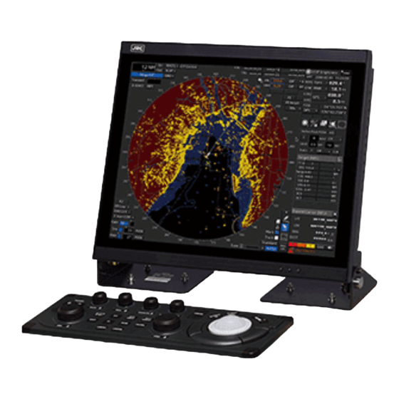
- Page 28 NWZ-214 19inch Display NWZ-208 26inch Display NQE-3167 NQE-3141-4A Power Control Unit (Option) Interswitch Unit (Option) NQE-3141-8A NQE-1143 Junction Box Interswitch Unit (Option) xxvi...
- Page 29 Glossary Admiralty Information Overlay published by United Kingdom Hydrographic Office (UKHO). Automatic Identification System Acquisition/Activation zone Anti-clutter rain Rain/snow clutter suppression Anti-clutter sea Sea clutter suppression AZImuth stabilisation mode BCR/BCT Bow Crossing Range/Bow Crossing Time Chart Maintenance Software to manage the charts. Imports and updates the charts. C-MAP MAX* Digital chart data by C-MAP Course To Steer.
- Page 30 Long Pulse Marine Equipment Directive. Request standard for standardisation of marine equipment within the EU region The formal name is Multi Function Display. The navigation support functions such as RADAR, ECDIS, CID, and AMS can be executed by switching. MMSI Maritime Mobile Service Identity Man Over Board Performance MONitor...
- Page 31 True Motion. A display across which the own ship and targets move with their own true motions. To WPT To Waypoint (To WPT) Trails Tracks displayed by the radar echoes of targets in the form of an afterglow Trial manoeuvre A graphical simulation facility used to assist the operator to perform a proposed manoeuvre for navigation and collision avoidance purposes True vector...
- Page 32 Pulse compression Correlation processing performed when a transmitted chirp signal is received by a solid-state radar after reflecting off the target. This processing gain enables the radar to have necessary detection capability even when a transmission power is low. Radar beacon A navigation aid which responds to the radar transmission and generates radio wave Range...
- Page 33 Notations Operation notations Trackball operations on the operation panel are expressed as follows. Operation Notation Click the left button. Click Example: Click on the object. Double-click the left button. Double-click Example: Determine the drawing by double-click. Click the right button Click the right mouse button Example: Display the context menu by clicking the right mouse button.
-
Page 35: Table Of Contents
Contents PREFACE ........................i Pictorial Indication ....................xi Precautions upont Equipment Operation ............xii Section 1 Overview ..................1-1 Functions ......................... 1-2 Features........................... 1-3 Components........................1-6 Structure ......................... 1-11 General System Diagrams ....................1-33 Section 2 Name and Function of Each Unit ..........2-1 Name and Main Function of the Operation Unit .............. - Page 36 2.3.1.6 Wind/Current Block ...................2-23 2.3.1.7 Conning ......................2-24 2.3.2 Information reference windows ................2-25 2.3.2.1 Switching between a standard window and an extended window .......2-25 2.3.2.2 AIS MSG Tray ....................2-25 2.3.2.3 NAVTEX......................2-26 2.3.2.4 Active Alert ......................2-28 2.3.2.5 Alert History ......................2-28 2.3.2.6 AIS ........................2-28 Section 3 Common Basic Operations ................
- Page 37 3.11.1.1 Starting mouseover display................3-18 3.11.1.2 Terminating mouseover display .................3-18 3.11.2 How to read mouseover display ................3-19 3.12 MOB (Man Over Board)....................3-20 3.13 Electronic Bearing Line (EBL) and Variable Range Marker (VRM) ........3-21 3.13.1 Electronic Bearing Line (EBL) and Variable range marker (VRM) ......3-21 3.13.2 Displaying the EBL and VRM buttons ..............3-22 3.13.3 Basic manipulation of EBL/VRM ................3-22 3.13.3.1 Switching the control right of EBL/VRM .............3-22...
- Page 38 3.20 Setting a Date and a Time (Calendar Operation) .............3-40 3.20.1 Details and usage of a calendar picker and a time picker .........3-40 3.20.1.1 Details of a calendar ..................3-40 3.21 Help ..........................3-41 3.22 Password Input .......................3-42 3.23 Managing Files with File Manager ...................3-43 3.23.1 File management ....................3-43 3.23.1.1 Copying a file ....................3-44 3.23.1.2 Deleting a file ....................3-44...
- Page 39 4.6.2.1 Displaying parallel index lines by using the [PI] button on the screen ....4-13 4.6.2.2 Displaying parallel index lines by using the [PI] key on the operation unit ...4-14 4.6.2.3 Description of the [PI Menu] dialogue ..............4-14 4.6.3 Setting all the parallel index lines concurrently (All mode) ........4-16 4.6.3.1 Changing the bearing/interval of parallel index lines in the operation unit (All mode) .......................4-17 4.6.4...
- Page 40 5.3.7 Adjusting to optimal images (Selection of observation scenes)......... 5-11 General Radar Operation ....................5-13 5.4.1 Interference Rejection (IR function) .................5-13 5.4.2 Changing the transmitter pulse length ..............5-14 5.4.3 Enhancing targets ....................5-15 5.4.4 Using video processing (Echo Process) ..............5-16 5.4.5 Setting the azimuth mode ..................5-17 5.4.6 Setting a motion mode.....................5-19 5.4.6.1 Resetting own ship to its initial position in [TM] (True Motion display) mode ..5-20...
- Page 41 6.4.2 Setting vector ......................6-14 6.4.2.1 Vector modes ....................6-14 6.4.2.2 Setting vector mode ..................6-15 6.4.2.3 Vector length (Vector time) ................6-16 6.4.2.4 Setting the vector length ..................6-16 6.4.3 Setting collision decision criteria ................6-16 6.4.3.1 Setting CPA limit ....................6-17 6.4.3.2 Setting TCPA limit....................6-17 6.4.4 Showing the CPA ring ....................6-17 Setting and operating target tracking ................6-18...
- Page 42 6.7.2 Alarm for new target acquired in automatic acquisition guard zone (New target) ..6-41 6.7.3 Lost target notification (Lost)..................6-42 6.7.4 Target Tracking function alarm (TT Data) ..............6-43 6.7.5 Gyro set notification (Set Gyro) ................6-43 Track Function ........................6-44 6.8.1 Setting the past position ..................6-44 6.8.2 Setting the other ship's tracks ..................6-45 6.8.2.1 Setting track colour ...................6-45...
- Page 43 7.4.3 False echo by secondary reflection ................7-8 7.4.4 False echo by multiple reflection ................7-8 7.4.5 Second time echoes ....................7-9 7.4.6 Radar interference....................7-9 Radar Transponder (SART) Screen Display..............7-10 Display of AIS-SART .......................7-12 7.6.1 Radar screen display example .................7-12 7.6.2 Numeric data display example .................7-12 Section 8...
- Page 44 Section 10 Creating a User Map ..............10-1 10.1 Display the "User Map" menu ..................10-2 10.2 Creating/Editing a User Map ....................10-3 10.2.1 Displaying the File Operation dialogue ..............10-4 10.2.1.1 [File Operation] dialogue ...................10-4 10.2.2 Creating a new user map..................10-5 10.2.3 Editing the existing user map ...................10-5 10.2.3.1 Editing the user map that is currently displayed ..........10-5 10.2.4 Displaying a user map .....................10-5 10.2.5 Operating a user map file ..................10-6...
- Page 45 10.6.3.2 Creating a text with EBL/VRM operation ............10-21 10.6.3.3 Editing a text ....................10-21 10.6.3.4 Editing a template ...................10-22 10.6.3.5 Changing a text angle ..................10-22 Section 11 Setting up Screen View ...............11-1 11.1 Setting Screen Display Options ..................11-1 11.1.1 Setting up the display of own ship symbol ..............11-2 11.1.2 Setting up the display of own ship’s tracks ...............
- Page 46 13.4 Observation Scene Common Settings ................13-8 13.5 Setting Other Ship’s Radar Trails ..................13-9 13.6 Setting Radar Trail Mask ....................13-10 13.7 Setting Radar Antennas....................13-12 13.8 Setting Associations ......................13-13 13.9 Setting Own Ship's Dynamic Trait ..................13-14 13.10 Setting Consort Ship Preset ..................13-15 13.11 Setting Operation Tests ....................13-16 13.12 Setting AIS Filters ......................13-17 13.13 Setting the Target Track Function to ON/OFF ..............13-19...
- Page 47 14.2.3.3 Adjusting a performance monitor of a magnetron radar (NKE-2255) ....14-8 14.2.3.4 Adjusting a performance monitor of a Solid State Radar (NKE-1632/2632) ..14-9 14.2.4 Setting sector blank ....................14-10 14.2.4.1 Setting sector blank ..................14-10 14.2.5 Adjusting the TT function ..................14-11 14.2.5.1 Setting vector constants ..................
- Page 48 15.1.6 Setting and confirming the sensor source ..............15-5 15.1.6.1 Setting the sensor source ..................15-5 15.1.6.2 Checking the sensor source status ..............15-6 15.2 General Maintenance ......................15-7 15.3 Maintenance on Each Unit ....................15-8 15.3.1 Radar antenna NKE-1130/1632/2632/2103/2255 .............15-8 15.3.1.1 Precautions in mounting the cover ..............15-9 15.3.1.2 Radiator ......................15-10 15.3.1.3 Rotating section ....................15-10 15.3.2 Display unit ......................15-10...
- Page 49 17.1 About Disposal of This Equipment ...................17-1 17.2 About Disposal of Used Magnetrons ................17-1 17.3 Chinese Version RoHS ....................17-2 Section 18 Specifications ................18-1 18.1 JMR-5410-4X ........................18-1 18.2 JMR-5410-6X ........................18-2 18.3 JMR-5410-6XH .......................18-3 18.4 JMR-5425-7X ........................18-4 18.5 JMR-5425-9X ........................18-5 18.6 JMR-5425-6XH .......................18-6...
- Page 50 18.22 Process Unit........................18-23 18.23 Standard Operation Unit ....................18-24 18.24 Trackball Operation Unit ....................18-25 18.25 Keyboard Operation Unit ....................18-25 18.26 19inch Display .......................18-26 18.27 26inch Display .......................18-27 18.28 Sensor LAN Switch Unit ....................18-28 18.29 Junction Box .........................18-28 Appendix A Radar Antenna / Display Unit Block Diagrams ......A-1 Radar Antenna Block Diagrams ..................
- Page 51 C.3.3 Precautions during a slave connection ..............C-8 C.3.4 Setting during installation..................C-9 Appendix D Menu List and Materials ..............D-1 D.1 Menu List ..........................D-1 D.1.1 Anchor Watch ......................D-1 D.1.2 Chart ........................... D-1 D.1.3 User Map ........................D-2 D.1.4 TT/AIS .........................
- Page 52 D.2.5 NAVTEX ........................D-38 D.2.5.1 NAVTEX ......................D-38 D.2.6 User Map ........................D-39 D.2.6.1 Mark ........................D-39 D.2.6.2 Line (Start point・End point) ................D-39 D.2.6.3 Line (Midpoint) ....................D-39 D.2.6.4 Line (Line segment) ................... D-40 D.2.6.5 Line (Select all) ....................D-40 D.2.6.6 Text ........................
-
Page 53: Overview
Section 1 Overview In case water or a metal object gets inside the equipment, turn off the power immediately, unplug the power supply cable from an electric outlet, and contact our head office, or a nearby branch or local office to request servicing. Keeping the equipment in operation under such condition may cause a fire, an electric shock or a malfunction. -
Page 54: Functions
Target tracking functions (manual/automatic target acquisition and tracking, vector and trail displays and alarm displays) • 8-unit switchover (Interswitch) function (option) • Chart display function (option) *1: The following databases can be displayed. JRC ROM card cannot use. - C-MAP MAX - newpec Section 1 Overview... -
Page 55: Features
Features This equipment has the following features: Utilization of an icon menu Intuitive operation system based on the workflow High-resolution large screen Message reception notification function Notifies arrival of a new AIS message and so on with a badge. Utilization of a common information window Enables display of target information and simple conning information (wind direction/wind speed information, etc.) with a simple switching operation. - Page 56 Target tracking (TT) function by utilizing the latest technology By using the latest high-speed DSP and tracking algorithm, the target acquisition/tracking performance is improved, achieving stable operation for target tracking inside of clutters also. - Capable of acquiring and tracking up to 100 targets by using an optional component (30 targets can be acquired/tracked as standard) - Expressing danger status with a sound and shape and colour of a symbol - Equipped with a trial manoeuvring function...
- Page 57 Performance monitor function This function monitors radar performance (transmission output and reception sensitivity) on the screen. Interswitch function (Option) By connecting to the interswitch unit (optional), up to 8 radars can be inter-switched with simple operations. (To use the interswitch function, an interswitch unit independent of the display unit and a cable for connecting each display unit are required.) 付録...
-
Page 58: Components
Components A list of components and optional accessories is shown below. Components of the Display Unit Unit Type name Q'ty Remarks 26inch LCD Monitor Both AC and NWZ-208 Standard equipment. DC inputs supported LCD Monitor Equipped with one of 19inch LCD Monitor DC input NWZ-214 the three monitors. - Page 59 Unit Type name Q'ty Remarks NQE-1143 Option Junction Box Serial LAN Interface Circuit CMH-2370 NQA-2443 Option SENSOR LAN 16P SW HUB CQL-221 Switch NQA-2443 components Sensor LAN Switch Interconnection CML-841 For 26-inch 26-inch Desktop Stand CWB-1660 monitor Option Monitor Stand For 19-inch 19-inch Desktop Stand CWB-1659...
- Page 60 Unit Type name Q'ty Remarks F2:S4-5AN1 (5ZFCA00050) 7ZXRD0026 One box is packed in F3:ST6-10AN1 the package (3 pieces (5ZFCA00053) NDC-1678 each). Processing Unit Either ZXRD0026 or Fuse (F2/F3) 7ZXRD0015 is F2:ST6-10AN1 included according to (5ZFCA00053) Spare Parts the general type name. 7ZXRD0015 F3:ST6-10AN1 (5ZFCA00053)
- Page 61 Equipment composition and Ship’s mains General type Radar Performance Display Display Ship’s mains name antenna monitor unit JMR-5410-4X NKE-2103-4 NJU-85 19inch NCM-963 24VDC NWZ-214/ JMR-5410-6X NKE-2103-6 NJU-85 NCM-963 24VDC NWZ-214-AC JMR-5410-6XH NKE-2103-6HS NJU-85 NCM-963 24VDC JMR-5425-9X NKE-2255-9 NJU-97 NCM-963 24VDC...
- Page 62 Option list of radar antennas Name Model name Remarks NJU-84 For S-band radars excluding NKE-1632, 2632 and 2632-H Performance monitor NJU-85 For NKE-2103 NJU-97 For NKE-2255 (Built-In) 4-unit switching ISW NQE-3141-4A Separate unit 8-unit switching ISW NQE-3141-8A Separate unit (special order) Power control unit NQE-3167 Separate unit...
-
Page 63: Structure
Structure The dimensional outline drawing of this equipment is shown below. 付録 Outline Drawing of Radar Antenna (NKE-1130) 1-11 Section 1 Overview... - Page 64 Outline Drawing of Radar Antenna (NKE-1632) Section 1 Overview 1-12...
- Page 65 Outline Drawing of Radar Antenna (NKE-2632) 付録 1-13 Section 1 Overview...
- Page 66 Outline Drawing of Radar Antenna (NKE-2632-H) Section 1 Overview 1-14...
- Page 67 Outline Drawing of Radar Antenna (NKE-2103-4) 付録 1-15 Section 1 Overview...
- Page 68 Outline Drawing of Radar Antenna (NKE-2103-6/6HS) Section 1 Overview 1-16...
- Page 69 Outline Drawing of Radar Antenna (NKE-2255-7) 付録 1-17 Section 1 Overview...
- Page 70 Outline Drawing of Radar Antenna (NKE-2255-9) Section 1 Overview 1-18...
- Page 71 Outline Drawing of Radar Antenna (NKE-2255-6HS) 付録 1-19 Section 1 Overview...
- Page 72 Outline drawing of 26inch Display (NWZ-208) Section 1 Overview 1-20...
- Page 73 Outline drawing of 19inch Display (NWZ-214) 付録 1-21 Section 1 Overview...
- Page 74 Outline drawing of 19inch Display (NWZ-214-AC) Section 1 Overview 1-22...
- Page 75 Outline Drawing of Process Unit (NDC-1678) 付録 1-23 Section 1 Overview...
- Page 76 Outline Drawing of Standard Operation Unit (NCE-5794) Section 1 Overview 1-24...
- Page 77 Outline Drawing of Trackball Operation Unit (NCE-5605) (Option) 付録 1-25 Section 1 Overview...
- Page 78 Outline Drawing of Keyboard Operation Unit (NCE-5625) (Option) Section 1 Overview 1-26...
- Page 79 Outline Drawing of Junction Box (NQE-1143) 付録 1-27 Section 1 Overview...
- Page 80 Outline Drawing of 26inch Desktop Frame (CWB-1660) Section 1 Overview 1-28...
- Page 81 Outline Drawing of 19inch Desktop Frame (CWB-1659) 付録 1-29 Section 1 Overview...
- Page 82 Outline Drawing of Interswitch Unit (NQE-3141-4A) (Option) Section 1 Overview 1-30...
- Page 83 Outline Drawing of Interswitch Unit (NQE-3141-8A) (Option) 付録 1-31 Section 1 Overview...
- Page 84 Outline Drawing of Power Control Unit (NQE-3167) (Option) Section 1 Overview 1-32...
-
Page 85: General System Diagrams
General System Diagrams Connection examples of this equipment are shown below. General System Diagram of JMR-5410-4X/6X/6XH 付録 1-33 Section 1 Overview... - Page 86 General System Diagram of JMR-5425-7X/9X/6XH Section 1 Overview 1-34...
- Page 87 General System Diagram of JMR-5430-S 付録 1-35 Section 1 Overview...
- Page 88 General System Diagram of JMR-5472-S Section 1 Overview 1-36...
- Page 89 General System Diagram of JMR-5482-S/SH 付録 1-37 Section 1 Overview...
-
Page 91: Name And Function Of Each Unit
Section 2 Name and Function of Each Unit Name and Main Function of the Operation Unit 2.1.1 Standard operation unit [13] [14] [15] [16] [10] [11] [17] [18] [12] [24] [21] [22] [19] [20] [23] [25] When turning off the power supply, do not hold down the power button of the operation unit. - Page 92 Name Function outline [EBL] dial When this dial is turned, control moves in the EBL (PI) direction with control right. This dial also moves the cursor horizontally (in cursor move mode). [VRM] dial When this dial is turned, control moves in the VRM (PI) direction with control right. This dial also moves the cursor vertically (in cursor move mode).
-
Page 93: Display Unit
2.1.2 Display unit [Brightness Adjustment] [Power] button buttons [Power] button When the Power button is pressed while the power of the display unit is turned off, the power is turned on. To turn off the power of the display unit, press the Power button for 5 seconds or longer. [Brightness Adjustment] buttons These buttons are used to adjust the brightness of the screen. -
Page 94: Names And Main Functions Of The Mode Screen Common Sections
Names and Main Functions of the Mode Screen Common Sections This section describes the name of each section of the mode screen and the main functions. Refer to “2.2.12 Radar system information” Refer to “2.2.10 Range Refer to “2.2.9 Navigation Refer to “2.2.2 Key assignment and mode information”... -
Page 95: Key Assignment Indication Area
2.2.2 Key assignment indication area When the [MULTI] dial is turned, the assigned functions are operated. For the function assignment, refer to "3.18 [Multi] dial". 2.2.3 Own ship information Do not use the offset function during navigation. If the equipment is used with the offset value entered as the own ship position (deviated from the actual position), accidents may result. - Page 96 UTC/Local date and time This button displays the current date and time. • When the button is clicked on, the time can be switched to the UTC time display or Local time display. • [Maintenance] - Set the time format by selecting [Date/Time/Time Zone]-[Display Style] on the menu.
- Page 97 See the previous page. POSN Displays the POSN information. [1] The data name of POSN is displayed. [2] The sensor source of POSN is displayed. Select a sensor source in the [Source] combo box. Any of the following sensor sources can be selected. When [Menu] is selected, the [Sensor Selection/Status] dialogue is displayed.
-
Page 98: Other Ship Information
2.2.4 Other ship information [AIS] button This button sets the AIS function to On/Off. Off: Memo When AIS is set to Off, alerts relating to AIS are also no longer displayed. [Filter] button When the cursor is placed on this button while AIS is On, the AIS Filter status is displayed. -
Page 99: Right Toolbar
2.2.5 Right toolbar The functions of the buttons of the right toolbar are as follows. Message notification button Day/Night button When this button is clicked on, the dialogue relating to the latest The display colour on the screen can be notification message is displayed among the AIS message tray switched to 5 levels according to the and NAVTEX reception information. -
Page 100: Toolbar
2.2.6 Toolbar The function of each button on the toolbar is described below. Out of the buttons on the toolbar, some are shown and the others are hidden in normal cases. Click on the Disclosure button to switch the display. Normal display Normal non-display Disclosure... -
Page 101: Buttons That Are Normally Displayed
2.2.6.1 Buttons that are normally displayed [AUTO] (Cursor mode selection) button PEN (Write tool) button When this button is clicked on, the cursor When this button is clicked on at user map mode is switched to the AUTO mode. creation, the mode is changed to the user For the details of the cursor mode, refer to map operation mode. -
Page 102: Alert Notification Area
2.2.7 Alert notification area When an alert occurs, the alert status, the contents of the alert and the occurrence count are displayed in the alert notification area. For the details, refer to "3.7 Confirming and Acknowledging an Alert". 2.2.8 Other Common Area SD Card Removal button Icon Status... -
Page 103: Navigation Tools
2.2.9 Navigation tools The tools that are used for measurement are displayed. Cursor information display area When the cursor is set on a target, the cursor information is displayed. For the details, refer to "4.3 Using the Cross-hair Cursor". EBL/VRM operation button area Use this button to operate EBL/VRM. -
Page 104: Radar Signal Information
2.2.11 Radar signal information [×2] (Double scale display) button When this button is clicked on, the double scale zoom function is switched to On/Off. For the details, refer to "5.4.10 Doubling the size of radar image". [IR] combo box This setting is enabled to set a radar interference rejection function from the list For the details, refer to "5.4.1 Interference Rejection (IR Function)". -
Page 105: Radar System Information
2.2.12 Radar system information On this window, verify, adjust, and set a signal tuning status. The display varies according to the radar antenna type. Standby/transmission Tuning status confirmation switching button bar display Whenever this button is Displays the tuning indication clicked on, the mode is value from the transceiver. -
Page 106: Display Inside The Ppi
2.2.13 Display inside the PPI TT target symbol Automatic acquisition/ activation zone Association Ship's heading target marker Ship's heading line TT target number Radar trails Past position VRM1 AIS target symbol AIS target number AIS target vector VRM2 EBL1 Other ship's EBL2 track Own ship's symbol... -
Page 107: Common Information Window
Common Information Window The information that is displayed on the Common Information Window is classified into two major types: information monitoring and information referencing. An information monitoring window is used together with radar PPI and a chart, and the information includes TT/AIS value information, conning blocks, etc. -
Page 108: Information Monitor Windows
2.3.1 Information monitor windows Information monitoring related windows is as follows. Item Contents Related section Target INFO TT/AIS movement information 2.3.1.1 Target INFO TT List TT target risk sequence list 2.3.1.2 TT List AIS List AIS target risk sequence list 2.3.1.3 AIS List Detail information relating one AIS AIS Detail INFO... - Page 109 AIS information • AIS information of the target is displayed. • When the (AIS standard/extension switching) button is clicked on, the display is switched between the standard display and the extended display. • The following information items are displayed. Displayed information Explanation AIS ID Displays an AIS target ID numbers (1 to 180).
-
Page 110: Tt List
AIS SART information AIS SART information is displayed by using an extended display. Unlike the AIS information extended display, the following items are not displayed. • Call Sign • Destination • (AIS standard/extension switching) button 2.3.1.2 TT List A TT List lists the degrees of risks of TT targets. For the details, refer to "6.14.1 TT list". - Page 111 Displayed information Explanation ETA or UTC Displays the expected arrival time of an AIS target. Navigation Status Displays the navigation conditions of an AIS target. 0: Under Way Using Engine 1: At Anchor 2: Not Under Command 3: Restricted Manoeuvrability 4: Constrained by Her Draught 5: Moored 6: Aground...
- Page 112 Displayed information Explanation Cargo Category When the setting of the type of a ship is 2X, 4X, 6X, 7X, 8X or 9X, the digit shown at the end of the code represents the cargo/condition. X1 Category X(DG/HS/MP) X2 Category Y(DG/HS/MP) X3 Category Z(DG/HS/MP) X4 Category OS(DG/HS/MP) X9 No Additional Information...
-
Page 113: 2Nd Ppi
2.3.1.5 2nd PPI The setting items are the same as those of the main PPI setting except for the setting items that can be specifically set under 2nd PPI. For the details, refer to "2.2.10 Range and mode information". Memo •... -
Page 114: Conning
2.3.1.7 Conning The Conning shows simple conning information. Click [Conning] on the [Page Selection] dialogue box. When [Conning] is not displayed, drag the scroll bar downwards. The [Conning] window is displayed. One pane is available and the pane is provided with a window switching button Click a window switching button to show the [Contents Selection] window. -
Page 115: Information Reference Windows
2.3.2 Information reference windows By clicking on the buttons in the window, the contents that are displayed in the window can be switched. Information reference related windows are listed below. Button Displayed content Related section [AIS MSG Tray] AIS message tray 2.3.2.2 AIS MSG Tray 2.3.2.3 NAVTEX [NAVTEX]... -
Page 116: Navtex
2.3.2.3 NAVTEX The NAVTEX message is displayed. This equipment supports the NAVTEX messages of the NMEA format and NAVTEX format. The format that is used for displaying the NAVTEX messages is determined by the installation. A NAVTEX message list is displayed on the left side of the pane and the details of the message are displayed on the right side. - Page 117 (3) [Delete] dialogue Displayed item Explanation Selected Message When this item is selected, the message that was selected from the NAVTEX message list is targeted for deletion. Before When this item is selected, a calendar picker is displayed. Messages on and before the date that is specified by the calendar picker are targeted for deletion.
-
Page 118: Active Alert
2.3.2.4 Active Alert This window displays active alerts that occurred in this equipment. For the details, refer to "3.7.4 Displaying active alert and alert history". 2.3.2.5 Alert History This window displays the history of alerts that occurred in this equipment. For the details, refer to "3.7.4 Displaying active alert and alert history". -
Page 119: Section 3 Common Basic Operations
Section 3 Common Basic Operations Powering On and Starting Turn on the power supply according to the following procedure. Press the Power button on the operation unit. Power button Start-up screen is displayed. After the start-up screen is displayed, the Mode Selection screen is displayed after a brief interval. -
Page 120: Basic Operations When Using A Trackball
Basic Operations When Using a Trackball A trackball in the operation unit is mainly used for the operations of this equipment. This section describes the basic operations performed using the trackball. 3.3.1 Basic trackball operations As the basic trackball operations, move the cursor that is displayed on the screen and perform various operations using the left and right mouse buttons. -
Page 121: Displaying Simplified Information And Operational Guide Of Objects
3.3.3 Displaying simplified information and operational guide of objects When the cursor is set to a specific object, the "simplified information" and "operational guide" are displayed. Simplified information Operational guide When the cursor is moved, the display is cleared. 3.3.4 Cursor types The following cursors are displayed by this equipment. - Page 122 Cursor Cursor Name Description Arrow cursors Appear when any of the following operations is performed. • EBL/VRM, AIS filter, AZ, PI • User map • Moving the multi-view bar • Operation of EBL, VRM Rotation cursor Appears at PI operation. Eraser cursor Appears in eraser tool mode.
-
Page 123: Basic Menu Operations
Basic Menu Operations Various functions can be executed or set from the menu that is displayed by clicking on the [Menu] button. This section describes the basic menu operations. 3.4.1 Opening the menu Click on the [Menu] button at the top-right corner of the top screen. [Menu] button The menu is displayed. -
Page 124: Menu List
Some functions comprise a classification pane and an edit pane and a dialogue is available to hide the classification pane by using the Disclosure button. Example: [Settings] is clicked on the menu. Disclosure button Hiding the classification pane Classification pane Edit pane Memo When the RADAR transmission status is Transmit and Classification is selected, the classification... -
Page 125: Basic Dialogue Box Operations
Basic Dialogue Box Operations When a dialogue box is opened, the dialogue box is in the factory setting state or state at termination of the previous operation. The setting can be changed by the following operation. • Enter a character or a value in the input box. •... -
Page 126: Closing A Dialogue Box
A function may also be set by opening another dialogue box from the dialogue box. [File operation] dialogue box display button: When this button is clicked on, the [File operation] dialogue box is opened. 3.5.2 Closing a dialogue box Close the dialogue box by clicking on the [X] (Close) button on the dialogue box. [X] button Section 3 Common Basic Operations... -
Page 127: Title Bar
3.5.3 Title Bar The name (title) of the dialogue box is displayed on the title bar of the dialogue box. Title of the dialogue The dialogue can be moved by dragging the title bar. When moving the dialogue, move to the position that does not cover the PPI area. If the dialogue covers the PPI area, it may interrupt the recognition of the display information. -
Page 128: Operation Of The Information Monitor Window
Operation of the Information Monitor Window This section describes the operation and editing of the information monitor window. For the details of the information monitor window, refer to "2.3 Common Information Window". 3.6.1 Opening the information monitor window Click on the page switching button on the initial display window. In the initial display, a blank window appears. -
Page 129: Confirming And Acknowledging An Alert
Confirming and Acknowledging an Alert Information is displayed in addition to a warning or a caution in the alert status area. Information is used to report operation errors and so on to the users. Unlike other alerts, no detail display is provided for Information. When an alert occurs, a buzzer sound is emitted and an alert balloon is displayed in the alert notification area. -
Page 130: Stopping A Buzzer
3.7.1 Stopping a buzzer To stop a buzzer (silencing), click the silence button in the alert notification area or press the [SILENCE] key in the operation unit. [SILENCE] key Silence button 3.7.2 Confirming alert contents When an alert is generated, the alert message is displayed in the "Alert status area". The alert type and the number of alerts are displayed by the button. -
Page 131: Acknowledging The Alert
3.7.3 Acknowledging the alert After the [ACK] (acknowledgement) button of the alert detail display dialogue box is clicked on or the [ALERT ACK] (alert acknowledgement) key of the operation section is pressed after verification of the alert contents, the alert that is currently displayed is acknowledged. When there are multiple alerts, perform the same operation by displaying the details dialogue box of another alert. - Page 132 [3] Active alert list • The alert of the highest priority is automatically selected. When an alert in the active alert list is clicked on, the alert is selected. • The details of the selected alert are displayed in "[4] Details of active alert". •...
-
Page 133: Switching The Day/Night Mode
Switching the Day/Night Mode Change of the colour of the Day/Night button, particularly the use of the [Night] colour, may interfere with the recognition of display information. Confirm display information can be recognised. The screen display colour can be switched to any of five levels according to the brightness within the bridge. -
Page 134: Adjusting The Brightness Of The Screen And Operation Unit
Adjusting the Brightness of the Screen and Operation Unit The brightness of the screen can be adjusted within the range from 0 to 100 and the brightness of the operation unit can be adjusted within five levels (0 to 4). Click on the [Display and Panel Brightness] button on the right toolbar. -
Page 135: Switching The Mode
3.10 Switching the Mode Switch the mode between the radar mode and the synthesis mode. Click on the mode switching button on the right tool bar. Whenever the button is clicked on, the mode switches repeatedly as [Radar mode] → [Synthesis mode] →... -
Page 136: Mouseover Display
3.11 Mouseover Display When the mouse cursor is hovered over an object on the screen, the information on the object is displayed on a popup window near the cursor. When objects overlap, the following priority is applied and information on the object of the higher priority is displayed. -
Page 137: How To Read Mouseover Display
3.11.2 How to read mouseover display As a mouseover display example, the following information is displayed in mouseover display of AIS targets/tracking targets. The width and height of the popup window changes according to the number of characters that are displayed. -
Page 138: Mob (Man Over Board)
3.12 MOB (Man Over Board) When a person falls overboard, this monitoring function prevents loss of sight of the position of the person overboard. The MOB use procedure is as follows. Click on the MOB button on the right toolbar. The [Marker] dialogue box appears and the MOB marker is displayed on the own ship’s position when the button is clicked on. -
Page 139: Electronic Bearing Line (Ebl) And Variable Range Marker (Vrm)
3.13 Electronic Bearing Line (EBL) and Variable Range Marker (VRM) 3.13.1 Electronic Bearing Line (EBL) and Variable range marker (VRM) The electronic bearing line (EBL) and the variable range marker (VRM) are the essential tools for measuring bearings and ranges. This equipment is equipped with two sets each for EBL (EBL1/EBL2) and VRM (VRM1/VRM2). -
Page 140: Displaying The Ebl And Vrm Buttons
3.13.2 Displaying the EBL and VRM buttons Use the EBL/VRM button for creation and setting of EBL/VRM and bearing/range of EBL/VRM. The EBL/VRM button is always displayed on measuring tools at the upper right corner of the screen. EBL button (Left: EBL1, Right: EBL2) VRM button (Left: VRM1, Right: VRM2) Memo The display mode of EBL/VRM that is displayed on the dialogue by selecting [View] - [Tools] on the... -
Page 141: Setting Up The Measurement Starting Points
3.13.3.2 Setting up the measurement starting points The measurement starting points of the EBL/VRM in operation can be changed. Set up the measurement starting points as usage. Enable the manipulation of EBL/VRM by clicking on the EBL/VRM button. The display of the clicked button changes from [Off] to the bearing presentation of the measurement starting point. -
Page 142: Setting Up The Range Unit Of Vrm
3.13.3.4 Setting up the range unit of VRM Click on the VRM Range Unit button. Each time the button is clicked on, display switches in the order of [NM] → [sm] → [km] → [NM] [NM]: Displays the range in the unit of NM. [sm]: Displays the range in the unit of sm. -
Page 143: Rectangle Cursor
3.14 Rectangle Cursor The rectangle cursor is a symbol imitating the shape of a net with the assumption of the use in trawl fishing. [Operation procedure] Use the following menu operation to open the setup screen of the rectangle cursor. [Menu] button →... - Page 144 Setting item Contents Setting value Rotation In rectangle cursor edit mode, rotate the rectangle 0.0 to 359.9° cursor by using the [MULTI] dial. Turn clockwise: +, Turn anti-clockwise: - It is possible to set from the numeric value input keyboard by selecting an input box. Length of One Side Displays the length of one side of the rectangle Maximum value...
-
Page 145: Cursor Auto Mode
3.15 Cursor AUTO Mode The cursor AUTO mode (referred to as AUTO mode henceforth) is a function that automatically executes the function (operation) that is assigned to the object when the object under the cursor is clicked on. The AUTO mode is effective for the following objects. Section that describes the function (operation) to Object be executed... -
Page 146: Ais
3.15.2 AIS [Sleeping AIS target target] When a sleeping AIS target is clicked on, the AIS target is activated. [Activated AIS target] When an Activated AIS target is clicked on, the AIS target value is displayed. [Numeric displayed AIS target] When the numeric displayed AIS target is clicked on, the AIS target value display is cancelled. -
Page 147: Az) Acquisition/Activation Zone
3.15.3 TT [TT target] When TT target is clicked on, a numeric value is displayed. [Numeric displayed TT target] When a numeric displayed TT target is clicked on, the numeric value display of TT is cancelled. 3.15.4 (AZ) Acquisition/Activation Zone End Distance Start Angle End Angle... -
Page 148: Ais Filter
3.15.5 AIS filter Sector Sector (Start angle) (End angle) * The section other than the sides of the sector is not Own ship targeted for selection. Ring [Sector (start angle)] When Sector (start angle) is clicked on, the cursor is set to the Sector (start/end angle) change mode. [Sector (end angle)] When Sector (end angle) is clicked on, the cursor is set to the Sector (end angle) change mode. -
Page 149: Selected Object
3.15.6.2 Selected object The operation varies according to the object. (1) Mark When the selected mark is clicked on, a mark move mode is set. When you right-click, the mark move mode is cancelled. (2) Line Line in the selected state Vertex Line in the non-selected state [Selecting vertex]... -
Page 150: Ebl
[Moving a vertex] When the middle point of line in the selected state is clicked on, vertex move mode of line is set. [Inserting a vertex] When a line segment of line in the selected state is clicked on, vertex insertion mode of line is set. Memo A vertex can also be inserted by using [Insert Vertex] on the context menu that is displayed by right-clicking on the line in the selected state. -
Page 151: Monitoring Dragging Anchor
3.15.11 Monitoring dragging anchor 3.15.11.1 Object in the unselected state When a monitoring dragging anchor object is clicked on, the clicked object is set to the selected state and the [Anchor Watch] dialogue box is displayed. 3.15.11.2 Selected state Dragging anchor monitoring circle [Moving a dragging anchor monitoring circle] When a circumference of a dragging anchor monitoring circle in the selected state is clicked on, move mode of dragging anchor monitoring circle is set. -
Page 152: Saving The Screen That Is Currently Displayed
3.16 Saving the Screen That Is Currently Displayed The image that is displayed on the screen can be saved as a PNG file. Use the following procedure to save screen images. Click on the Disclosure button on the toolbar. Buttons normally hidden are displayed. Click on the screen capture button The screen that is currently displayed is saved and the next confirmation dialogue box is displayed. -
Page 153: Favourite" Registering Function
3.17 “Favourite” Registering Function By registering a frequently used menu as a favourite, the menu can be accessed quickly by selecting it from the list of favourites. 3.17.1 Registering/cancelling favourites An icon for registering favourites is available on the screen title bar of each menu. By selecting the icon, a menu can be registered as a favourite or registration can be cancelled. -
Page 154: Multi] Dial
3.18 [MULTI] Dial 3.18.1 Functions of [MULTI] dial By turning the [MULT] dial, the functions that are assigned to the [MULTI] dial can be operated. Assignment to the [MULTI] dial can be changed. 3.18.2 Functions assigned to [MULTI] dial 3.18.2.1 Displaying a screen for setting the function that is assigned By pressing the [MULTI] dial, the setting screen for the function that is currently assigned can be displayed. -
Page 155: Basic Operations Of The Software Keyboard
3.19 Basic Operations of the Software Keyboard Use a software keyboard for inputting numeric values and characters in various setting operations. This section describes the basic operations of a software keyboard. 3.19.1 Starting a software keyboard When the mouse button is clicked on a numeric input text box on such as a dialogue box, a numeric input software keyboard is displayed. - Page 156 [1] Input value display section Displays the value that is input/edited through the software keyboard. [2] Spin button • When the right spin button is clicked on, the minimum unit value that can be set is added to the value that is displayed. When the left spin button is clicked on, the minimum unit value that can be set is subtracted from the value that is displayed.
- Page 157 [9] [Enter] key Determines the input operation. [10] Input range display section (format display section) Displays the values and character types that can be input. [11] Numeric keys Use the keys for input of numeric values. [12] Arrow keys When there are multiple input parts, the active part can be moved to the left/right by clicking on the arrow key.
-
Page 158: Setting A Date And A Time (Calendar Operation)
3.20 Setting a Date and a Time (Calendar Operation) Set a date and a time on the calendar input screen. The following calendar types are available. • Calendar picker • Calendar picker + Time picker • From-To calendar picker + Time picker 3.20.1 Details and usage of a calendar picker and a time picker 3.20.1.1 Details of a calendar... -
Page 159: Help
3.21 Help Help information on the operation of this equipment can be displayed. [Operation procedure] Perform the following menu operation to open the Help screen. [Menu] button → Help For the details of installation of Help, refer to “15.7 Updating Help Data”. Memo The Preface, Section 1 and Appendix A are not displayed in the Help. -
Page 160: Password Input
3.22 Password Input Equipment settings are protected by a password. To open the dialogue box of the protected setting function, the password input is necessary. [Operation procedure] Perform the following menu operation to open the password input screen. [Menu] button → Code Input Enter "0"... -
Page 161: Managing Files With File Manager
3.23 Managing Files with File Manager Confirm computer virus does not exist in external storage media beforehand when reading and writing of the file by using external storage media. Influences other equipment when the display unit is infected with the virus, and it may cause a breakdown. -
Page 162: Copying A File
3.23.1.1 Copying a file This section describes file management by using the example copying a file in the file list of the drive that is specified in the [Drive] combo box on the left hand side of the dialogue box to the drive that is specified in the [Drive] combo box on the right hand side. -
Page 163: Loading And Saving Files
3.23.2 Loading and saving files The [File Load/Save] tab enables loading and saving files. The following table shows the items that are displayed by the [File Load/Save] tab. Item Contents File Type Select a file type. Either Own Track or Target Track can be selected. -
Page 164: Loading Files
3.23.2.1 Loading files Click on the [File Load/Save] tab. Select a file to be loaded. Memo Only one file can be selected each time. Select the file loading mode from the [Load Mode] combo box. Click on the [Load] button. A confirmation dialogue box appears. -
Page 165: Using A Key Macro
3.24 Using a Key Macro This function enables the recording of a key operation and by calling the recorded operation, automatic operation can be performed. 3.24.1 Recording a key macro A key operation can be recorded for each user key. Under the connection with the standard operation unit, up to two key macros can be recorded. -
Page 166: Operate Remotely The Marine Vhf Radiotelephone(Jhs-800S)
3.25 Operate remotely the Marine VHF Radiotelephone (JHS-800S) Channel settings and DSC call of VHF Radiotelephone (JHS-800S) can be operated from taskstation, it can be communicated from a distance place by wireless speaker microphone. ADDRESS(MMSI code) for DSC call of JHS-800S can be taken from AIS target on RADAR PPI. Note For more details of VHF Radiotelephone JHS-800S, please refer to instruction manual of JHS-800S. - Page 167 Select [VHF] in the classification pane. Select JHS-800S on the [Call Device] combo box for VHF communication. The JHS-800S connected to the radar can be selected from up to 3 equipment. APP A APP B 3-49 Section 3 Common Basic Operations...
-
Page 168: Display Vhf Radiotelephone Status From Menu-Bar
3.25.2 Display VHF Radiotelephone status from menu-bar For confirming/changing a JHS-800S communication channel, open the JHS-800S window from menu-bar. And also, DSC call is available on the window by input parameters such as ADDRESS (MMSI code). *It is not possible to operate the [VHF Call] window on the radar screen during operation of the JHS-800S. - Page 169 (10) (11) (12) (13) (1) Title bar Displays selected VHF Radiotelephone (JHS-800S). You can change it on [VHF] pane on the [Settings] dialog. (2) Output power Switches transmitting power between 25 W and 1 W. (3) [CH16] button CH16: Sets the radiotelephone to CH16 (or another priority channel). (4) Numeric key button for channel select Displays the numeric key pad (input 0 to 9) for selecting channels (figure on the right).
- Page 170 (8) [SCAN/DW/TW] On scanning, Indicates the current condition as follows. And its displayed only scanning mode. • Scanning • Dual Watch • During triple watch • During transmitting (9) [CH] Indicates the channel category as follows. • Priority channel such CH16, CH70 •...
-
Page 171: Dsc Call For Ais Target On Radar Ppi
3.25.3 DSC call for AIS target on RADAR PPI [VHF Call] dialog can be shown by right-click menu of AIS target on RADAR PPI. If the task station already received MMSI code of the AIS target, the MMSI code is shown on the [VHF Call] dialog. - Page 172 Click the [VHF Call] menu on the context menu. The [VHF Call] dialog is displayed. Click the [CALL] button on [VHF Call]. Selected VHF Radiotelephone (JHS-800S) will start DSC call. When calling the individual station, the communication can be started by the wireless speaker microphone after received the acknowledgement.
-
Page 173: Returning To The Mode Selection Screen By Terminating Operation
3.26 Returning to the Mode Selection Screen by Terminating Operation [Operation procedure] Perform the following menu operation to open the Password screen. [Menu] button → Code Input Enter 9999 and click on the [Enter] key. Control returns to the Mode Selection screen. 3.27 Terminating This Equipment When turning off the power supply, do not hold down the power button of the operation unit. -
Page 175: Range And Bearing Measurement Methods
Section 4 Range and Bearing Measurement Methods List of Measuring Tools This equipment is equipped with the following measuring tools to measure the range and bearing. Measuring tool Function Related section Cross-Hair Cursor Used to measure the range and bearing from 4.3 Using the Cross-hair (Cursor) the own ship’s position. -
Page 176: Target Position
Target Position The radar transmits the pulse-modulated radio waves. The transmitted waves are received in the target after being reflected (echoed). On the screen, the waves spread in the pulse width range direction based on the target position as the front edge. When measuring a target or setting a mark/line on the target, place the cursor on the front edge of the echo. -
Page 177: Using The Cross-Hair Cursor
Using the Cross-hair Cursor When moving the cursor into a window, it changes to a cross-hair cursor. With the cross-hair cursor, the bearing and position of a target can be measured. The information that is measured by the cursor is displayed in the cursor readout information area. 4.3.1 Displaying information in the cursor information readout area Display the cursor information by using the following procedure. -
Page 178: Measuring The Bearing And The Range From The Own Ship's Position To The Target By Using The Cross-Hair Cursor
4.3.2 Measuring the bearing and the range from the own ship’s position to the target by using the cross-hair cursor The measurement method is as follows. Memo When placing the cursor on the target, place the cursor on the front edge (towards the own ship of the echo) (CCRP side) of the echo. -
Page 179: Measuring By Using The Cursor Information That Is Displayed By Placing The
4.3.2.1 Measuring by using the cursor information that is displayed by placing the cursor inside of PPI Place the cursor on the target. When the cursor is placed on the target, the following cursor information is displayed. [1] TTG display and ETA display Displays TTG and ETA from the own ship’s position to the cursor position. -
Page 180: Setting A Reference Point
4.3.2.2 Setting a reference point Set a reference point by selecting the icon at the top right corner of the top screen. The following table shows the setting items. Setting item Description Icon displayed From Own Ship Own ship is used as the reference point. From Ref. -
Page 181: Using The Range Rings
Using the Range Rings Range rings are multiple concentric circles displayed on the PPI screen. Using range rings on the PPI screen, the range to a target can be measured by determining at which scale interval the target is positioned. The display of range rings can be turned on/off according to the following procedure. -
Page 182: Using The Electronic Bearing Line (Ebl) And Variable Range Marker (Vrm)
Using the Electronic Bearing Line (EBL) and Variable Range Marker (VRM) 4.5.1 Measuring a range and a bearing with EBL and 4.5.1.1 Measuring a range and a bearing with the trackball section of the operation unit When the cursor is in AUTO mode, EBL and VRM can be operated on the trackball section of the operation unit.This section describes the manipulation under EBL1 and VRM1;... -
Page 183: Measuring With The [Ebl] Or [Vrm] Dial On The Keyboard Operation Unit
45.0° Target EBL1 0.3NM CCRP VRM1 Bearing and range from the own ship's position to the target in this figure: True bearing 45.0° Range 0.30 NM 4.5.1.2 Measuring with the [EBL] or [VRM] dial on the keyboard operation unit Press the [EBL] dial. The context menu is displayed. - Page 184 45.0° Target EBL1 0.3NM CCRP VRM1 Bearing and range from the own ship's position to the target in this figure: True bearing 45.0° Range 0.30 NM To clear the EBL: Press the [EBL] dial. The context menu is displayed. By turning the dial, select either [EBL1 Hide] or [EBL2 Hide]. Press the [EBL] dial.
-
Page 185: Measuring Between Arbitrary Two Points
To clear the VRM: Press the [VRM] dial. The context menu is displayed. By turning the dial, select either [VRM1 Hide] or [VRM2 Hide]. Press the [VRM] dial. If [VRM1 Hide] is being selected, the selection of VRM1 is cleared. If [VRM2 Hide] is being selected, the selection of VRM2 is cleared. - Page 186 Click on the measurement starting point button of EBL2/VRM2 and select [D]. Measurement starting point button Align the cursor with “point A” of the two points to be measured and then click it on. Enable the movement of EBL2 by clicking on the EBL2 line. Align the cursor with bearing “point B”...
-
Page 187: Using Parallel Index Lines (Pi)
Using Parallel Index Lines (PI) 4.6.1 Description of a parallel index line Parallel index lines (PI) refer to straight lines at equal interval that are displayed on the screen. By using parallel index lines, complicated measurement is enabled relating to the bearing and the range by using the own ship’s position as the reference point. -
Page 188: Displaying Parallel Index Lines By Using The [Pi] Key On The Operation Unit
4.6.2.2 Displaying parallel index lines by using the [PI] key on the operation unit Press the [PI] key. Operation when the [PI] key is pressed: • When the [Display for All Lines] button is set to Off, PI is set to On and the [PI Menu] dialogue box is displayed. - Page 189 Display item Description Parameter The setting contents that are displayed in this area vary according to the selected setting area operation mode. Set parameters in each operation mode. by operation Refer to "4.6.3 Setting all the parallel index lines concurrently (All mode)", "4.6.4 mode Setting parallel index lines individually (Individual mode)", "4.6.5 Displaying lines at equal interval on the left and right sides of the own ship’s position (Track mode)"...
-
Page 190: Setting All The Parallel Index Lines Concurrently (All Mode)
4.6.3 Setting all the parallel index lines concurrently (All mode) When the operation mode is set to [All], all the parallel index lines are operated concurrently. All the lines are in parallel. Display Example Select [All] from the [Mode] combo box. Enter a direction of the parallel index lines in [PI Bearing] (parallel index line bearing). -
Page 191: Changing The Bearing/Interval Of Parallel Index Lines In The Operation Unit (All Mode)
4.6.3.1 Changing the bearing/interval of parallel index lines in the operation unit (All mode) Index line 1 Index line 2 to 8 CCRP is the reference point Change of Change of Change of angle angle angle Dividing the line segment that can be clicked into 3 equal sections [Changing the bearing with index line 1] When index line 1 is clicked on, the shape of the cursor changes to All the index lines rotate centring on the index line reference position (starting point). -
Page 192: Setting Parallel Index Lines Individually (Individual Mode)
4.6.4 Setting parallel index lines individually (Individual mode) By setting the operation mode to [Individual], the bearing and the interval of parallel index lines can be set individually. Display Example Select [Individual] from the [Mode] combo box. Select a parallel index line (1 to 8) to be set from the [Index Line] combo box Select [Display]. - Page 193 Set 11. [Length L] (length left) and 12. [R] (right). Adjust the length of the parallel index line by changing the positions of endpoint 1 (Length L) and endpoint 2 (R). • Define endpoint 1 as the point on the left side when PI centre is viewed from the own ship and endpoint 2 as the point on the right side.
- Page 194 4.6.4.1 Changing the bearing/interval/end point of parallel index lines in the trackball operation unit (Individual mode) End point 1 Consistent Common Reference Point (CCRP) Reference Point Supplementary line Change of end Change of end Change of angle point position Change of distance Change of angle End point 2 point position...
-
Page 195: Displaying Lines At Equal Interval On The Left And Right Sides Of The Own Ship's Position (Track Mode)
[Changing the positons of end points 1 and 2] Set the cursor on the broken-line display section on the end point side to be moved on one of the index lines 1 to 8. The shape of the cursor changes to and when the mouse button is clicked, the position of end point 1 or end point 2 can be changed. -
Page 196: Changing The Bearing/Interval Of Parallel Index Lines With The Trackball (Track Mode)
Whenever the unit display switching button on the right side of [Interval] is clicked on, the unit (NM/km/sm) of the numeric value that is displayed is switched. Memo NM denotes nautical mile, sm denotes statute mile, and km denotes kilometre. 4.6.5.1 Changing the bearing/interval of parallel index lines with the trackball (Track mode) -
Page 197: Displaying Two Intersecting Lines (Equiangular Mode)
4.6.6 Displaying two intersecting lines (Equiangular mode) When the operation mode is set to [Equiangular], two intersecting lines are displayed. Display Example Select [Equiangular] from the [Mode] combo box. Select a parallel index line group (1 to 4) from the [Group]. Since parallel index lines form pairs in [Equiangular] mode, set in group units. -
Page 198: Changing The Bearing Of Two Intersecting Lines In The Trackball (Equiangular Mode)
4.6.6.1 Changing the bearing of two intersecting lines in the trackball (Equiangular mode) Reference line Consistent Common Reference Point (CCRP) Measureme nt number [Changing the bearing of index lines 1 to 8] Place the cursor on index lines 1 to 8 and click the mouse button. The shape of the cursor changes to and when the mouse button is clicked, the bearing of the two intersecting lines can be changed. -
Page 199: Setting Parallel Index Lines In The Operation Unit
4.6.7 Setting parallel index lines in the operation unit The bearing and interval of parallel index lines can be set with the [EBL] and [VRM] dials. Press the [PI] key to display the [PI Menu] dialogue box. By turning the [EBL] dial, set up bearing. Turning the [EBL] dial to the right changes the bearing of parallel index lines in the right bearing [1] and turning it to the left changes in the left bearing [2]. -
Page 200: Operation In [Individual] Mode
4.6.7.2 Operation in [Individual] mode In [Individual] mode, the index line that is selected in the [Index Line] combo box is operated. [Using the [EBL] dial] By using the [EBL] dial, the bearing of the index line can be changed. Setting parallel index lines consecutively by using the [EBL] dial When [Sequential] is checked, the floating mode is set. -
Page 201: Operation In [Equiangular] Mode
4.6.7.4 Operation in [Equiangular] mode The index lines of the group that is selected in [Group] combo box are operated in [Equiangular] mode. [Operating the [EBL] dial] By pressing the [EBL] dial, the "Group reference line (PI Bearing)" and the "Group measurement line" can be set. -
Page 202: Using The Ebl Manoeuvre
Using the EBL Manoeuvre The EBL Manoeuvre is the function that displays a predictable track when own ship is turned under certain conditions. By displaying a manoeuvre curve that has been drawn by taking safety into consideration, it can be used as the guideline for turning. -
Page 203: Creating An Ebl Manoeuvre Curve
4.7.2 Creating an EBL manoeuvre curve Set the function to [ON] by clicking on the [Display Manoeuvre curve] button. A supplemental line, a manoeuvre curve, and a WOL for creating a manoeuvre curve are displayed and the manoeuvre curve creation mode is set. The bearing of the supplementary line can be changed by turning the EBL dial during creation of a manoeuvre curve. -
Page 204: Offsetting The Own Ship's Position Manually (Position Offset Function Of Manual Position Fix)4-30
Offsetting the Own Ship’s Position Manually (Position Offset Function of Manual position fix) Do not use the offset function during the voyage. If the function is used while an offset value is input in the own ship’s position (different from the actual position), an accident may occur. 4.8.1 [Position Offset] tab of the [Manual position fix] dialogue box [Operation procedure]... -
Page 205: Setting The Offset Amount That Is Input In The [Enter Offset] Dialogue As The Offset Position
4.8.2 Setting the offset amount that is input in the [Enter Offset] dialogue as the offset position Click on the [Enter Offset] button of [Position]. The [Enter Offset] dialogue is displayed. Select Input box, then use the displayed software keyboard to enter an offset amount of the latitude. -
Page 207: Basic Operation Of The Radar
Section 5 Basic Operation of the Radar Use the radar as your navigation aid. Final decision on the ship operation must be made by the ship operator himself. If you depend entirely on the radar information for the final decision on the ship operation, such an accident as collision and stranding may occur. -
Page 208: Starting And Shutting Down The Radar
Starting and Shutting Down the Radar 5.2.1 Powering on and starting Memo • Wait for about 2 seconds before turning on the power again. • Immediately after the radar is installed, at start of the system after it has not been used for a long time, or after the magnetron is replaced, preheat the equipment in the standby state for 20 to 30 minutes before setting it into the transmit state. -
Page 209: Exiting Radar Operation
5.2.2 Exiting radar operation Click on the Standby/Transmit switch button in Radar system information. Radar transmission stops and the rotation of the radar antenna stops. The display of the Standby/Transmit switch button changes from "Transmit" to "Standby". Memo If observation using the radar is being scheduled within a comparably short period of time, keep this state. -
Page 210: Observation Environment And Image Adjustment
Observation Environment and Image Adjustment 5.3.1 Adjusting screen brightness Adjust the screen brightness. For the details of the adjustment, refer to "3.9 Adjusting the Brightness of the Screen and Operation Unit". In consideration of the ambient brightness, adjust the brightness of the display that is high enough to easily observe the radar display but does not glare. -
Page 211: Adjusting Tune
5.3.3 Adjusting tune Normally, use the automatic tune mode. If you use the manual tuning mode, an accident may be caused by fluctuation of transmission and reception. Use the manual tune mode only when best tuning is not possible in the automatic tune mode due to deterioration of magnetron. -
Page 212: Adjusting Gain
5.3.4 Adjusting gain Be sure to always adjust for the best gain. If the gain is too high, undesired signals including receiver noise and false echoes increase resulting in reduction of visibility of targets. Otherwise, accidents may result. On the contrary, if the gain is too low, targets including ships and dangerous objects may not be clearly indicated. -
Page 213: Rejecting Sea Clutter (Sea)
5.3.5 Rejecting sea clutter (Sea) Never set the sea clutter suppression function before rejecting all the sea clutters at close range. Detection of not only echoes from the wave and so on but also targets such as other ships or dangerous objects may be suppressed. When using the sea clutter suppression function, make sure to choose the most appropriate setting for suppression. - Page 214 Memo Initial setting value If the optimal setting value was lost, it is recommended to reset to the initial value and tune up again. The initial setting value is indicated as shown in the figure at right. Using the function of automatic sea clutter suppression mode The sea clutter suppression in accordance with the intensity of sea clutter is possible.
-
Page 215: Rejecting Rain/Snow Clutter
5.3.6 Rejecting rain/snow clutter Never set the rain/snow clutter suppression function too high. Detection of not only echoes from the rain or snow but also images targets such as other ships or dangerous objects may be suppressed. When using the rain/snow clutter suppression function, make sure to choose the most appropriate setting for suppression. - Page 216 Memo Initial setting value If the optimal setting value was lost, it is recommended to reset to the initial value and tune up again. The initial setting value is indicated as shown in the figure at right. Using the automatic rain/snow clutter suppression mode The rain/snow clutter suppression in accordance with the intensity of rain/snow clutter is possible.
-
Page 217: Adjusting To Optimal Images (Selection Of Observation Scenes)
5.3.7 Adjusting to optimal images (Selection of observation scenes) To obtain optimal images, it is necessary to understand the features of radar signal processing settings and perform adjustment according to the sea condition. When adjusting all setting values manually, such adjustment may sometimes difficult even for experienced operators. Thus, signal processing settings suitable for general usage are preset in the observation scene selection function at the time of factory shipment. - Page 218 Observation Definition Scene Standard Standard Coast Coastal fishing Use this scene to monitor a relatively short range, for example, bays and coasts where many boats and ships are running. (Importance is attached to resolution.) Open-sea Open-sea navigation Use this scene to monitor a relatively long range, for example, the open-sea. (Importance is attached to long range gain) Fishnet Fishnet...
-
Page 219: General Radar Operation
General Radar Operation 5.4.1 Interference Rejection (IR function) By setting IR (Interference Rejection) function, Interference by other radars is rejected. Memo To observe the radar beacon and the SART signal, IR processing may occasionally suppress these images, so set IR to Off (interference rejection function OFF). Select an interference rejection effect level from the [IR] (Interference Rejection) combo box of Radar signal information. -
Page 220: Changing The Transmitter Pulse Length
5.4.2 Changing the transmitter pulse length Click on the Transmitter Pulse Length switch button in radar signal information. Transmitter pulse length switch button. Each time this button is clicked on, the transmitter pulse length changes. Example: [MP1] → [MP2] → [LP1] → [LP2] Transmitter Recommended condition Functions and effects... -
Page 221: Enhancing Targets
5.4.3 Enhancing targets This function enlarges the display sizes of images to enhance targets. Select a target enhancement level from the [Target Enhance] combo box of Radar signal information. [Target Enhance] combo box Recommended use Setting items Functions and effects condition Sets the target enhancement function to OFF. -
Page 222: Using Video Processing (Echo Process)
5.4.4 Using video processing (Echo Process) This function reduces undesirable noise and enhances targets. Memo • When viewing a radar beacon, SART signal, or fast moving target on the radar display, select [Process Off] (video process off). • If video processing mode is set to [CORREL], a high speed target is less-visible . Select a video processing mode from [Echo Process] (video processing) list of Radar signal information. -
Page 223: Setting The Azimuth Mode
5.4.5 Setting the azimuth mode Set the bearing for the radar video to be displayed on the radar display. Click on the azimuth mode combo box of Range and mode information. Azimuth Mode combo Select the Azimuth mode. Memo Available combinations vary depending on the settings of the azimuth mode and the motion mode (refer to "5.4.6 Setting a motion mode".). - Page 224 The following azimuth modes can be set. Setting items Description Display image [N UP] North UP (North Up) North • The video is displayed so that the zenith of the PPI points to the due north. • Fixed targets do not flicker and are easily identified on the chart, and the true bearing of a target can easily be read out.
-
Page 225: Setting A Motion Mode
5.4.6 Setting a motion mode By setting a motion mode, the display method of the own ship’s position on the radar screen can be changed. Switching relative motion (RM) mode to true motion (TM) mode Click on the Motion Mode combo box in Range and mode information. Motion Mode combo box Select the motion mode. -
Page 226: Resetting Own Ship To Its Initial Position In [Tm] (True Motion Display) Mode
Setting items Description Display image [TM] True Motion Mode (True Motion display) • In Ground mode, the own ship’s display Fixed on the position moves according to the Speed radar display Over the Ground (SOG) and fixed targets such as land are fixed on the radar screen. Moving •... -
Page 227: Setting The Stabilisation Mode
5.4.7 Setting the stabilisation mode Click on the Stabilisation mode combo box in Range and mode information. Stabilisation mode combo box Select the stabilisation mode. [GND]: Use the ship speed relative to ground in the stabilisation mode. [Sea]: Use the ship speed relative to water in the stabilisation mode. 5.4.8 Moving own ship’s display position (Off Centre) - Page 228 Place the cursor on the position you want to move and click on it. Own ship’s display position will be moved to the clicked position. Position the cursor on Clicking fixes the destination. own ship's position. Returning own ship’s position to the centre of the display Set the Off Centre mode to Off by clicking on [Off Centre] button in Range and mode information.
-
Page 229: Displaying Other Ship's Trails (Trails)
5.4.9 Displaying other ship’s trails (Trails) Other ships’ movements and speeds can be monitored from the lengths and directions of their trails, serving for collision avoidance. 5.4.9.1 Trails motion mode There are two types of trails: relative motion trail and true motion trail. Relative motion trail: The system plots the trails of a target at a position relative to the own ship. -
Page 230: Changing Motion Mode Of Trails
5.4.9.2 Changing motion mode of trails The trail display mode can be switched by using the Trail true/relative switching button of other ship information. Memo The available trail motion modes vary depending of the motion mode that is set. True motion display (TM) : Only true motion trail is available. -
Page 231: Clearing Trails Data
Memo Saved trails cannot be erased even when the trail lengths are changed the Trail Length switch combo box. Even after the trails display is turned off once, the past trails can be displayed traced back by setting a desired time. The plot of the trail starts when starting the transmission. The system is plotting trails even while the trails display is off. -
Page 232: Doubling The Size Of Radar Image
5.4.10 Doubling the size of radar image This function doubles the size of radar video near a specified position. Memo If the range is 0.125 NM and the motion mode is in the TM mode, this function is not available. Click on the [X2] (double zoom) button in Radar signal information. -
Page 233: Hiding The Heading Line (Hl Off)
5.4.11 Hiding the heading line (HL OFF) Click on the Disclosure button on the toolbar. When the toolbar is set to extended display, this operation is not required. The ship’s heading line is hidden while the [HL Off] (ship’s heading line Off) button is pressed down. -
Page 234: Hiding Graphics Information On Radar Display
5.4.12 Hiding graphics information on radar display On the radar screen of this equipment, various types of graphics information such as TT/AIS symbol, user map, and chart information are displayed. When the visibility of the radar screen deteriorates due to excessive amount of graphic information displayed, the visibility of the screen can be improved by temporarily clearing the unnecessary graphic information by using this function. -
Page 235: Setting Own Ship Speed
5.4.14 Setting own ship speed 5.4.14.1 Switching own ship speed device Select the ship speed device from the [STW] combo box of own ship’s information. Memo • When using 1-axis log, heading speed component can be detected, but transverse speed component cannot be detected. -
Page 237: Target Tracking And Ais
Section 6 Target Tracking and AIS This section explains Target Tracking (hereinafter, referred to as target tracking or TT) and Automatic Identification System (hereinafter referred to as AIS). Simulation is a function for determining if the target tracking function is working correctly or not. -
Page 238: Restrictions
Restrictions The acquisition and Target Tracking functions have the following restrictions. Depending on distance and echo size, resolution between adjacent targets during automatic target tracking usually ranges somewhere between 0.03 to 0.05 NM. If multiple targets approach each other, there is a possibility of swapping them or losing one of them. Such swapping or less of targets may also occur if the target being tracked is affected by rain/snow clutter or sea clutter or moves very close to land. -
Page 239: Collision Avoidance Issue (Explanation)
Collision Avoidance Issue (Explanation) 6.2.1 Collision avoidance in navigation Marine collision avoidance in navigation is one of the problems that have been recognised from of old. This section contains a brief statement about the position of collision avoidance in navigation. The navigation pattern of all mobile craft constitutes a system with some closed loops regardless of the media through which the mobile craft travels, whether air, water, the boundary between air and water, or space. -
Page 240: Basic Concept Of Collision Avoidance
6.2.3 Basic concept of collision avoidance There are two aspects in collision avoidance: collision prediction and avoidance. Putting it in extreme terms, collision prediction is to predict that two or more vessels will happen to occupy the same point at the same time, while collision avoidance is to manoeuvre vessels not to occupy the same point at the same time. -
Page 241: Relative Vector And True Vector
6.2.4 Relative vector and true vector From two points of view, collision prediction and avoidance, it is necessary to obtain the relative vector of other ship for prediction and the true vector of other ship for collision avoidance in order to realize other ship's aspect. -
Page 242: Displaying Symbols
Displaying Symbols This section describes the symbols that are used for target tracking and AIS. 6.3.1 Displaying/hiding target tracking symbols/AIS target symbols The displays of the target tracking symbols and AIS target symbols are set to enable at the time of shipment from factory. -
Page 243: Types And Definitions Of Ais Target Symbols
6.3.3 Types and definitions of AIS target symbols Symbol Definition Remarks This symbol is displayed when received data is Sleeping target valid. The direction of the triangle's vertex indicates the target's heading or course. When CTW/STW of the target cannot be received, the symbol is displayed in a broken Target in pause state line. - Page 244 Symbol Definition Remarks Activated AIS-SART Displayed target No. nearby the symbol. AIS12 target Numerical display When the numeric data is displayed, the target AIS-SART target symbol is enclosed in a square. AIS12 Displayed if AIS-SART data is not received for Lost AIS-SART target 6 minutes.
- Page 245 Symbol Definition Remarks Physical AIS AtoN The symbol and target No./AtoN name (xxx) target nearby the symbol are indicated in yellow. (Off position) Physical AIS AtoN When the numeric data is displayed, the target target symbol is enclosed in a square. (Numerical display) The alarm sounds.
- Page 246 Symbol Definition Remarks Virtual AIS AtoN target The target No./AtoN name (xxx) is displayed (Safe water) next to the symbol. Virtual AIS AtoN target The target No./AtoN name (xxx) is displayed (Special mark) next to the symbol. Virtual AIS AtoN target When the numeric data is displayed, the target symbol is enclosed in a square.
-
Page 247: About Ais Aton (Aids To Navigation)
Symbol Definition Remarks AIS coastal base Displayed by the same colour as AIS symbol. station Numerical display AIS When the numeric data is displayed, the target coastal base station symbol is enclosed in a square. The alarm sounds. The alarm message (Lost) turns orange and Lost AIS coastal base blinks. -
Page 248: About Display Priority Of Ais Targets
6.3.6 About display priority of AIS targets Up to 180 targets can be displayed in total of activated and sleeping AIS targets. When there is an AIS target of 180 or more, the display is made according to the following priority order. -
Page 249: Association Target Symbols
6.3.8 Association target symbols When the TT target and AIS target are determined to be the same targets, the association symbols are displayed as follows. Symbol display for high-priority TT targets Symbol display for high-priority AIS targets Association targets Association targets When the TT target and AIS target are determined to be the same targets, the TT target or AIS target that are displayed on a higher priority basis can be set. -
Page 250: Preparation
Preparation 6.4.1 Setting the cursor mode to AUTO mode If the cursor mode is set to the AUTO mode, various TT/AIS functions can be executed quickly. Click on the [AUTO] (cursor mode selection) button on the toolbar. The cursor mode changes to the AUTO mode. The [AUTO] mode performs operation in accordance with the object at the cursor position when clicked. -
Page 251: Setting Vector Mode
Relative Vector Mode The relative vector does not represent the true motion of the target, but its relative relation with own ship. A target with its relative vector directed to own ship (passing through the CPA limit ring) will be a dangerous target. -
Page 252: Vector Length (Vector Time)
6.4.2.3 Vector length (Vector time) The Vector Length of a target is proportional to its speed, and the vector time can be switched in a range of 1 to 120 minutes. The following figure shows an example in which the Vector Length is set to 6 min, and the tip of the vector represents the target's position expected to reach 6 minutes later. -
Page 253: Setting Cpa Limit
6.4.3.1 Setting CPA limit Click on the CPA limit value input box in the other ship information window. Set the CPA limit in the unit of 0.1 NM within the range from 0.1 NM to 9.9 NM. CPA limit value input box Enter the CPA limit. -
Page 254: Setting And Operating Target Tracking
Setting and operating target tracking The Target Tracking function automatically tracks the acquired targets and records and displays the course and speed of the targets as vector. Alerts can also be output based on the set collision decision criteria (CPA and TCPA). Memo At power off and during preparation for transmission, tracking data records are deleted. -
Page 255: Acq Manual (Manual Acquisition) Mode
6.5.1.2 ACQ manual (manual acquisition) mode Memo The manual acquisition mode does not function in the following states. State Action to Take The number of tracked targets has reached the Erase unnecessary targets. maximum count. The radar antenna is in the standby state. Start the radar transmission. -
Page 256: Setting Up The Automatic Acquisition/ Activation Zone (Az)
6.5.2 Setting up the automatic acquisition/ activation zone (AZ) Auto acquisition/activation zone has the shape of sector set up according to the angle and distance as shown in the following figure. End Angle Start Angle Start Distance End Distance Example of AUTO acquisition/activation zone (AZ) AUTO acquisition/activation zone (AZ) is set up using the following three methods. -
Page 257: Using The Cursor
6.5.2.2 Using the cursor Select AZ ([Use AZ1] or [Use AZ2]) to be set. Click on the starting azimuth position. The starting azimuth is set. Move the cursor and click on the ending azimuth position. A line connecting the starting azimuth and the ending azimuth is displayed. Move the cursor and click at the start distance position. -
Page 258: Tracked Target Information Display
6.5.3 Tracked target information display Memo When a target or own ship changes its course, or when a new target is acquired, its vector may not reach a given level of accuracy until 3 minutes or more has passed after such course change or target acquisition. -
Page 259: Erasing Unwanted Tracked Targets
6.5.4 Erasing unwanted tracked targets If the vectors and symbols of the unwanted tracked targets remain displayed, the radar screen may become difficult to view. In such a case, unwanted tracked targets can be erased from the radar screen using the following method. To erase one target Place the cursor on the tracked target to be cancelled and then right-click. -
Page 260: Displaying Target Id No
6.5.5 Displaying target ID No. A target ID number is a value displayed beside the acquisition symbol when a target is acquired. A target ID number 1 to 30 is automatically assigned to each target in acquisition order. Once a target ID number is assigned, it identifies the target until the target is lost or the target acquisition is cancelled. -
Page 261: Adding Tracked Target Id Name
6.5.6.1 Adding tracked target ID name An ID name can be added to the tracked target acquired. Right-click the cursor on the tracked target. The context menu is displayed. Click on [Property] on the context menu. The [TT Target INFO] dialogue box appears ... -
Page 262: Setting Target For Which Ground Is Fixed To A Reference Target
6.5.7 Setting target for which ground is fixed to a reference target By tracking the target for which ground is fixed and setting it to a reference target, the speed of the own ship can be obtained and displayed. The reference target function is to be used if the own ship's speed cannot be displayed normally due to trouble such as a speed sensor malfunction. -
Page 263: Operation Test For Target Tracking
Memo • If the speed or course of the own ship is changed or a new reference target is set, the displayed speed may take 3 minutes or more to reach the specified speed after the speed/course change or the setting. Even after 3 minutes or more has passed, the speed may differ from the specified speed depending on the tracking condition. -
Page 264: Test Video]
6.5.8.1 [Test Video] Test Video is used to check whether the video signals under target acquisition and tracking are input to and processed in the target detection circuit normally. Normally, it is sufficient to just check that the VDIN of the Test Video is displayed. Memo Test Video may not be displayed for a target which is not yet acquired or tracked. -
Page 265: Tt Simulator] (Target Tracking Simulator)
6.5.8.2 [TT Simulator] (Target tracking simulator) Pseudo-targets are generated in certain known positions to check whether the target tracking units are operating normally. Since the pseudo-targets move depending on known parameters, the values for these pseudo-targets can be compared with the known value if the pseudo-targets are acquired and tracked, and displayed. -
Page 266: Gate Display]
To cancel simulation Click on the Standby/Transmit selector button to place the radar in the standby state. The button indication changes to [Standby] to enter transmission preparation state. Select [Off] from the [TT Simulator] combo box in the [TT Test] dialogue. TT Simulator display turns off. -
Page 267: Setting And Operating Ais
Setting and operating AIS 6.6.1 Enabling AIS function Memo • When the AIS function is set to Off, the AIS display function is turned off and AIS symbols are no longer displayed. • Once AIS function is set to Off, even If a dangerous target exists, the function is not automatically switched to On. -
Page 268: Automatic Activation
6.6.2.2 Automatic activation Activate an AIS target in automatic mode to display the vector and heading line. When the automatic activation function is used, AIS targets are automatically activated when they go into the automatic activation zone. The automatic activation zone is identical to the automatic acquisition zone (AZ) used for target tracking. -
Page 269: Displaying Ais Information
6.6.4 Displaying AIS information Set the cursor mode to the AUTO mode. Place the cursor on the AIS target to display the activated AIS target information and then click on. The information of the selected AIS target is displayed. Memo When the numeric data of a target is displayed but the mark "... - Page 270 Item Explanation True direction * In standard mode, this item is not displayed. Range Distance * In standard mode, this item is not displayed. Heading Heading * In standard mode, this item is not displayed. Rate of turn * In standard mode, this item is not displayed. * The display range of ROT is 0.00°/min to 697.50°/min.
- Page 271 [AIS SART Target] Neither a call sign nor a destination item is available. Displays of some items of the navigation status are different. For the other items, the display contents are the same as those of usual AIS target. Navigation Status Display 0 ~ 13: Same display as for the usual ship 14: AIS-SART ACTIVE(14)
- Page 272 Type EPFS Display Display 0: Not Available 0:Undefined 1:Reference point 1:GPS 2:RACON 2:GLONASS 3:Fixed structure off shore 3:combined GPS/GLONASS 4:Spare 4:LORAN-C 5:Light,without sectors 5:Chayka 6:Light,with sectors 6:INS 7:Leading Light Front 7:surveyed 8:Leading Light Rear 8:Galileo 9:Beacon,Cardinal N 15:internal GNSS 10:Beacon,Cardinal E 9-14:not used 11:Beacon,Cardinal S 12:Beacon,Cardinal W...
-
Page 273: Displaying Target Id No
6.6.5 Displaying Target ID No. When an AIS target is activated, a target ID number is displayed next to the AIS target symbol. A target ID number 1 to 180 is assigned to each target in the order of receiving targets by MFD. Once a target ID number is assigned, it identifies the AIS target until the AIS target is lost. -
Page 274: Conditions For Deciding Ais Target To Be Lost
6.6.7 Conditions for deciding AIS target to be lost About an AIS target lost When the data of a target cannot be received for a specified time, the target is decided to be lost and the target data is deleted. As shown in the table below, the time until target data is deleted varies depending on the class of received data and the target status. -
Page 275: Alert Display
Alert Display Target tracking and AIS system have the following alerts. Message Description AIS ACT 95% Capacity The number of activated AIS targets reached 95% of tolerance. AIS 95% Capacity The number of AIS targets reached 95% of tolerance. CPA/TCPA(AIS) CPA/TCPA warning (AIS) Lost(AIS) The AIS target was lost. -
Page 276: Danger Target Alarm (Cpa/Tcpa)
6.7.1 Danger target alarm (CPA/TCPA) Since these alarms may include some errors depending on the target tracking conditions, the navigation officer himself should make the final decision for ship operations such as collision avoidance. Making the final navigation decision based only on the alarm may cause accidents such as collisions. -
Page 277: Alarm For New Target Acquired In Automatic Acquisition Guard Zone (New Target)
6.7.2 Alarm for new target acquired in automatic acquisition guard zone (New target) In setting an automatic acquisition guard zone, it is necessary to adjust the gain, sea clutter suppression and rain/snow clutter suppression to ensure that target echoes are displayed in the optimum conditions. No automatic acquisition guard zone alarms will be issued for targets undetected by the radar, and this may cause accidents such as collisions. -
Page 278: Lost Target Notification (Lost)
6.7.3 Lost target notification (Lost) Memo If the gain, sea clutter suppression, rain/snow clutter suppression are not adjusted adequately, the lost target notification may be easily generated. So, such adjustments should be very carefully. When it is impossible to continue tracking any acquired and tracked target, or the data of AIS target cannot received for a specified time, the [Lost] notification will be issued. -
Page 279: Target Tracking Function Alarm (Tt Data)
6.7.4 Target Tracking function alarm (TT Data) If some failure occurs in input signals or the processor circuits, an alarm will be issued. If an alarm is issued in the Target Tracking function, [TT(Data)] is displayed in the alert notification area and nothing is displayed in the indication of the target tracking information. -
Page 280: Track Function
Track Function 6.8.1 Setting the past position Select the track display interval time from the past position interval selector combo box for other ship information at the upper right of PPI. The past position is set. [Off] : Tracks are not displayed. [Numeric] : Tracks are displayed at intervals of the specified value. -
Page 281: Setting The Other Ship's Tracks
6.8.2 Setting the other ship's tracks This function makes settings for the tracks of tracked targets and AIS targets. This equipment can display the tracks of up to 30 target ships. 6.8.2.1 Setting track colour For the details on how to set the track colour of tracked target, refer to "6.5.6.2 Setting track colour of tracked target". -
Page 282: Entering Own Ship's Ais Voyage Data
Entering Own Ship's AIS Voyage Data Set the own ship's AIS voyage data. [Operation procedure] Open the AIS voyage information setup screen by performing the following menu operations. [Menu] button → TT/AIS → AIS Voyage Data Since the information that was retrieved from AIS is displayed in the [AIS Voyage Data] dialogue, input the information that is not displayed or change the information that is displayed. -
Page 283: Editing And Sending Ais Messages
6.10 Editing and Sending AIS Messages AIS messages can be edited and sent. [Operation procedure] Open the AIS message screen by performing the following menu operations. [Menu] button → TT/AIS → Edit and Send AIS Message Specify whether [Addressed] (transmit a message by specifying an MMSI code) or [Broadcast] (distribute a broadcast message) is applied. - Page 284 To save an MMSI code and a typed message in the case of MMSI transmission, click on the [Save] button. Click on the [x] button to close the dialogue box. To send a message by specifying an MMSI code: Select the [Addressed] radio button. Type an MMSI code (9 digits) in the [MMSI] input box.
-
Page 285: Ais Message Tray
6.11 AIS Message Tray The received, sent and saved AIS messages are displayed in AIS Message Tray in a list form. Memo The information reference window such as AIS message tray can be switched to standard window display or extended window display. In this example, extended window display is used. -
Page 286: Switching Message Display
6.11.2 Switching message display To display transmitted messages: Click on the [TX Tray] (Transmitted Tray) button. To display saved messages: Click on the [Saved Tray] button. To display received messages: Click on the [RX Tray] (Received Tray) button. Unread messages are displayed in boldface. To filter messages by specifying the transmission method: To display only messages sent/received by specifying an MMSI code: Select [Addressed] from the [Message Format] combo box. -
Page 287: Highlighting Tt/Ais Symbols
6.12 Highlighting TT/AIS Symbols TT/AIS symbols can be highlight them. [Operation procedure] Open the highlighting setup screen by performing the following menu operations. [Menu] button → TT/AIS → Highlighting 6.12.1 Highlighting TT/AIS Symbols by specifying search criteria TT/AIS symbols can be searched by specifying criteria and highlight them. Check [Highlighting by the Following Search Criteria]. -
Page 288: Highlighting Ais Symbols By List
6.12.2 Highlighting AIS Symbols by list Highlighting by selecting the AIS Target from AIS list displayed ship’s name order near in distance from the own ship. Check [Highlighting AIS by List]. Click on the [List] button. The [AIS Highlighting list] dialogue box is displayed. Check the radio button you want to make highlighted AIS target. -
Page 289: Trial Manoeuvring
6.13 Trial Manoeuvring Memo • Trial manoeuvring is to simulate own ship's course and speed in the conditions that the course and speed of a target ship are unchanged as they are. The situation is different from any actual ship manoeuvring, so set values with large margins to CPA Limit and TCPA Limit. •... - Page 290 Trial manoeuvring in the relative vector mode If the own ship's vector mode is the relative vector mode, an expected relative course of the target is displayed in relation to the own ship's expected course when in the true vector mode. The following figures show an example of a dangerous target changing to a safe target.
-
Page 291: Performing A Trial Manoeuvre
6.13.2 Performing a trial manoeuvre [Operation procedure] Open the Trial (Trial Manoeuver) screen by performing the following menu operations. [Menu] button → TT/AIS → Trial Manoeuver Select the [Trial Function] checkbox. The trial function is turned on. When Trial Function is set to On, the character "T" blinks at the bottom of the own ship display field in the radar display and means a trial manoeuvre. -
Page 292: Displaying The Tt/Ais Target List
6.14 Displaying the TT/AIS Target List The information of targets being monitored with the TT and AIS functions can be displayed in a list on the information monitoring window. [Operation procedure] Open the TT/AIS list by performing the following menu operations. [Menu] button →... -
Page 293: Ais List
6.14.2 AIS list When the [AIS List] button is clicked on, AIS information is displayed. For the AIS list, a standard window and an extended window can be switched alternately. To switch to an extended window: Click on the List extension button. To switch to a standard window: Click on the List standard button. - Page 294 Item Description Heading *Displayed when [BCR/BCT/BRG/RNG/HDG/POSN/Status] is selected. *Not displayed on the standard window. Latitude *Displayed when [BCR/BCT/BRG/RNG/HDG/POSN/Status] is selected. Longitude *Displayed when [BCR/BCT/BRG/RNG/HDG/POSN/Status] is selected. *Not displayed on the standard window. Status Status Sleeping: Sleeping in progress Activated: Activation in progress Lost: Lost status Danger: Dangerous ship [Show AIS Detail]...
-
Page 295: Confirming Own Ship's Ais Information
6.15 Confirming Own Ship's AIS Information [Operation procedure] Open the own ship’s AIS information screen by performing the following menu operations. [Menu] button → TT/AIS → Own Ship AIS Data When the [Own Ship AIS Data] button is clicked on, AIS information of own ship is displayed. For the own ship’s AIS information screen, a standard window and an extended window can be switched alternately. -
Page 296: Displaying The Last Lost Ais Target
6.16 Displaying the Last Lost AIS Target [Operation procedure] Open the last lost AIS target information screen by performing the following menu operations. [Menu] button → TT/AIS → Last Lost AIS Data When the [Last Lost AIS Data] button is clicked on, the last lost AIS information is displayed. For the last lost AIS target information screen, a standard window and an extended window can be switched alternately. -
Page 297: True And False Echoes On Display
Section 7 True and False Echoes on Display The radar operator has a role of interpreting the radar displays to provide his best aid in manoeuvring the ship. For this purpose, the operator has to observe the radar displays after fully understanding the advantages and disadvantages that the radar has. - Page 298 D (NM) Height of Target Detection Range Height of Radar Antenna Maximum Radar Range When the height of own ship’s radar antenna is 10 m for instance, (1) A target that can be detected at the radar range of 64 NM on the radar display is required to have a height of 660 m or more.
-
Page 299: Intensity Reflected From The Target
Intensity Reflected from the Target The signal intensity reflected from a target depends not only on the height and size of the target but also on its material and shape. The echo intensity from a higher and larger target is not always higher in general. -
Page 300: Sea Clutter And Rain/Snow Clutter
Sea Clutter and Rain/Snow Clutter In addition to the echoes required for observing ships and land, radar video images that are displayed also include undesirable echo images, such as reflection from waves on the sea surface and reflection from rain and snow. Reflection from the sea surface is called sea clutter and reflection from rain, snow, and cloud is called rain and snow clutter. -
Page 301: Rain And Snow Clutter
As shown in the following table, the number of SS increases as the wind speed becomes high and the waves become large. The tables in the previous page show that detection probability decreases from V (80 %) to NV (less than 50 %) as the number of SS increases. Therefore, even if the sea state is calm and a target clearly appears on the radar display, when the sea state becomes rough, target detection probability decreases resulting in difficulty of target detection by the radar. -
Page 302: Coping With Sea Clutter And Rain/Snow Clutter
Precipitation of 16mm/hr Pulse length 0.05µs Precipitation of 16mm/hr Pulse length 0.05µs Precipitation of 4mm/hr Pulse length 0.05µs Precipitation of 4mm/hr Pulse length 0.05µs Precipitation of 16mm/hr Pulse length 0.8µs Precipitation of 16mm/hr Pulse length 0.8µs Precipitation of 4mm/hr Pulse length 0.8µs Precipitation of 4mm/hr Pulse length 0.8µs Detection range while it is not raining (NM) Detection range while it is not raining (NM) -
Page 303: False Echoes
False Echoes The radar observer may be embarrassed with some echoes that do not exist actually. These false echoes appear by the following causes that are well known: 7.4.1 Shadow When the radar antenna is installed near a funnel or mast, the echo of a target that exists in the direction of the funnel or mast cannot appear on the radar display because the radar beam is reflected on the funnel or mast. -
Page 304: False Echo By Secondary Reflection
7.4.3 False echo by secondary reflection When a target exists near own ship, two echoes from the single target may appear on the radar display. One of those echoes is the direct echo from the target and the other is the secondary reflection from a mast or funnel that stands in the same direction as shown in the following Figure. -
Page 305: Second Time Echoes
7.4.5 Second time echoes The maximum radar detection range depends upon the height of the radar antenna and the height of a target as described in the section "7.1 Radar Wave with the Horizon". If a so-called "duct" occurs on the sea surface due to a certain weather condition, however, the radar beam may propagate to an abnormally long distance, at which a target may be detected by the radar. -
Page 306: Radar Transponder (Sart) Screen Display
Radar Transponder (SART) Screen Display SART is life-saving equipment that was approved by GMDSS and is used for detecting positions of survivors who suffer from distress accidents. SART, which operates under the frequency band of 9GHz, receives a radar wave of 9GHz that is launched from the radar of the rescue boat or plane and generates a series of response signals to notify the accident position to the searchers. - Page 307 Land SART signal (displayed as sequence of 12 spots) Other ship Position of search boat Memo • When the SART display mode is set to On to detect SART signals, small targets around own ship may no longer be displayed on the radar. Therefore, implement sufficient visual monitoring at the periphery of own ship to prevent collision and grounding.
-
Page 308: Display Of Ais-Sart
Display of AIS-SART AIS-SART is a device to display data relating to the position of the ship in distress on the AIS display unit of the ship station and coast radio station which install the AIS. This device can be applied instead of Radar Transponder (SART). When connecting this device with the AIS, AIS-SART symbols can be also displayed on the radar screen. -
Page 309: Monitoring A Dragging Anchor
Section 8 Monitoring a Dragging Anchor Anchor Watch is a function that sets a circular or polygonal dragging anchor monitoring area around the own ship and realizes safe voyage by generating an anchor alarm when a part of the outline of the own ship exceeded the monitoring area. -
Page 310: Setting A Dragging Anchor Monitoring Area
Setting a Dragging Anchor Monitoring Area This section describes the setting of a dragging anchor monitoring area. The setting varies depending on whether the shape of the dragging anchor area is a circle or a polygon. [Operation procedure] Open the Dragging Anchor Monitoring screen by performing the following menu operations. [Menu] button →... -
Page 311: Starting And Ending Dragging Anchor Monitoring
Starting and Ending Dragging Anchor Monitoring 8.2.1 Starting dragging anchor monitoring [Operation procedure] Open the dragging anchor monitoring screen by performing the following menu operations. [Menu] button → Anchor Watch When the dragging anchor monitoring screen is opened, the preview of the dragging anchor monitoring area that was set on the chart is displayed (broken line). -
Page 312: Moving/Editing/Deleting A Dragging Anchor Monitoring Area On The Chart
Moving/Editing/Deleting a Dragging Anchor Monitoring Area on the Chart A dragging anchor monitoring area can be moved to any position or the size or shape can be changed or deleted on the chart. These operations are also available on the context menu. These operations can be performed either before or after starting dragging anchor monitoring. -
Page 313: Moving A Dragging Anchor Monitoring Ploygon On The Context Menu
8.3.4 Moving a dragging anchor monitoring ploygon on the context menu The moving of a dragging anchor monitoring polygon can also be executed from the context menu. Click the right mouse button on a line of the dragging anchor monitoring polygon. A context menu is displayed. -
Page 314: Changing A Shape Of A Dragging Anchor Monitoring Polygon On The Chart
8.3.7 Changing a shape of a dragging anchor monitoring polygon on the chart Changing a vertex Click on the vertex of the dragging anchor monitoring polygon to be changed. The cursor is set to the Edit cursor. Move the cursor to the required vertex position of the dragging anchor monitoring polygon and click the mouse button. -
Page 315: Chart
Section 9 Chart Use the [Chart] menu for the operations relating to charts. 9.1 Common 9.1.1 Special Line 9.1.1.1 Managing special line data Manage special line data in the Chart Maintenance menu. Open the “Chart Maintenance” screen from the Mode Selection screen. The [Import Special Line] button is assigned on the “Chart Maintenance”... -
Page 316: C-Map Max
9.2 C-MAP MAX Memo Don’t insert the SD card during startup the mode from the Mode Selection screen. 9.2.1 Warning screen A warning screen relating to the C-MAP MAX chart is displayed at the following timing. At startup When the RADAR mode is selected on the mode selection screen, if any of the following conditions is satisfied, a warning screen is displayed. -
Page 317: C-Map Cartridge Information
9.2.2 C-MAP cartridge information Cartridge information of C-MAP can be displayed. [Operation procedure] Open the Cartridge Information screen by performing the following menu operations. [Menu] button → Chart → Cartridge Information 9.2.2.1 Contents of C-MAP cartridge information The following contents are displayed on the “Cartridge Information” screen. Display item Display contents Cartridge Code... -
Page 318: Area Code
9.2.2.3 Area code The table below shows the correspondence between the area code that is contained in the cartridge information and the area name. Area code Area name Africa North Asia South Asia Australia/New Zealand Central America Custom Demonstration Mediterranean Northern Europe Western Europe Indian Ocean... -
Page 319: Searching For A Port Or Service
9.2.3 Searching for a port or service This function searches for a port or service around the specified coordinates. When [Search Port or Service] is selected from the context menu that is displayed when you right-click on the screen, the “Search Port or Service” screen is opened and a search starts. The following items are displayed on the search screen. -
Page 320: Pick Report (C-Map Max)
9.2.4 Pick report (C-MAP MAX) This function retrieves information from an object on a chart and displays it on the pick report screen. When you right-click on a chart and then select [Readout Chart Information] from the displayed context menu, the pick report screen is opened, enabling the checking of chart information. The following contents are displayed on the pick report screen for C-MAP MAX. -
Page 321: Newpec
9.3 newpec 9.3.1 Warning screen A warning screen relating to the newpec chart is displayed at the following timing. At startup When the RADAR mode is selected on the mode selection screen, if any of the following conditions is satisfied, a warning screen is displayed. •... -
Page 322: Managing The Newpec Chart
9.3.2 Managing the newpec chart Manage chart data on the Chart Maintenance menu. Open the “Chart Maintenance” screen from the Mode Selection screen. The [Import newpec chart] button is provided on the “Chart Maintenance” screen. Insert the USB containing new chart data and execute import. The newpec chart import procedure is shown below. -
Page 323: Creating A User Map
Section 10 Creating a User Map This Section describes the procedure for creating a user map. User map A user specific map can be created by drawing various objects (mark, line, area, and text) that are not displayed on the existing chart. The created user map can also be updated by editing. A user map can be displayed by overlapping on a chart. -
Page 324: Display The "User Map" Menu
10.1 Display the "User Map" menu Use the “User Map” menu when creating/editing a user map. [Operation procedure] Open the “User Map” menu by performing the following menu operations. [Menu] button → User Map The “User Map” menu comprises the following submenus. Submenu Function File Operation... -
Page 325: Creating/Editing A User Map
10.2 Creating/Editing a User Map Use the following procedure to create/edit a user map. Displaying the "User Map" menu. Reference: "10.1 Display the "User Map" menu". Displaying the "File Operation" submenu. Reference: "10.2.1 Displaying the File Operation dialogue". Registering a new user map file. Reference: "10.2.2 Creating a new user map". -
Page 326: Displaying The File Operation Dialogue
10.2.1 Displaying the File Operation dialogue Manage the file at user map creation and display and edit the user map on the [File Operation] dialogue box. [Operation procedure] Open the File Operation dialogue by performing the following menu operation. [Menu] button → User Map → File Operation 10.2.1.1 [File Operation] dialogue The user map files that are currently saved are displayed in the file list. -
Page 327: Creating A New User Map
10.2.2 Creating a new user map Click on the [New] button. The new user map file is registered in the file list. The file name can be changed by clicking on the file name that is displayed in the [Name] column in the file list. -
Page 328: Operating A User Map File
10.2.5 Operating a user map file Manage the file at user map creation and merge user maps on the [File Operation] dialogue. 10.2.5.1 Deleting a user map file Click on the user map file to be deleted in the file list. The user map file is selected. -
Page 329: Managing/Editing An Object [Mark/Line List]
10.3 Managing/Editing an Object [Mark/Line List] Objects of a user map can be managed/edited on [Mark/Line List]. [Operation procedure] Open the [Mark/Line List] screen by performing the following menu operations. [Menu] button → User Map → Mark/Line List 10.3.1 Displaying a user map list Display the user map list that is currently displayed. -
Page 330: Bulk Deletion Of Objects [Delete By Type/Colour]
10.4 Bulk Deletion of Objects [Delete by Type/Colour] [Delete by Type/Colour] enables deletion of objects of the same type or colour in bulk. [Operation procedure] Open the Mark/Line deletion screen by performing the following menu operations. [Menu] button → User Map → Delete by Type/Colour Select a parameter common to the objects to be deleted from the list in the [Type] combo box or [Colour] combo box. -
Page 331: Using Map Creation Tools
10.5 Using Map Creation Tools Use the map creation tools to create/edit a user map. The following tools can be used for user map creation. 10.5.1 User map information bar The user map information bar is located at the bottom right of the screen and displays the user map name that is currently being created/edited. -
Page 332: Selecting An Object Type
A drawing toolbar comprises the following tool buttons. The buttons that are assigned vary according to the type of the object that is currently selected (Mark/Line/Text). Tool button Function [Type] button Displays an icon list dialogue. (Refer to "10.5.3 Selecting an object type".). -
Page 333: Creating An Object In The Ebl/Vrm Mode
10.5.5 Creating an object in the EBL/VRM mode Click on the [EBL/VRM] button on the drawing toolbar. The user map creation function mode is switched from the cursor mode to the EBL/VRM mode. When the mode is switched to the EBL/VRM mode, the cursor changes to the following state. EBL/VRM base point cursor The EBL/VRM mode is switched to cursor mode when the right mouse button is clicked on the chart or the [Enter POSN] button on the drawing toolbar is clicked on. -
Page 334: Deleting An Object
10.5.7 Deleting an object Click on the eraser tool button on the toolbar. The cursor changes to the eraser cursor. Place the cursor on the eraser cursor and click the mouse button. When the right button is clicked on any position with the eraser cursor, the cursor mode is reset to the cross-hairs cursor. -
Page 335: Changing An Object Display Scale Range
10.5.9 Changing an object display scale range An object display scale range (1:1 to 1:100,000,000) can be changed on the object property dialogue. Select a minimum scale on the [MIN scale] combo box. Select a maximum scale on the [MAX scale] combo box. 10.5.10 Moving an object To move an object, use the context menu that is displayed by clicking the right button on the object. -
Page 336: Creating An Object
10.6 Creating an Object This section describes the procedures for creating an object on the chart of the user map and to change the parameters of the object. Memo After automatic sailing, the mark/line may be shifted depending on how the cursor is placed on the target at the input. -
Page 337: Creating A Mark (Mark Object)
10.6.1 Creating a mark (Mark object) A mark can be created by specifying the creation position with the cursor. Click on the [Type] button on the drawing toolbar. An icon list dialogue is opened. Select an icon of the mark. (Refer to "10.5.3 Selecting an object type"). Click on the position on which the mark is to be created by using the cursor. -
Page 338: Creating An Object With Ebl/Vrm Operation
10.6.1.2 Creating an object with EBL/VRM operation Click on the [EBL/VRM] button on the drawing toolbar. The cursor changes to the EBL/VRM reference point cursor. (Refer to "10.5.5 Creating an object in the EBL/VRM mode"). Click on the position of the reference point of the EBL/VRM marker. The EBL/VRM marker is displayed. -
Page 339: Creating A Line (Line Object)
10.6.2 Creating a line (Line object) The line is created by using one vertex as one object. Click on the [Type] button on the drawing toolbar. An icon list is opened. Select an icon of the line. (Refer to "10.5.3 Selecting an object type"). Click on the starting point with the cursor. -
Page 340: Creating A Vertex By Entering The Position
10.6.2.1 Creating a vertex by entering the position Click on the [Enter POSN] button on the drawing toolbar. The [Enter Position] dialogue appears. Enter the values of latitude and longitude of the vertex of the object in the [Position] box and click on the [Enter] button. The position of the vertex of the object is determined. -
Page 341: Creating An Object With Ebl/Vrm Operation
10.6.2.2 Creating an object with EBL/VRM operation Click on the [EBL/VRM] button on the drawing toolbar. The cursor changes to the EBL/VRM reference point cursor. (Refer to "10.5.5 Creating an object in the EBL/VRM mode"). Click on the position of the reference point of the EBL/VRM marker. The EBL/VRM marker is displayed. -
Page 342: Creating A Text (Text Object)
10.6.3 Creating a text (Text object) Any character information can be displayed on the user map. Click on the [Type] button on the drawing toolbar. An icon list dialogue is opened. Select a text (Txt) icon. (Refer to "10.5.3 Selecting an object type"). With the cursor, click on the position on which an object is to be created. -
Page 343: Creating A Text With Ebl/Vrm Operation
10.6.3.2 Creating a text with EBL/VRM operation Click on the [EBL/VRM] button on the drawing toolbar. The cursor changes to the EBL/VRM reference point cursor. (Refer to "10.5.5 Creating an object in the EBL/VRM mode"). Click on the position of the reference point position of the EBL/VRM marker. The EBL/VRM marker is displayed. -
Page 344: Editing A Template
10.6.3.4 Editing a template By registering a frequently used text as a template, the template can be used at text creation. Click on the [Edit Template] button. The [Template] dialogue appears. Click on a text input area. A character input full keyboard is displayed. Create a text. -
Page 345: Setting Up Screen View
Section 11 Setting up Screen View Screen display detail is set through the [View] menu. 11.1 Setting Screen Display Options In the [View] dialogue, screen display options can be set. Display targets for classification pane The following table shows the classification panes that are displayed and the reference sections. Classification pane Reference Own Ship... -
Page 346: Setting Up The Display Of Own Ship Symbol
11.1.1 Setting up the display of own ship symbol Configure the setting for own ship symbols. [Operation procedure] Open the display setting screen of the own ship symbol by performing the following menu operations. [Menu] button → View → Own Ship AIS Filter Stabilisation indicator Sea stabilised vector... - Page 347 • To display COG (Course Over the Ground) vector, select [Ground stabilised vector] in [Vector]. • To display the HDG (ship’s heading) vector, select [Sea stabilised vector] in [Vector]. For details on the setting of type and length of the vector to be displayed, refer to the following table. Setting Item Description of Setting Setting Value...
-
Page 348: Setting Up The Display Of Own Ship's Tracks
11.1.2 Setting up the display of own ship’s tracks Configure the settings for own tracks. The own ship’s track dialogue comprises the [Display] tab, the [Plot] tab, and the [Clear] tab. Information of own tracks is recorded in the SSD at intervals in accordance with the settings. -
Page 349: Setting Up The Display Of The Past Position
11.1.3 Setting up the display of the past position Set the display of the past position. [Operation procedure] Open the past position display setting screen by performing the following operations. [Menu] button → View → Past Position Setting Item Description of Setting Setting Value Past Position Select an interval of the past position. -
Page 350: Setting Up Transparency Of Echo/Radar Trails
11.1.5 Setting up transparency of echo/radar trails When you select [RADAR] in the classification pane, the [RADAR] dialogue is displayed in the edit pane. [Operation procedure] Open the radar setting screen by performing the following menu operations. [Menu] button → View → RADAR The descriptions of settings are shown in the table below. - Page 351 Setting Item Description of Setting Setting Value TT Symbol Select this item to enable the TT symbol. To enable: Select. To disable: Clear. Select a display mode of the TT target ID from TT Target ID Off / On / TT Track / the combo box.
-
Page 352: Setting Up The Display Of Other Ship's Track
11.1.7 Setting up the display of other ship’s track The [Target Track] dialogue consists of the [Display], [Plot] and [Clear] tabs. [Operation procedure] Open the other ship’s track display setting screen by performing the following menu operations. [Menu] button → View → Target Track [Display] tab On the [Display] tab, set up the display of other ship’s tracks. -
Page 353: Setting A Chart
[Clear] tab On the [Clear] tab, clear the other ship’s track. Setting Item Description of Setting Setting Value Track Colour By specifying a colour, clear the track. White / Grey / Amber / When the [Clear] button is pressed after Magenta / Blue / Cyan / selecting a colour, a confirmation message Green / Yellow / Orange /... -
Page 354: Setting Up The Display Of C-Map Max
11.1.9 Setting up the display of C-MAP MAX Set drawing of C-MAP MAX. This setting is allowed only when [C-MAP MAX] is selected in [Chart View]. [Operation procedure] Open the C-MAP MAX drawing setting screen by performing the following menu operations. [Menu] button →... - Page 355 Setting Item Description of Setting Setting Value Page3 Name Tags Display/hide the name object. Shown: Selected Hidden: Clear Tides and Display/hide the tide and current object. Shown: Selected Currents Hidden: Clear Place Name Display/hide the place name object. Shown: Selected Hidden: Clear Seabed Type Display/hide the seabed symbol object.
- Page 356 Setting Item Description of Setting Setting Value Page4 VAD(Value Added Display/hide the value added data object. Shown: Selected Data) Hidden: Clear Chart Boundaries Display/hide the chart boundaries. Check box To display the chart boundaries, select the check box Shown: Selected and select the detail setting from the combo box.
-
Page 357: Setting Up The Display Of Newpec
11.1.10 Setting up the display of newpec Set drawing of newpec. Display of newpec can be set only when newpec is selected in [Chart View]. [Operation procedure] Open the newpec drawing setting screen by performing the following menu operations. [Menu] button → View → newpec The following table shows the setting descriptions. - Page 358 Setting Item Description of Setting Setting Value Page2 Highlight Contour Set a specified contour (contour to be highlighted). Up to seven contours can be registered. Contour Specify a water depth of the contour. When a numeric 0 to 9999m value is entered and the [▼] button is pressed, water depth values that can be set are retrieved and displayed.
- Page 359 [Chart] tab Setting Item Description of Setting Setting Value Name Display/hide the location name. Shown: Selected Hidden: Clear Text Size Set a character size for displaying a location name. Large / Small This item can be set only when Display is selected for Name.
-
Page 360: Setting Up The Display Of Range/Bearing Measurement Function
11.1.11 Setting up the display of range/bearing measurement function When you select [Tools] in the classification pane, the [Tools] dialogue is displayed in the edit pane. [Operation procedure] Open the [Tools] dialogue by performing the following menu operations. [Menu] button → View → Tools The descriptions of settings are shown in the table below. -
Page 361: Setting Up The Display Of Unit Of Setting Value
11.1.12 Setting up the display of unit of setting value Memo Some items may not be displayed depending on the installation setting. Set a unit to be displayed for each setting value. [Operation procedure] Open the setting screen of unit display by the following menu operations. [Menu] button →... - Page 362 Context menu [Page 3] Set the items on the context menu to be displayed/hidden. The context menu that is displayed when the right mouse button is clicked on TT/AIS is targeted. Set the target context menu item check box to On/Off. On (selected): Displays the item on the context menu.
-
Page 363: Setting Up The Display Of Depth Graph
11.1.14 Setting up the display of depth graph When [Depth Graph] is selected in the classification pane, the “Depth Graph” dialogue is displayed in the editing pane. [Operation procedure] Open the “Depth Graph” dialogue by using the following procedure. [Menu] button → View → Depth Graph The setting contents are shown in the following table. - Page 364 Section 11 Setting up Screen View 11-20...
-
Page 365: Setting Up Alerts
1 Section 12 Setting up Alerts By setting this equipment to generate an alert when the own ship’s position or the condition meets the specific condition or any other ship or obstacle approaches to a specific range, preliminary measures can be taken, avoiding collisions, grounding, and deviation from the route. This section explains the method of setting conditions (threshold values) for generating alerts, alert processing operations, and alert timer setting using the [Alert] menu. -
Page 366: Collision Avoidance Alert Generation Conditions
12.2 Collision Avoidance Alert Generation Conditions [Operation procedure] Open the [Collision Avoidance] dialogue by performing the following menu operations. [Menu] button → Alert → Collision Avoidance In this dialogue, the collision detection condition (CPA/TCPA limit) and the AIS target status, which is the target of alert detection, can be set. -
Page 367: New Target Alarm Generation Conditions
1 12.3 New Target Alarm Generation Conditions [Operation procedure] Open the [New Target Alarm] dialogue by performing the following menu operations. [Menu] button → Alert → New Target Alarm In this dialogue, it is possible to set the AZ (automatic acquisition/activation zone) and switch the AZ to enable/disable. -
Page 368: Depth Alert Issuing Conditions
12.4 Depth Alert Issuing Conditions [Operation procedure] Open the [Depth] dialogue by performing the following menu operations. [Menu] button → Alert → Depth In this dialogue, a threshold value for issuing [Depth Below Keel alarm] can be set. A [Depth Below Keel] threshold value can be set within the range from 0 m to 200 m. Section 12 Setting up Alerts 12-4... -
Page 369: Radar Alarm Issuing Conditions
1 12.5 RADAR Alarm Issuing Conditions [Operation procedure] Open the RADAR Alarm issuing condition setting screen by performing the following menu operations. [Menu] button → Alert → RADAR Alarm In this dialogue, set a RADAR Alarm issuing range. The following table shows the setting items. Setting item Description of setting Setting value... - Page 370 [Polygon] tab Set a polygon alarm issuing range. This function cannot be used now. Section 12 Setting up Alerts 12-6...
-
Page 371: Position Integrity Alert Generation Conditions
1 12.6 Position Integrity Alert Generation Conditions [Operation procedure] Open the [Position Integrity] dialogue by performing the following menu operations. [Menu] button → Alert → Position Integrity In this dialogue, [Position monitor warning] issuing conditions and [HDOP Limit] can be set. 12.6.1 Setting up the generation condition of the Position monitor warning Enter the following threshold value for issuing a position monitor warning. -
Page 372: Setting Up Alert Processing
12.7 Setting up Alert Processing [Operation procedure] Open the [AMS] dialogue by performing the following menu operations. [Menu] button → Alert → AMS In this dialogue, the time to activate the action at the next stage when acknowledge is not performed for an alert can be set up. -
Page 373: Setting Up The Operation Mode
1 Section 13 Setting up the Operation Mode 13.1 Basic Operation of the [Settings] Dialogue You can set up the operation mode in the [Settings] dialogue. Classification pane display targets The table below provides the classification panes that are displayed and the related sections. Classification pane Related section Signal Process... -
Page 374: Setting Radar Signal Processing
13.2 Setting Radar Signal Processing Set various processing methods of radar signals. [Operation procedure] Open the radar signal processing setting screen by performing the following menu operations. [Menu] button → Settings → Signal Process Setting Item Description of Setting Setting Value Video Latitude Set up the gradation of the radar video. -
Page 375: Presetting Each Observation Scene
1 13.3 Presetting Each Observation Scene Adjust the preset of the observation scene according to the oceanographic condition, with the thorough understanding of the features of the radar signal processing setting. The optimum radar performance may not be able to be demonstrated due to the contents of the changed setting or the oceanographic condition at that time. - Page 376 Setting Item Description of Setting Setting Value Rain You can switch between MAN and AUTO. MAN / AUTO (rain/snow clutter MAN: Manually removes rain/snow clutters. adjustment) AUTO: Automatically removes rain/snow clutters. Set whether the PPI bearing mode is to be AUTO Change H-UP On: Select changed when the observation scene is...
- Page 377 1 Page 3 Setting Item Description of Setting Setting Value Video Latitude Set up the radar image. Narrow / Normal / Wide / Super Wide Set up to remove noise and signals which are Video Noise Rejection Off / Level1 (Low) / considered to be clutters of radar images.
- Page 378 Page 4 Setting Item Description of Setting Setting Value Trails Mode Select a radar trail display mode. True / Relative Trails Ref Level Set an image level required to draw radar trails. Level1 (Low) The higher the level is, the higher the threshold Level2 value for drawing radar trails becomes.
- Page 379 1 Page 5 Setting Item Description of Setting Setting Value Gain Offset Set up the gain offset for sensitivity compensation. -32 to 32 Set up the operation mode of the transmitter's Normal / Economy / repetition transmission frequency. High Power [Economy] cannot be selected when a solid state radar antenna is connected.
-
Page 380: Observation Scene Common Settings
13.4 Observation Scene Common Settings Set observation scenes to be assigned to any of the short range, middle range, and long range. [Operation procedure] Open the observation scene common setting screen by performing the following menu operations. [Menu] button → Settings → Obs. Scene Common Setting Item Description of Setting Setting Value... -
Page 381: Setting Other Ship's Radar Trails
1 13.5 Setting Other Ship’s Radar Trails Set other ship’s radar trails. [Operation procedure] Display the radar trail setting screen by performing the following menu operations. [Menu] button → Settings → Trails The following table shows the setting items. Setting Item Description of Setting Setting Value Trails Mode... -
Page 382: Setting Radar Trail Mask
13.6 Setting Radar Trail Mask Radar trail mask If radar trails of unnecessary targets are not drawn on the radar trail of target you want to focus on, you can leave the radar trail you want to pay attention to. By specifying a target, that radar trail will be masked and will not be drawn. - Page 383 1 The following table shows the setting items. Setting Item Description of Setting Setting Value Show Trails Masking Display/hide radar trail mask. To display: Select Area To hide: Clear Expand Masking Size Specify a size for expanding the trail mask area. Specify from 5 levels.
-
Page 384: Setting Radar Antennas
13.7 Setting Radar Antennas Set radar antennas. [Operation procedure] Open the antenna setting screen by performing the following menu operations. [Menu] button → Settings → TXRX Setting Item Description of Setting Setting Value PRF Fine Tuning You can reduce the setting value of the repetition 0 to 31 transmission frequency by 0.2% (maximum value is 0). -
Page 385: Setting Associations
1 13.8 Setting Associations Set TT/AIS. [Operation procedure] Open the TT/AIS setting screen by performing the following menu operations. [Menu] button → Settings → Association The AIS target and the tracking target are checked if they are identical and if so, an association symbol is displayed for the targets. -
Page 386: Setting Own Ship's Dynamic Trait
13.9 Setting Own Ship's Dynamic Trait Set dynamic traits of own ship. [Operation procedure] Open the own ship’s dynamic trait setting screen by performing the following menu operations. [Menu] button → Settings → Ship's Dynamic Trait Setting Item Description of Setting Setting Value Reach Set up the distance to reach the turn. -
Page 387: Setting Consort Ship Preset
1 13.10 Setting Consort Ship Preset Specify a consort ship (accompany ship). [Operation procedure] Open the consort ship preset setting screen by performing the following menu operations. [Menu] button → Settings → Preset of Same Fleet [TT] tab Setting Item Description of Setting Display the consort ship number. -
Page 388: Setting Operation Tests
13.11 Setting Operation Tests Set information on operation tests. [Operation procedure] Open the operation test setting screen by performing the following menu operations. [Menu] button → Settings → TT Test Setting Item Description of Setting Setting Value Test Video Set up the type of test video. Off / VDIN TT Simulator Set up the scenario of the TT Simulator mode. -
Page 389: Setting Ais Filters
1 13.12 Setting AIS Filters Set information on AIS filters. By setting an AIS filter, the AIS target within the area can be displayed preferentially or only the inside of the area can be displayed. [Operation procedure] Open the filter setting screen by performing the following menu operations. [Menu] button →... - Page 390 Creating a Ring Filter Click on the [Ring] tab. Click on [Make AIS Filter]. The button is highlighted and the cursor mode is set to the Make AIS Filter mode. Move the cursor, place it on the distance of the Ring filter you want to set up, and then click on it.
-
Page 391: Setting The Target Track Function To On/Off
1 13.13 Setting the Target Track Function to ON/OFF Enable/Disable the other ship’s track function. [Operation procedure] Open the other ship’s track function setting screen by performing the following menu operations. [Menu] button → Settings → Target Track Setting Item Description of Setting Setting Value Target Track Function... -
Page 392: Setting Navtex
13.14 Setting NAVTEX Set the display method of the NAVTEX message that is displayed when the [NAVTEX] button of the information reference window is clicked on. [Operation procedure] [Menu] button → Settings → NAVTEX The following table shows the setting items. Setting Item Description of Setting Setting Value... - Page 393 1 Displaying only the NAVTEX messages that satisfy the specific conditions When the [Display Filtering for NAVTEX Message] button is clicked on, the [NAVTEX Message Request] dialogue is opened. NAVTEX message to be displayed can be filtered on this dialogue. Setting Item Description of Setting Setting Value...
-
Page 394: Setting An Event Mark
13.15 Setting an Event Mark Set a shape and a colour of the mark that is set as an event mark. [Operation procedure] Open the event mark setting screen by performing the following menu operations. [Menu] button → Settings → Event Mark Contact In (RPU) list Set a shape and a colour of the event mark that is set by contact input. -
Page 395: Setting Datum Conversion
1 13.16 Setting Datum Conversion Set for conversion of datum to the Japanese datum. [Operation procedure] Open the datum conversion setting screen by performing the following menu operations. [Menu] button → Settings → Geodetic Setting Item Description of Setting Setting Value Convert WGS-84 to Enable/disable the data conversion function. -
Page 396: Setting Navigation Equipment
13.17 Setting Navigation Equipment Set the navigation equipment. The bearing that is received when the setting screen is opened is displayed as the default value. [Operation procedure] Open the navigation equipment setting screen by performing the following menu operations. [Menu] button → Settings → General Setting Item Description of Setting Setting Value... -
Page 397: Setting Gps
1 13.18 Setting GPS Set a GPS receiver. [Operation procedure] Open the GPS receiver setting screen by performing the following menu operations. [Menu] button → Settings → GPS The items that are displayed vary depending on the version of GPS that is installed. The following table shows the setting items. - Page 398 Setting Item Description of Setting Setting Value GNSS Select a system to be used from GLONASS, To enable: Select. BDS, and QZSS. To disable: Clear. However, a combination of GLONASS and BDS is not allowed. This item is displayed only when the GPS Version is R41.00 or a later version and the satellite type is available.
-
Page 399: Setting Dgps
1 13.19 Setting DGPS Set a DGPS receiver. [Operation procedure] Open the DGPS receiver setting screen by performing the following menu operations. [Menu] button → Settings → DGPS The following table shows the setting items. Setting Item Description of Setting Setting Value Select Station Set a frequency mode that is used by the beacon... -
Page 400: Setting Sbas
13.20 Setting SBAS Set a SBAS receiver. [Operation procedure] Open the SBAS receiver setting screen by performing the following menu operations. [Menu] button → Settings → SBAS The following table shows the setting items. Setting Item Description of Setting Setting Value Search SBAS Set whether differential information from the SBAS Beacon / SBAS / AUTO... -
Page 401: Setting Cursor, Ebl/Vrm
1 13.21 Setting Cursor, EBL/VRM Set Cursor, EBL/VRM [Operation procedure] Open the Cursor, EBL/VRM setting screen by performing the following menu operations. [Menu] button → Settings → Cursor, EBL/VRM The following table shows the setting items. Setting Item Description of Setting Setting Value Change distance unit Enable/disable synchronisation of the cursor... -
Page 402: Setting Colours And Brightness
13.22 Setting Colours and Brightness Set the colours and brightness of the display contents. [Operation procedure] Open the colour and brightness setting screen by performing the following menu operations. [Menu] button → Settings → Colour and Brightness Setting Item Description of Setting Setting Value Day / Night Set up the colour of the dialogue box itself. - Page 403 1 Setting Item Description of Setting Setting Value Fishing Area Set up the colour of fishing area. White / Grey / Amber / Magenta / Blue / Cyan / Green / Yellow / Orange / Dark Red Graticule Set up the colour of latitude and longitude lines.
- Page 404 Setting Item Description of Setting Setting Value Chart Set up the brightness of chart. [C-MAP selected] Level1 (Dark) Level2 (Light) [newpec selected] Level1 (Dark) Level2 Level3 (Light) User Map/Track Set up the brightness of User Map, Track. Level1 (Dark) Level2 Level3 Level4 Level5 (Light)
-
Page 405: Setting Sounds
1 13.23 Setting Sounds Set volumes of the operation sound, operation error sound, and alarm melody. When the volume or melody is changed, the selected volume or melody is played back, enabling the user to set while listening to the sound. [Operation procedure] Open the sound setting screen by performing the following menu operations. - Page 406 Setting Item Description of Setting Setting Value Warning Set the volume of the system alarm sound. Level1 (Soft) Level2 Level3 Level4 (Loud) Emergency Alarm Set the volume of the emergency alarm Level1 (Soft) sound. *2 Level2 Level3 Level4 (Loud) [Melody] tab Setting Item Description of Setting Setting Value...
-
Page 407: Setting Key Assignment
1 13.24 Setting Key Assignment Set the keys on the operation unit and the functions that are assigned to the [MULTI] dial. Only the items whose functions are available on the mode screen are displayed on the screen. [Operation procedure] Open the key assignment setting screen by performing the following menu operations. - Page 408 [AZ Keys] tab Setting Item Description of Setting Setting Value AZ 1 When this is selected, AZ1 can be turned On/Off by To enable: Select. To disable: Clear. pressing the [AZ] key. All checked items can be turned On/Off at once by pressing the [AZ] key.
- Page 409 1 User Key list The following table shows the functions that can be assigned to user keys. Function Description Show Preset Menu Display the pre-registered screen. By displaying a screen to be registered and holding down the key to which [Show Press Menu] is assigned, the screen can be registered/cancelled.
-
Page 410: Setting Preferences Information
13.25 Setting Preferences Information The main operation/setting information relating to the RADAR mode can be stored and called collectively. [Operation procedure] Open the environment setting screen by performing the following menu operations. [Menu] button → Settings → Preference The following table shows the display items. Display item Description Name... - Page 411 1 To delete preferences Select the name of the preferences you want to delete, and then click on the [Delete] button. The confirmation dialogue box appears. A maximum of 64 characters can be entered for a file name. If all the file name characters do not fit in the display area, the remaining file name characters will be displayed with an abbreviation symbol (...).
- Page 412 Task "Collision avoidance" Preferences save target Value set at shipment from factory, value displayed Item saved when the [Default display Location Item configurations] is pressed Gain and RADAR screen • Reception sensitivity anti-clutter - Radar signal information adjustment value functions (Gain) •...
- Page 413 1 Preferences save target Value set at shipment from factory, value displayed Item saved when the [Default display Location Item configurations] is pressed VRMs RADAR screen VRM1 (VRM2) VRM1: - EBL/VRM read • Display On/Off • Display On/Off: On information area •...
- Page 414 Preferences save target Value set at shipment from factory, value displayed Item saved when the [Default display Location Item configurations] is pressed Parallel index RADAR screen RADAR screen – PI • Display On/Off: Off lines - PI (Parallel Index) (Parallel Index) •...
- Page 415 1 Preferences save target Value set at shipment from factory, value displayed Item saved when the [Default display Location Item configurations] is pressed Automatic [Alert] - AZ1 function On/Off AZ1 function On/Off: Off radar target [New Target Alarm] AZ1 Start Angle value AZ1 Start Angle value: acquisition 315.0°...
-
Page 416: Setting Screen Capture
13.26 Setting Screen Capture Set screen capture. [Operation procedure] Open the screen capture setting screen by performing the following menu operations. [Menu] button → Settings → Screen Capture The following table shows setting items. Setting Item Description of Setting Setting Value AUTO Capture Interval Set up the interval at which the Screen Capture 0 to 999 min... -
Page 417: Adjusting And Setting Up Equipment (For Services)
Section 14 Adjusting and Setting up Equipment (for Services) This section describes the methods for radar adjustment, installation verification, and maintenance that are conducted by the service staff by using the Service menu at installation construction of this equipment. Never make adjustments while sailing. Doing so may adversely affect the radar functions, causing accidents and/or malfunctions. -
Page 418: Radar Adjustment
14.2 Radar Adjustment Use the [Adjustment] dialogue to adjust the radar of this equipment. 14.2.1 Performing basic adjustments on the radar Perform basic adjustments on the radar by using the [Basic Adjustment] dialogue. [Operation procedure] Open the basic radar adjustment screen by performing the following menu operations. [Menu] button →... -
Page 419: Adjusting The Bearing
14.2.1.3 Adjusting the bearing Adjust the bearing so that the bearing of the target measured by the compass on the ship and the bearing of the image that is displayed on the radar match. Memo This function is disabled in rader interswitch mode. Set the bearing mode to [H UP] on a top screen and set the image processing mode to [Process Off]. -
Page 420: Adjusting Radar Antenna
14.2.2 Adjusting radar antenna Adjust the radar antenna by using the [TXRX] dialogue. [Operation procedure] Open the radar antenna adjustment dialogue by performing the following menu operations. [Menu] button → Service → Adjustment → TXRX 14.2.2.1 Adjusting an radar antenna height Measure the height from the sea surface to the radar antenna. -
Page 421: Adjusting A Tuning Peak Value
14.2.2.3 Adjusting a tuning peak value Adjust a tuning indication and an echo peak. Memo • Disabled in radar slave mode. • Displayed under 10 kW radar (NKE-2103-4/6/6HS) only. Adjust the tuning indication bar as described in “14.2.2.2 Setting a tuning bar peak value”. -
Page 422: Adjusting A Radar Performance Monitor
14.2.3 Adjusting a radar performance monitor To adjust a radar transmitting/receiving status, use the [Performance Monitor] dialogue or the [Performance Monitor (SSR)] dialogue. [Operation procedure] Open the radar transmitting/receiving status adjustment screen by performing the following menu operations. [Menu] button → Service → Adjustment → MON / MON (SSR) 14.2.3.1 Displaying the [Performance Monitor]/[Performance Monitor (SSR)] dialogue When [MON] is selected in the classification pane, the [Performance Monitor] dialogue (when a... -
Page 423: Adjusting A Performance Monitor Of Magnetron Radars (Nke-2103/1130)
14.2.3.2 Adjusting a performance monitor of magnetron radars (NKE-2103/1130) On the [Performance Monitor] dialogue, adjust a magnetron radar transmitting/receiving status while checking the performance monitor level. Adjusting a monitor reception level Adjust the circuit for monitoring the radar equipment reception performance. Click on the [MON Adjustment] (performance monitor adjustment) input box. -
Page 424: Adjusting A Performance Monitor Of A Magnetron Radar (Nke-2255)
14.2.3.3 Adjusting a performance monitor of a magnetron radar (NKE-2255) Use the [Performance Monitor] dialogue. Perform the following adjustments based on the transmitting/receiving attenuator value as the reference. Memo • [PM Sector] (monitor sector) influences both the transmission monitor and the reception monitor. -
Page 425: Adjusting A Performance Monitor Of A Solid State Radar (Nke-1632/2632)
14.2.3.4 Adjusting a performance monitor of a Solid State Radar (NKE-1632/2632) Use the [Performance Monitor (SSR)] dialogue. Perform the following adjustments based on the transmitting/receiving attenuator value as the reference. Memo Do not change the values that are set in the [Monitor Range] input box and the [RX Monitor Gain] input box. -
Page 426: Setting Sector Blank
14.2.4 Setting sector blank The sector blank is an area that has been set up by specifying a fan-shaped range (sector), stopping the transmission in that bearing, and hiding radar echoes. The sector blank runs in the relative bearing using the ship's heading as reference. Three types of sectors can be set up (sector blanks 1/2/3). -
Page 427: Adjusting The Tt Function
14.2.5 Adjusting the TT function Adjust the following TT function parameters by using the [TT] dialogue. • Vector constant • Quantization level • Target symbol display position • Gate size used for tracking • TT limit ring [Operation procedure] Open the [TT] dialogue by performing the following menu operations. [Menu] button →... -
Page 428: Setting A Quantization Level At Manual Acquisition
14.2.5.2 Setting a quantization level at manual acquisition The quantization level and the tracking performance must not be changed unnecessarily since the optimum values are set. Otherwise, the performances of the target tracking function may be affected and an accident may occur. Click on the [VD Level (Manual) ] (quantization level at manual acquisition) input box. -
Page 429: Adjusting Mbs
14.2.6 Adjusting MBS MBS (Main Bang Suppression) adjustment is to adjust a display unit processing circuit in order to suppress main bang, which is the reflection signal from a microwave transmission circuit of a waveguide that normally appears as an image of a circle at the centre of the radar screen. Perform MBS adjustment by using the [MBS] dialogue. -
Page 430: Verifying Installation And Initial Setting
14.3 Verifying Installation and Initial Setting Use the [Installation] dialogue to verify the installation of this equipment and perform initial setting. 14.3.1 Verifying/setting CCRP (Consistent Common Reference Point) Set a measurement reference position (CCRP) on own ship by using the [CCRP] dialogue. [Operation procedure] Open the CCRP dialogue by performing the following menu operations. - Page 431 Setting Item Description of Setting Setting Value Scanner Unit1 to 8 Enter the equipment positions of Radar Antennas 1 to 8 Varies depending on the in the boxes. (equipment values set in [Length] and X: Horizontal axis position of radar antennas 1 to 8 on positions of radar [Beam].
-
Page 432: Setting A Serial Port
14.3.2 Setting a serial port Verify the setting of the serial port of this equipment and perform initial setting by using the [Serial Port] dialogue. [Operation procedure] Open the [Serial Port] dialogue by performing the following menu operations. [Menu] button → Service → Installation → System Configuration → Serial Port 14.3.2.1 [Diagnosis] lamp light colours The [Diagnosis] lamp displays the diagnosis result as to whether the sentence of a sensor specified for each serial port is received and the status of ISW/MTR/OPU. - Page 433 Table A: Sensors that can be selected by serial ports on RPU Serial port Sensor name GPS 1 GPS 2 GPS 3 GPS 4 Gyro Compass Heading Sensor1 Heading Sensor2 *Since the following combo boxes are enabled when NSK is selected, select a Heading Sensor to be connected to NSK and Log.
- Page 434 [SLC1] tab/[SLC2] tab [Setting a serial port on SLC] Set a serial port on the SLC that is installed as follows. Setting Item Description of Setting Setting Value CH1 to CH8 1. Select the [SLC1] tab or the [SLC2] tab. To enable: Select.
-
Page 435: To Change The Communication Settings Of The Serial Port
14.3.2.3 To change the communication settings of the serial port Display the [Detail] dialogue by clicking on the [Detail] button of the serial port that is enabled. The setting targets can be checked with the [Source Device] display, the [Terminal] display, and the [Sensor] display ([Gyro Sensor] display and the [Log Sensor] display when NSK is selected). -
Page 436: Setting Own Ship's Parameters
14.3.3 Setting own ship's parameters Set parameter values of own ship by using the [Ship's Parameters] dialogue. [Operation procedure] Open the own ship’s parameters screen by performing the following menu operations. [Menu] button → Service → Installation → Ship’s Parameters 14.3.3.1 Setting own ship's parameters Set the following items in the [Ship's Parameters] dialogue. -
Page 437: Maintenance
14.4 Maintenance Use the [Maintenance] dialogue for maintenance operation of this equipment. 14.4.1 Managing storage [Operation procedure] Open the information display screen by performing the following menu operations. [Menu] button → Service → Maintenance → Information [Storage] tab The total storage capacity and available capacity of drive (C:) are displayed in the [Drive Information] list. -
Page 438: Clearing A Radar Antenna Operation Time
14.4.2.2 Clearing a radar antenna operation time The total transmission time and the total motor rotation time of a radar antenna can be cleared. Clearing the total transmission time of a radar antenna Click on the [Clear TX Time] button. Clearing the total motor rotation time of a radar antenna Click on the [Clear Motor Time] button. - Page 439 Storing data of the total transmission time and the total motor rotation time in the radar antenna Click on the [Display Unit TXRX] button. The total transmission time and total motor rotation time saved in the display unit are saved to the radar antenna.
-
Page 440: Initialising Menu Setting Values
14.4.3 Initialising menu setting values Initialise menu setting values. To reflect the setting, restart the unit. [Operation procedure] Open the initialisation execution selection screen by performing the following menu operations. [Menu] button → Service → Maintenance → Initialisation 14.4.3.1 Initialising the settings other than equipment configuration Click on the [Set Default] button of initialisation (all the settings except the equipment configuration). -
Page 441: Maintenance & Inspection
Section 15 Maintenance & Inspection 15.1 Maintenance Functions Executed from Menu This section explains maintenance functions that are executed from the menu. 15.1.1 Setting Date/Time/Time zone [Operation procedure] Open the date/time/time zone setting screen by performing the following menu operations. [Menu] button →... -
Page 442: Confirming System Information
15.1.2 Confirming system information System information can be confirmed. When you want to use a USB memory device to read or write a file, make sure in advance that the USB memory device is not affected by a computer virus. If the indicator is infected with a virus, other equipment will also be infected, with the result that a trouble will occur. -
Page 443: Checking The Gps Status
[Specification] tab The [Specification] tab displays the equipment licence information when the equipment licence is available. Item Displayed information Equipment licence Displays the licence standard of the equipment licence. information Save to USB Device When this button is clicked on, the contents that are displayed are saved in the USB memory device in text format. -
Page 444: Confirming Operating Time
15.1.4 Confirming operating time Confirm the operating time of this system. [Operation procedure] Open the equipment operating time confirmation screen by performing the following menu operations. [Menu] button → Maintenance → Operating Time The following table show the contents displayed. Item Displayed information Operating Time of Display Unit... -
Page 445: Displaying/Resetting The Current Voyage Distance
15.1.5 Displaying/resetting the current voyage distance This equipment displays the current voyage distance (estimated voyage distance) that is calculated from the speed over the ground and the speed through the water. The voyage distance can also be reset. Memo While the ship is anchored or sailing at low speed, it takes up to around 2 minutes to reset the current voyage distance. -
Page 446: Checking The Sensor Source Status
Setting item Setting contents Setting value Selects a Speed Through Water sensor source from the MAN / Log1 / combo box. Log2 When the sensor source is set to [MAN], a Speed Through Water can also be input in the [STW] input box. Speed Through Water value input range: 0.0-99.9 kn Selects Course Over the Ground/Speed Over the Ground COG/SOG... -
Page 447: General Maintenance
15.2 General Maintenance DANGER Never attempt to check or repair the inside of the equipment. Checking or repair by an unqualified person may cause a fire or an electric shock. Contact our branch office, branch shop, sales office, or our distribution in your district. -
Page 448: Maintenance On Each Unit
15.3 Maintenance on Each Unit 15.3.1 Radar antenna NKE-1130/1632/2632/2103/2255 When turning off the power supply, do not hold down the power button of the operation unit. Otherwise, a trouble may occur due to termination failure. Never directly touch the internal components of the radar antenna or indicator. Direct contact with these high-voltage components may cause electric shock. -
Page 449: Precautions In Mounting The Cover
15.3.1.1 Precautions in mounting the cover When the cover is removed for regular inspection and replacement of parts and refitted after such work, the procedures of fastening bolts shall be taken with the following precautions: (1) The proper fastening torque of the fitting bolts (M8) is 1176 to 1470 N•cm (120 to 150 kgf•cm) (which makes the inside water-tight and protects the packings against permanent compressive strain). -
Page 450: Radiator
15.3.1.2 Radiator Perform inspection and cleaning of the radiator. Memo • If the radiator front face (radiation plane) is soiled with smoke, salt, dust, paint or birds’ droppings, wipe it with a piece of soft cloth wetted with alcohol or water and try to keep it clean at all times. -
Page 451: Performance Check
15.4 Performance Check Make performance check on the radar equipment regularly and if any problem is found, investigate it immediately. Pay special attention to the high voltage sections in inspection and take full care that no trouble is caused by any error or carelessness in measurement. Take note of the results of inspection, which can be used effectively in the next inspection work. -
Page 452: Confirming The Screen Status [Monitor Test]
15.4.1 Confirming the screen status [Monitor Test] Confirm the screen status. [Operation procedure] Open the Monitor Test screen by performing the following menu operations. [Menu] button → Maintenance → Diagnosis → Monitor Test When a colour of the dialogue or pattern button is clicked on in a monitor test, the colour or the pattern is displayed on the screen. -
Page 453: Confirming The Operation Of The Operation Unit [Key Test]
15.4.2 Confirming the operation of the operation unit [Key Test] Confirm the operation of the keys of the operation unit. [Operation procedure] Open the Key Test screen by performing the following menu operations. [Menu] button → Maintenance → Diagnosis → Key Test Click on the [Key Test Start] button. -
Page 454: Testing The Brightness Of Led [Light Test]
15.4.4 Testing the brightness of LED [Light Test] Test the brightness of the LED of the operation unit. [Operation procedure] Open the Light Test screen by performing the following menu operations. [Menu] button → Maintenance → Diagnosis → Light Test Click on the [Light Test Start] button. -
Page 455: Checking The Performance Monitor Status
15.4.7 Checking the performance monitor status This function is used to check the status of the radar performance monitor. Items displayed under this function vary depending on the type of the radar antenna. When a magnetron radar (NKE-2103/1130) is used, refer to “15.4.7.1 MON Check (NKE-2103/1130)”. When a magnetron radar (NKE-2255) is used, refer to “15.4.7.2 MON Check (NKE-2255)”. - Page 456 -3 dB or lesser, it indicates that performances of the transmitter/receiver unit are degrading. In this case, inspection by the specialized service personnel is required. Contact our dealer, the nearest service representative or JRC sales. Section 15 Maintenance & Inspection...
-
Page 457: Mon Check (Nke-2255)
-7 dB or lesser, it indicates that performances of the transmitter/receiver unit are degrading. In this case, inspection by the specialized service personnel is required. Contact our dealer, the nearest service representative or JRC sales. 15-17 Section 15... -
Page 458: Mon Check (Nke-1632/2632)
-7 dB or lesser, it indicates that performances of the transmitter/receiver unit are degrading. In this case, inspection by the specialized service personnel is required. Contact our dealer, the nearest service representative or JRC sales. 15.4.8 Checking radar information Check radar information. -
Page 459: Replacement Of Major Parts
15.5 Replacement of Major Parts The system includes parts that need periodic replacement. The parts should be replaced as scheduled. Use of parts over their service life can cause a system failure. Turn off the main power source before inspecting and replacing parts. Otherwise, an electric shock or trouble may be caused. -
Page 460: Replacement Of Magnetron
15.5.2 Replacement of magnetron When replacing magnetrons, make sure to shut off the main power and let the equipment stand for more than 5 minutes to discharge the high-voltage circuit. Failure may result in electric shock. Make sure to take off your watch when your hand must get close to the magnetron. - Page 461 15.5.2.2 Magnetron replacement procedure for radar antenna NKE-1130 Turn Off the safety switch of the radar antenna. When replacing a magnetron, ensure that the safety switch of the radar antenna is turned Off prior to commencing the replacement work. The safety switch is located on the rear (stern) side of the radar antenna.
- Page 462 Replace the magnetron. To detach the cables to which the magnetron is connected, remove the Magnetron two screws (M4×12) holding the cables. Use caution not to lose the screws after removing them. Cable: Yellow Two screws Cable: Green The magnetron is secured in place with a special metal fitting.
- Page 463 15.5.2.3 Magnetron replacement procedure for radar antenna NKE-2103 Turn Off the safety switch of the radar antenna. When replacing a magnetron, ensure that the safety switch of the radar antenna is turned Off prior to commencing the replacement work. The safety switch is located on the rear bottom part of the radar antenna.
- Page 464 Remove the cable. Loosen four screws (M4×12). J210 Slide the cover to the left, and then Four screws J209 remove it. Remove one connector of the encoder. (J209) Remove five connectors of the installed cable. (J1 to J5) Remove two connectors of the safety switch.
- Page 465 Remove the transmitter-receiver unit. Loosen five hexagon head bolts (M5×16). Five hexagon head bolts Slide the transmitter-receiver unit to the upper side, and then remove it. Transmitter- receiver unit Replace the magnetron. Remove two screws (M4×10), and Nut plate Two screws remove the magnetron cable.
- Page 466 15.5.2.4 Magnetron replacement procedure for radar antenna NKE-2255 Turn Off the safety switch of the radar antenna. When replacing a magnetron, ensure that the safety switch of the radar antenna is turned Off prior to commencing the replacement work. The safety switch is located on the rear bottom part of the radar antenna.
- Page 467 Replace the magnetron. Remove the front cover from the transmitter-receiver unit. Loosen six front cover screws (M4×10). Slide the front cover to the upper side, and then remove it. Front cover of transmitter-receiver unit Six screws Remove two screws (M4×10), and Four screws remove the magnetron cable.
-
Page 468: Replacing The Motor
15.5.3 Replacing the motor Memo Replacement of motor must be made by specialized service personnel. For details, refer to Service Manual. After replacement, connect the lead wire correctly. 15.5.3.1 Motor replacement procedure for radar antenna NKE-1130 Turn Off the safety switch of the radar antenna. When replacing a motor, ensure that the safety switch of the radar antenna is turned Off... - Page 469 Remove the motor cable. The motor driver unit is located on the right side (starboard side). The motor driver is secured in place with screws (M5×12) at four positions. Demount the motor driver unit and detach the motor cables connected to the driver circuit on the back of the driver unit.
- Page 470 Remove the motor. Apply grease to the gear wheel of the new motor. Install the new motor in the radar antenna. Fasten the hexagon head bolts with proper torque (380 kgfcm) to ensure that none of the bolts is left without being tightened or tightened too loosely.
-
Page 471: Motor Replacement Procedure For Nke-1632
15.5.3.2 Motor replacement procedure for NKE-1632 Remove the cover. When replacing a motor, ensure that the safety switch of the radar antenna is turned Off prior to commencing the replacement work. Exercise care not to lose bolts, screws and other parts removed from the radar antenna, as they will be used again in later steps. - Page 472 Replace the motor. [Starboard side] Unscrew the M10 bolts at two Two M10 bolts Starboard side positions. Motor [Port side] Detach the motor cables connected to the motor driver. Port side Motor Motor driver unit Remove the M10 bolts at two positions and pull the motor carefully to demount it.
-
Page 473: Motor Replacement Procedure For Nke-2103-4/6/6Hs
15.5.3.3 Motor replacement procedure for NKE-2103-4/6/6HS Turn Off the safety switch of the radar antenna. When replacing a motor, ensure that the safety switch of the radar antenna is turned Off prior to commencing the replacement work. The safety switch is located on the rear bottom part of the radar antenna. - Page 474 Remove the cable. J210 Loosen four screws (M4×12). Four screws J209 Slide the cover to the left, and then remove Remove one connector of the encoder. (J209) Remove five connectors of the installed cable. (J1 to J5) Remove two connectors of the safety switch.
- Page 475 Remove the transmitter-receiver unit. Loosen five hexagon head bolts (M5×16). Five hexagon head bolts Slide the transmitter-receiver unit to the upper side, and then remove it. Transmitter- receiver unit Replace the motor. Remove four hexagon head bolts (M6×70), and remove the motor. Apply grease to the replacement motor gears, and secure the motor with four bolts.
-
Page 476: Motor Replacement Procedure For Nke-2255-7/9/6Hs
15.5.3.4 Motor replacement procedure for NKE-2255-7/9/6HS Turn Off the safety switch of the radar antenna. When replacing a motor, ensure that the safety switch of the radar antenna is turned Off prior to commencing the replacement work. The safety switch is located on the rear bottom part of the radar antenna. - Page 477 Replace the motor. The motor is secured in place with Four hexagon head bolts (M8×20 SW W built-in hexagon head bolts type) at four positions. Remove the four hexagon head bolts. Motor Remove the motor. Protrusion of motor position adjustment The weight of the motor is about 6 kg.
- Page 478 Incorporate the motor on the radar antenna. Press the motor against the butting part of the mounting arm from the cabinet, make adjustment so that the backlash becomes minimum, and secure the motor. Tighten the hexagon head bolts at a proper torque (140 kgfcm) to ensure that Four hexagon head bolts there are no tightening omission and...
-
Page 479: Motor Replacement Procedure For Nke-2632/Nke-2632H
15.5.3.5 Motor replacement procedure for NKE-2632/NKE-2632H Remove the cover. When replacing a motor, ensure that the safety switch of the radar antenna is turned Off prior to commencing the replacement work. Exercise care not to lose bolts, screws and other parts removed from the radar antenna, as they will be used again in later steps. - Page 480 (Port side) Detach the motor cable. Port side [Port side] Detach the motor cables connected to the motor driver. Motor cable connector Motor driver unit (Port side) Detach the motor cable. * In case of NKE-2632-H * In case of NKE-2632-H Port side Demount the HS motor driver unit.
- Page 481 (Starboard side) Open the power IF circuit unit. [Starboard side] Starboard side The power IF circuit unit can be Loosen M4 bolt. Power IF circuit unit opened to the near side by loosening the M4 bolts and two M4 screws while removing the other two M4 screws.
- Page 482 Replace the motor. [Starboard side] Starboard side Two M10 bolts Remove the M10 bolts at two positions. Motor [Port side] Port side Two M10 bolts Remove the M10 bolts at two positions and pull the motor to demount it. Apply grease to the gear wheel of the replacement motor prior to installation.
-
Page 483: Software Update
15.6 Software Update This section describes software update of this equipment. Memo When software update starts, the currently active mode is terminated automatically. Complete the necessary operations such as the saving of settings prior to the start of update. [Operation procedure] Open the Software Update screen by performing the following menu operations. -
Page 484: Updating Help Data
15.7 Updating Help Data This section describes updating of help data of this product. Memo When Help is updated, the currently active mode is terminated automatically. Complete the necessary operations such as the saving of settings prior to the start of update. [Operation procedure] Open the Software Update screen by performing the following menu operations. -
Page 485: Data Backup/Restore
15.8 Data Backup/Restore Do not turn off the power supply during backup/restore. Otherwise, a function fault occurs, leading to the possibility of an accident. 15.8.1 Backing up data To maintain customer data, back up the data regularly by using the following procedure. Connect an external medium such as a USB memory device for backup. -
Page 486: Restoring Backed Up Data
15.8.2 Restoring backed up data Use the following procedure to restore backed up data into this equipment. Connect the external medium (USB memory device, etc.) in which backup data has been saved. Press the power supply button of the operation unit. The power supply button is lit. -
Page 487: Failures And After-Sale Services
The following table shows a list of the fuses used in this unit. List of Fuses Used Placement Location Part No. Rated current Protection circuit Model name Input/output circuit ST4-5AN1 Radar processing unit (CMH-2452) (JMR-5410-4X/6X/6XH) ST6-10AN1 PC4401 Radar processing unit ST6-10AN1 Input/output circuit (JMR-5425-7X/9X/6XH, (CMH-2452) JMR-5430-S, JMR-5472-S, PC4401 ST6-10AN1 JMR-5482-S/SH) -
Page 488: Countermeasures For Failures
Cable disconnection • Contact failure of connectors inside equipment Table 16-1 lists the standard spare parts that this radar equipment is provided with. Table 16-1 Spare parts (7ZXRD0026: JMR-5410-4X/6X/6XH, 7ZXRD0015: JMR-5425-7X/9X/6XH, JMR-5430-S, JMR-5472-S, JMR-5482-S/SH) 7ZXRD0026 Model Name/ Item Name Shape (Unit: mm) In use Spare Part No. -
Page 489: Special Parts
16.2.1 Special parts Memo Only the magnetrons specified in the following table can be used. [I] JMR-5410-4X/6X/6XH (NKE-2103) Part No. Item Name Model Name Manufacturer Location of Use Code V101 Magnetron MAF1565N New Japan Radio Radar antenna 5VMAA00102 A101/A102 Circulator... -
Page 490: Repair Circuit Block
16.2.2 Repair circuit block Memo The asterisk (*) at the end of a model name in the following table indicates the revision such as A or B. Repair Circuit Block (JMR-5410-4X/6X/6XH) Location Circuit Block Name Model Name Remarks Radar antenna... - Page 491 Repair Circuit Block (JMR-5425-7X/9X/6XH) Location Circuit Block Name Model Name Remarks Radar antenna NKE-2255 DC brushless motor 7BDRD0044A* Normal rotation DC brushless motor 7BDRD0045A* High-speed rotation Including the NWA-574, NRG-246, Transmitter-receiver unit NZT-17 CMC-1429, CMK-639, magnetron. Transmitter circuit CME-406 MAG filter circuit CFR-259 Reception unit NRG-246...
- Page 492 Repair Circuit Block (JMR-5430-S) Location Circuit Block Name Model Name Remarks Radar antenna NKE-1130 Geared Motor MDBW10823* 220VAC motor driver 7EPRD0034* 220-240VAC, 50/60 Hz, 1φ 100VAC motor driver 7EPRD0035* 100-115VAC, 50/60 Hz, 1φ Encoder unit CHT-71A Brake circuit CFA-255 Brake control circuit CCB-655 Including the CFA-261, CFA-262 Brake circuit unit...
- Page 493 Repair Circuit Block (JMR-5472-S) Location Circuit Block Name Model Name Remarks Radar antenna NKE-1632 TRX module CMN-797 Signal processing unit NDC-4920 Power supply/interface circuit CMP-493 Encoder CHT-85 109L0912S410 Motor driver circuit CBD-1949 Shared by 100/220VAC Geared motor MDBW10823* Shared by 100/220VAC Brake circuit CFA-295 Performance antenna...
- Page 494 Repair Circuit Block (JMR-5482-S) Location Circuit Block Name Model Name Remarks Radar antenna NKE-2632 TRX module CMN-797 Signal processing unit NDC-4920 Power supply/interface circuit CMP-493 Encoder CHT-85 109L0912S410 Motor driver circuit CBD-1949 Shared by 100/220VAC Geared motor MDBW10823* Shared by 100/220VAC Brake circuit CFA-295 Performance antenna...
- Page 495 Repair Circuit Block (JMR-5482-SH) Location Circuit Block Name Model Name Remarks Radar antenna NKE-2632-H TRX module CMN-797 Signal processing unit NDC-4920 Power supply/interface circuit CMP-493 Encoder CHT-85 109L0912S410 Motor driver circuit CBD-1950 Shared by 100/220VAC Geared motor MDBW10967* Shared by 100/220VAC Brake circuit CFA-297 Performance antenna...
-
Page 496: Troubleshooting
16.3 Troubleshooting When this equipment does not operate correctly, check the following points before asking for repairs. Consult with your nearest subsidiary company, branch office, or sales office if the problem does not get solved even after checking and correcting these points, or if there are any abnormally locations other than the following items. - Page 497 Symptom Cause Action The trackball does cannot be moved The trackball is dirty. Clean the trackball. smoothly. Although the power is supplied and the screen is displayed, the display The processing unit (NDC-1678) is Make a request to the distributor for is frozen, disabling abnormal.
- Page 498 Symptom Cause Action AIS information is not The communication is not set Set the communication correctly. displayed. correctly. The power supply for the AIS Turn on the power supply for the AIS equipment is not turned on. equipment. The AIS equipment does not perform Check the state of the AIS positioning.
- Page 499 Symptom Cause Action Log is not displayed or the The communication is not set Set the communication correctly. correctly. values are not displayed correctly. The power supply for the log Turn on the power supply for the log equipment is not turned on. equipment.
- Page 500 Symptom Cause Action Water depth values are not The communication is not set Set the communication correctly. displayed. correctly. The power supply for the echo Turn on the power supply for the sounder is not turned on. echo sounder. Check the connection with the echo sounder.
- Page 501 Symptom Cause Action The power supply for the serial-LAN Contact signals are not interface circuit (CMH-2370) is not output. turned on. Turn on the power supply for the (Case where contact signal output serial-LAN interface circuit. is acquired from the serial-LAN interface circuit) Make a request to the distributor for The internal wiring is faulty.
- Page 502 Symptom Cause Action The preheat count down The connection with the radar Check the connection with the radar antenna is abnormal. antenna. of the radar antenna is not displayed. Set the safety switch of the radar antenna to ON. [Memo] For operating the safety switch of the The safety switch of the radar radar antenna, always request the...
- Page 503 Symptom Cause Action The radar antenna does After removing the cause of the fuse not rotate even if the The 24VDC output fuse is blown out. blowout, replace the fuse. [TX/ST-BY] button is The fuse is F3. pressed. Set the motor driver circuit correctly. [Memo] The motor driver circuit inside of the For setting the motor driver circuit,...
- Page 504 Symptom Cause Action Radar images cannot be Replace the magnetron. tuned. [Memo] The magnetron is deteriorated For magnetron replacement, always significantly. request the work to the specialized (Case where an radar antenna that service person. Before starting the uses a magnetron is connected) work, turn off the power supply of the display unit.
- Page 505 Symptom Cause Action Radar images cannot be The connection with the radar Check the connection with the radar superimposed. antenna is abnormal. antenna. The connection with the radar Check the connection with the radar indicator is abnormal. indicator. Make a request to the distributor for The internal wiring is faulty.
-
Page 506: After-Sale Services
16.4 After-Sale Services 16.4.1 About the retaining period of service parts The retaining period of the performance-critical parts for servicing this product (parts required to maintain the functionality of the product) is 10 years after the discontinuation of production. 16.4.2 When requesting a repair If you suspect a failure, please read "16.3 Troubleshooting"... - Page 507 Radar Failure Checklist [Important] Before ordering a repair, please check and fill in the following items and then contact the applicable repair office. If there are unknown items, please contact the ship and fill in as accurate as possible. Ship Name: ___________________ Phone: _____________ Fax: __________________ Integrated Radar Model Name: JMR- ___________________...
-
Page 508: Extending The Functions
16.4.4 Extending the functions The functions that are available for this equipment can be extended. To extend a function, new licence information (file) must be obtained and imported to this equipment. For function extension, please request to our sales department or our branch office, sales office, or agent near your premises. -
Page 509: About Disposal
Section 17 About Disposal 17.1 About Disposal of This Equipment When disposing of this equipment, follow the regulations and/or rules of the local regulatory authority which has control over the location of disposal. 17.2 About Disposal of Used Magnetrons A magnetron is used for the radar antennas (NKE-1130/2103/2255) of this equipment. •... -
Page 510: Chinese Version Rohs
17.3 Chinese Version RoHS 有毒有害物质或元素的名称及含量 (Names & Content of toxic and hazardous substances or elements) 形式名(Type): JMR-5400 Series 名称(Name): RADAR 有毒有害物质或元素 (Toxic and Hazardous Substances and Elements) 部件名称 (Part name) 铅 汞 镉 六价铬 多溴联苯 多溴二苯醚 (Pb) (Hg) (Cd) (Cr6+) (PBB) (PBDE) 雷达天线单元... -
Page 511: Specifications
Section 18 Specifications 18.1 JMR-5410-4X GENERAL SPECIFICATION JMR-5410-4X Class of emission Display Colour Raster Scan 19inch / 26inch LCD (Effective diameter of RADAR: more than Screen 250mm) Range Scale 0.125/0.25/0.5/0.75/1.5/3/6/12/24/48/96 NM Range Resolution Less than 30m Minimum Detection Range Less than 40m Bearing Accuracy Less than 1°... -
Page 512: Jmr-5410-6X
18.2 JMR-5410-6X GENERAL SPECIFICATION JMR-5410-6X Class of emission Display Colour Raster Scan 19inch / 26inch LCD (Effective diameter of RADAR: more than Screen 250mm) Range Scale 0.125/0.25/0.5/0.75/1.5/3/6/12/24/48/96 NM Range Resolution Less than 30m Minimum Detection Range Less than 40m Bearing Accuracy Less than 1°... -
Page 513: Jmr-5410-6Xh
18.3 JMR-5410-6XH GENERAL SPECIFICATION JMR-5410-6XH Class of emission Display Colour Raster Scan 19inch/26inch LCD (Effective diameter of RADAR: more than Screen 250mm) Range Scale 0.125/0.25/0.5/0.75/1.5/3/6/12/24/48/96 NM Range Resolution Less than 30m Minimum Detection Range Less than 40m Bearing Accuracy Less than 1° Bearing Indication Relative motion mode: North UP/Course UP/Head UP True motion mode: North UP/Course UP... -
Page 514: Jmr-5425-7X
18.4 JMR-5425-7X GENERAL SPECIFICATION JMR-5425-7X Class of emission Display Colour Raster Scan 19inch/26inch LCD (Effective diameter of RADAR: more than Screen 250mm) Range Scale 0.125/0.25/0.5/0.75/1.5/3/6/12/24/48/96 NM Range Resolution Less than 30m Minimum Detection Range Less than 40m Bearing Accuracy Less than 1° Bearing Indication Relative motion mode: North UP/Course UP/Head UP True motion mode: North UP/Course UP... -
Page 515: Jmr-5425-9X
18.5 JMR-5425-9X GENERAL SPECIFICATION JMR-5425-9X Class of emission Display Colour Raster Scan 19inch/26inch LCD (Effective diameter of RADAR: more than Screen 250mm) Range Scale 0.125/0.25/0.5/0.75/1.5/3/6/12/24/48/96 NM Range Resolution Less than 30m Minimum Detection Range Less than 40m Bearing Accuracy Less than 1° Bearing Indication Relative motion mode: North UP/Course UP/Head UP True motion mode: North UP/Course UP... -
Page 516: Jmr-5425-6Xh
18.6 JMR-5425-6XH GENERAL SPECIFICATION JMR-5425-6XH Class of emission Display Colour Raster Scan 19inch/26inch LCD (Effective diameter of RADAR: more than Screen 250mm) Range Scale 0.125/0.25/0.5/0.75/1.5/3/6/12/24/48/96 NM Range Resolution Less than 30m Minimum Detection Range Less than 40m Bearing Accuracy Less than 1° Bearing Indication Relative motion mode: North UP/Course UP/Head UP True motion mode: North UP/Course UP... -
Page 517: Jmr-5430-S
18.7 JMR-5430-S GENERAL SPECIFICATION JMR-5430-S Class of emission Display Colour Raster Scan 19inch/26inch LCD (Effective diameter of RADAR: more than Screen 250mm) Range Scale 0.125/0.25/0.5/0.75/1.5/3/6/12/24/48/96 NM Range Resolution Less than 30m Minimum Detection Range Less than 40m Bearing Accuracy Less than 1° Bearing Indication Relative motion mode: North UP/Course UP/Head UP True motion mode: North UP/Course UP... -
Page 518: Jmr-5472-S
18.8 JMR-5472-S GENERAL SPECIFICATION JMR-5472-S Class of emission P0N, Q0N Display Colour Raster Scan 19inch/26inch LCD (Effective diameter of RADAR: more than Screen 250mm) Range Scale 0.125/0.25/0.5/0.75/1.5/3/6/12/24/48/96 NM Range Resolution Less than 30m Minimum Detection Range Less than 40m Bearing Accuracy Less than 1°... -
Page 519: Jmr-5482-S
18.9 JMR-5482-S GENERAL SPECIFICATION JMR-5482-S Class of emission P0N, Q0N Display Colour Raster Scan 19inch/26inch LCD (Effective diameter of RADAR: more than Screen 250mm) Range Scale 0.125/0.25/0.5/0.75/1.5/3/6/12/24/48/96 NM Range Resolution Less than 30m Minimum Detection Range Less than 35m Bearing Accuracy Less than 1°... -
Page 520: Jmr-5482-Sh
18.10 JMR-5482-SH GENERAL SPECIFICATION JMR-5482-SH Class of emission P0N, Q0N Display Colour Raster Scan 19inch/26inch LCD (Effective diameter of RADAR: more than Screen 250mm) Range Scale 0.125/0.25/0.5/0.75/1.5/3/6/12/24/48/96 NM Range Resolution Less than 30m Minimum Detection Range Less than 35m Bearing Accuracy Less than 1°... - Page 521 18.11 NKE-2103 GENERAL SPECIFICATION NKE-2103-4 Dimension Height 458 × Swing Circle 1320 (mm) Mass Approx. 34kg Polarization Horizontal Horizontal beam width 1.9° Vertical beam width 20° below -26dB (within ±10°) Side lobe level below -30dB (outside ±10°) Revolution Approx. 27 rpm Power Supply for Motor 24VDC Maximum Wind Velocity...
- Page 522 GENERAL SPECIFICATION NKE-2103-6HS Dimension Height 458 × Swing Circle 1910 (mm) Mass Approx. 37kg Polarization Horizontal Horizontal beam width 1.2° Vertical beam width 20° below -26dB (within ±10°) Side lobe level below -30dB (outside ±10°) Revolution Approx. 48 rpm Power Supply for Motor 24VDC Maximum Wind Velocity 51.5m/s (100kt)
- Page 523 18.12 NKE-2255 GENERAL SPECIFICATION NKE-2255-9 Dimension Height 507 × Swing Circle 2810 (mm) Mass Approx. 58kg Polarization Horizontal Horizontal beam width 0.8° Vertical beam width 20° below -26dB (within ±10°) Side lobe level below -30dB (outside ±10°) Revolution Approx. 24 rpm Power Supply for Motor 24VDC Maximum Wind Velocity...
- Page 524 GENERAL SPECIFICATION NKE-2255-7 Dimension Height 507 × Swing Circle 2240 (mm) Mass Approx. 58kg Polarization Horizontal Horizontal beam width 1.0° Vertical beam width 20° below -26dB (within ±10°) Side lobe level below -30dB (outside ±10°) Revolution Approx. 24 rpm Power Supply for Motor 24VDC Maximum Wind Velocity 51.5m/s (100kt)
- Page 525 18.13 NKE-1130 GENERAL SPECIFICATION NKE-1130 Dimension Height 791 × Swing Circle 4000 (mm) Mass Approx. 180kg Polarization Horizontal Horizontal beam width 1.9° Vertical beam width 25° below -26dB (within ±10°) Side lobe level below -30dB (outside ±10°) Revolution Approx. 24 rpm Power Supply for Motor 100 to 115VAC, 50/60Hz 1φ...
- Page 526 18.14 NKE-1632 GENERAL SPECIFICATION NKE-1632 Dimension Height 791 × Swing Circle 4000 (mm) Mass Approx. 160kg Polarization Horizontal Horizontal beam width 1.9° Vertical beam width 25° below -26dB (within ±10°) Side lobe level below -30dB (outside ±10°) Revolution Approx. 24 rpm Power Supply for Motor 100 to 115VAC, 50/60Hz 1φ...
- Page 527 18.15 NKE-2632 GENERAL SPECIFICATION NKE-2632 Dimension Height 720 × Swing Circle 2770 (mm) Mass Approx. 85kg Polarization Horizontal Horizontal beam width 2.7° Vertical beam width 25° below -26dB (within ±10°) Side lobe level below -30dB (outside ±10°) Revolution Approx. 24 rpm Power Supply for Motor 100 to 115VAC, 50/60Hz 1φ...
- Page 528 18.16 NJU-84 GENERAL SPECIFICATION NJU-84 Dimension Width 130 × Depth 180 × Height 70 (mm) Mass 0.7kg 3050 ±30MHz Operating Frequency 18.17 NJU-85 GENERAL SPECIFICATION NJU-85 Dimension Width 130 × Depth 149 × Height 70 (mm) Mass 0.7kg 9410 ±30MHz Operating Frequency 18.18 NJU-97 GENERAL SPECIFICATION...
- Page 529 18.19 Display Unit <RADAR function> FUNCTIONAL SPECIFICATION View Range Scale 0.125, 0.25, 0.5, 0.75, 1.5, 3, 6, 12, 24, 48, 96NM TM (True Motion *except 96NM range) display/(RM (Relative Motion) Motion mode display Relative motion mode: North UP/Course UP/Head UP Bearing display mode True motion mode: North UP/Course UP Constaview...
- Page 530 MMB > MDA Humidity MHU > MDA VDM, VDO Alert ACK, ALR, ACN, ALF NAVTEX NRX or JRC format Azimuth/distance to the destination RMB > BWC > BWR (Plotter option) Water current Transmittable signals RADAR system data RSD*1 Own ship data...
- Page 531 18.20 Target Tracking FUNCTIONAL SPECIFICATION Acquisition Acquisition Mode Manual/AUTO (AUTO mode uses AUTO-acquisition Zone) Manual Cancellation Any one Target or All targets at once Acquisition Range 0.1NM to 32NM (Available in all range scale) Tracking Number of Target 30 targets (Option: up to 100 targets) Tracking Range 0.1NM to 32NM (Available in all range scale) View...
- Page 532 18.21 AIS FUNCTIONAL SPECIFICATION Activation Acquisition Mode Manual/AUTO (AUTO mode uses AUTO-acquisition Zone) Manual Cancellation Any one Target Presentation Number of Targets (Sleeping and activated ) 180 [171] targets (Option: 1000 [950])*1 No. of targets processed 1024 targets True / Relative Display Number of Dots --- 10 points Past Position Display Interval Time --- 0.5 / 1 / 2 / 4 min...
- Page 533 IEC61162-2 2 input + 1 input (for Gyro) 2 (IEEE802.3u/IEEE802.3ab compliance IEC61162-450 (100BASE-TX/1000BASE-T)) 1 (for JRC equipment) GYRO COMPASS 1 (for JRC equipment) Dry Contact Output (N.C/N.O selectable) 2 (Power Fail and Watch Timer Reset, 32V, 0.8A sink MAX) Contact Input...
- Page 534 18.23 Standard Operation Unit GENERAL SPECIFICATION NCE-5794: Standard Operation Unit Pointing Device 2inch Trackball Click Button 2-buttons (Left and Right) USB I/F Chart Card Slot Speaker POWER, OFF, TX/STBY, AZ, OFFCENT, DAYNIGHT, MAP, PI, MOB, Keys PANEL, USER1, USER2, SILENCE, ALERT, ACK, RANGE Knob MULTI, EBL, VRM, SEA, RAIN, GAIN/PL Cable Length...
-
Page 535: Trackball Operation Unit
18.24 Trackball Operation Unit GENERAL SPECIFICATION NCE-5605: Trackball Operation Unit Pointing Device 2inch Trackball Click Button 2-buttons (Left and Right) USB I/F Speaker Vibration Keys SILENCE/ALERT ACK/ZOOM IN/ZOOM OUT Knob Multi Function Knob Cable Length Up to 5m (Up to 30m when using the extended option) Mechanical Dimension Width 130 ×... -
Page 536: 19Inch Display
18.26 19inch Display GENERAL SPECIFICATION NWZ-214 (-AC): Display Screen Size 19inch Aspect Ratio Full Resolution 1280×1024 Supported format 1280×1024,1280×960,1024×768,800×600,640×480,720×400 Dot Pitch 0.294mm Viewing Area 376.32mm × 301.06mm Display Colours 16.77 million colours Contrast Ratio 2000:1 Viewing Angles (H / V) 178°/ 178°... -
Page 537: 26Inch Display
18.27 26inch Display GENERAL SPECIFICATION NWZ-208: Display Screen Size 26inch Aspect Ratio 16:10 Full Resolution 1920×1200RB 1920×1200RB,1680×1050,1680×1050RB,1600×1200,1600×1200RB, Supported format 1280×1024,1024×768,800×600,640×480 Dot Pitch 0.2865mm Viewing Area 550.08mm × 343.8 mm Display Colours 16.77 million colours Contrast Ratio 1500:1 Viewing Angles (H / V) 176°... -
Page 538: Sensor Lan Switch Unit
18.28 Sensor LAN Switch Unit GENERAL SPECIFICATION NQA-2443: Sensor LAN switch unit Technology Standards IEEE802.3, 802.3u, 802.3x Store and Forward, with IEEE802.3 full duplex, Processing type back pressure flow control Forward and Filtering Rate 148810 pps Latency Less than 5us Interface Number of ports 10/100BASE-T(X) AUTO negotiation speed, F/H duplex mode, and... -
Page 539: Appendix A Radar Antenna / Display Unit Block Diagrams
Appendix A Radar Antenna / Display Unit Block Diagrams A.1 Radar Antenna Block Diagrams A.1.1 NKE-1130 (110 VAC) J1501 P1501 TH101 APP A Appendix Appendix A Radar Antenna / Display Unit Block Diagrams... -
Page 540: Nke-1130 (220 Vac
A.1.2 NKE-1130 (220 VAC) J1501 P1501 TH101 Appendix A Radar Antenna / Display Unit Block Diagrams... -
Page 541: Nke-1632
A.1.3 NKE-1632 NKE-1632 INTERCONNECTION APP A Appendix Appendix A Radar Antenna / Display Unit Block Diagrams... -
Page 542: Nke-2632/2632-H
A.1.4 NKE-2632/2632-H Appendix A Radar Antenna / Display Unit Block Diagrams... -
Page 543: Nke-2255-7/9/6Hs
A.1.5 NKE-2255-7/9/6HS APP A Appendix Appendix A Radar Antenna / Display Unit Block Diagrams... -
Page 544: Nke-2103-4/6/6Hs
A.1.6 NKE-2103-4/6/6HS Appendix A Radar Antenna / Display Unit Block Diagrams... -
Page 545: Display Unit Block Diagrams
A.2 Display Unit Block Diagrams A.2.1 NCD-1678 process unit W411 7ZCRD1743 ※ W410 7ZCRD1742 ※ W413 5ZCTA00019 W409 W408 7ZCRD1741 ※ 7ZCRD1740 ※ W403 7ZCRD1735 ※ APP A Appendix Appendix A Radar Antenna / Display Unit Block Diagrams... - Page 546 A.2.2 NQA-2587 input/output unit P/J4406 F2, FH2 W403 F3, FH3 PC4401 CMH-2452 TRX+ I/F CIRCUIT TRX+ MOTOR+ MOTOR+ Appendix A Radar Antenna / Display Unit Block Diagrams...
-
Page 547: Nce-5794 Operation Unit
A.2.3 NCE-5794 operation unit APP A Appendix Appendix A Radar Antenna / Display Unit Block Diagrams... - Page 548 Appendix A Radar Antenna / Display Unit Block Diagrams A-10...
-
Page 549: Appendix B Alert List
Appendix B Alert List When an alert occurs, alert information is displayed in the alert notification area. Warning button Caution button Alarm button Alert message The numbers displayed in the buttons indicate the number of such alerts that have occurred. Memo The alert button of a category that has not occurred will not be displayed. - Page 550 The list of alert messages by alert type is shown below. Alarms Message Explanation Collision avoidance function lost The collision avoidance function cannot be executed due to a failure or a communication error of sensor or radar antenna. CPA/TCPA(AIS) CPA/TCPA alarm (AIS) CPA/TCPA(TT) CPA/TCPA alarm (TT) The off-track distance from the planned route exceeded...
-
Page 551: Warnings
Warnings Message Explanation The AIS activation target count has reached the AIS ACT Max maximum activation target count. There is a format error or a status error of the AIS AIS(invalid) data. AIS(unavailable) The AIS data cannot be received. AIS Max Target The AIS target count has reached the maximum target display count. - Page 552 Message Explanation Heading(unavailable) The Heading data cannot be received. ISW(Communication error) There is a communication error with ISW. The ship is out of the system operating latitude LAT(Out Of Bounds) range. LCD Fan LCD unit fan is abnormal. LCD High TEMP The temperature of LCD is too high.
- Page 553 Message Explanation PROC(Video) A radar image signal error has occurred at the signal processing unit. Echo whose level is at the threshold value or more RADAR Alarm(In) occurred at the alarm area. Echo whose level is at the threshold value or more RADAR Alarm(Out) has disappeared at the alarm area.
- Page 554 Message Explanation TXRX(Magnetron Current) The current of the magnetron in the radar antenna is abnormal. The supply voltage to the magnetron in the radar TXRX(MHV) antenna is abnormal. Communication with PM circuit in the radar TXRX(MON COM) antenna cannot be performed. TXRX(MON Oscillator) The oscillator with PM circuit in the radar antenna is abnormal.
- Page 555 Message Explanation TXRX(RX Video Input) The video input from RX circuit in the radar antenna is abnormal. The video level from RX circuit in the radar TXRX(RX Video Level) antenna is abnormal. There is possibility that timing reference signals TXRX(Trigger) are not normally output from the radar antenna.
- Page 556 The AIS alerts received from external sensors are as shown below. For the AIS alerts received from external sensors, alert messages are suffixed by (External). Example: Antenna VSWR exceeds limit (External) Message Subject Explanation Alert ID Antenna VSWR exceeds limit Antenna output error Data Flash memory err Transponder data storage circuit error...
-
Page 557: Cautions
Cautions Message Explanation AIS 95% Capacity The target number of AIS has reached 95% of the acceptable amount. The activation target number of AIS has reached 95% of the AIS ACT 95% Capacity acceptable amount. There is a format error or a status error of the COG/SOG COG/SOG(invalid) data. -
Page 558: List Of Alert Icons
List of Alert Icons The alert icons displayed in the alert status area are listed below. Name of alert icon Functional outline Alert icon Active – A flashing red triangle. unacknowledged A symbol of loudspeaker in the middle of the triangle. alarm A flashing red triangle. -
Page 559: Appendix C Setting The Inter Switch
Appendix C Setting the Inter switch Overview C.1.1 Overview The Inter switch NQE-3141 is equipment that makes it possible to freely select several radar display units provided in the bridge and the several radar antennas with different properties. Even when the power supply of the display unit has been switched OFF or has become faulty, it is possible to operate the radar antennas from other display units. -
Page 560: Checking The Connection Status With The Connected Radar Antennas
C.1.2 Checking the connection status with the connected radar antennas The status of connection with the connected radar antenna is displayed by the Inter switch connection change button of the Radar system information. Memo Always a display unit that becomes the master is necessary for making a slave connection. When putting a slave display unit in the transmit state, it is necessary to put the master display unit in the transmit state. -
Page 561: Inter Switch Operations
Inter switch Operations When changing the connection pattern, carry out the operations according to the following flow. C.2.1 Flow of operations Put in the transmission standby state. Open the [Inter Switch] dialogue box. Select the connection pattern. Close the [Inter Switch] dialogue box. C.2.2 Opening the [Inter Switch] dialogue box Memo... -
Page 562: Checking The Connection Pattern
C.2.3 Checking the connection pattern ■ When connecting 3 to 4 radar antennae (extension) × 3 to 8 display units Item Description Antenna The connected radar antennas are displayed. ISW port number Name of radar antenna Radar antenna band name Transmission output Master Displays radar antenna to which the master display units are respectively... -
Page 563: About Equipment Defect Mark ( ) And Error Notification Mark
Item Description [Edit Name] button When this button is clicked, a dialogue box is displayed for changing the names of the radar antennas and display units. Regarding the operations in the [Edit name] dialogue box, refer to "C.2.5 Changing the name of radar antenna or display unit". -
Page 564: Changing The Connection Pattern
C.2.4 Changing the connection pattern Click the "Change Inter switch connection" button. The [Inter Switch] dialogue box is displayed. Click the Master or Slave display unit selection button to be connected to the radar antenna. The selected display unit is highlighted. Place the cursor to the destination of change and click it on. -
Page 565: Using The Set Connection Pattern
C.2.6 Using the set connection pattern When connecting 3 to 8 radar antennas × 3 to 8 display units, it is possible to save the set connection pattern in a file. By reading out the saved connection pattern when required, it is possible to quickly change the connection pattern. -
Page 566: Reference
Reference C.3.1 Pre-heat time after changing the connection pattern After changing an Inter switch connection pattern has been completed, the pre-heat time varies depending on the connection state of the radar antenna and display unit before the change. This is for protecting the electron tube that emits the radio waves. •... -
Page 567: Setting During Installation
C.3.4 Setting during installation ■ Setting of the Inter switch circuit (CCL-304*) The details of the dip switches SW11, SW12, and SW13 are given below. 1) Setting of SW11 (setting of extended mode, master/slave) Extended mode setting Description Set to OFF when 4 or fewer units Extended mode are connected. - Page 568 2) Setting of SW12 (Radar connection setting) Radar connection setting Display unit No.1 connection present Display unit No.1 connection not present Radar antenna No.1 connection present Radar antenna No.1 connection not present Display unit No.2 connection present Display unit No.2 connection not present Radar antenna No.2 connection present Radar antenna No.2 connection not present Display unit No.3 connection present...
-
Page 569: Appendix D Menu List And Materials
Appendix D Menu List and Materials D.1 Menu List This section shows the menus and dialogue items of this equipment by target menu. * Items that are enclosed by a frame of broken lines indicate the dialogue and window names that are displayed by selecting the relevant menu. -
Page 570: User Map
D.1.3 User Map User Map File Operation Delete Copy Merge Diplay Files [List: User map file list] Display / Editing / Name / Count / Comment / Date (UTC) / Geodetic Edit User Map Mark/Line List [Tab]Mark [List: Object list] No. -
Page 571: Tt/Ais
D.1.4 TT/AIS TT/AIS AIS Voyage Data Destination [Combo box] ETA (UTC) Calendar picker NAV Status Draft Cargo Cat Persons On – Board Send [Send to] Edit and Send AIS Message Addressed MMSI Name Target ID Broadcast Category LL & Time View Tray Message Save... - Page 572 TT/AIS Highlighting Highlighting by the Following Search Criteria Transit Direction [Tab]TT/AIS [Combo box] Transit Direction TCPA(MIN – MAX) TCPA (MIN) TCPA (MAX) CPA (MIN – MAX) CPA (MIN) CPA (MAX) SOG (MIN – MAX) SOG (MIN) SOG (MAX) Same Fleet [Settings] Preset of Same Fleet –...
- Page 573 TT/AIS TT/AIS List [Tab]TT List BRG/RNG LAT/LON [List: BRG/RNG selected] ID / CPA / TCPA / BCR / BCT / COG/CTW / SOG/STW / BRG / RNG / Status [List: LAT/LON selected] ID / CPA / TCPA / BCR / BCT / COG/CTW / SOG/STW / LAT / LON / Status [Tab]AIS List COG/SOG/Name/ CallSign/ MMSI/Source...
-
Page 574: Tools
D.1.5 Tools Tools Position (LAT) (LON) Bearing Range Unit switching button Time Display for All Lines Mode [Mode: All] PI Bearing Interval Unit switching button Operating Area [Mode: Individual] Index Line Display PI Bearing Interval Unit switching button (Interval) Length L (Length) R Unit switching button (Length) Sequantial... - Page 575 Tools Manual Position Fix [Tab]Position Offset [Position] Offset Clear Offset Offset Enter Offset (LAT) (LON) Position Enter Position (LAT) (LON) Edit Reference Mark [List: Reference Mark list] No. / LAT / LON Delete Rectangle Cursor Rectangle Cursor No Display Unit of Distance Make Rectangle Cursor Diagonal1 Diagonal2...
- Page 576 Tools VHF Call VHF1 Call VHF2 Call VHF3 Call Appendix D Menu List and Materials...
-
Page 577: View
D.1.6 View (Page 1/2) View Own Ship Type Stern Line [Vector] Ground Stabilised Vector Sea Stabilised Vector Time Stabilisation indicator Vector Time Mark Interval Next (Page 2/2) [Settings]-[Filter] Settings of AIS Fileter [Alert] Settings of AZ -[New Target Alarm] Back [Tab]Display Own Track Own Track Display(On)... - Page 578 View User Map (Page 1/2) [Object Type] All On Individual <Individual selected> Mark Line Text Next (Page 2/2) [Mark/Line Colour] White Grey Amber Magenta Blue Cyan Green Yellow Orange Dark Red Mark Size [Comment Font Size] Standard Small Back Transparency of Echo RADAR / Trails CPA Ring...
- Page 579 View [Tab]Plot Target Track [Plot Colour] For All Traget Track For Individual Target Track <All selected> Track Colour (All) <Individual selected> (Page 1/4) Track1~Track5 (Page 2/4) Track6~Track10 (Page 3/4) Track 11 to 20 ~ Track 51 to 60 (Page 4/4) Track 61 to 70 ~ Track 91 to 100 Back...
- Page 580 View C–MAP MAX (Page 1/4) [Depth Shading] Mode [Highlighting Depth Area] Minimum Depth Maximum Depth Safety Contour Next (Page 2/4) [Land Settings] Point of Interested Land Elevation Roads Land Elevation Value Land Marks River & Lake Back Next (Page 3/4) [Marine Settings] Name Tags Tides and Currents...
- Page 581 View newpec [Tab]Contour (Page 1/2) Safety Contour Contour Display Shallow Contour Deep Contour Contour Interval Line Type [Contour Colour] Colour Mode [Mode: Simple Colour] Colour Next (Page 2/2) [Highlight Contour] Contour [Combo box] Delete [List: Contour list] Contour / Colour / Line Type Display Priority Back Name...
- Page 582 View Unit Depth Depth(C – MAP MAX) Current Speed Wind Speed Air TEMP Water TEMP Air Pressure Wind Direction (True) [Range Unit AUOT Selection] Range Threshold Use same unit for Cursor / VRM / PI Control (Page 1/4) [Top Level Screen Information] Show Own Track Control Display Key Operation Number Next...
-
Page 583: Alert
D.1.7 Alert [CPA/TCPA Alarm] Alert Collision Avoidance CPA Limit TCPA Limit [Alar Detection] Lost Warning Lost Detection Limit AIS CPA / TCPA Alarm New Target Alarm Use AZ1 Use AZ2 [Tab]1 Make AZ1 Start Angle End Angle Start Distance End Distance [Tab]2 Same as [Tab] 1 [Depth Below Keel Alarm]... -
Page 584: Settings
D.1.8 Settings Settings Signal Process Video Latitude Video Noise Rejection AUTO Dynamic Range Control [Process Switch] Process Switch 2nd Process Mode Process Switch Range Fast Target Detection SART Obs. Scene Preset (Common) Obs. Scene (Page 1/6) Target Enhance Echo Process Rain AUTO Change H –... - Page 585 Settings Obs. Scene Preset (Page 5/6) Gain Offset Fishnet Detection Antenna Height Back Next (Page 6/6) Save as User Settings Load User Settings Initialise Back Obs. Scene Common [AUTO Change Obs. Scene] Short Short (Maximum) MID (Maximum) Long [Obs. Scene] Short Long Trails...
- Page 586 Settings Preset of Same Fleet [Tab]TT [List: Same fleet list] No. / Target ID Delete [List: Same fleet list] [Tab]AIS No. / MMSI Delete Test Video TT Test TT Simulator Gate Display [Status] Vector Constant VD Level Mode (Manual) VD Level (Manual) VD Level (AUTO) Gate Size Tracking...
- Page 587 Settings Event Mark [Contact In (RPU)] [List: RPU list] No. / Type / Colour [Contact In (SLC)] [Tab]SLC1 [List: SLC1 list] No. / Type / Colour [List: SLC2 list] [Tab]SLC2 No. / Type / Colour [Numeric Keys (1,2,3)] Settings – Numeric Keys [Settings] –...
- Page 588 Settings [GPS Ver. R26.01~R30.99] [Position] [Exclusion Satellite] Exclusion Satellite 1 Exclusion Satellite 2 Exclusion Satellite 3 Exclusion Satellite 4 Exclusion Satellite 5 Exclusion Satellite 6 Geodetic Datum Antenna Height Fix Mode DOP Level Position Averaging Elevation Mask Master Reset Send Data Status [GPS Ver.
- Page 589 Settings [GPS Ver. R40.00~] [Position] Geodetic Datum Antenna Height Fix Mode DOP Level [Position Averaging] Position Speed Course Elevation Mask RAIM Level [GNSS](if there is a satellite type) QZSS GLONASS Master Reset Send Data Status DGPS Select Station Frequency Bit Rate DGPS Mode [DGPS Status] Frequency...
- Page 590 Settings Colour and Brightness Day / Night Def. [Tab]Display Colour (Page 1/2) Outer PPI Inner PPI Character RADAR Video RADAR Trails (Time) Target Symbol Range Rings Next (Page 2/2) Own Symbol / HL / Vector EBL1 / VRM1 / PI EBL2 / VRM2 Special Line Back...
- Page 591 Settings Key Assignment [Tab]Use Key DISP Off User Key 1 Detail User Key 2 Detail User Key 3 Detail User Key 4 Detail User Key 5 Detail User Key 6 Detail User Key 7 Detail User Key 8 Detail User Key 9 Detail User Key 10 Detail...
-
Page 592: Maintenance
D.1.9 Maintenance [Date] Maintenance Date/Time/Time Zone Month ◀ / ▶ Year ◀ / ▶ Day(Calender) Time(LMT) Time Zone Display Style Synchronise with Time Source (Date/Time) Synchronise with [Tab]Software [List] System Information Application Maintenance No TXRX No.1 GPS No.2 GPS No.3 GPS No.4 GPS Save to USB Device [Tab]Functionality... - Page 593 Maintenance Operating Time [Operating Time of Display Unit] Total LCD FAN RPU FAN [Operating Time of Scanner Unit] Total Transmit Motor FAN (PS FAN / TX FAN) Voyage Distance [Current Voyage Distance] Ground Water Clear Sensor Selection / Status Sensor Selection [Sensor Selection] [Combo box]Position [Combo box]Heading...
-
Page 594: Help
Maintenance Diagnosis MON Check [In case of connected new scanner unit] TX Level RX Level [In case of connected current model magnetron scanner unit] [Transmitter System] Attenuation Value [Receiver System] MON Pattern Range Attenuation Value [In case of connected solid – state scanner unit] MON Check (SSR) TX Level RX Level... -
Page 595: Service
D.1.12 Service Service Adjustment Basic Adjustment Tune Adjustment Tune Adjustment Mode Bearing Adjustment Range Adjustment Master Slave TXRX Antenna Height Tune Peak Adjustment Tune Indicator Output BP [In case of connected current model magnetron scanner unit] MON Adjustment MON Indicator Adjustment MON Level [In case of connected new scanner unit]... - Page 596 Service Adjustment Vector Constant VD Level (Manual) VD Level (AUTO) Gate Size Limit Ring Initial Level Area Offset Installation System Configuration CCRP Length Beam GPS1(X) GPS1(Y) GPS2(X) GPS2(Y) GPS3(X) GPS3(Y) GPS4(X) GPS4(Y) Scanner Unit1(X) Scanner Unit1(Y) Scanner Unit2(X) Scanner Unit2(Y) Scanner Unit3(X) Scanner Unit3(Y) Scanner Unit4(X)
- Page 597 System Serial Port [Tab]RPU Service Installation Configuration [Combo box]GPS GPS – Detail GPS – Monitor Gyro Compass [Combo box] Gyro Compass [NSK selected] Heading Sensor Gyro Compass – Detail Gyro Compass – Monitor [Combo box]CH1 CH1 – Detail CH1 – Monitor [Combo box]CH2 CH2 –...
- Page 598 Service Installation Ship’s Parameters Ship’s Name Length Beam Keel – Trans MAX Speed Limit Settings Setting Password Maintenance Information [Tab]Storage [Drive Information] Drive / Total / Free [File Information] File / Usage [Tab]Hardware MAC Address RADAR Safety Switch [In case of connected new scanner unit] Clear TX Time Clear Motor Time Clear PS FAN Time...
- Page 599 Service Maintenance [Initialisation Initialisation (All settings except service)] Set Default [Initialisation (Service setting)] Set Default Settings Backup Main Drive C: >> (Text box) Browse Backup 付録 Appendix D Menu List and Materials D-31...
-
Page 600: Context Menu List
D.2 Context Menu List This section shows the context menus that are displayed by clicking the right button by target object. D.2.1 No object Acquire Acquire and Readout information... Cancel all TT – – – – – – – – – – – – – – – – – – – – Add Reference Mark –... -
Page 601: Activated Ais Target
D.2.2.2 Activated AIS target Readout information... Readout detail information... Deactivate Deactivate mode – – – – – – – – – – – – – – – – – Property... – – – – – – – – – – – – – – – – – Message Send message to this target... -
Page 602: Numeric Displayed Ais-Sar Aircraft Target
D.2.2.5 Numeric displayed AIS-SAR aircraft target Cancel information readout Readout detail information... – – – – – – – – – – – – – – – – – Property... – – – – – – – – – – – – – – – – – Message Send message to this target... -
Page 603: Numeric Displayed Ais-Sar Ship Target
D.2.2.8 Numeric displayed AIS-SAR ship target Cancel information readout Deactivate mode Readout detail information... – – – – – – – – – – – – – – – – – Property... – – – – – – – – – – – – – – – – – Message Send message to this tareget... -
Page 604: Numeric Displayed Ais-Sart Target
D.2.2.11 Numeric displayed AIS-SART target Cancel information readout Deactivate mode Readout detail information... – – – – – – – – – – – – – – – – – Property... – – – – – – – – – – – – – – – – – Message Send message to this tareget... -
Page 605: Normal Ais-Bs Target
D.2.2.14 Normal AIS-BS target Readout information... Readout detail information... – – – – – – – – – – – – – – – – – Property... – – – – – – – – – – – – – – – – – Send message to this target... -
Page 606: Internal Tt
D.2.3 TT D.2.3.1 Internal TT Readout information... Cancel TT Cancel all TT Cancel TT mode – – – – – – – – – – – – – – – – – Property... – – – – – – – – – – – – – – – – – [before mask] [after mask] Mask Trails... -
Page 607: Gps Buoy
D.2.4 GPS Buoy D.2.4.1 Normal GPS Buoy target Cancel GPS Buoy... Readout information... – – – – – – – – – – – – – – – – – Property... – – – – – – – – – – – – – – – – – Acquire –... - Page 608 D.2.6 User Map D.2.6.1 Mark Move this object Delete this object – – – – – – – – – – – – – – – – – – Show Mark/Line List... – – – – – – – – – – – – – – – – – – Acquire –...
- Page 609 D.2.6.4 Line (Line segment) Insert vartex – – – – – – – – – – – – – – – – – – Select All Move this object Delete this object – – – – – – – – – – – – – – – – – – Show Mark/Line List –...
- Page 610 D.2.7 Monitoring dragging anchor D.2.7.1 Dragging anchor monitoring circle (Circumference) Move this object Finish Anchor Watch – – – – – – – – – – – – – – – – – – Acquire – – – – – – – – – – – – – – – – – – Readout chart information...
- Page 611 D.3 Abbreviations of Geodetic Data Geodetic Data Display to the DTM sentence top screen Abbreviation User - defined No. WGS 84 WGS 84 WGS 72 WGS 74 Tokyo North American 1927 (USA) NAS (*2) North American 1927 (Canada & Alaska) NAS NAS (*2) European 1950 Australian Geodetic 1966...
- Page 612 Geodetic Data Display to the DTM sentence top screen Abbreviation User - defined Old Hawaiian Pico de las Nieves Provisional South American 1956 Provisional South Chilean 1963 Puerto Rico Qornoq RT 90 043 (*1) Sao Braz South American 1969 Graciosa Base SW 1948 Timbalai 1948 No Use Blank display...
- Page 613 D.4 Lists of Terminologies, Units, and Abbreviations Abbreviations Term A/D = AD Analogue/Digital Alternating Current Acknowledge Acquire, Acquisition Activate Admiralty Information Overlay (additional information to the navigation) Automatic Identification System Amplifiers Alert Management System Antenna ASCII American Standard Code for Information Interchange ASIC Application Specific Integrated Circuit AtoN...
- Page 614 Abbreviations Term C UP Course Up CA – CFAR Cell Averaging CFAR Cargo.Cat Cargo Category CCRP Consistent Common Reference Point CCRS Consistent Common Reference System Counterclockwise CFAR Constant False Alarm Rate Channel Change Conning Information Display Companion MPU Interface Clear Course Over the Ground Communication Port CONT...
- Page 615 Abbreviations Term Enhance Estimated Position Electronic Plotting Aids EPFS Electronic Position Fixing System EQUIP Equipment Estimated Time of Arrival FPGA Field Programmable Gate Array Fast Time Constant Forward Gyro Interface GLONASS Global Orbiting Navigation Satellite System Ground GNSS Global Navigation Satellite System Global Positioning System Guard Zone H UP...
- Page 616 Abbreviations Term Interval IP Address Internet Protocol Address Interference Rejection Interswitch L/L = LL Latitude/Longitude Local Area Network Latitude Liquid Crystal Display Local Mean Time Longitude Line of Position LORAN Long Range Navigation Long Pulse Magnetic Manual Maximum Main Bang Suppression MFDF Medium Frequency Direction Finding Modulator High Voltage...
- Page 617 Abbreviations Term NMEA0183 NMEA 0183 standards Not More Than No. = NUM Number North Stabilisation Kit North West Operation Operation Unit Own Ship Data OVRD Override Parallel Index Line Personal Identification Number Pulse Length PORT Port/ Portside POS = POSN Position Plan Position Indicator Pulse Repetition Frequency...
- Page 618 Abbreviations Term Scheme Administrator Search and Rescue SART Search and Rescue Transponder SATNAV Satellite Navigation SBAS Satellite Based Augmentation System Software Development Kit South East Select Sequence System Function ID Serial LAN Interface Circuit Speed Over the Ground Short Pulse Speed SprsLvl Spurious Level...
- Page 619 Abbreviations Term Transceiver Target Tracking Time to Go Transmitter TXRX Transmitter Receiver Unit U.Map User Map UNACK Un – Acknowledge Up.No. Update Number Universal Serial Bus Coordinated Universal Time Video VDIN Video In Voyage Data Recorder Ver. Version Very High Frequency Volume Variable Range Marker World Geodetic System...
- Page 620 Abbreviations Term kilogram kilometre kn = kts knot metre mbar millibar minute mile per hour nautical mile radius revolutions per minute second statute mile Appendix D Menu List and Materials D-52...
- Page 621 D.5 Icon Button List for User Map The lists of icon buttons that are used for user map are provided below. D.5.1 Mark Button Icon display Icon name Icon name Icon display example name example [Mark] Circle1 Buoy1 button Triangle1 Buoy2 Triangle2 Buoy3...
-
Page 622: Line
D.5.2 Line Button Icon name Icon display example name [Line] Line (Solid Line) button Line (Dotted Line) Line (Dashed Line) D.5.3 Text Button Icon name Icon display example name [Text] Text button Appendix D Menu List and Materials D-54... - Page 623 D.6 List of Navigation - related Symbols The navigation – related symbols that are displayed in this equipment are listed below. D.6.1 Related to own ship symbols Drawn object name Drawn object display example Own ship symbol (True Scaled Outline) Own ship symbol (Simplified Symbol) Radar antenna position Heading Line...
- Page 624 Drawn object name Drawn object display example Own ship track Time Mark POS2 Symbol PastPOSN Own ship track Vector Time Mark Vector Area (Anti - grounding monitoring) Sector Area (Anti - grounding monitoring) Appendix D Menu List and Materials D-56...
-
Page 625: Tt/Ais Related
D.6.2 TT/AIS related Drawn object name Drawn object display example AIS Filter CPA Ring * Thin red circle Limit Ring * Thin green circle Sector Blank 付録 Appendix D Menu List and Materials D-57... -
Page 626: Navigation Monitoring Related
D.6.3 Navigation monitoring related Drawn object name Drawn object display example Dragging anchor monitoring circle * Thin red circle EBL Manoeuvre D.6.4 Tool related Drawn object name Drawn object display example Range Ring Appendix D Menu List and Materials D-58... -
Page 627: List Of Icons / Icon Buttons
D.7 List of Icons / Icon Buttons The icons/icon buttons displayed in this equipment are listed below. Name Functional outline Displayed image Active Indicates that the computer is indicator processing by an animation. Delete Delete the item. Check again Checks the contents being displayed again. - Page 628 Name Functional outline Displayed image Message When there is a message from notification outside (AIS safety related messages, etc.), the number of messages is displayed in a badge over the icon. The message window is displayed when the icon is clicked. Menu "Menu"...
- Page 629 Name Functional outline Displayed image Page The [Page Selection] dialogue box is selection displayed. Expand List Displays the TT/AIS list of the standard mode newly in an expanded window. Standard List Closes the expand mode TT/AIS list (separate window), and displays in the standard mode (information monitoring window pane) Standard AIS...
- Page 630 Name Functional outline Displayed image Opens the menu related to the Settings operation settings of the equipment. The maintenance related menu for Maintenance the users is displayed. It is possible to check the software version and to monitor the status of the equipment.
- Page 631 Name Functional outline Displayed image Consolidated mode of PI This is the mode of operating the orientation and spacing of all the parallel lines. Individual mode of PI Individual The orientation of each line, the distance from the reference position, and the length are operated independently in this mode.
-
Page 632: Software Licence Agreement
JRC can repay you the amount you have paid for it. By using the Software in the state as installed in the device or in any other way, you agree to the provisions of this Licence Agreement (or confirm your prior agreement). -
Page 633: Font Licence Agreement
‒ Limitation of Liability: Except to the extent prohibited by law, Microsoft shall not be liable for any indirect damages, special damages, consequential damages or incidental damages arising from or in relation to the performance or use of the Software. This limitation of liability shall apply even in the case any remedy for damages may not fulfill its essential purpose. -
Page 634: Ipa Font Licence Agreement V1.0
D.10 IPA Font Licence Agreement v1.0 The Licencor provides the licenced Program (as defined in Article 1 below) under the terms of this Licence Agreement (“Agreement”). Any use, reproduction or distribution of the licenced Program, or any exercise of rights under this Agreement by a Recipient (as defined in Article 1 below) constitutes the Recipient's acceptance of this Agreement. - Page 635 The Recipient may install the licenced Program on any number of Computers and use the same in accordance with the provisions set forth in this Agreement. The Recipient may use the licenced Program, with or without modification in printed materials or in Digital Content as an expression of character texts or the like.
- Page 636 If the Recipient Redistributes the licenced Program pursuant to Paragraph 6 of the preceding Article, the Recipient shall meet all of the following conditions: (1) The Recipient may not change the name of the licenced Program. (2) The Recipient may not alter or otherwise modify the licenced Program. (3) The Recipient must attach a copy of this Agreement to the licenced Program.
- Page 637 03) This declaration of conformity is issued under the sole responsibility of the manufacturer. 04) Object of the declaration – identification of apparatus allowing traceability: ・Marine Radar, Japan Radio Co., Ltd manufactured model JMR-5410-4X. ・Marine Radar, Japan Radio Co., Ltd manufactured model JMR-5410-6X.
- Page 638 08) Description of accessories and components, including software: System Components Display Unit NCD-2315 note 1 NCD-2316 note 2 10kW Slot Antenna Scanner Unit NKE-2103-4 10kW Slot Antenna Scanner Unit NKE-2103-6 10kW Slot Antenna Scanner Unit/ NKE-2103-6HS High speed craft 25kW Slot Antenna Scanner Unit NKE-2255-7 25kW Slot Antenna Scanner Unit NKE-2255-9...
- Page 639 We Japan Radio Co., Ltd. declare that the JRC Radar JMR-5400 corresponds with Technical regulations concerning the safety of sea transport facilities (approved by the Russian Federal Government in its Order No. 620 of August 12, 2010). Products Classification (Annex 1 to Technical regulations concerning the safety of sea transport facilities)
- Page 640 アスベストは使用しておりません Not use the asbestos URL : http://www.jrc.co.jp/ Marine Service Department e-mail : tmsc@jrc.co.jp One-call : +81-50-3786-9201 ISO9001, ISO14001 Certified. March 2020 Edition 5 Code No. 7ZPRD0950...
Need help?
Do you have a question about the JMR-5410-4X and is the answer not in the manual?
Questions and answers